EP1753500B1 - Blood vessel occlusion auger - Google Patents
Blood vessel occlusion auger Download PDFInfo
- Publication number
- EP1753500B1 EP1753500B1 EP05747855A EP05747855A EP1753500B1 EP 1753500 B1 EP1753500 B1 EP 1753500B1 EP 05747855 A EP05747855 A EP 05747855A EP 05747855 A EP05747855 A EP 05747855A EP 1753500 B1 EP1753500 B1 EP 1753500B1
- Authority
- EP
- European Patent Office
- Prior art keywords
- bow
- wire
- shaft
- auger
- face
- Prior art date
- Legal status (The legal status is an assumption and is not a legal conclusion. Google has not performed a legal analysis and makes no representation as to the accuracy of the status listed.)
- Expired - Lifetime
Links
Images







Classifications
-
- A—HUMAN NECESSITIES
- A61—MEDICAL OR VETERINARY SCIENCE; HYGIENE
- A61B—DIAGNOSIS; SURGERY; IDENTIFICATION
- A61B17/00—Surgical instruments, devices or methods
- A61B17/32—Surgical cutting instruments
- A61B17/3205—Excision instruments
- A61B17/3207—Atherectomy devices working by cutting or abrading; Similar devices specially adapted for non-vascular obstructions
-
- A—HUMAN NECESSITIES
- A61—MEDICAL OR VETERINARY SCIENCE; HYGIENE
- A61B—DIAGNOSIS; SURGERY; IDENTIFICATION
- A61B17/00—Surgical instruments, devices or methods
- A61B17/22—Implements for squeezing-off ulcers or the like on inner organs of the body; Implements for scraping-out cavities of body organs, e.g. bones; for invasive removal or destruction of calculus using mechanical vibrations; for removing obstructions in blood vessels, not otherwise provided for
- A61B17/221—Gripping devices in the form of loops or baskets for gripping calculi or similar types of obstructions
-
- A—HUMAN NECESSITIES
- A61—MEDICAL OR VETERINARY SCIENCE; HYGIENE
- A61B—DIAGNOSIS; SURGERY; IDENTIFICATION
- A61B17/00—Surgical instruments, devices or methods
- A61B17/32—Surgical cutting instruments
- A61B17/3205—Excision instruments
- A61B17/3207—Atherectomy devices working by cutting or abrading; Similar devices specially adapted for non-vascular obstructions
- A61B17/320725—Atherectomy devices working by cutting or abrading; Similar devices specially adapted for non-vascular obstructions with radially expandable cutting or abrading elements
-
- A—HUMAN NECESSITIES
- A61—MEDICAL OR VETERINARY SCIENCE; HYGIENE
- A61B—DIAGNOSIS; SURGERY; IDENTIFICATION
- A61B17/00—Surgical instruments, devices or methods
- A61B2017/0046—Surgical instruments, devices or methods with a releasable handle; with handle and operating part separable
- A61B2017/00469—Surgical instruments, devices or methods with a releasable handle; with handle and operating part separable for insertion of instruments, e.g. guide wire, optical fibre
-
- A—HUMAN NECESSITIES
- A61—MEDICAL OR VETERINARY SCIENCE; HYGIENE
- A61B—DIAGNOSIS; SURGERY; IDENTIFICATION
- A61B17/00—Surgical instruments, devices or methods
- A61B17/22—Implements for squeezing-off ulcers or the like on inner organs of the body; Implements for scraping-out cavities of body organs, e.g. bones; for invasive removal or destruction of calculus using mechanical vibrations; for removing obstructions in blood vessels, not otherwise provided for
- A61B2017/22038—Implements for squeezing-off ulcers or the like on inner organs of the body; Implements for scraping-out cavities of body organs, e.g. bones; for invasive removal or destruction of calculus using mechanical vibrations; for removing obstructions in blood vessels, not otherwise provided for with a guide wire
- A61B2017/22042—Details of the tip of the guide wire
-
- A—HUMAN NECESSITIES
- A61—MEDICAL OR VETERINARY SCIENCE; HYGIENE
- A61B—DIAGNOSIS; SURGERY; IDENTIFICATION
- A61B17/00—Surgical instruments, devices or methods
- A61B17/22—Implements for squeezing-off ulcers or the like on inner organs of the body; Implements for scraping-out cavities of body organs, e.g. bones; for invasive removal or destruction of calculus using mechanical vibrations; for removing obstructions in blood vessels, not otherwise provided for
- A61B2017/22094—Implements for squeezing-off ulcers or the like on inner organs of the body; Implements for scraping-out cavities of body organs, e.g. bones; for invasive removal or destruction of calculus using mechanical vibrations; for removing obstructions in blood vessels, not otherwise provided for for crossing total occlusions, i.e. piercing
-
- A—HUMAN NECESSITIES
- A61—MEDICAL OR VETERINARY SCIENCE; HYGIENE
- A61B—DIAGNOSIS; SURGERY; IDENTIFICATION
- A61B17/00—Surgical instruments, devices or methods
- A61B17/32—Surgical cutting instruments
- A61B17/3205—Excision instruments
- A61B17/3207—Atherectomy devices working by cutting or abrading; Similar devices specially adapted for non-vascular obstructions
- A61B2017/320733—Atherectomy devices working by cutting or abrading; Similar devices specially adapted for non-vascular obstructions with a flexible cutting or scraping element, e.g. with a whip-like distal filament member
Definitions
- the present invention relates to devices and methods for restoring blood flow in occluded blood vessels, and for traversing occlusions.
- Distal refers to both a direction of motion and a location, respectively, a movement in a direction away from an operator or a location further from the operator, for example a portion of an instrument located in vivo.
- Proximal refers to both a direction of motion and a location, respectively, a movement in a direction toward the operator or a location nearer to the operator, for example a portion of an instrument located ex vivo.
- Axial indicates the direction substantially in the longitudinal axis of a blood vessel.
- Lateral and radial refer to a direction substantially perpendicular to the longitudinal axis of a blood vessel.
- a furrow is considered hereinbelow as being a substantially axial furrow 340 in the vessel 300.
- Partial occlusion of any artery or vein of the body, herein a vessel may slow blood flow to the extent that affected tissue may receive inadequate perfusion of life-giving oxygen, with sequelae of tissue ischemia, ischemic pain and tissue necrosis.
- timely restoration of blood flow through occluded cardiac vessels can avert cardiovascular attack (CVA), tissue scarring, cardiac malfunction and/or death.
- CVA cardiovascular attack
- a preferred treatment for restoring blood flow through a partially occluded blood vessel uses a percutaneously-delivered wire having a spiraling wire jacket, herein a guide wire, whose leading end is positioned distal to the occlusion.
- a guide wire is used to guide a balloon to the occlusion site where the balloon is expanded, thereby radially dilating the occlusion, and increasing blood flow through the vessel.
- CTO's Chronic Total Occlusions
- the size of the occlusion and its hardness often make it impossible for a guide wire to navigate through and distally past the occlusion.
- Restoring blood flow through a totally occluded vessel often requires opening the chest and installing vessels that bypass the occlusion, a surgical procedure associated with high morbidity and risk of death.
- the jaw sections 42 may have a variety of geometries, including but not limited to, spade shaped, straight with a concave curve at the end, straight with convex curve at the end, triangular (needle nose), rectangular and combinations thereof.”
- the spreader 15 may comprise a plurality of longitudinally or circumferentially arranged struts extending between the distal portion and the proximal portion of the spreader, such that advancing the spreader 15 over the core wire 20 frees the struts and allows them to expand to their largest diameter, and advancing the core wire 20 through the spreader 15 aligns the struts in a flat, closed position.”
- Osypka teach a device with an expander forming a cylindrical cage: "As can be seen, for example, in Figs. 6, 7 and 8 , the expander or dilator 5 forms an elongated at least substantially cylindrical cage surrounded by straight elongated sections 5a' of the expanding elements 5a, and the sections 5a' are at least substantially parallel to each other and to the central longitudinal axis of the cage.”
- Kaltenbach teaches a rotatable dilation catheter with a spring coil: "The catheter includes a flexible wire or elongated member 1 which is provided with a swelling or head with a spherically curved surface 2 at its distal end. A spring coil 3 is slipped onto the wire 1 and this spring coil has opened turns which are radially expandable at its distal end to form a pressure member 4.
- the coil 3 is a double coarse coil of steel wires, which adjacent a distal end of the wire 1 has an increased spacing between the adjacent turns to form open turns. The diameter of the pressure member can be increased by axially compressing the open turns of the spring coil 3.”
- actuation wire or actuation member 54 may be provided within the assembly to move the jaw sections 42 from its first closed position to its second open position.
- the jaw sections 42 may have a variety of geometries, including but not limited to, spade shaped, straight with a concave curve at the end, straight with convex curve at the end, triangular (needle nose), rectangular and combinations thereof.
- the jaws 42 may be spaced apart or separated from one another even when closed as shown in FIG. 4 .”
- US Patent No. 5,662,606 by Cimino- et al. , recites a catheter which comprises a body member; and a manipulation handle attached to the proximal end of the body member.
- the catheter body is attached to the handle which also has a control device adapted for control movements in a first plane and in a second plane simultaneously.
- a deflection control line is slidable in a direction parallel to the longitudinal axis of the body member and has its distal end attached to the distal portion of the catheter and its proximal end attached to the control device of the handle so that tension applied to the control line by movement of the control device in the first plane will cause the deflection of the distal portion of the catheter.
- a stiffening member is disposed within the body member of the catheter and is slidable in a direction parallel to the longitudinal axis of the body member, said stiffening member providing increased rigidity to the portion of the body member in which the stiffening member is located. Additionally, the stiffening member is connected at its proximal end to the control device of the handle such that movement of the control device in the second plane controls the position of the stiffening member in the body member.
- a stiffening member in accordance with one embodiment includes a tapered distal end section with a ball formed on the distal tip, the tapered section terminating at the ball.
- the tapered section permits easier bending of this portion of the stiffening member so that as it is advanced into the body member, it may negotiate a bend in a catheter which is already in position.
- the ball protects the body member of the catheter from being pierced by the stiffening member as the stiffening member is advanced and contacts a bend in the body member.
- a tissue acquisition instrument for retrieving body tissue, having a longitudinal axis and which comprises a distal end adapted for entry into a patient's body, a cutting element disposed on the instrument for cutting surrounding tissue, and structure disposed on the distal end for securing the tissue acquisition instrument at a predetermined desired location, in order to ensure that the tissue acquisition instrument remains in place during a tissue acquisition procedure so that desired tissue is properly acquired.
- US Patent No. 5,350,355 by M. Sklar recites "an automated surgical instrument that is adapted to mechanically drive a cannula toward and away from a stationary housing.
- the housing can be adapted to be held by a hand or can, otherwise, be adapted for mounting on a stationary or movable support.
- the user manipulates a switch or other control to power a linear motor within the housing that drives a cannula to place its distal end at a predetermined distance from the housing.
- the cannula may be brought to a certain point within the body through an incision and subsequently driven to an appropriate area upon which an operation is to occur.”
- the automated surgical instrument comprises a housing; a substantially rigid tube having a lumen, a distal end projecting from an end of the housing and a proximal end positioned within the housing.”
- the basket knife of the catheter atherotome includes several blades which are aligned generally parallel with one another and in a generally helical arrangement about an inner portion of the catheter which extends distally beyond the distal end of an outer sheath portion of the catheter when the basket knife is in a radially contracted, relaxed configuration. Respective ends of each blade are attached to the inner member and the outer sheath of the catheter so that when the distal end of the inner member is moved closer to the distal end of the outer sheath the blade members are forced to bow outward, expanding the basket knife radially.
- both the longitudinal position and the rotational position of the inner member of the catheter are adjustable relative to the outer sheath, and the several blades are flexible, so that both the pitch and the amount of radial bowing of the blades are controllable.
- the angle of attack of the sharpened edge is such that it will engage atherosclerotic plaque but not normal arterial lining tissue.”
- An occlusion auger (100) is used for penetrating and traversing an occlusion (320) in a blood vessel (300) by performing a plurality of repeatable atraumatic single-sequence two-state consecutive actions including first radial dilatation in one direction to crack open a furrow (340) in the occlusion, followed second by distal penetration into the furrow, and vice versa.
- An occlusion auger (100) having an ex vivo auger control operates an in vivo auger tool. Initially, the auger tool, trailing a shaft (130) containing a guide wire (120) is navigated adjacent the occlusion or in a furrow of the occlusion. In parallel or in sequence, predetermined values are set at the auger control, namely dilatation threshold forces and distal penetration step-length.
- the auger tool is operated under control of the predetermined values, to sequentially repeat identical radial dilation and distal penetration steps, without relying on the skills of the operator (OP). However, it is the task of the operator to conduct the auger tools axially into the vessel.
- An aspect of some embodiments of the invention relates to a device for augmenting a blood flow passage through a partially or fully occluded blood vessel, the device including an auger tool adapted for use in an in vivo blood vessel.
- a vessel occlusion auger, or occlusion auger, having an auger tool commanded by an ex vivo auger control is defined as a device for use in an invasive surgical procedure to open a lumen through a partial or total occlusion disposed in a blood vessel.
- the auger tool is configured to provide atraumatic engagement of in vivo tissue, in rolling motion, under controlled force threshold and translation distance limits.
- an auger tool (110) configured for atraumatic repeatable operation in a sequence including both deflection to an arcuate state extending radially outward, and release to an expanded and straightened state, and vice versa.
- the auger tool has an extrados when arcuate, and also a tool tip (MT).
- the tool tip and the extrados are embedded and releasably retained in, respectively, a tip depression (141) and an arc depression (151) disposed opposite to each other in spaced-apart relationship in the vessel, whereby the vessel is dilated asymmetrically in radial outward direction for opening a furrow (340) in the occlusion.
- the tool tip translates into the furrow distally away from the arc depression, by one step length for each one sequence of operation.
- Each next sequence of operation of the auger tool is accompanied by a next distal tip depression, and a next distal arc depression, and both the next distal tip and the next arc depression are disposed distally relative to, respectively, a previous tip and a previous arc depression.
- the auger tool is configured for flexing in controlled deflection curve shape. Also, by embedding the tool tip first and thereafter the extrados induces atraumatic rolling motion is provided for radial outward dilation, and for distal translation.
- the auger tool translates substantially axially and distally into the vessel in successive crawling motion imparted by each successive sequence of operation.
- the auger tool (100) has a flexible and resilient bow (110) disposed in distal coextensive longitudinal alignment with the distal end of the shaft, and the bow has a bow back (117) intermediate a bow root (115) fixedly attached to and supported by the distal end of the shaft, and a face (112, 112T, 1120V) extending distally away from the bow back, the face having a face bore (113, 113F, 113OV), which is configured for passage therethrough of the wire.
- a force applicator (122, 122B, 122M, 122OV) retained at the distal extremity of the wire, is configured for operative association with the face bore and with the shaft, to flex the bow to the arcuate state when the shaft is translated distally relative to the force applicator, for the extrados to dilate the vessel in asymmetric radial outward direction, and to release the bow to the expanded state when the wire is released, for the face to translate the force applicator distally away relative to the arc depression by one predetermined step length for each one sequence of operation.
- the force applicator has at least one flexible portion, and at least one resilient portion.
- the force applicator and the face bore may be configured for both, permitting passage of the force applicator through the face bore, and preventing passage of the force applicator through the face bore.
- the force applicator may be retained to the face in proximally controlled attachment release.
- the bow is configured with a distally gradually diminishing spring rate coefficient for deflection under larger force at the bow root and under less force at the face, and the arc depression of the extrados is larger than the tip depression.
- an auger control 500
- a force limiter configured for adjustable selection and setting of a predetermined threshold limit of forces applied to the auger tool
- a step limiter configured for adjustable selection and setting of a predetermined distal step length taken in each one sequence of operation.
- the auger tool includes a shaft lock for releasably locking the shaft relative to the auger control and for limiting force applied on the shaft, and a stepper for distally translating the shaft in predetermined step length, a wire lock for releasably locking the wire relative to the auger control and for limiting force applied on the wire, and the auger control is configured for operative handling and control of the wire and of the shaft both independently and in combination.
- auger tool is configured to accommodate locking, translation, and rotation of the shaft and of the wire in either one of both mutually independent operation, and in mutually associative operation.
- the distal translation has a step length that ranges from 1 mm to 50 mm.
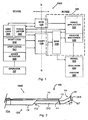
- Fig. 1 presents a block diagram showing the mutual relationship and the main elements of the occlusion auger 1000 when in operation, with a proximal ex vivo portion, and a distal in vivo portion, shown separated by a dashed line S-S.
- a guiding catheter wherethrough the in vivo portion of the occlusion auger 1000 is introduced into the patient, and the patient, are not shown in Fig. 1 .
- An operator OP handles the occlusion auger 1000 via an ex vivo auger actuator 500, which controls an in vivo auger tool 100 operating a distal portion of the wire 120 and of the shaft 130.
- the auger tool 100 has for example, a flexible and resilient element, such as a bow 110, fixedly coupled to the distal portion of the shaft 130, and removably engaging an in vivo force applicator 122 fixed to the in vivo distal extremity of the wire 120.
- the wire 120 is first navigated distally via blood vessels 300, inside vessel walls 310, until the force applicator 122 engages an occlusion 320, or a furrow 340 in an occlusion 320. Then, the shaft 130 and the force applicator 122 are coupled and operated to flex and arcuate the bow 110. Thereby, the force applicator 122 and the extrados of the arcuate flexed bow back 117 are embeded in occlusion tissue lining the furrow 340, in releasable anchoring disposed adjacent opposite vessel walls 310.
- flexing the bow 110 dilates the furrow 340 asymmetrically into one radial direction, providing forces to provoke and initiate a crack propagation mechanism in the occlusion 320, and to further open and distally deepen the furrow 340. Thereafter, forces on the bow 110 are released whereby the elastic energy accumulated therein while flexing is liberated to expand the bow 110, and to introduce the force applicator 122 by one step-length distally deeper into the furrow 340.
- the flexure to arcuate and the release to expand the bow 110 are respectively, a first and a second state of a sequence having two phases, controllably operated in successive repetition by the auger actuator 500 to cross the occlusion 320. If necessary, repetitive operation of a plurality of sequences is reiterated successively to traverse one or more occlusions.
- the auger tool 100 coils-up when flexing, and uncoils when expanding, to progresses distally in a worm-like type of crawling process.
- the auger actuator 500 has a shaft locking mechanism 540, or shaft lock 540, a step-length limiting mechanism 541, or stepper 541, and a force limiter 542, all coupled to the shaft 130. Furthermore, the auger actuator 500 has a wire locking mechanism 560, and a force limiter, other than the shaft force limiter, but also marked as 542 in Fig. 1 , which are coupled to the wire 120. It is noted that the force applicator 122 and the bow 110 return feedback control information to the force limiter 542.
- release mechanism 125 to decouple the force applicator 122 in vivo from the bow 120, as further described in detail hereinbelow.
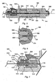
- Fig. 2 shows a side elevation view of the in vivo auger tool 100, as an exemplary embodiment of a portion of the occlusion auger 1000, according to Fig. 1 .
- the auger tool 100 includes a shaft 130, such as that of an available intravascular catheter system for the treatment of occluded blood vessels.
- the shaft 130 is distally terminated by one bow 110 that is flexible and resilient, and has a distal end terminated by a face 112 wherein a face bore 113 is opened.
- a guide wire 120, or wire 120 is disposed coaxially through the interior of the shaft 130 and through the face bore 113, which is configured to allow controlled bi-directional translation and rotation of the wire 120.
- the wire 120 has a flexible and resilient free distal extremity portion 121, terminated by a force applicator 122, shown as a bulb 122B, and accommodated to variably and reversibly extend distally away from the face 112.
- a force applicator 122 shown as a bulb 122B
- both the force applicator 122 and the bow 110 include a radio opaque material so that an operator OP viewing an imaging system, for example a Computer
- CT Tomography
- Radiograph may visualize the disposition of the force applicator 122 with respect to the face 112.
- the distal extremity portion 121 of the wire 120 As shown in Fig. 2 , the distal extremity portion 121 of the wire 120, extending distally away from the face 112, is bent to an angle a with respect to the shaft 130.
- the distal extremity 121 becomes a directrix that describes the mantle of a cone. Therefore, when the wire 120 is disposed in the interior of a vessel 300, and the operator OP desires to introduce the distal extremity portion 121 past a curve or into a branch of a vessel 300, the wire 120 is rotated until the distal extremity portion 121 points into the direction appropriate to proceed past the curve or into the branch.
- Figs. 2 and 3 also indicates details of the shaft 130, such as the proximal end 134, the in vivo distal end 135, the exterior 136, and the interior 137, which supports a wire 120 therein. Also shown are the ex vivo proximal extremity 125and the in vivo distal extremity portion 121, of the wire 120.
- Fig. 3 is a longitudinal cross-section of Fig. 2 , where the bulb 122B is shown retracted proximally and in abutment with the face 112, in contrast with the position depicted in Fig. 2 , where the bulb 122B is shown in distal extension away from the face 112.
- a relief 114 which locally decreases the cross-sectional area of the bow 110, defines a specific location about which the bow 110 will flex and bend when urged to arcuate.
- the shape of the relief 114 is irrelevant as long as the functional requirements are met, and may be implemented as a cutout formed by plane sections, or as a rounded-off curve of a selected shape.
- the shape of the relief 114 is thus not limited to any specific configuration and may be selected as desired.
- the portion of the bow 110 extending from the proximal extremity thereof to the relief 114 forms a bow root 115, and the portion of the bow 110 extending from the relief 114 to the face 112 forms a bow back 117.
- the bow root 115 and a proximal portion of the bow back 117 are disposed in a cutout 132 entered in the distal portion of the shaft 130, so that the bow 110 longitudinally extends in co-alignment with the shaft 130.
- the bow 110 is made for example, from a super-flexible and resilient material, such as nitinol, and is exemplarily, about 1.4 centimeters long.
- the force applicator 122 is disposed in longitudinal coextensive distal alignment with the face 112 and the bow 110, which is configured to taper from the bow root 115 distally away, forms a single protrusion extending radially outward relative to wire 120, as shown in Fig. 2 .
- the force applicator 122 is disposed in longitudinal coextensive distal alignment with the face 112 and the bow 110, which is configured to taper from the bow root 115 distally away, forms a single protrusion extending radially outward relative to wire 120, as shown in Fig. 2 .
- the bow 110 tapers distally away, thus having a larger cross-sectional area proximally than distally.
- the bow 110 is one possible implementation of a portion of the auger tool 100.
- the bow 110 is a flexible and resilient beam cantilevered to the shaft 130 with the face 112 as the beam free end.
- the bow back 117 is actually a flat spring for which the distal taper provides a lower spring rate or spring coefficient at the distal extremity, here the face 112, than at the proximal cantilevered extremity, here the relief 114.
- the importance of the bow 110 being a "softer" distally, and a "harder” proximally is detailed hereinbelow.
- the bow root 115 and at least a proximal portion of the relief 114 are belted by a surrounding shrink tube 116.
- the shrink tube 116 is shrunk to fixedly retain the bow 110 in co-alignment to the shaft 130, and to prevent any relative motion between the bow 110 and the shaft 130.
- the shrink tube 116 also grips the relief 114 to better anchor the bow 110 onto the shaft 130.
- the bow back 117 is not covered by the shrink tube 116, and is thus free to flex.
- the fixed retention of the bow root 115 to the shaft 130 is possibly achieved with any practical means available, and is not restricted to the use of a shrink tube 116, as further described hereinbelow.
- the shrink tube 116 is selected from materials that can be induced to form a strong attachment to the bow 110, for example, materials including Nylon 11TM or Nylon 6TM. It is remarked that the shaft 130 may have a diameter of 0.55 mm for example.
- Fig. 3 illustrates a coiled spiraling wire jacket 124 encasing the distal extremity portion 121 of the wire 120.
- the wire jacket 124 is about 20 cm long and remains conformal to the wire 120 that tapers distally along that same length, from, say a diameter of 0.05 mm, down to 0.01 mm.
- the face bore 113 has a diameter of 0.3 mm and the bulb 112B is 0.35 mm in diameter.
- Fig. 3 also depicts that the distal portion of the wire 120 includes a core wire 126 encased in the spiraling wire jacket 124.
- the wire jacket 124 is 1 to 0.5 millimeters in diameter and the core wire 126 has a diameter ranging from 0.05 mm to 0.01 mm.
- auger tool 100 was described as having a bow 110, other implementations are possible, as long as the functional and atraumatic requirements are respected. This means that it is always necessary to assure controlled tension and flexure forces, to control radial outward extension in the arcuate state, as well as distal translation when in return to the expanded state.
- Fig. 4 presents the ex vivo auger actuator 500 for the operation of the in vivo auger tool 100
- Fig. 5 is a longitudinal cross-section of Fig. 4 .
- the auger actuator 500 includes a distal shaft control 501 supported concentrically in proximal co-aligned extension by a substantially cylindrical wire handle 550.
- a common axial conduit 510 pierces both the distal shaft control 501 and the wire handle 550.
- a distal portion 503 of the conduit 510 passing throughout the distal shaft control 501 is configured to accommodate free passage therethrough of the shaft 130, whereas a proximal portion 553 of conduit 510 passing throughout the wire handle 550 is configured to accommodate free passage therethrough of the wire 120.
- the shaft 130 which is disposed in the wider portion 503, cannot penetrate into the narrower proximal portion 553 of the conduit 510 passing through the wire handle 550.
- the shaft control 501 is of unitary construction and includes a shaft-nose 530, a collar 532, and a shaft body 534, all of generally cylindrical shape and disposed in concentric coextensive alignment.
- the shaft-nose 530 is oriented in the distal direction, proximally followed first by the collar 532 and second, by the shaft body 534.
- the collar 532 protrudes radially outward and away from the external surface of the shaft-nose 530, the shaft body 534, and the wire handle 550.
- a wire locking mechanism 560, or wire lock 560 is proximally and coaxially appended to the wire handle 550.
- Fig. 5 further depicts a step limiter 541, or stepper 541, for setting a step length, for example by help of a setscrew 543 coupled to the wire handle 550, where the setscrew 543 is received in a relief 545 cut in the shaft body 534, operating as described hereinbelow.
- a step limiter 541, or stepper 541 for setting a step length, for example by help of a setscrew 543 coupled to the wire handle 550, where the setscrew 543 is received in a relief 545 cut in the shaft body 534, operating as described hereinbelow.
- the shaft body 534 is configured as a male cylinder coaxially received in the interior of an axial female bore entered into the wire handle 550, and is configured to permit mutual relative displacement in bi-directional translation and in bi-directional rotation, between both the shaft control 501 and the wire handle 550.
- the collar 532 is displaceable in bi-directional rotation and in translation distally outward and away therefrom, and proximally back therein.
- the auger actuator assembly 500 is designed to permit precise control of the bi-directional displacement in translation and in rotation of both the wire 120 and of the shaft 130, as described in detail hereinbelow.
- Fig. 6 is an enlarged detail of the wire-locking mechanism 560, having a configuration well known to the art, and permitting to reversibly lock the guide wire 120 relative to the wire handle 550, when desired.
- a threaded extension 562 carrying an external male screwthread is disposed concentrically and in proximal coextension to the proximal extremity of the wire handle 550 for matching engagement with a female screwthread disposed on the interior of a cap nut 564.
- the proximal portion 553 of the common axial conduit 510 coaxially pierces both the threaded extension 562 and the cap nut 564.
- a wire glans 566 having an axial bore for the passage of the wire 120 therethrough, has a wire stem 568 and wire locking jaws 570.
- the wire stem 568 and the wire locking jaws 570 are received in an appropriate widening entered in the proximal extremity 553 of the axial conduit 510.
- the wire locking jaws 570 of the glans 566 resiliently separate into a plurality of flexible and resilient jaws configured to operate as a cone-locking mechanism. Further details for this well-known cone-locking mechanism are superfluous.
- the cap nut 564 when the female cap nut 564 is threadingly engaged on the male screw-threaded tail 562, the cap nut 564 applies compression forces on the wire locking jaws 570 that deflect to firmly lock onto the wire 120 and prevent displacement thereof relative to the wire handle 550. It is also clear that when the female cap nut 564 is threadingly disengaged from the male threaded tail 562, the wire locking jaws 570 resiliently release their grip on the wire 120, which then becomes able to freely translate and rotate relative to the wire handle 550.
- the wire locking mechanism 560 When the wire locking mechanism 560 is locked onto the wire 120, and the wire handle 550 is rotated clockwise and anticlockwise, then the wire 120 will rotate in the same direction, respectively, clockwise and anticlockwise. Likewise, the wire 120 can now be translated longitudinally distally or proximally to, respectively, extend distally out, as shown in Fig.2 , or to retract proximally.
- the wire locking jaws 570 are made from a material including for example, metal, such as brass, or a polymeric plastic material known by the trade name AcculonTM.
- the wire locking mechanism 560 has a built-in force limiting mechanism.
- the force applied by the wire locking jaws 570 on the wire 120 define the load under which the wire will slip out of the wire locking jaws 570.
- Other force limiting mechanisms are also applicable. Indication of the retaining force threshold of the wire 120 may also be provided.
- Fig. 7 shows a longitudinal axial cross-section of a shaft locking mechanism 540 disposed in the distal portion of the shaft control 501 in which a plurality of shaft locking jaws 528 releasably lock onto the shaft 130, thereby preventing longitudinal and rotational displacement of the shaft 130 relative to the shaft control 501.
- the shaft nose 530 is accommodated with a concentric nose opening 535 for receiving therein a shaft stem 531 of a shaft glans 533 having a plurality of flexible and resilient shaft locking jaws 528.
- the shaft locking jaws 528 concentrically pierced by the distal portion 503 of the axial conduit 510, operate to releasably lock onto the shaft 130 by a cone-locking mechanism configuration well known to the art.
- the shaft glans 533 is fixedly coupled in axial co-aligned disposition to a slider 524 accommodated to freely translate axially and longitudinally, thus both distally and proximally, in the interior of a chamber 536.
- the chamber 536 is a hollowed out volume disposed in the interior of the shaft nose 530.
- a resilient element 522 such as one or more helical coil spring(s) 522, appropriately housed in a blind spring bore 538 opened in parallel to the conduit 510 into the shaft nose 530, are accommodated to receive the spring(s) 522.
- the resilient element 522 biases the slider 524 proximally away. Thereby, the slider 524 retracts the shaft glans 533 into the shaft nose 530, whereby the shaft locking jaws 528 lock onto the shaft 130, preventing translation and rotation thereof relative to the shaft control 5 01.
- the shaft locking mechanism 540 When the shaft locking mechanism 540 is locked onto the shaft 130, and the collar 532 is translated distally and proximately, or rotated, then the shaft 130 also, respectively, translates distally and proximately, or rotates, relative to the wire handle 550, shown in Fig. 5 .
- the slider 524 is translated distally, whereby the shaft locking jaws 528 are pushed distally out of the nose opening 535, and flex radially out and away. Thereby, the resilient shaft locking jaws 528 open to release grip and release the shaft 130 to freely translate and rotate.
- a plunger 520 retained in pivotal freedom of motion to the shaft control 501, is provided with a wedge 521 configured to engage a matching groove 523 accommodated for this purpose in the slider 524.
- the wedge 521 pivots to engage the groove 523.
- the slider 524 is driven distally against the resilient element 522, to release the lock of the resilient shaft locking jaws 528 on the shaft 130.
- the shaft-locking mechanism 540 When the shaft-locking mechanism 540 is released by depression of the plunger 520, the shaft 130 is free to translate and rotate. It is also understood that the purpose of translation and rotation of the guide wire 120 and of the shaft 130 is to allow an operator OP to precisely operate and position the auger tool 100 with respect to an occlusion 320 disposed in a vessel 300. Moreover, the plunger 520 operates as an emergency button, permitting to immediately disconnect the shaft and to relieve the vessel 300 from any force or moment applied thereon by the auger tool 100.
- the shaft-locking mechanism 540 has a built-in force limiting mechanism, permitting to select a threshold limit to prevent the exertion of excessive forces on the force applicator 122, and on the bow 110.
- the bias exerted by the resilient element 522 on the slider 524 is the force by which the shaft glans 533 is pulled proximally, and the more spring bias, the more forceful the proximal pull.
- the proximal pull of the slider 524 is applied to the shaft glans 533 to lock the shaft 130 with a force proportional to the bias applied by the resilient element 522.
- One shaft retaining force control mechanism consists of replacing an installed resilient element 522 by a harder or softer one, to obtain, respectively, higher or lower shaft retention locking forces.
- shaft-locking force control mechanisms are possible.
- One example, not shown in the Figs., is the preloading of a spring 522, say by operating a controllable screw for the releasable axial compression of the spring. The more the spring 522 is compressed, the better the shaft locking jaws 528 clamp the shaft 130, and the higher the lock retention forces on the shaft 130.
- a force of magnitude lower than a limit threshold will prevent breakage of the guide wire 120 and separation of the force applicator 122 therefrom.
- the radial force of the bow 110 against a vessel wall 310 may be kept below a threshold limit, to prevent damage to a vessel 300.
- the shaft locking jaws 528 are made from an elastomeric material including, for example, a polymeric plastic material known by the trade name TeflonTM. Given the relatively low coefficient of friction of the selected material, the shaft-locking mechanism 540 will give way above a determined force, to allow the shaft 130 to slip on the shaft locking jaws 528, and prevent the application of a higher than desired force on the wire 120, on the force applicator 122, and on the bow 110.
- Fig. 5 depicts a conceptual embodiment of the step-length limiter 541, also indicated in Fig. 1 .
- the setscrew 543 coupled to the wire handle 550, and extending radially inward to be received in the relief 545, operates as a stopper to limit the step-length.
- the shaft body 534 is translated distally, the translation will stop when the setscrew 543 abuts the proximal wall 547 of the relief 545.
- the step-length limiter 541 is possibly implemented in various versions, not described herein.
- the setscrew 543, or any other mechanical stopper such as a pin may be disposed in adjustable setting on the wire handle 550 relative to the proximal wall 547, to provide for an adjustable step-length.
- the setscrew 543, or any other mechanical stopper such as a pin
- the setscrew 543, or any other mechanical stopper may be disposed in adjustable setting on the wire handle 550 relative to the proximal wall 547, to provide for an adjustable step-length.
- piercing bores into the wire handle 550 at various distances from the proximal wall 547, to achieves various step lengths when the setscrew 543, or a pin, are entered into an appropriately selected bore.
- other implementations of the step-length limiter 541 are possible.
- the operator OP is thus presented with a multi functional auger control 500, having a shaft lock 540 for releasably locking the shaft 130 relative to the auger control 500 and for limiting force applied on the shaft 130, a stepper 541 for distally translating the shaft 130 in predetermined step length, a wire lock 560 for releasably locking the wire 120 relative to the auger control 500 and for limiting force applied on the wire.
- the auger control 500 is configured for operative handling and control of the wire 120 and of the shaft 130 both independently and in combination.
- the auger control 500 is thus disposed ex vivo in operative association with the auger tool 100, including an inherent force limiting mechanism configured for the adjustable selection and for the setting of a predetermined threshold limit of shaft forces and of wire forces applied to the auger tool 100, and a step limiter configured for the adjustable selection and for setting of a predetermined distal step length identically taken and repeated in each one sequence of operation. It is not the operator OP but the auger control that maintains identical predetermined forces limit and step length settings for each sequence in a series of successively repeated sequences.
- the wire 120 and the shaft 130 maybe translated through, and retrieved distally out of the auger control 500, but the wire may be retrieved thereout proximally .
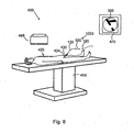
- Fig. 8 shows a typical operating room 400 used for a procedure with the occlusion auger 1000 that includes a surgical table 458, an imager 468 and an imaging display 470 that provides a real-time image of a treated vessel 300.
- a patient 420 is placed in the prone position on the table 458 and the shaft 130 is passed through a catheter 430 that enters the patient 420 through an incision 424 into a femoral artery 428, as illustrated in Fig. 9 .
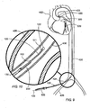
- Fig. 9 and Fig. 10 which is an enlarged detail of Fig. 9 , show a partial in vivo cross-section of the guiding catheter 430 entering through an incision 424 into the femoral artery 428, seen in cutaway.
- the auger actuator assembly 500 is manipulated so that the shaft 130 passes through the guiding catheter 430 toward a heart 482, where a catheter distal end 431 communicates with a coronary artery 490 having a vessel branch 300 that contains an occlusion 320.
- the auger tool 100 is operated with the force applicator 122 being extended distally away from the face 112, as seen in vivo in Fig. 10 .
- the distal wire extremity portion 121 terminated by the tool tip MT, hangs free in a flexible configuration, allowing the wire 120 to flex and curve through bends and branches encountered in blood vessels.
- the occlusion auger 1000 is supplied with a wire 120 that is about 185 cm long, and a shaft 130 having a length of some 140 cm.
- the force applicator 122 extends some 45 cm distally away from the face 112. That distance generally suits the operator. Extension pieces, not shown in the Figs. but used in common practice, may be attached to both the wire 120 and the shaft 130, if desired.
- the auger occlusion assembly 500 has to be manipulated as follows.
- the shaft locking mechanism 540 is locked while the wire locking mechanism 560 is released and the guide wire 120 is manually pushed distally relative to the wire handle 550, to extend say for some 40 to 100 mm.
- the wire locking mechanism 560 is locked, as is the shaft locking mechanism 540, so that translation of the auger tool 500 will simultaneously translate both the wire 120 and the shaft 130.
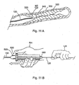
- a first step as shown in vivo in Fig. 11A , the operator navigates simultaneously both the shaft 130, not shown in Fig. 11A , and the wire 120, or only the wire 120, distally into the vessel 300, in manual translation toward and until the tool tip MT, here the force applicator 122, contacts the occlusion 320 as distally as possible, into the furrow 340.
- the shaft locking mechanism 540 is locked, and the wire locking mechanism 560 is unlocked.
- the guide wire 120 is kept in place by being firmly retained in one hand by the operator OP, say in the left hand LH, while the other hand pushes the auger actuator 500, thus also the shaft 130, in distal translation over the wire 120, as shown ex vivo in Fig. 11B .
- the shaft locking mechanism 540 is locked since the plunger 520 is not depressed.
- the distal translation terminates when the face 112 comes to rest in abutment with the force applicator 122, as shown in vivo in Fig. 12A .
- a visual feedback signal is provided ex vivo to the operator OP, to indicate that the bulb 122 is in mechanical contact with the face 112, by uncovering a mark, not shown in the Figs., disposed on the wire 120.
- a mark, sign, or indicia is appropriately disposed on a proximal portion of the wire 120, so that when the shaft is introduced distally to have the face 112 abut the bulb 122, the mark is uncovered ex vivo when contact is made, by appearing proximally out of the auger actuator assembly 500.
- the disposition and the relative location of the various components of the auger tool 100 are also presented to the operator on an X-ray device.
- the shaft locking mechanism 540 and the wire locking mechanism 560 are first locked.
- the auger actuator 500 is held by hand, as shown ex vivo in Fig. 12B , and the collar 532 is rotated in the desired direction, say by the thumb T, to rotate the shaft 130 together with the bow 110 and the face 112.
- the wire locking mechanism 560 and the shaft lock mechanism 540 locked, it is possible to rotate the collar 532 in either direction and to translate the shaft 130 distally, as shown ex vivo in Fig. 12B by, respectively, the arrows A and R.
- the auger tool 100 is now well positioned to threat an occlusion 320, either if penetration of the force applicator 122 into the furrow 340 was successful, as by Fig. 12C , or even when the force applicator 122 only abuts on the occlusion 320, as by Fig. 12A .
- a third step as seen in ex vivo in Fig. 13A , with the force applicator 122 abutting on the face 112, and with both the shaft and the wire locking mechanisms, respectively 540 and 560 being locked, the collar 532 is pushed distally away from the wire handle 550, which is firmly retained, in the palm of the hand H by the fingers F of an operator OP.
- the collar 532 is pushed with the thumb T to translate distally, in a direction indicated by the arrow A, causing the shaft 130 to translate distally relative to the wire 120, through an axial distance D, for example, of 0.5 centimeters.
- Transition from the expanded state following the arcuate state causes the tool tip MT to translate into the furrow 340 distally away from the arc depression, by one step length for each one sequence of operation.
- each next sequence of operation of the auger tool is accompanied by a next distal tip depression, and a next distal arc depression, and both the next distal tip and the next arc depression are disposed distally relative to, respectively, a previous tip and a previous arc depression.
- the resilient bow 110 is compelled to arcuate radially outward and away with respect to the guide wire 120, as shown in Fig. 13B .
- the face 112 is bent in oblique relative to the bow back 117, whereby the force applicator 122 first contacts the face 112 at a well predetermined point P, shown in Fig. 3 , where initial bending moments are applied.
- relief 114 defines the location where the bow 110 will begin to flex, and arcuate.
- the dimensions and the tapering of the flexible bow 110 are selected to ensure controlled predetermined curvature shapes for the radially outward bending of the bow 110 into a readily predictable mode of accurately defined deflection curvatures.
- the force applicator 122 embeds into one portion of the occlusion 320, creating a first tip depression 141, into which the force applicator 122 anchors.
- the extrados of the flexed bow back 117 of the arcuate bow 110 engages and embeds into a diametrically opposite lateral portion of the occlusion 320, creating a first arc depression 151.
- the vessel 300 is thereby dilated asymmetrically and radially outward, and the furrow 340 will crack open, in a type of crack propagation process, successively opening distally into newly opened furrow portions.
- the bending bow 110 applies forces to expand the occlusion material and open a passage along a true lumen, which is the last blood flow path that was available before occlusion occurred.
- the tool tip MT of the auger tool 110 and the extrados of the bow back 117 are embedded and releasably retained in, respectively, the tip depression 141 and the arc depression 151, or respectively, the tip anchor TA and the arc anchor AA that are disposed opposite to each other in spaced-apart relationship in the vessel 300.
- the vessel is dilated asymmetrically in radial outward direction for opening a furrow 340 in the occlusion 320.
- the force applicator 122 has to progress distally to engage into and penetrate the newly opened furrow portion 340.
- the collar 532 previously pushed through a distance D shown in Fig. 13A , is now gripped between the thumb T and the index IND.
- the other fingers F are opened to release the grip of the palm of the hand H on the wire handle 550, as shown ex vivo in Fig. 14B .
- the energy gathered in the arcuate bow 110 is released to push the face 112 distally, in the direction indicated by the arrow AR, until the wire handle 550 abuts on the collar 532.
- the release of the energy-loaded bow 110 from the arcuate state to the extended state drives the face 112, and also the force applicator 122 , distally into the furrow 340.
- the first arc depression 151 into which the arc anchor AA of the arcuate extrados of the bow back 117 is embedded, becomes a point of support wherefrom the face 112 uncoils distally. Therefore, with the arc anchor AA and the first arc depression as support, the shape of the curvature of the flexed bow 110 is different from that of any shape developed during the bending of the bow 110.
- the auger tool 100 is tensioned when the bow 110 is flexed to arcuate, by closing the distance separating the distal extremity of the shaft 130 from the face 112.
- the force applicator 122 is pushed distally further into the furrow 340.
- a single two-step sequence of operation of the auger tool 100 is not sufficient to traverse and occlusion 320, and the sequence of coiling and uncoiling in worm-like crawling process must be repeated.
- the collar 532 is pushed with the thumb T to translate distally, in the same manner as describe in relation to Figs. 12B and 13A .
- the bow 110 is arcuate, as shown in vivo in Fig. 15A , for the force applicator 122 to become engaged and anchored into a second tip depression 142, disposed distally away from the first tip depression 141.
- the bow back 117 becomes engaged and anchored into a second arc depression 152, disposed distally away from the first arc depression 151, in a lateral portion of the occlusion 320, diametrically opposite to the second tip depression 142.
- the collar 532 is gripped by the thumb T and the index IND, while the fingers F are released, in the same manner as described hereinabove in relation to Figs. 14A and 14B .
- the bow 110 expands and straightens out, distally past the second tip depression 142, and the bulb 122 is pushed to penetrate distally into the furrow 340, in the second step of the crawling process, as shown in vivo in Fig. 15B .
- the force applicator 122 engages a newly formed crack opened by asymmetric radial dilatation of the vessel 300.
- the crawling process of the auger tool 100 may be repeated as often as needed to further penetrate into the occlusion 320, and finally, to traverse and exit distally out of that occlusion.
- the auger tool 100 may be operated to traverse through a succession of occlusions disposed in the vessel 300, until the guide wire traverses and emerges distally away of the successive last occlusion.
- the bulb 122 progresses distally in successive steps of some 5 millimeters, prior to creating further tip and arc depressions.
- occlusion auger 1000 may traverse a partial or a complete occlusion 320 of virtually any length, including a hard Chronic Total Occlusion.
- the two-step sequence of flexing and expanding of the bow 110 is governed and controlled by the ex vivo auger actuator 500.
- the operator OP may select and set the step-length distance D out of a range of say 1 mm to 20 mm, and the selected distance D is maintained throughout the consecutive sequences of operation performed by the auger tool 100, until set anew by the operator OP.
- a radio-opaque dye 160 may be injected into the vessel 300.
- the interior of the vessel 300 thereby appears as a dark black area on the screen of an imaging system, clearly delimiting the borders of the vessel 300 and any occlusion 320. Thereby, tip depressions, lateral arc depressions, and cracks in a furrow 340 are well delimited.
- an image of the auger tool 100 taken prior to the injection of the dye 160 may be superimposed in contrast to the black dyed image, to define the disposition of the auger tool 100 relative to the occlusion 320.
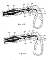
- Fig. 16A illustrates an example of the use of radio-opaque dye 160 prior to taking a bend 161 in an occlusion 320.
- the detected furrow 340 offers a narrow bent lumen extending distally away ahead of the bulb 122.
- the operator will respond to such a vessel configuration by trying to navigate the wire 120 accordingly, and insert the force applicator 122 as distally away as possible.
- the wire locking mechanism 560 is released while the shaft-locking mechanism 540 remains locked, and the wire 120 is manually translated distally, and rotated if necessary, until the wire 120 penetrates the furrow 340 as distally as possible, as shown in vivo in Fig. 16B .
- the accompanying manipulation of the auger control assembly 500 was described hereinabove, and is not repeated.
- the auger tool 100 has to be operated again in a sequence of two-phased crawling process steps.
- Fig. 17A depicts in vivo the arcuate bending of the bow 110 in radial direction, creating the asymmetric radial dilatation, and Fig.
- 17B presents the longitudinal straightening out and expanded bow 110, where the force applicator 122 is shown distally away through and past the occlusion 320.
- the auger tool 100 has thus embedded one more tip depression 145 and one more arc depression 155. Further successive crawling steps, in addition to the single step described hereinabove may be required to pierce past a more massive and longer occlusion 320.
- the occlusion auger 1000 may serve as a guide for additional surgical instruments used in simultaneous and/or following procedures.
- the wire 120 may be disposed distally away from the occlusion 320, as shown in Fig. 18 , whereafter the shaft 130 is retrieved proximally away, for the wire 120 to serve as a guide to an angioplasty catheter supporting, as desired, a balloon with or without a stent.
- the wire-locking mechanism 560 is unlocked while the shaft-locking mechanism 540 remains locked. Then, the guide wire 120 if pushed distally into the interior of the vessel 300, well distally past the occlusion 320, a shown in vivo in Fig. 18 .
- the auger tool 100 is retrieved ex vivo in proximal translation over the shaft 130.
- the proximal portion of the guide wire 120 is held stationary in one hand, while the other hand retrieves the auger actuator 500, and therewith also the shaft 130, by proximal translation of the face bore 113 over the shaft 130. This is achieved after the wire-locking mechanism 560 is unlocked and the shaft-locking mechanism 540 is locked.
- the operator may choose to unlock both the shaft-locking mechanism 540 and the wire-locking mechanism 560, and then remove the auger actuator 500 in proximal translation over the shaft 130 and the wire 120, after which, the-shaft 130 is translated proximally with respect to the wire 120, which remains in place.
- an angioplasty catheter 180 with a balloon 181, disposed around the shaft 130, as shown in Fig. 19A .
- the inflation of the balloon may be applied to symmetrically dilate the vessel 300 and to enhance the opening of a distal crack in the furrow 340.
- the angioplasty catheter 180 supports a stent, for use after operation.
- the bow 110 may be flexed to a selected degree, and be rotated about the wire 120 to cut into and disintegrate the thrombotic material of the occlusion.
- embolic particles may be released into the distal arterial structure. To prevent such an incident, it is desirable to provide for aspiration of these emboli.
- Aspiration is possibly achieved via the shaft 130, or by any other duct or lumen allowing fluid communication from an aspiration opening of the duct disposed in vivo at or proximate the distal extremity of the occlusion auger 1000, and leading to an exhaust exit opening of the duct, disposed ex vivo.
- Fig. 19B illustrates a suction duct 139 with a suction intake 139I opening adjacent the distal portion of the auger tool 100, appropriately configured and disposed to discharge any dislocated occlusion debris to an exhaust opening, not shown in Fig. 19B , but disposed ex vivo.
- the bow 110 when in the expanded state, is analog to a flat spring cantilevered to the shaft 130 at the relief 114 and having the face 112 as a free end.
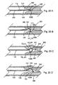
- the shaft 130 is distally translated toward the force applicator 122B, which is retained in place by the locked wire 120, disposed against the occlusion 320, as by Fig. 20B .
- the bow 110 is configured to taper and that the bow back 117 present a distally diminishing rigidity, thus a decreasing spring rate or spring coefficient, smallest adjacent the face 112. Therefore, when the bow is loaded to flex, the "softer" distal extremity bends first, followed by proximal portions of the bow back 117, coiling the bow back 117 to gradually roll in atraumatic deflection into occlusion tissue.
- Fig. 20B force is applied on the face 112, shown in Fig. 20A , and the bow starts to arcuate under the applied bending moment, in gentle and gradual atraumatic rolling motion, into occlusion tissue of the furrow 340.
- the bulb 122B forms a tip anchor TA that embeds into a tip depression 141 and the extrados of the bow 110 forms an arc anchor AA that embeds in an arc depression 151.
- the bow 110 has further coiled-up and rolled into the occlusion 320, anchoring the extrados deeper into the occlusion tissue, deepening the arc anchor AA and the arc depression 151, and asymmetrically dilating the vessel 300 radially outward.
- the bow flexing process ends when the face 112 practically abuts the distal extremity of the shaft 130.
- the arc anchor AA and the arc depression 151 extends distally relative to the tip anchor TA and the tip depression 141.
- the arc anchor and depression may have a span selected from the group of spans consisting of a span extending proximally and distally relative to the tip anchor and depression, a span extending proximally relative to the tip anchor and depression, and a span extending distally relative to the tip anchor and depression.
- the bow 110 is thus appropriately configured with a distally gradually diminishing spring rate coefficient for deflection under larger force at the bow root and under smaller force at the face, whereby controlled atraumatic bow deflection curvature is achieved. Therefore, the arc depression of the extrados is larger and more pronounced than the tip depression.
- the shaft 130 In return to the expanded state, and in reference to Fig. 20D , the shaft 130 is retained in place while the wire 120 is gradually released distally, relieving the bending moment applied to the bow 110.
- the extrados of the bow back 117, forming the arc anchor AA which remains embedded in the deepened arc depression 151, becomes a point of support wherefrom the face 112 uncoils distally.
- the bow 110 now presents an active distal portion spanning from the arc anchor AA or arc depression 151 to the tip anchor TA or tip depression 141, in contrast with the flexing state where the span ranged from the relief 114 to the tip anchor TA or tip depression 141. Therefore, the shape of the curvature of the expanding bow 110 is different from that of any shape developed during bending.
- the distal portion of the bow back 117 thus gradually uncoils in gentle atraumatic motion to push the force applicator 122 distally into the newly opened and deepened furrow 340. While the distal portion of the bow 110, extending between the first arc anchor AA or arc depression 151 and the tip anchor TA or tip depression 141 is released to straighten out, the proximal support of the bow 110 gradually regresses proximally toward the relief 114, which is reached upon return to the fully expanded state. This permits the force applicator 122 of the wire 120 to penetrate distally further into the furrow 340, as shown in vivo in Fig. 14C .
- controlled force threshold, step length limit and deflection curve of the bow 110 provide for control of the radial dilation and forces applied to the occlusion and to the vessel 300.
- the mechanism by which the auger tool operates is configured for flexing the bow back 117 into well controlled deflection curve shapes, and for embedding the tool tip MT first, and thereafter the extrados, to induce atraumatic rolling motion necessary for the radial outward dilation, and for the distal translation.
- the auger tool 100 translates substantially axially and distally into the vessel 300 in successive crawling motion imparted by each successive sequence of operation.
- the mechanism of operation provides for an auger tool 100 void of free-extending traumatic extremities:
- the bow back 117 has an extrados extending radially outward and away from the wire 120, but the bow root 115 is retained to the shaft 130, and the face112 is retained to the wire 120 by the face bore 113, not only for continuous control of the deflection of the bow 110, but whereby there is provided for the force applicator 122 to be the sole free-extending extremity of the auger tool 100.
- Figs. 21A to 21C are top elevations of the bow 110 and of the distal extremity of the shaft 130, showing alternative embodiments of the configuration and of the method used for retention of the bow root 115 to the shaft 130.
- the bow root 115 is best shaped to fit the functional demands required by the manufacturing techniques applied for the retention of the bow 110 to the shaft 130.
- a rectangular shape 170 for the bow root 115 is well suited, but an hourglass shape 171, shown in Fig. 21C , will suffice.
- 21B for retention of the bow root 115 to the shaft 130 may provide a better grip for fastening by help of a shrink tube 116.
- other configurations of the shape of the bow root 115 may be selected to better suit other fastening means for chemical or physical bonding, such as crimping, or any kind of soldering, blazing, welding, and diffusion fastening.
- fastening means for chemical or physical bonding such as crimping, or any kind of soldering, blazing, welding, and diffusion fastening.
- Figs. 22A and 22B illustrate an alternative embodiment of the bow 110, shown in bottom elevation.
- the alternative embodiment has a twisted face 112T presenting a pitch angle.
- the face 112T operates as a segment of a screwthread with a pitch angle to threadingly engage and progress through the occlusion 320.
- the perimeter 112P of the face may be configured as a cutting tool with a plurality of, but with at least one cutting-edge 112C, as shown in Fig. 22B .
- the twisted face 112T may chip through the occlusion 320. It is noted that the type of face, either the planar face 112 or the twisted face 112T, does no affect the controlled bending properties of the bow 110.
- the proximal retraction of the shaft 130 was achieved by sliding the face bore 113 of the bow 110, over the wire 120.
- This retraction method implies that the interior diameter of the face bore 113 must be large enough to permit the passage therethrough of the widest dimension of the wire 120.
- the force applicator 122 has a diameter wider than the interior diameter of the face bore 113.
- an alternative auger tool 200 is described hereinbelow, by which, when desired, the shaft 130 may become disengaged from the wire 120 and be retrieved proximally ex vivo, even though the interior diameter of the face bore 113 is smaller than the widest dimension of the shaft 130 and of the force applicator 122.
- Figs. 23A to 23C illustrate a distal portion of the auger tool, as embodiment 200, with a different type of force applicator 122 and face 112, and with reduced dimensions.
- Figs. 23A to 23C reference is made to the planar face 112, but the same applies to the twisted face 112T, with and without one or more cutting-edge(s) 112C.
- the force applicator 122 is configured as a limited length of male screwthread 122M disposed at the distal extremity of the wire 120, instead of the bulb 122B shown in Figs. 2 and 3 .
- the face 112, shown in Fig. 23B operates as a female screwthread 113F, or may be fitted therewith, in replacement of the cylindrical face bore 113, to receive the male screwthread 122M therein in matching and in extension therethrough.
- the male screwthread 122M is rotated and threadingly engaged until distally emerging thereout. Thereafter, once disposed distally out and away of the face 112, the male screwthread 122M will operate as a force applicator 122 when the wire 120 is pulled to urges onto the face 112. In distal translation of the shaft 130 relative to the static force applicator 122M, the male screwthread 122M will apply bending moment forces on the face 112 to arcuate the bow 110. It is noted that the face bore 113, or the female screwthread 113F, have a minimal inside diameter designated as w in Fig. 23B , whereas the same dimension w as shown on the male screwthread 122M in Fig. 23A , is smaller than the maximal external diameter of the force applicator 122.
- the auger tool 200 having a distal male screwthread 122M operates in the same manner as the auger tool 100 with the bulb 122B, to create a tip anchoring depression 141 when the bow is flexed to arcuate.
- the male screwthread 122M has reduced dimensions when compared to the bulb 112B.
- the male screwthread 122M has a maximal diameter ranging between 1.5 mm and 0.09 mm.
- the auger tool 200 when the operator desires to proximally retrieve the shaft 130 ex vivo, then the wire 120 is first rotated in screwthread unfastening rotation until the screwthread 122M is released proximally out of the face 112 or the face 112T, as shown when taking the Figs. 23A and 23B in mutual relation. Next, the shaft is pulled proximally causing the bow 110 to slightly flex radially outward, to enable sliding over the male screwthread 122M and over the length of the wire 120, and its supporting coils.
- FIG. 600 Another embodiment 600 of the auger tool is described, requiring limited angular rotation of the wire 120 for release from the face indicated as face 112 but also including face 112T.
- Fig. 24A shows a circular face bore 113, opened in the face 112, when the bow 110 is seen in front elevation.
- the substantially spherical bulb 122B also sown in front elevation, seen in Fig. 24B .
- Fig. 25A depicts a face 112 with an oval face bore 1130V
- Fig. 25B shows a matching ovaloid force applicator 1220V.
- the force applicator 122 is permanently attached to the distal extremity of the wire 120, and the force applicator 122 and the face bore 113 are configured for either one of both, permitting passage of the force applicator through the face bore, and preventing passage of the force applicator through the face bore.
- the force applicator 122 and the face bore 113 are configured for both, permitting passage of the force applicator 122 through the face bore 113, and preventing passage of the force applicator 122 through the face bore 113.
- the force applicator 122 is retained to the face 112 in proximally controlled attachment release.
- a minute portion 122T of the wire 120 may extend distally outward of the force applicator, shown as bulb 122B in Fig. 26 , but applicable to any force applicator 122.
- the tip portion 122T helps to better anchor the force applicator 122 into a tip depression 141 created in occlusion tissue.
- the auger tool may have other configurations, as long as atraumatic rolling motion is provided.
- the auger tool 100 which has at least one flexible portion, may have more such portions.
- the auger tool 100 may have one or more resilient portion(s).
- the auger control may be configurated for automatic repetition of the sequences of operation. Rather, the scope of the present invention is defined by the appended claims.
Landscapes
- Health & Medical Sciences (AREA)
- Surgery (AREA)
- Life Sciences & Earth Sciences (AREA)
- Medical Informatics (AREA)
- Animal Behavior & Ethology (AREA)
- Engineering & Computer Science (AREA)
- Biomedical Technology (AREA)
- Heart & Thoracic Surgery (AREA)
- Vascular Medicine (AREA)
- Molecular Biology (AREA)
- Nuclear Medicine, Radiotherapy & Molecular Imaging (AREA)
- General Health & Medical Sciences (AREA)
- Public Health (AREA)
- Veterinary Medicine (AREA)
- Surgical Instruments (AREA)
- Materials For Medical Uses (AREA)
- Centrifugal Separators (AREA)
- Prostheses (AREA)
- External Artificial Organs (AREA)
Abstract
Description
- The present invention relates to devices and methods for restoring blood flow in occluded blood vessels, and for traversing occlusions.
- Distal refers to both a direction of motion and a location, respectively, a movement in a direction away from an operator or a location further from the operator, for example a portion of an instrument located in vivo.
- Proximal refers to both a direction of motion and a location, respectively, a movement in a direction toward the operator or a location nearer to the operator, for example a portion of an instrument located ex vivo.
- Axial indicates the direction substantially in the longitudinal axis of a blood vessel.
- Lateral and radial refer to a direction substantially perpendicular to the longitudinal axis of a blood vessel.
- A furrow is considered hereinbelow as being a substantially
axial furrow 340 in thevessel 300. - Partial occlusion of any artery or vein of the body, herein a vessel, may slow blood flow to the extent that affected tissue may receive inadequate perfusion of life-giving oxygen, with sequelae of tissue ischemia, ischemic pain and tissue necrosis. In the heart, timely restoration of blood flow through occluded cardiac vessels can avert cardiovascular attack (CVA), tissue scarring, cardiac malfunction and/or death.
- A preferred treatment for restoring blood flow through a partially occluded blood vessel uses a percutaneously-delivered wire having a spiraling wire jacket, herein a guide wire, whose leading end is positioned distal to the occlusion. In angioplasty, for example, the guide wire is used to guide a balloon to the occlusion site where the balloon is expanded, thereby radially dilating the occlusion, and increasing blood flow through the vessel.
- In totally occluded blood vessels, including Chronic Total Occlusions (CTO's), the size of the occlusion and its hardness often make it impossible for a guide wire to navigate through and distally past the occlusion. Restoring blood flow through a totally occluded vessel often requires opening the chest and installing vessels that bypass the occlusion, a surgical procedure associated with high morbidity and risk of death.
- Many tools exist for the treatment of occluded blood vessels, all having their drawbacks.
- In
US Patent No. 6,599,304, Selmon et al. , teach a device with "...one or more hinged spreading or deflecting members that may be mechanically activated by an actuating member such as a pull wire or tube. A spreading or mechanical force may be thus applied to the blood vessel wall and occlusion so as to tear, fracture or otherwise disrupt, the occlusion adjoining the vessel wall. This disruption of the occlusion may create a channel or a passageway of sufficient size for the passage of a guidewire...". The deflecting members are divulged as being jaws operated by an actuation element: "An actuation wire or actuation member 54 may be provided within the assembly to move the jaw sections 42 from its first closed position to its second open position. In various embodiments, the jaw sections 42 may have a variety of geometries, including but not limited to, spade shaped, straight with a concave curve at the end, straight with convex curve at the end, triangular (needle nose), rectangular and combinations thereof." - In
US Patent No. 6,579,302, Duerig et al . teach a device with a spreader having a plurality of struts: "The spreader 15 may comprise a plurality of longitudinally or circumferentially arranged struts extending between the distal portion and the proximal portion of the spreader, such that advancing the spreader 15 over thecore wire 20 frees the struts and allows them to expand to their largest diameter, and advancing thecore wire 20 through the spreader 15 aligns the struts in a flat, closed position." - In
US Patent No. 5,954,742 , Osypka teach a device with an expander forming a cylindrical cage: "As can be seen, for example, inFigs. 6, 7 and8 , the expander or dilator 5 forms an elongated at least substantially cylindrical cage surrounded by straight elongated sections 5a' of the expanding elements 5a, and the sections 5a' are at least substantially parallel to each other and to the central longitudinal axis of the cage." - In
US Patent No. 5,741,270 , Hansen et al., teach: "A pair of resilient connecting members 202 are mounted onto the bracing member mounting pins 208 and to the retracting member mounting pins 210. The connecting members 202 are made of thin strips of resilient material which regain their original shape after being deformed. One end of each of the connecting members 202 is pivotally connected onto the bracing member mounting pins 208, whereas the other end of each of the connecting members 202 is pivotally connected to the retracting member mounting pins 210." - In
US Patent No. 4,648,402, Santos teaches a multilinkage mechanism: "Rear linkage 73 includes internal concave edge 773 and rear linkage 173 includes internal concave edge 873 which accommodate sphere 78 when it is in its most anterior position when mechanism 70 is in the closed configuration. In the open configuration of mechanism 70, there is also a net rearward displacement of front linkages 74 and 174, and of movable front section 76." - In
US Patent No. 4,848,342, Kaltenbach teaches a rotatable dilation catheter with a spring coil: "The catheter includes a flexible wire or elongated member 1 which is provided with a swelling or head with a spherically curved surface 2 at its distal end. A spring coil 3 is slipped onto the wire 1 and this spring coil has opened turns which are radially expandable at its distal end to form a pressure member 4. In the illustrated embodiment, the coil 3 is a double coarse coil of steel wires, which adjacent a distal end of the wire 1 has an increased spacing between the adjacent turns to form open turns. The diameter of the pressure member can be increased by axially compressing the open turns of the spring coil 3." - In
US Patent No. 6,800,085, Selmon et al. , teach a catheter with a housing: "The distal mounted housing may further include one or more hinged spreading or deflecting members that may be mechanically activated by an actuating member such as a pull wire or tube." Furthermore, there is an actuation device: "An actuation member indicated by dotted lines 26 may move or actuate the blunt end member from a first closed position, as illustrated inFIG. 1 , to a second open position, as illustrated inFIG. 2 ." - In
US Patent No. 6,638,247, Selmon et al. , teach a device with: "An actuation wire or actuation member 54 may be provided within the assembly to move the jaw sections 42 from its first closed position to its second open position. In various embodiments, the jaw sections 42 may have a variety of geometries, including but not limited to, spade shaped, straight with a concave curve at the end, straight with convex curve at the end, triangular (needle nose), rectangular and combinations thereof. The jaws 42 may be spaced apart or separated from one another even when closed as shown inFIG. 4 ." -
US Patent No. 5,662,606, by Cimino- et al. , recites a catheter which comprises a body member; and a manipulation handle attached to the proximal end of the body member. The catheter body is attached to the handle which also has a control device adapted for control movements in a first plane and in a second plane simultaneously. - A deflection control line is slidable in a direction parallel to the longitudinal axis of the body member and has its distal end attached to the distal portion of the catheter and its proximal end attached to the control device of the handle so that tension applied to the control line by movement of the control device in the first plane will cause the deflection of the distal portion of the catheter.
- A stiffening member is disposed within the body member of the catheter and is slidable in a direction parallel to the longitudinal axis of the body member, said stiffening member providing increased rigidity to the portion of the body member in which the stiffening member is located. Additionally, the stiffening member is connected at its proximal end to the control device of the handle such that movement of the control device in the second plane controls the position of the stiffening member in the body member. In a further aspect, a stiffening member in accordance with one embodiment includes a tapered distal end section with a ball formed on the distal tip, the tapered section terminating at the ball. The tapered section permits easier bending of this portion of the stiffening member so that as it is advanced into the body member, it may negotiate a bend in a catheter which is already in position. The ball protects the body member of the catheter from being pierced by the stiffening member as the stiffening member is advanced and contacts a bend in the body member.
- International Publication No.
WO 00/12009 PCT/US99/19123 by Burbank et al. -
US Patent No. 5,350,355 by M. Sklar recites "an automated surgical instrument that is adapted to mechanically drive a cannula toward and away from a stationary housing. The housing can be adapted to be held by a hand or can, otherwise, be adapted for mounting on a stationary or movable support. The user manipulates a switch or other control to power a linear motor within the housing that drives a cannula to place its distal end at a predetermined distance from the housing. As such, the cannula may be brought to a certain point within the body through an incision and subsequently driven to an appropriate area upon which an operation is to occur." Furthermore, "the automated surgical instrument comprises a housing; a substantially rigid tube having a lumen, a distal end projecting from an end of the housing and a proximal end positioned within the housing." -
US Patent No. 5,211,651 by Reger, et al . recites "a catheter atherotome which is manually operable and by which a surgeon can plane away atherosclerotic plaque from within an artery by entering the artery with a catheter at a single point proximal to the plaque deposit. The plaque is cut away piecemeal, by serial pullback strokes of a basket knife carried on the distal end of the catheter and which is collapsible to a small diameter conforming to the diameter of the catheter itself. The basket knife of the catheter atherotome includes several blades which are aligned generally parallel with one another and in a generally helical arrangement about an inner portion of the catheter which extends distally beyond the distal end of an outer sheath portion of the catheter when the basket knife is in a radially contracted, relaxed configuration. Respective ends of each blade are attached to the inner member and the outer sheath of the catheter so that when the distal end of the inner member is moved closer to the distal end of the outer sheath the blade members are forced to bow outward, expanding the basket knife radially. In a preferred embodiment of the invention, both the longitudinal position and the rotational position of the inner member of the catheter are adjustable relative to the outer sheath, and the several blades are flexible, so that both the pitch and the amount of radial bowing of the blades are controllable. Preferably, the angle of attack of the sharpened edge is such that it will engage atherosclerotic plaque but not normal arterial lining tissue." - None of the above mentioned disclosures teach an in vivo device having a bow, as a single asymmetric radially outward extensible flexible element with reduced radial dimensional configuration, and void of free radially extending extremities to prevent traumatic lesions to vessels, that dilates an occluded blood vessel and permits to traverse an occlusion in successively repetitively predetermined controlled identical steps. Additionally, controlled flexion and extension of the bow, in controlled force application and step-length, provide for a type self-propelled device that dilates an occluded blood vessel and permits to traverse an occlusion, without relying on the skills and dexterity of the operator.
US Patent No. 5,989,263 to Shmulewitz recites apparatus having a symmetric dilation mechanism wherein a plurality of longitudinal flexible members are flexed diametrically to expand radially outward and develop high compressive forces required to disrupt plaque. - An occlusion auger (100) is used for penetrating and traversing an occlusion (320) in a blood vessel (300) by performing a plurality of repeatable atraumatic single-sequence two-state consecutive actions including first radial dilatation in one direction to crack open a furrow (340) in the occlusion, followed second by distal penetration into the furrow, and vice versa.
- An occlusion auger (100) having an ex vivo auger control operates an in vivo auger tool. Initially, the auger tool, trailing a shaft (130) containing a guide wire (120) is navigated adjacent the occlusion or in a furrow of the occlusion. In parallel or in sequence, predetermined values are set at the auger control, namely dilatation threshold forces and distal penetration step-length.
- Next, the auger tool is operated under control of the predetermined values, to sequentially repeat identical radial dilation and distal penetration steps, without relying on the skills of the operator (OP). However, it is the task of the operator to conduct the auger tools axially into the vessel.
- An aspect of some embodiments of the invention relates to a device for augmenting a blood flow passage through a partially or fully occluded blood vessel, the device including an auger tool adapted for use in an in vivo blood vessel. A vessel occlusion auger, or occlusion auger, having an auger tool commanded by an ex vivo auger control, is defined as a device for use in an invasive surgical procedure to open a lumen through a partial or total occlusion disposed in a blood vessel.
- The auger tool is configured to provide atraumatic engagement of in vivo tissue, in rolling motion, under controlled force threshold and translation distance limits.
- It is an object of the present invention to provide an occlusion auger (1000) and a method for implementing the occlusion auger, for distally traversing an occlusion (320) in a vessel (300) having vessel walls (310). There is provided an auger tool (110) configured for atraumatic repeatable operation in a sequence including both deflection to an arcuate state extending radially outward, and release to an expanded and straightened state, and vice versa. The auger tool has an extrados when arcuate, and also a tool tip (MT). In the arcuate state, when the auger tool is disposed adjacent the occlusion, the tool tip and the extrados are embedded and releasably retained in, respectively, a tip depression (141) and an arc depression (151) disposed opposite to each other in spaced-apart relationship in the vessel, whereby the vessel is dilated asymmetrically in radial outward direction for opening a furrow (340) in the occlusion.
- Furthermore, in the expanded state, following the arcuate state, the tool tip translates into the furrow distally away from the arc depression, by one step length for each one sequence of operation. Each next sequence of operation of the auger tool is accompanied by a next distal tip depression, and a next distal arc depression, and both the next distal tip and the next arc depression are disposed distally relative to, respectively, a previous tip and a previous arc depression.
- Moreover, the auger tool is configured for flexing in controlled deflection curve shape. Also, by embedding the tool tip first and thereafter the extrados induces atraumatic rolling motion is provided for radial outward dilation, and for distal translation.
- It is another object of the present invention to provide an auger tool for operation in a specific number of successive sequences, accompanied by a same specific number of radial outward dilations and of distal translations. The auger tool translates substantially axially and distally into the vessel in successive crawling motion imparted by each successive sequence of operation.
- It is yet another object of the present invention to provide an occlusion auger having a shaft (130) with an ex vivo proximal end (134), an in vivo distal end (135), an exterior (136), and an interior (137) supporting therein a wire (120) having an ex vivo proximal extremity (125) and an in vivo distal extremity portion (121). The auger tool (100) has a flexible and resilient bow (110) disposed in distal coextensive longitudinal alignment with the distal end of the shaft, and the bow has a bow back (117) intermediate a bow root (115) fixedly attached to and supported by the distal end of the shaft, and a face (112, 112T, 1120V) extending distally away from the bow back, the face having a face bore (113, 113F, 113OV), which is configured for passage therethrough of the wire. In addition, a force applicator (122, 122B, 122M, 122OV) retained at the distal extremity of the wire, is configured for operative association with the face bore and with the shaft, to flex the bow to the arcuate state when the shaft is translated distally relative to the force applicator, for the extrados to dilate the vessel in asymmetric radial outward direction, and to release the bow to the expanded state when the wire is released, for the face to translate the force applicator distally away relative to the arc depression by one predetermined step length for each one sequence of operation.
- The force applicator has at least one flexible portion, and at least one resilient portion.
- It is still another object of the present invention to provide a force applicator that is disposed in longitudinal coextensive distal alignment with the face, and where the bow is tangential to and longitudinally aligned with the shaft, and is configured to taper from the bow root distally away, forming a single protrusion extending radially outward relative to the wire, whereby alignment of the force applicator with the bow, tapering of the bow, and the single radial protrusion enhance reduced dimensions.
- It is yet still another object of the present invention to provide a force applicator that is permanently attached to the distal extremity of the wire, and where the force applicator and the face bore are configured for either one of both, permitting passage of the force applicator through the face bore, and preventing passage of the force applicator through the face bore. In addition, the force applicator and the face bore may be configured for both, permitting passage of the force applicator through the face bore, and preventing passage of the force applicator through the face bore. Likewise, the force applicator may be retained to the face in proximally controlled attachment release.
- It is a further object of the present invention to provide a bow that is configured with a distally gradually diminishing spring rate coefficient for deflection under larger force at the bow root and under smaller force at the face, whereby controlled atraumatic bow deflection curvature is achieved. Moreover, the bow is configured with a distally gradually diminishing spring rate coefficient for deflection under larger force at the bow root and under less force at the face, and the arc depression of the extrados is larger than the tip depression.
- It is yet a further object of the present invention to provide occlusion auger having an auger control (500) that is disposed ex vivo in operative association with the auger tool, including a force limiter configured for adjustable selection and setting of a predetermined threshold limit of forces applied to the auger tool, and a step limiter configured for adjustable selection and setting of a predetermined distal step length taken in each one sequence of operation.
- It is yet still a further object of the present invention to provide an auger control that maintains identical predetermined forces limit and step length settings for each sequence in a series of successively repeated sequences. Furthermore, the auger tool includes
a shaft lock for releasably locking the shaft relative to the auger control and for limiting force applied on the shaft, and a stepper for distally translating the shaft in predetermined step length,
a wire lock for releasably locking the wire relative to the auger control and for limiting force applied on the wire, and
the auger control is configured for operative handling and control of the wire and of the shaft both independently and in combination. - It is an additional object of the present invention to provide an occlusion auger that when in the arcuate state has a bow back with an extrados extending radially outward and away from the wire, and the bow root is retained to the shaft, and the face is retained to the wire by the face bore, for continuous control of the deflection of the bow, whereby the force applicator is the sole free-extending extremity of the auger tool.
- It is yet an additional object of the present invention to provide an occlusion tool that has at least one cutting edge (112C) disposed on a perimeter (112P) of the face to extend radially outward and away from the face bore, and where the at least one cutting edge is configured for radially cutting into occlusion tissue, in vivo
- It is yet still an additional object of the present invention to provide an occlusion tool where:
- a. the force applicator is navigated to engage an axial furrow in an occlusion,
- b. the face is abutted on the force applicator,
- c. the auger tool is operated to the arcuate state, whereby kinetic energy is accumulated and the bow asymmetrically dilates the vessel into one radial outward direction,
- d. the auger tool is released to the expanded state, and the released kinetic energy extends the bow to translate the force applicator distally into the furrow, and
- e. the sequence of steps c. and d. are successively repeatable until the occlusion is traversed and augmented blood flow is restored.
- It is one more additional object of the present invention to provide an occlusion tool where when in the arcuate state, the force applicator releasably embeds in a tip depression, the extrados embeds in an arc depression to dilate the furrow, and initiate a crack propagation mechanism to open and distally deepen the furrow, and when in the expanded state, the force applicator is received by one step length distally deeper in the deepened furrow.
- It is yet still another additional object of the present invention to provide an occlusion tool where when in the arcuate state, the force applicator releasably embeds in a tip depression, the extrados embeds in an arc depression to dilate the furrow, and initiate a crack propagation mechanism to open and distally deepen the furrow, and when in the expanded state, the force applicator is received by one step length distally deeper in the deepened furrow
- It is still a further object of the present invention to provide an occlusion auger wherein when the force applicator extends distally past an occlusion, either one of both operations is performed:
- the wire is navigated to engage a next occlusion and a next occlusion traversing sequence is performed, and
- the shaft is proximally retrieved ex vivo while the wire remains disposed in place for use in a next treatment intervention
- It is moreover a further object of the present invention to provide an occlusion auger wherein when the force applicator extends distally past a traversed occlusion, the shaft is retrievable ex vivo, by either one of both:
- retrieving the face bore proximally away relative to the force applicator and sliding the face bore over the wire, and
- disengaging the face distally away from the force applicator, and retrieving the shaft proximally.
- It is furthermore an object of the present invention to provide an occlusion auger wherein the auger tool is configured to accommodate locking, translation, and rotation of the shaft and of the wire in either one of both mutually independent operation, and in mutually associative operation.
- It is furthermore still an object of the present invention to provide an occlusion auger wherein the arcuate state is achieved, by distal translation of the shaft relative to and over the wire until the face abuts the force applicator, and the expanded state is achieved by distal translation of the wire relative to the shaft. The distal translation has a step length that ranges from 1 mm to 50 mm.
- It is yet still a further object of the present invention to provide an occlusion auger wherein the tip depression is disposed opposite the arc depression, and the arc depression has a span selected from the group of spans consisting of a span extending proximally and distally relative to the tip depression, a span extending proximally relative to the tip depression, and a span extending distally relative to the tip depression.
- Non-limiting embodiments of the invention will be described with reference to the following description of exemplary embodiments, in conjunction with the figures. The figures are generally not shown to scale and any measurements are only meant to be exemplary and not necessarily limiting. In the figures, identical structures, elements or parts which appear in more than one figure are preferably labeled with a same or similar number in all the figures in which they appear, in which:
-
Fig. 1 is a schematic block diagram of the occlusion auger, -
Fig. 2 shows a side elevation of the distal in vivo portion of the vessel occlusion auger, according toFig. 1 , -
Fig. 3 is a longitudinal cross-section of the side elevation shown inFig. 2 , -
Fig. 4 shows an ex vivo auger actuator for the operation of the vessel occlusion auger, -
Fig. 5 is a longitudinal cross-section of the auger actuator shown inFig. 4 , -
Fig. 6 is an enlarged detail of the wire-locking mechanism of the auger actuator shown inFig. 5 , -
Fig. 7 is an enlarged detail of the shaft locking mechanism of the auger actuator shownFig. 5 , -
Fig. 8 shows a typical operating room used for a procedure with the occlusion auger according toFig. 1 , -
Figs. 9 and 10 show partial in vivo cross-sections of a procedure with the occlusion auger according toFig. 1 , -
Figs. 11A, 11B ,12A to 12C ,13A, 13B , and14A to 14C show details of the navigation and the use of the occlusion auger ofFig. 1 , -
Figs. 15A, 15B ,16A, 16B ,17A, 17B , and18 , show details of the operation of the occlusion auger ofFig. 1 , -
Figs. 19A and 19B shows enhancements of the occlusion auger ofFig. 1 , -
Figs. 20A to 20D illustrate the mechanism of bending and expansion of the occlusion auger ofFig. 1 , -
Figs. 21A to 21C depict various bow root configurations, -
Figs. 22A and 22B present optional embodiments of the face of the bow, -
Figs. 23A to 23C depict a further embodiment of the auger tool, and -
Figs. 24A, 24B, 25A to 25C, and 26 show details of various optional embodiments for the force applicator and the face of the bow, -
Fig. 1 presents a block diagram showing the mutual relationship and the main elements of theocclusion auger 1000 when in operation, with a proximal ex vivo portion, and a distal in vivo portion, shown separated by a dashed line S-S. Ashaft 130 and aguide wire 120, orwire 120, both have a proximal ex vivo portion and a distal in vivo portion. A guiding catheter wherethrough the in vivo portion of theocclusion auger 1000 is introduced into the patient, and the patient, are not shown inFig. 1 . - An operator OP handles the
occlusion auger 1000 via an exvivo auger actuator 500, which controls an invivo auger tool 100 operating a distal portion of thewire 120 and of theshaft 130. In thepreferred embodiment 1000, theauger tool 100 has for example, a flexible and resilient element, such as abow 110, fixedly coupled to the distal portion of theshaft 130, and removably engaging an invivo force applicator 122 fixed to the in vivo distal extremity of thewire 120. - In operation, the
wire 120 is first navigated distally viablood vessels 300, inside vessel walls 310, until theforce applicator 122 engages anocclusion 320, or afurrow 340 in anocclusion 320. Then, theshaft 130 and theforce applicator 122 are coupled and operated to flex and arcuate thebow 110. Thereby, theforce applicator 122 and the extrados of the arcuate flexed bow back 117 are embeded in occlusion tissue lining thefurrow 340, in releasable anchoring disposed adjacent opposite vessel walls 310. - In operation, flexing the
bow 110 dilates thefurrow 340 asymmetrically into one radial direction, providing forces to provoke and initiate a crack propagation mechanism in theocclusion 320, and to further open and distally deepen thefurrow 340. Thereafter, forces on thebow 110 are released whereby the elastic energy accumulated therein while flexing is liberated to expand thebow 110, and to introduce theforce applicator 122 by one step-length distally deeper into thefurrow 340. - The flexure to arcuate and the release to expand the
bow 110 are respectively, a first and a second state of a sequence having two phases, controllably operated in successive repetition by theauger actuator 500 to cross theocclusion 320. If necessary, repetitive operation of a plurality of sequences is reiterated successively to traverse one or more occlusions. Figuratively, theauger tool 100 coils-up when flexing, and uncoils when expanding, to progresses distally in a worm-like type of crawling process. - The
auger actuator 500 has ashaft locking mechanism 540, orshaft lock 540, a step-length limiting mechanism 541, orstepper 541, and aforce limiter 542, all coupled to theshaft 130. Furthermore, theauger actuator 500 has awire locking mechanism 560, and a force limiter, other than the shaft force limiter, but also marked as 542 inFig. 1 , which are coupled to thewire 120. It is noted that theforce applicator 122 and thebow 110 return feedback control information to theforce limiter 542. - There is also an
optional release mechanism 125 to decouple theforce applicator 122 in vivo from thebow 120, as further described in detail hereinbelow. -
Fig. 2 shows a side elevation view of the invivo auger tool 100, as an exemplary embodiment of a portion of theocclusion auger 1000, according toFig. 1 . Theauger tool 100 includes ashaft 130, such as that of an available intravascular catheter system for the treatment of occluded blood vessels. Theshaft 130 is distally terminated by onebow 110 that is flexible and resilient, and has a distal end terminated by aface 112 wherein aface bore 113 is opened. Aguide wire 120, orwire 120, is disposed coaxially through the interior of theshaft 130 and through the face bore 113, which is configured to allow controlled bi-directional translation and rotation of thewire 120. Thewire 120 has a flexible and resilient freedistal extremity portion 121, terminated by aforce applicator 122, shown as abulb 122B, and accommodated to variably and reversibly extend distally away from theface 112. In an exemplary embodiment, both theforce applicator 122 and thebow 110 include a radio opaque material so that an operator OP viewing an imaging system, for example a Computer - Tomography (CT) or a Radiograph, may visualize the disposition of the
force applicator 122 with respect to theface 112. - As shown in
Fig. 2 , thedistal extremity portion 121 of thewire 120, extending distally away from theface 112, is bent to an angle a with respect to theshaft 130. When thewire 120 is rotated inside theshaft 130, then thedistal extremity 121 becomes a directrix that describes the mantle of a cone. Therefore, when thewire 120 is disposed in the interior of avessel 300, and the operator OP desires to introduce thedistal extremity portion 121 past a curve or into a branch of avessel 300, thewire 120 is rotated until thedistal extremity portion 121 points into the direction appropriate to proceed past the curve or into the branch. -
Figs. 2 and3 also indicates details of theshaft 130, such as theproximal end 134, the in vivodistal end 135, theexterior 136, and the interior 137, which supports awire 120 therein. Also shown are the ex vivo proximal extremity 125and the in vivodistal extremity portion 121, of thewire 120. -
Fig. 3 is a longitudinal cross-section ofFig. 2 , where thebulb 122B is shown retracted proximally and in abutment with theface 112, in contrast with the position depicted inFig. 2 , where thebulb 122B is shown in distal extension away from theface 112. - A
relief 114, which locally decreases the cross-sectional area of thebow 110, defines a specific location about which thebow 110 will flex and bend when urged to arcuate. The shape of therelief 114 is irrelevant as long as the functional requirements are met, and may be implemented as a cutout formed by plane sections, or as a rounded-off curve of a selected shape. The shape of therelief 114 is thus not limited to any specific configuration and may be selected as desired. - The portion of the
bow 110 extending from the proximal extremity thereof to therelief 114 forms abow root 115, and the portion of thebow 110 extending from therelief 114 to theface 112 forms a bow back 117. Thebow root 115 and a proximal portion of the bow back 117 are disposed in acutout 132 entered in the distal portion of theshaft 130, so that thebow 110 longitudinally extends in co-alignment with theshaft 130. Thebow 110 is made for example, from a super-flexible and resilient material, such as nitinol, and is exemplarily, about 1.4 centimeters long. - To reduce dimensions, the
force applicator 122 is disposed in longitudinal coextensive distal alignment with theface 112 and thebow 110, which is configured to taper from thebow root 115 distally away, forms a single protrusion extending radially outward relative towire 120, as shown inFig. 2 . Thereby, due to the alignment of theforce applicator 122 with thebow 110, the tapering of thebow 110, and the single radial protrusion, reduced dimensions are enhanced. - Although not shown in the Figs., the
bow 110 tapers distally away, thus having a larger cross-sectional area proximally than distally. Actually thebow 110 is one possible implementation of a portion of theauger tool 100. Thebow 110 is a flexible and resilient beam cantilevered to theshaft 130 with theface 112 as the beam free end. The bow back 117 is actually a flat spring for which the distal taper provides a lower spring rate or spring coefficient at the distal extremity, here theface 112, than at the proximal cantilevered extremity, here therelief 114. The importance of thebow 110 being a "softer" distally, and a "harder" proximally is detailed hereinbelow. - In an exemplary embodiment, the
bow root 115 and at least a proximal portion of therelief 114, are belted by a surroundingshrink tube 116. Theshrink tube 116 is shrunk to fixedly retain thebow 110 in co-alignment to theshaft 130, and to prevent any relative motion between thebow 110 and theshaft 130. Theshrink tube 116 also grips therelief 114 to better anchor thebow 110 onto theshaft 130. The bow back 117 is not covered by theshrink tube 116, and is thus free to flex. - The fixed retention of the
bow root 115 to theshaft 130 is possibly achieved with any practical means available, and is not restricted to the use of ashrink tube 116, as further described hereinbelow. If desired, theshrink tube 116 is selected from materials that can be induced to form a strong attachment to thebow 110, for example, materials including Nylon 11™ or Nylon 6™. It is remarked that theshaft 130 may have a diameter of 0.55 mm for example. -
Fig. 3 illustrates a coiledspiraling wire jacket 124 encasing thedistal extremity portion 121 of thewire 120. Thewire jacket 124 is about 20 cm long and remains conformal to thewire 120 that tapers distally along that same length, from, say a diameter of 0.05 mm, down to 0.01 mm. In an exemplary embodiment, the face bore 113 has a diameter of 0.3 mm and the bulb 112B is 0.35 mm in diameter. -
Fig. 3 also depicts that the distal portion of thewire 120 includes acore wire 126 encased in thespiraling wire jacket 124. In an exemplary embodiment, thewire jacket 124 is 1 to 0.5 millimeters in diameter and thecore wire 126 has a diameter ranging from 0.05 mm to 0.01 mm. For the sake of clarity, reference is made hereinbelow simply to "wire 120". - Although the
auger tool 100 was described as having abow 110, other implementations are possible, as long as the functional and atraumatic requirements are respected. This means that it is always necessary to assure controlled tension and flexure forces, to control radial outward extension in the arcuate state, as well as distal translation when in return to the expanded state. -
Fig. 4 presents the exvivo auger actuator 500 for the operation of the invivo auger tool 100, andFig. 5 is a longitudinal cross-section ofFig. 4 . - Referring to
Figs. 4 and5 , theauger actuator 500 includes adistal shaft control 501 supported concentrically in proximal co-aligned extension by a substantiallycylindrical wire handle 550. A commonaxial conduit 510 pierces both thedistal shaft control 501 and thewire handle 550. Adistal portion 503 of theconduit 510 passing throughout thedistal shaft control 501 is configured to accommodate free passage therethrough of theshaft 130, whereas aproximal portion 553 ofconduit 510 passing throughout thewire handle 550 is configured to accommodate free passage therethrough of thewire 120. Theshaft 130, which is disposed in thewider portion 503, cannot penetrate into the narrowerproximal portion 553 of theconduit 510 passing through thewire handle 550. - The
shaft control 501 is of unitary construction and includes a shaft-nose 530, acollar 532, and ashaft body 534, all of generally cylindrical shape and disposed in concentric coextensive alignment. The shaft-nose 530 is oriented in the distal direction, proximally followed first by thecollar 532 and second, by theshaft body 534. Thecollar 532 protrudes radially outward and away from the external surface of the shaft-nose 530, theshaft body 534, and thewire handle 550. Awire locking mechanism 560, orwire lock 560, is proximally and coaxially appended to thewire handle 550. -
Fig. 5 further depicts astep limiter 541, orstepper 541, for setting a step length, for example by help of asetscrew 543 coupled to thewire handle 550, where thesetscrew 543 is received in arelief 545 cut in theshaft body 534, operating as described hereinbelow. - The
shaft body 534 is configured as a male cylinder coaxially received in the interior of an axial female bore entered into thewire handle 550, and is configured to permit mutual relative displacement in bi-directional translation and in bi-directional rotation, between both theshaft control 501 and thewire handle 550. Relative to thewire handle 550, thecollar 532 is displaceable in bi-directional rotation and in translation distally outward and away therefrom, and proximally back therein. Theauger actuator assembly 500 is designed to permit precise control of the bi-directional displacement in translation and in rotation of both thewire 120 and of theshaft 130, as described in detail hereinbelow. -
Fig. 6 is an enlarged detail of the wire-lockingmechanism 560, having a configuration well known to the art, and permitting to reversibly lock theguide wire 120 relative to thewire handle 550, when desired. A threadedextension 562 carrying an external male screwthread is disposed concentrically and in proximal coextension to the proximal extremity of the wire handle 550 for matching engagement with a female screwthread disposed on the interior of acap nut 564. Theproximal portion 553 of the commonaxial conduit 510 coaxially pierces both the threadedextension 562 and thecap nut 564. - A
wire glans 566, having an axial bore for the passage of thewire 120 therethrough, has awire stem 568 andwire locking jaws 570. Thewire stem 568 and thewire locking jaws 570 are received in an appropriate widening entered in theproximal extremity 553 of theaxial conduit 510. Thewire locking jaws 570 of theglans 566 resiliently separate into a plurality of flexible and resilient jaws configured to operate as a cone-locking mechanism. Further details for this well-known cone-locking mechanism are superfluous. - It is understood that when the
female cap nut 564 is threadingly engaged on the male screw-threadedtail 562, thecap nut 564 applies compression forces on thewire locking jaws 570 that deflect to firmly lock onto thewire 120 and prevent displacement thereof relative to thewire handle 550. It is also clear that when thefemale cap nut 564 is threadingly disengaged from the male threadedtail 562, thewire locking jaws 570 resiliently release their grip on thewire 120, which then becomes able to freely translate and rotate relative to thewire handle 550. - When the
wire locking mechanism 560 is locked onto thewire 120, and thewire handle 550 is rotated clockwise and anticlockwise, then thewire 120 will rotate in the same direction, respectively, clockwise and anticlockwise. Likewise, thewire 120 can now be translated longitudinally distally or proximally to, respectively, extend distally out, as shown inFig.2 , or to retract proximally. - In an exemplary embodiment, the
wire locking jaws 570 are made from a material including for example, metal, such as brass, or a polymeric plastic material known by the trade name Acculon™. - The
wire locking mechanism 560 has a built-in force limiting mechanism. The force applied by thewire locking jaws 570 on thewire 120 define the load under which the wire will slip out of thewire locking jaws 570. Thus the more and the harder thecap nut 564 is screw threaded on the male threadedtail 562, the higher the retention force on thewire 120, and vice versa. Other force limiting mechanisms are also applicable. Indication of the retaining force threshold of thewire 120 may also be provided. - As described hereinbelow, translation, rotation, and standstill of the
wire 120 and of theshaft 130 are mutually independent, but may be operated in cooperative association. -
Fig. 7 shows a longitudinal axial cross-section of ashaft locking mechanism 540 disposed in the distal portion of theshaft control 501 in which a plurality ofshaft locking jaws 528 releasably lock onto theshaft 130, thereby preventing longitudinal and rotational displacement of theshaft 130 relative to theshaft control 501. - In an exemplary embodiment, the
shaft nose 530 is accommodated with aconcentric nose opening 535 for receiving therein ashaft stem 531 of ashaft glans 533 having a plurality of flexible and resilientshaft locking jaws 528. Theshaft locking jaws 528, concentrically pierced by thedistal portion 503 of theaxial conduit 510, operate to releasably lock onto theshaft 130 by a cone-locking mechanism configuration well known to the art. - The shaft glans 533 is fixedly coupled in axial co-aligned disposition to a
slider 524 accommodated to freely translate axially and longitudinally, thus both distally and proximally, in the interior of achamber 536. Thechamber 536 is a hollowed out volume disposed in the interior of theshaft nose 530. Aresilient element 522, such as one or more helical coil spring(s) 522, appropriately housed in a blind spring bore 538 opened in parallel to theconduit 510 into theshaft nose 530, are accommodated to receive the spring(s) 522. Theresilient element 522 biases theslider 524 proximally away. Thereby, theslider 524 retracts theshaft glans 533 into theshaft nose 530, whereby theshaft locking jaws 528 lock onto theshaft 130, preventing translation and rotation thereof relative to the shaft control 5 01. - When the
shaft locking mechanism 540 is locked onto theshaft 130, and thecollar 532 is translated distally and proximately, or rotated, then theshaft 130 also, respectively, translates distally and proximately, or rotates, relative to thewire handle 550, shown inFig. 5 . - To release the locked
shaft 130, theslider 524 is translated distally, whereby theshaft locking jaws 528 are pushed distally out of thenose opening 535, and flex radially out and away. Thereby, the resilientshaft locking jaws 528 open to release grip and release theshaft 130 to freely translate and rotate. To this end, aplunger 520, retained in pivotal freedom of motion to theshaft control 501, is provided with awedge 521 configured to engage amatching groove 523 accommodated for this purpose in theslider 524. When the operator OP depresses theplunger 520, then thewedge 521 pivots to engage thegroove 523. Thereby theslider 524 is driven distally against theresilient element 522, to release the lock of the resilientshaft locking jaws 528 on theshaft 130. - When the shaft-locking
mechanism 540 is released by depression of theplunger 520, theshaft 130 is free to translate and rotate. It is also understood that the purpose of translation and rotation of theguide wire 120 and of theshaft 130 is to allow an operator OP to precisely operate and position theauger tool 100 with respect to anocclusion 320 disposed in avessel 300. Moreover, theplunger 520 operates as an emergency button, permitting to immediately disconnect the shaft and to relieve thevessel 300 from any force or moment applied thereon by theauger tool 100. - The shaft-locking
mechanism 540 has a built-in force limiting mechanism, permitting to select a threshold limit to prevent the exertion of excessive forces on theforce applicator 122, and on thebow 110. The bias exerted by theresilient element 522 on theslider 524 is the force by which theshaft glans 533 is pulled proximally, and the more spring bias, the more forceful the proximal pull. The proximal pull of theslider 524 is applied to the shaft glans 533 to lock theshaft 130 with a force proportional to the bias applied by theresilient element 522. One shaft retaining force control mechanism consists of replacing an installedresilient element 522 by a harder or softer one, to obtain, respectively, higher or lower shaft retention locking forces. - Other shaft-locking force control mechanisms are possible. One example, not shown in the Figs., is the preloading of a
spring 522, say by operating a controllable screw for the releasable axial compression of the spring. The more thespring 522 is compressed, the better theshaft locking jaws 528 clamp theshaft 130, and the higher the lock retention forces on theshaft 130. - Hence, when the
bow 110 is flexed to arcuate, a force of magnitude lower than a limit threshold will prevent breakage of theguide wire 120 and separation of theforce applicator 122 therefrom. In addition, the radial force of thebow 110 against a vessel wall 310 may be kept below a threshold limit, to prevent damage to avessel 300. - In an exemplary embodiment, the
shaft locking jaws 528 are made from an elastomeric material including, for example, a polymeric plastic material known by the trade name Teflon™. Given the relatively low coefficient of friction of the selected material, the shaft-lockingmechanism 540 will give way above a determined force, to allow theshaft 130 to slip on theshaft locking jaws 528, and prevent the application of a higher than desired force on thewire 120, on theforce applicator 122, and on thebow 110. -
Fig. 5 depicts a conceptual embodiment of the step-length limiter 541, also indicated inFig. 1 . Thesetscrew 543, coupled to thewire handle 550, and extending radially inward to be received in therelief 545, operates as a stopper to limit the step-length. When theshaft body 534 is translated distally, the translation will stop when thesetscrew 543 abuts theproximal wall 547 of therelief 545. Assuming that theshaft lock 540 is locked on theshaft 130, and thewire lock 560 is locked on thewire 120, then when theshaft body 534 is translated distally, stopping of the translation of thesetscrew 543 on theproximal wall 547 will limit the distal translation step-length imparted to theshaft 130 relative to thewire 120. - The step-
length limiter 541 is possibly implemented in various versions, not described herein. For example, thesetscrew 543, or any other mechanical stopper such as a pin, may be disposed in adjustable setting on the wire handle 550 relative to theproximal wall 547, to provide for an adjustable step-length. Although not shown in the Figs., one may also consider piercing bores into thewire handle 550, at various distances from theproximal wall 547, to achieves various step lengths when thesetscrew 543, or a pin, are entered into an appropriately selected bore. Evidently, other implementations of the step-length limiter 541 are possible. - The operator OP is thus presented with a multi
functional auger control 500, having ashaft lock 540 for releasably locking theshaft 130 relative to theauger control 500 and for limiting force applied on theshaft 130, astepper 541 for distally translating theshaft 130 in predetermined step length, awire lock 560 for releasably locking thewire 120 relative to theauger control 500 and for limiting force applied on the wire. It is noted that theauger control 500 is configured for operative handling and control of thewire 120 and of theshaft 130 both independently and in combination. - The
auger control 500 is thus disposed ex vivo in operative association with theauger tool 100, including an inherent force limiting mechanism configured for the adjustable selection and for the setting of a predetermined threshold limit of shaft forces and of wire forces applied to theauger tool 100, and a step limiter configured for the adjustable selection and for setting of a predetermined distal step length identically taken and repeated in each one sequence of operation. It is not the operator OP but the auger control that maintains identical predetermined forces limit and step length settings for each sequence in a series of successively repeated sequences. - In other words, the
wire 120 and theshaft 130 maybe translated through, and retrieved distally out of theauger control 500, but the wire may be retrieved thereout proximally. -
Fig. 8 shows atypical operating room 400 used for a procedure with theocclusion auger 1000 that includes a surgical table 458, animager 468 and animaging display 470 that provides a real-time image of a treatedvessel 300. In an exemplary embodiment, wherein thecoronary artery 300 is being treated, apatient 420 is placed in the prone position on the table 458 and theshaft 130 is passed through acatheter 430 that enters thepatient 420 through anincision 424 into afemoral artery 428, as illustrated inFig. 9 . -
Fig. 9 and Fig. 10 , which is an enlarged detail ofFig. 9 , show a partial in vivo cross-section of the guidingcatheter 430 entering through anincision 424 into thefemoral artery 428, seen in cutaway. Theauger actuator assembly 500 is manipulated so that theshaft 130 passes through the guidingcatheter 430 toward aheart 482, where a catheterdistal end 431 communicates with acoronary artery 490 having avessel branch 300 that contains anocclusion 320. - To treat an
occlusion 320, it is first necessary to navigate the distal portion of theocclusion auger 1000 viavessels 300 until theauger tool 100 meets theocclusion 320. Theauger tool 100 is operated with theforce applicator 122 being extended distally away from theface 112, as seen in vivo inFig. 10 . The distalwire extremity portion 121, terminated by the tool tip MT, hangs free in a flexible configuration, allowing thewire 120 to flex and curve through bends and branches encountered in blood vessels. - In practice, the
occlusion auger 1000 is supplied with awire 120 that is about 185 cm long, and ashaft 130 having a length of some 140 cm. By factory setting, theforce applicator 122 extends some 45 cm distally away from theface 112. That distance generally suits the operator. Extension pieces, not shown in the Figs. but used in common practice, may be attached to both thewire 120 and theshaft 130, if desired. - It is always possible to alter this factory-set disposition. To extend the
bulb 122 distally away from theface 112, theauger occlusion assembly 500 has to be manipulated as follows. Theshaft locking mechanism 540 is locked while thewire locking mechanism 560 is released and theguide wire 120 is manually pushed distally relative to thewire handle 550, to extend say for some 40 to 100 mm. To maintain a selected distance between theforce applicator 122 and theface 112, thewire locking mechanism 560 is locked, as is theshaft locking mechanism 540, so that translation of theauger tool 500 will simultaneously translate both thewire 120 and theshaft 130. - In a first step, as shown in vivo in
Fig. 11A , the operator navigates simultaneously both theshaft 130, not shown inFig. 11A , and thewire 120, or only thewire 120, distally into thevessel 300, in manual translation toward and until the tool tip MT, here theforce applicator 122, contacts theocclusion 320 as distally as possible, into thefurrow 340. - In a second step, the
shaft locking mechanism 540 is locked, and thewire locking mechanism 560 is unlocked. Theguide wire 120 is kept in place by being firmly retained in one hand by the operator OP, say in the left hand LH, while the other hand pushes theauger actuator 500, thus also theshaft 130, in distal translation over thewire 120, as shown ex vivo inFig. 11B . It is noted that theshaft locking mechanism 540 is locked since theplunger 520 is not depressed. The distal translation terminates when theface 112 comes to rest in abutment with theforce applicator 122, as shown in vivo inFig. 12A . - It is noted that when the
face 112 abuts theforce applicator 122, thebow 110 increases the rigidity of thedistal extremity portion 121 of theguide wire 120, which is thereby stiffened. In addition, a visual feedback signal is provided ex vivo to the operator OP, to indicate that thebulb 122 is in mechanical contact with theface 112, by uncovering a mark, not shown in the Figs., disposed on thewire 120. A mark, sign, or indicia, is appropriately disposed on a proximal portion of thewire 120, so that when the shaft is introduced distally to have theface 112 abut thebulb 122, the mark is uncovered ex vivo when contact is made, by appearing proximally out of theauger actuator assembly 500. - By use of common practice radio opaque material, the disposition and the relative location of the various components of the
auger tool 100 are also presented to the operator on an X-ray device. - To orient the
face 112 in an appropriately selected direction for further engagement as deep as possible into thefurrow 340 of anocclusion 320, theshaft locking mechanism 540 and thewire locking mechanism 560 are first locked. Next, theauger actuator 500 is held by hand, as shown ex vivo inFig. 12B , and thecollar 532 is rotated in the desired direction, say by the thumb T, to rotate theshaft 130 together with thebow 110 and theface 112. With both thewire locking mechanism 560 and theshaft lock mechanism 540 locked, it is possible to rotate thecollar 532 in either direction and to translate theshaft 130 distally, as shown ex vivo inFig. 12B by, respectively, the arrows A and R. - Evidently, it is also possible to unlock the
wire locking mechanism 560, to extend theforce applicator 122 distally away from theface 112, and to handle theguide wire 120 independently, even though the former configuration is more rigid than the latter. - The
auger tool 100 is now well positioned to threat anocclusion 320, either if penetration of theforce applicator 122 into thefurrow 340 was successful, as byFig. 12C , or even when theforce applicator 122 only abuts on theocclusion 320, as byFig. 12A . - In a third step, as seen in ex vivo in
Fig. 13A , with theforce applicator 122 abutting on theface 112, and with both the shaft and the wire locking mechanisms, respectively 540 and 560 being locked, thecollar 532 is pushed distally away from thewire handle 550, which is firmly retained, in the palm of the hand H by the fingers F of an operator OP. Thecollar 532 is pushed with the thumb T to translate distally, in a direction indicated by the arrow A, causing theshaft 130 to translate distally relative to thewire 120, through an axial distance D, for example, of 0.5 centimeters. - Transition from the expanded state following the arcuate state causes the tool tip MT to translate into the
furrow 340 distally away from the arc depression, by one step length for each one sequence of operation. In the same manner, each next sequence of operation of the auger tool is accompanied by a next distal tip depression, and a next distal arc depression, and both the next distal tip and the next arc depression are disposed distally relative to, respectively, a previous tip and a previous arc depression. When theauger tool 100 is operated in a specific number of successive sequences, a same specific number of radial outward dilations and of distal translations accompanies these sequences. - Since the
wire 120 remains locked in place while theshaft 130 is forced to translate distally, and theforce applicator 122 remains in abutment againstface 112, theresilient bow 110 is compelled to arcuate radially outward and away with respect to theguide wire 120, as shown inFig. 13B . It is remarked that, as shown inFig. 3 , theface 112 is bent in oblique relative to the bow back 117, whereby theforce applicator 122 first contacts theface 112 at a well predetermined point P, shown inFig. 3 , where initial bending moments are applied. Furthermore,relief 114 defines the location where thebow 110 will begin to flex, and arcuate. - As described hereinabove, the dimensions and the tapering of the
flexible bow 110 are selected to ensure controlled predetermined curvature shapes for the radially outward bending of thebow 110 into a readily predictable mode of accurately defined deflection curvatures. - Referring to
Fig. 13B and in other words, theforce applicator 122 embeds into one portion of theocclusion 320, creating afirst tip depression 141, into which theforce applicator 122 anchors. With theforce applicator 122 anchored into thefirst tip depression 141, the extrados of the flexed bow back 117 of thearcuate bow 110 engages and embeds into a diametrically opposite lateral portion of theocclusion 320, creating afirst arc depression 151. Thevessel 300 is thereby dilated asymmetrically and radially outward, and thefurrow 340 will crack open, in a type of crack propagation process, successively opening distally into newly opened furrow portions. In fact, the bendingbow 110 applies forces to expand the occlusion material and open a passage along a true lumen, which is the last blood flow path that was available before occlusion occurred. - It may thus be said that the tool tip MT of the
auger tool 110 and the extrados of the bow back 117 are embedded and releasably retained in, respectively, thetip depression 141 and thearc depression 151, or respectively, the tip anchor TA and the arc anchor AA that are disposed opposite to each other in spaced-apart relationship in thevessel 300. Thereby the vessel is dilated asymmetrically in radial outward direction for opening afurrow 340 in theocclusion 320. - To further penetrate into the
occlusion 320, theforce applicator 122 has to progress distally to engage into and penetrate the newly openedfurrow portion 340. To this end, as shown ex vivo inFig. 14A , thecollar 532 previously pushed through a distance D shown inFig. 13A , is now gripped between the thumb T and the index IND. Then, the other fingers F are opened to release the grip of the palm of the hand H on thewire handle 550, as shown ex vivo inFig. 14B . Thereby, the energy gathered in thearcuate bow 110 is released to push theface 112 distally, in the direction indicated by the arrow AR, until thewire handle 550 abuts on thecollar 532. - The release of the energy-loaded
bow 110 from the arcuate state to the extended state drives theface 112, and also theforce applicator 122, distally into thefurrow 340. When the flexedbow 110 is released, thefirst arc depression 151, into which the arc anchor AA of the arcuate extrados of the bow back 117 is embedded, becomes a point of support wherefrom theface 112 uncoils distally. Therefore, with the arc anchor AA and the first arc depression as support, the shape of the curvature of the flexedbow 110 is different from that of any shape developed during the bending of thebow 110. - While the distal portion of the
bow 110, extending between thefirst arc depression 151 and thetip depression 141 is released to straighten out, the proximal support of the extrados gradually regresses proximally until return to therelief 114, which is reached in the expanded second state. This permits theforce applicator 122 of theguide wire 120 to penetrate distally further into thefurrow 340, as shown in vivo inFig. 14C . - As stated hereinabove, the distal portion of the
wire 120 that retains theforce applicator 122, and thebow 110 that is disposed on the distal portion of theshaft 130, form theauger tool 100. Theauger tool 100 is tensioned when thebow 110 is flexed to arcuate, by closing the distance separating the distal extremity of theshaft 130 from the face 112.When thebow 110 is released to expand and straighten out, theforce applicator 122 is pushed distally further into thefurrow 340. - Usually, a single two-step sequence of operation of the
auger tool 100 is not sufficient to traverse andocclusion 320, and the sequence of coiling and uncoiling in worm-like crawling process must be repeated. - Once again, the
collar 532 is pushed with the thumb T to translate distally, in the same manner as describe in relation toFigs. 12B and13A . In the bending phase of the crawling process, thebow 110 is arcuate, as shown in vivo inFig. 15A , for theforce applicator 122 to become engaged and anchored into asecond tip depression 142, disposed distally away from thefirst tip depression 141. Likewise, the bow back 117 becomes engaged and anchored into asecond arc depression 152, disposed distally away from thefirst arc depression 151, in a lateral portion of theocclusion 320, diametrically opposite to thesecond tip depression 142. - Finally, the
collar 532 is gripped by the thumb T and the index IND, while the fingers F are released, in the same manner as described hereinabove in relation toFigs. 14A and 14B . Thereby, thebow 110 expands and straightens out, distally past thesecond tip depression 142, and thebulb 122 is pushed to penetrate distally into thefurrow 340, in the second step of the crawling process, as shown in vivo inFig. 15B . - Once more, the
force applicator 122 engages a newly formed crack opened by asymmetric radial dilatation of thevessel 300. The crawling process of theauger tool 100, as described hereinabove, may be repeated as often as needed to further penetrate into theocclusion 320, and finally, to traverse and exit distally out of that occlusion. - It is not necessary to describe in details that the
auger tool 100 may be operated to traverse through a succession of occlusions disposed in thevessel 300, until the guide wire traverses and emerges distally away of the successive last occlusion. Typically, thebulb 122 progresses distally in successive steps of some 5 millimeters, prior to creating further tip and arc depressions. - During tests of the
occlusion auger 1000, a flow passage through a 7-centimeterlong occlusion 320, has been opened following 14 sequences of arcuate bending and expansion of thebow 110. In this manner, theocclusion auger 1000 may traverse a partial or acomplete occlusion 320 of virtually any length, including a hard Chronic Total Occlusion. - It is remarked that the two-step sequence of flexing and expanding of the
bow 110 is governed and controlled by the exvivo auger actuator 500. This means that once the operator OP has selected and set values for a step-length, a shaft retention force limit, and a wire retention force limit, these selected values are maintained and will be repeatedly and identically applied in further successive sequences of operation, and will not rely on the skill and dexterity of the operator OP. For example, the operator OP may select and set the step-length distance D out of a range of say 1 mm to 20 mm, and the selected distance D is maintained throughout the consecutive sequences of operation performed by theauger tool 100, until set anew by the operator OP. - To help the operator OP using the
occlusion auger 1000 to navigate and orient theforce applicator 112 distally away, a radio-opaque dye 160 may be injected into thevessel 300. The interior of thevessel 300 thereby appears as a dark black area on the screen of an imaging system, clearly delimiting the borders of thevessel 300 and anyocclusion 320. Thereby, tip depressions, lateral arc depressions, and cracks in afurrow 340 are well delimited. To further enhance the image presented to the practitioner, an image of theauger tool 100 taken prior to the injection of thedye 160 may be superimposed in contrast to the black dyed image, to define the disposition of theauger tool 100 relative to theocclusion 320. -
Fig. 16A illustrates an example of the use of radio-opaque dye 160 prior to taking abend 161 in anocclusion 320. As delimited by thedye 160, the detectedfurrow 340 offers a narrow bent lumen extending distally away ahead of thebulb 122. The operator will respond to such a vessel configuration by trying to navigate thewire 120 accordingly, and insert theforce applicator 122 as distally away as possible. - To this end, the
wire locking mechanism 560 is released while the shaft-lockingmechanism 540 remains locked, and thewire 120 is manually translated distally, and rotated if necessary, until thewire 120 penetrates thefurrow 340 as distally as possible, as shown in vivo inFig. 16B . The accompanying manipulation of theauger control assembly 500 was described hereinabove, and is not repeated. To traverse through a further distally disposedocclusion 320, theauger tool 100 has to be operated again in a sequence of two-phased crawling process steps.Fig. 17A depicts in vivo the arcuate bending of thebow 110 in radial direction, creating the asymmetric radial dilatation, andFig. 17B presents the longitudinal straightening out and expandedbow 110, where theforce applicator 122 is shown distally away through and past theocclusion 320. Theauger tool 100 has thus embedded onemore tip depression 145 and onemore arc depression 155. Further successive crawling steps, in addition to the single step described hereinabove may be required to pierce past a more massive andlonger occlusion 320. - The
occlusion auger 1000 may serve as a guide for additional surgical instruments used in simultaneous and/or following procedures. For example, thewire 120 may be disposed distally away from theocclusion 320, as shown inFig. 18 , whereafter theshaft 130 is retrieved proximally away, for thewire 120 to serve as a guide to an angioplasty catheter supporting, as desired, a balloon with or without a stent. - To dispose the
force applicator 122 and thewire 120 distally outward and away from theocclusion 320, the wire-lockingmechanism 560 is unlocked while the shaft-lockingmechanism 540 remains locked. Then, theguide wire 120 if pushed distally into the interior of thevessel 300, well distally past theocclusion 320, a shown in vivo inFig. 18 . - Then, the
auger tool 100 is retrieved ex vivo in proximal translation over theshaft 130. For this purpose, the proximal portion of theguide wire 120 is held stationary in one hand, while the other hand retrieves theauger actuator 500, and therewith also theshaft 130, by proximal translation of the face bore 113 over theshaft 130. This is achieved after the wire-lockingmechanism 560 is unlocked and the shaft-lockingmechanism 540 is locked. - In an alternative procedure to distally remove the
shaft 130 ex vivo, the operator may choose to unlock both the shaft-lockingmechanism 540 and the wire-lockingmechanism 560, and then remove theauger actuator 500 in proximal translation over theshaft 130 and thewire 120, after which, the-shaft 130 is translated proximally with respect to thewire 120, which remains in place. - During operation of the
occlusion auger 1000, it is possible to prevent proximal blood flow by use of anangioplasty catheter 180 with aballoon 181, disposed around theshaft 130, as shown inFig. 19A . If desired, the inflation of the balloon may be applied to symmetrically dilate thevessel 300 and to enhance the opening of a distal crack in thefurrow 340. Optionally, theangioplasty catheter 180 supports a stent, for use after operation. - Since it is possible to insert additional treatment tools in vivo over the
shaft 130 and over theauger tool 100, it becomes superfluous to proximally retrieve theshaft 130 ex vivo after completion of the procedure using theocclusion auger 1000. Therefore, after use of theocclusion auger 1000, the auger tool is left in place in vivo, and an additional treatment tool is translated in vivo, over the auger tool, and disposed for further in vivo treatment. - In case of an acute occlusion, the
bow 110 may be flexed to a selected degree, and be rotated about thewire 120 to cut into and disintegrate the thrombotic material of the occlusion. However, when operating theocclusion auger 1000, it is possible that in the case of myocardial infraction, or MI, deriving from total occlusion, embolic particles may be released into the distal arterial structure. To prevent such an incident, it is desirable to provide for aspiration of these emboli. Aspiration is possibly achieved via theshaft 130, or by any other duct or lumen allowing fluid communication from an aspiration opening of the duct disposed in vivo at or proximate the distal extremity of theocclusion auger 1000, and leading to an exhaust exit opening of the duct, disposed ex vivo. -
Fig. 19B illustrates asuction duct 139 with asuction intake 139I opening adjacent the distal portion of theauger tool 100, appropriately configured and disposed to discharge any dislocated occlusion debris to an exhaust opening, not shown inFig. 19B , but disposed ex vivo. - Although described hereinabove, the mechanism governing the two-step sequence of operation of the
auger tool 100, with thebow 110 bending and expansion process, is now schematically described in further detail, since the successive shapes of bow curvature during the expansion state are not identical, in reverse, to the successive shapes of bow curvature during thebow 110 flexing state. - In a
preferred embodiment 1000, illustrated schematically inFig. 20A , when in the expanded state, thebow 110 is analog to a flat spring cantilevered to theshaft 130 at therelief 114 and having theface 112 as a free end. To flex thebow 110 into the arcuate state, theshaft 130 is distally translated toward theforce applicator 122B, which is retained in place by the lockedwire 120, disposed against theocclusion 320, as byFig. 20B . - It was described hereinabove that the
bow 110 is configured to taper and that the bow back 117 present a distally diminishing rigidity, thus a decreasing spring rate or spring coefficient, smallest adjacent theface 112. Therefore, when the bow is loaded to flex, the "softer" distal extremity bends first, followed by proximal portions of the bow back 117, coiling the bow back 117 to gradually roll in atraumatic deflection into occlusion tissue. - In
Fig. 20B , force is applied on theface 112, shown inFig. 20A , and the bow starts to arcuate under the applied bending moment, in gentle and gradual atraumatic rolling motion, into occlusion tissue of thefurrow 340. Simultaneously, thebulb 122B forms a tip anchor TA that embeds into atip depression 141 and the extrados of thebow 110 forms an arc anchor AA that embeds in anarc depression 151. - In a further bow curvature deflection phase depicted in
Fig. 20C , thebow 110 has further coiled-up and rolled into theocclusion 320, anchoring the extrados deeper into the occlusion tissue, deepening the arc anchor AA and thearc depression 151, and asymmetrically dilating thevessel 300 radially outward. The bow flexing process ends when theface 112 practically abuts the distal extremity of theshaft 130. - When flexed to arcuate as shown in
Fig. 20C , the arc anchor AA and thearc depression 151 extends distally relative to the tip anchor TA and thetip depression 141. However, the arc anchor and depression may have a span selected from the group of spans consisting of a span extending proximally and distally relative to the tip anchor and depression, a span extending proximally relative to the tip anchor and depression, and a span extending distally relative to the tip anchor and depression. - The
bow 110 is thus appropriately configured with a distally gradually diminishing spring rate coefficient for deflection under larger force at the bow root and under smaller force at the face, whereby controlled atraumatic bow deflection curvature is achieved. Therefore, the arc depression of the extrados is larger and more pronounced than the tip depression. - In return to the expanded state, and in reference to
Fig. 20D , theshaft 130 is retained in place while thewire 120 is gradually released distally, relieving the bending moment applied to thebow 110. The extrados of the bow back 117, forming the arc anchor AA, which remains embedded in the deepenedarc depression 151, becomes a point of support wherefrom theface 112 uncoils distally. Thebow 110 now presents an active distal portion spanning from the arc anchor AA orarc depression 151 to the tip anchor TA ortip depression 141, in contrast with the flexing state where the span ranged from therelief 114 to the tip anchor TA ortip depression 141. Therefore, the shape of the curvature of the expandingbow 110 is different from that of any shape developed during bending. - The distal portion of the bow back 117 thus gradually uncoils in gentle atraumatic motion to push the
force applicator 122 distally into the newly opened and deepenedfurrow 340. While the distal portion of thebow 110, extending between the first arc anchor AA orarc depression 151 and the tip anchor TA ortip depression 141 is released to straighten out, the proximal support of thebow 110 gradually regresses proximally toward therelief 114, which is reached upon return to the fully expanded state. This permits theforce applicator 122 of thewire 120 to penetrate distally further into thefurrow 340, as shown in vivo inFig. 14C . - In addition, the controlled force threshold, step length limit and deflection curve of the
bow 110 provide for control of the radial dilation and forces applied to the occlusion and to thevessel 300. - The mechanism by which the auger tool operates is configured for flexing the bow back 117 into well controlled deflection curve shapes, and for embedding the tool tip MT first, and thereafter the extrados, to induce atraumatic rolling motion necessary for the radial outward dilation, and for the distal translation. In other words, the
auger tool 100 translates substantially axially and distally into thevessel 300 in successive crawling motion imparted by each successive sequence of operation. - Finally, the mechanism of operation provides for an
auger tool 100 void of free-extending traumatic extremities: The bow back 117 has an extrados extending radially outward and away from thewire 120, but thebow root 115 is retained to theshaft 130, and the face112 is retained to thewire 120 by the face bore 113, not only for continuous control of the deflection of thebow 110, but whereby there is provided for theforce applicator 122 to be the sole free-extending extremity of theauger tool 100. -
Figs. 21A to 21C are top elevations of thebow 110 and of the distal extremity of theshaft 130, showing alternative embodiments of the configuration and of the method used for retention of thebow root 115 to theshaft 130. Thebow root 115 is best shaped to fit the functional demands required by the manufacturing techniques applied for the retention of thebow 110 to theshaft 130. For example, for fastening thebow root 115 by means ofrivets 165 to theshaft 130, as shown inFig. 21A , arectangular shape 170 for thebow root 115 is well suited, but anhourglass shape 171, shown inFig. 21C , will suffice. However, thehourglass shape 171 shown inFig. 21B for retention of thebow root 115 to theshaft 130, may provide a better grip for fastening by help of ashrink tube 116. Nevertheless, other configurations of the shape of thebow root 115 may be selected to better suit other fastening means for chemical or physical bonding, such as crimping, or any kind of soldering, blazing, welding, and diffusion fastening. In fact there is no limit to the choice of shapes for thebow root 115, and for the retention means of thebow root 115 to theshaft 130. -
Figs. 22A and 22B illustrate an alternative embodiment of thebow 110, shown in bottom elevation. Instead of having a planar face, or flat-plane face 112, as seen inFigs. 2 and3 , the alternative embodiment has a twisted face 112T presenting a pitch angle. When the expanded and straightened-outbow 110 is rotated, the face 112T operates as a segment of a screwthread with a pitch angle to threadingly engage and progress through theocclusion 320. - To further enhance the abilities of the
bow 110, with either aplanar face 112, or a twisted face 112T, the perimeter 112P of the face may be configured as a cutting tool with a plurality of, but with at least one cutting-edge 112C, as shown inFig. 22B . When rotated, the twisted face 112T may chip through theocclusion 320. It is noted that the type of face, either theplanar face 112 or the twisted face 112T, does no affect the controlled bending properties of thebow 110. - As described hereinabove, the proximal retraction of the
shaft 130 was achieved by sliding the face bore 113 of thebow 110, over thewire 120. This retraction method implies that the interior diameter of the face bore 113 must be large enough to permit the passage therethrough of the widest dimension of thewire 120. In a preferred embodiment, theforce applicator 122 has a diameter wider than the interior diameter of theface bore 113. However, to penetratethin vessels 300, it is advantageous to keep the dimensions of thebow 110, of theface 112, and of theforce applicator 122, as small as possible. - To further reduce the dimensions of the
auger tool 100, analternative auger tool 200 is described hereinbelow, by which, when desired, theshaft 130 may become disengaged from thewire 120 and be retrieved proximally ex vivo, even though the interior diameter of the face bore 113 is smaller than the widest dimension of theshaft 130 and of theforce applicator 122. -
Figs. 23A to 23C illustrate a distal portion of the auger tool, asembodiment 200, with a different type offorce applicator 122 andface 112, and with reduced dimensions. InFigs. 23A to 23C reference is made to theplanar face 112, but the same applies to the twisted face 112T, with and without one or more cutting-edge(s) 112C. - As shown in
Fig. 23A , theforce applicator 122 is configured as a limited length of male screwthread 122M disposed at the distal extremity of thewire 120, instead of thebulb 122B shown inFigs. 2 and3 . Theface 112, shown inFig. 23B , operates as a female screwthread 113F, or may be fitted therewith, in replacement of the cylindrical face bore 113, to receive the male screwthread 122M therein in matching and in extension therethrough. - To extend the male screwthread 122M distally outward of the
face 112, as shown inFig. 23C , the male screwthread 122M is rotated and threadingly engaged until distally emerging thereout. Thereafter, once disposed distally out and away of theface 112, the male screwthread 122M will operate as aforce applicator 122 when thewire 120 is pulled to urges onto theface 112. In distal translation of theshaft 130 relative to the static force applicator 122M, the male screwthread 122M will apply bending moment forces on theface 112 to arcuate thebow 110. It is noted that the face bore 113, or the female screwthread 113F, have a minimal inside diameter designated as w inFig. 23B , whereas the same dimension w as shown on the male screwthread 122M inFig. 23A , is smaller than the maximal external diameter of theforce applicator 122. - The
auger tool 200 having a distal male screwthread 122M, operates in the same manner as theauger tool 100 with thebulb 122B, to create atip anchoring depression 141 when the bow is flexed to arcuate. However, in theembodiment 200, the male screwthread 122M has reduced dimensions when compared to the bulb 112B. For example, the male screwthread 122M has a maximal diameter ranging between 1.5 mm and 0.09 mm. - With the
auger tool 200, when the operator desires to proximally retrieve theshaft 130 ex vivo, then thewire 120 is first rotated in screwthread unfastening rotation until the screwthread 122M is released proximally out of theface 112 or the face 112T, as shown when taking theFigs. 23A and 23B in mutual relation. Next, the shaft is pulled proximally causing thebow 110 to slightly flex radially outward, to enable sliding over the male screwthread 122M and over the length of thewire 120, and its supporting coils. - Another
embodiment 600 of the auger tool is described, requiring limited angular rotation of thewire 120 for release from the face indicated asface 112 but also including face 112T. - Reference is first made to the
auger tool 100, to better emphasize differences.Fig. 24A shows acircular face bore 113, opened in theface 112, when thebow 110 is seen in front elevation. Corresponding thereto is the substantiallyspherical bulb 122B, also sown in front elevation, seen inFig. 24B . In the same manner,Fig. 25A depicts aface 112 with an oval face bore 1130V, andFig. 25B shows a matching ovaloid force applicator 1220V. - It is readily understood that when the main axis of the ovaloid force applicator 1220V is appropriately aligned with the main axis of the oval face bore 1130V, then translation of the
wire 120 into and through theface 112 is possible. However, when the main axes of the ovaloid 1220V and of the oval face bore 1130V are out of mutual alignment, say at right angle, as shown inFig 25C , then distal extension translation or proximal retrieval translation through theface 122 is prevented. The operator OP just has to rotate thewire 120 say by 90° relative to theface 112, to switch from retention of thewire 120 to theface 112, to release therefrom, and to retrieve the wire proximally away. - In brief, the
force applicator 122 is permanently attached to the distal extremity of thewire 120, and theforce applicator 122 and the face bore 113 are configured for either one of both, permitting passage of the force applicator through the face bore, and preventing passage of the force applicator through the face bore. Likewise, theforce applicator 122 and the face bore 113 are configured for both, permitting passage of theforce applicator 122 through the face bore 113, and preventing passage of theforce applicator 122 through theface bore 113. Thus, theforce applicator 122 is retained to theface 112 in proximally controlled attachment release. - If desired, a minute portion 122T of the
wire 120 may extend distally outward of the force applicator, shown asbulb 122B inFig. 26 , but applicable to anyforce applicator 122. The tip portion 122T helps to better anchor theforce applicator 122 into atip depression 141 created in occlusion tissue. - It will be appreciated by persons skilled in the art, that the present invention is not limited to what has been particularly shown and described hereinabove. For example, the auger tool may have other configurations, as long as atraumatic rolling motion is provided. Furthermore, the
auger tool 100, which has at least one flexible portion, may have more such portions. Likewise, theauger tool 100 may have one or more resilient portion(s). Moreover, the auger control may be configurated for automatic repetition of the sequences of operation. Rather, the scope of the present invention is defined by the appended claims.
Claims (12)
- An occlusion auger (1000) for distally traversing an occlusion (320) in a vessel (300) having vessel walls (310), the occlusion auger having an auger tool (100) with a shaft (130) and a wire (120),
the auger tool being characterized by:the auger tool having a cantilevered flexible and resilient beam cantilevered to the shaft as a flexible and resilient bow (110) that is disposed tangentially to and longitudinally aligned with a distal end (135) of the shaft (130), where the shaft supports the wire (120) configured to flex the bow, the bow having a proximal end (115) fixedly retained to the shaft, a flat bow back (117) configured as a flat spring and a distal end (112),the bow forming a single radial protrusion relative to the wire, and deflection of the bow (110) being configured for repeatable operation in a sequence including both deflection of the bow to an arcuate state extending radially outward into one direction, and release to an expanded and straightened state, and vice versa, the bow of the auger tool having an extrados when arcuate, and a tool tip (MT), and in the arcuate state:the tool tip and the extrados of the bow back form, respectively, a tip anchor (TA) and an arc anchor (AA) disposed opposite to each other in spaced-apart relationship,whereby the bow is configured for asymmetric deflection in radial outward direction. - The occlusion auger according to Claim 1, wherein:in the arcuate state: the shaft 130 is configured for remaining in place while the wire (120) is configured for retaining the bow flexed in asymmetric radial direction,
and
when the wire is released:the arc anchor is configured as a point of support wherefrom the bow face (112) is configured for uncoiling distally, and, the tool tip is configured for translating distally away from the arc anchor by one step length for each one sequence of operation, anddimensions and taper of the single bow are configured for providing a controlled predetermined curvature shape of bending. - The occlusion auger according to Claim I, wherein:the auger tool is configured for flexing in controlled deflection curve shape, and for providing rolling motion by operating the bow in:a. deflection in asymmetric radial outward direction, andb. extension to the expanded state, to release energy from the bow for driving the tool tip into distal translation.
- The occlusion auger according to Claim 1, wherein:the auger tool is configured for coiling-up when flexing, and when expanding, the auger tool is configured for uncoiling substantially axially and distally away from the arc anchor, for the tip anchor to progress in longitudinal distal extension in a worm-like type of crawling motion.
- The occlusion auger according to Claim 1, wherein:the shaft (130) with the distal end (135) has a proximal end (134), an exterior (136), and an interior (137) supporting therein a wire (120) having a proximal extremity (125) and a distal extremity portion (121),
the auger tool (100) has a flexible and resilient bow (110) configured as a flexible and resilient beam cantilevered to the shaft and that is disposed in distal coextensive longitudinal alignment with the distal end of the shaft, and the bow back (117) which is configured as a flat spring is intermediate a bow root (115) fixedly attached to and supported by the distal end of the shaft, and a face (112, 112T, 112OV) bent relative to and extending distally away from the bow back, the face having a face bore (113, 113F, 113OV), which is configured for passage therethrough of the wire, and
a force applicator (122, 122B, 122M, 122OV) retained at the distal extremity of the wire, is configured for operative association with the face bore and with the shaft, where the force applicator is configured for:a. application of a bending moment compelling the bow to flex to the arcuate state relative to the force applicator which abuts against the face, for the extrados to expand in asymmetric radial outward direction disposed opposite to and in spaced-apart relationship to the tool tip,b. release of the bending moment and release of the bow to the expanded state after release of the wire , for the face to translate the force applicator distally away relative to the arc anchor by one predetermined step length for each one sequence of operation, andc. release of the wire from the face. - The occlusion auger according to Claim 5, wherein:the force applicator is permanently attached to the distal extremity of the wire, andthe force applicator and the face bore of the bow are configured for either one of both, permitting passage of the force applicator through the face bore, and preventing passage of the force applicator through the face bore by proximally controlled attachment release.
- The occlusion auger according to Claim 5, wherein:the bow is configured with a distally gradually diminishing spring rate coefficient for deflection under larger force at the bow root and under smaller force at the face,
abutment of the force applicator on the bow face (112) increases the rigidity of the distal extremity portion (121) of the guide wire (120), and
the dimensions and the tapering of the bow are selected to provide thereto controlled predetermined curvature shapes with a readily predictable mode of accurately defined deflection curvatures, whereby controlled bow deflection curvature is achieved. - The occlusion auger according to Claim 5, wherein:an auger control (500) is disposed proximally in operative association with the auger tool, the auger control including:a common axial conduit (510) configured to accommodate bi-directional translation therethrough and bi-directional rotation of the wire, and wherefrom the wire is retrievable distally and proximally,a distal portion (503) of the conduit configured to accommodate bi-directional displacement in translation and in rotation of the shaft, and wherefrom the shaft is retrievable distally, two force limiters, including a wire force limiter (542) operatively coupled to the wire and a shaft force limiter (542) operatively coupled to the shaft, configured for adjustable selection and setting of a predetermined threshold limit of forces to be applied thereon, anda step limiter configured for adjustable selection and setting of a predetermined distal step length taken in each one sequence of operation, and
the wire, the shaft and the two force limiters being operative independently and in combination. - The occlusion auger according to Claim 8, wherein the auger control includes:a shaft lock for releasably locking the shaft relative to the auger control and for limiting force applied on the shaft, and a stepper for distally translating the shaft in predetermined step length,a wire lock for releasably locking the wire relative to the auger control and for limiting force applied on the wire, andthe auger control being configured for operative handling and control of the wire and of the shaft both independently and in combination.
- The occlusion auger according to Claim 5, wherein, in the arcuate state:the bow back has an extrados extending radially outward and away from the wire, andthe bow root is retained to the shaft, and the face is twisted (112T) to present a pitch angle and is retained to the wire by the face bore, for continuous control of the deflection of the bow.
- The occlusion auger according to Claim 10, wherein:the twisted face is configured for operative association with:a) the force applicator,b) the face bore, for controlled releasable retention of the force applicator,
andc) at least one cutting edge (112C) disposed on a perimeter (112P) of the face and extending radially outward and away from the face bore, whereby the at least one cutting edge is configured for radially cutting into occlusion tissue. - The occlusion auger according to Claim 9, wherein proximal retrieval of the force applicator is achieved by rotation of the wire respective to the bow face.
Applications Claiming Priority (2)
| Application Number | Priority Date | Filing Date | Title |
|---|---|---|---|
| IL16241504A IL162415A0 (en) | 2004-06-09 | 2004-06-09 | A micro-catheter for crossing totalocclusions in blood vessels |
| PCT/IL2005/000607 WO2005120628A2 (en) | 2004-06-09 | 2005-06-08 | Blood vessel occlusion auger |
Publications (3)
| Publication Number | Publication Date |
|---|---|
| EP1753500A2 EP1753500A2 (en) | 2007-02-21 |
| EP1753500A4 EP1753500A4 (en) | 2008-05-14 |
| EP1753500B1 true EP1753500B1 (en) | 2011-02-09 |
Family
ID=35503678
Family Applications (1)
| Application Number | Title | Priority Date | Filing Date |
|---|---|---|---|
| EP05747855A Expired - Lifetime EP1753500B1 (en) | 2004-06-09 | 2005-06-08 | Blood vessel occlusion auger |
Country Status (16)
| Country | Link |
|---|---|
| US (2) | US7803169B2 (en) |
| EP (1) | EP1753500B1 (en) |
| JP (1) | JP4717883B2 (en) |
| CN (1) | CN101262903B (en) |
| AT (1) | ATE497803T1 (en) |
| AU (1) | AU2005251558B2 (en) |
| CA (1) | CA2563827A1 (en) |
| DE (1) | DE602005026279D1 (en) |
| ES (1) | ES2360953T3 (en) |
| IL (2) | IL162415A0 (en) |
| NO (1) | NO20064913L (en) |
| NZ (1) | NZ551163A (en) |
| RU (1) | RU2378996C2 (en) |
| UA (1) | UA95060C2 (en) |
| WO (1) | WO2005120628A2 (en) |
| ZA (1) | ZA200608501B (en) |
Families Citing this family (42)
| Publication number | Priority date | Publication date | Assignee | Title |
|---|---|---|---|---|
| JP4497454B2 (en) * | 2004-04-06 | 2010-07-07 | 朝日インテック株式会社 | Medical tools |
| IL162415A0 (en) * | 2004-06-09 | 2005-11-20 | Noam Shamay | A micro-catheter for crossing totalocclusions in blood vessels |
| US11020141B2 (en) | 2005-09-12 | 2021-06-01 | Bridgepoint Medical, Inc. | Endovascular devices and methods |
| US7938819B2 (en) | 2005-09-12 | 2011-05-10 | Bridgepoint Medical, Inc. | Endovascular devices and methods |
| US8083727B2 (en) | 2005-09-12 | 2011-12-27 | Bridgepoint Medical, Inc. | Endovascular devices and methods for exploiting intramural space |
| EP4292548B1 (en) | 2005-09-12 | 2025-08-27 | Boston Scientific Scimed, Inc. | Endovascular devices |
| US7918870B2 (en) | 2005-09-12 | 2011-04-05 | Bridgepoint Medical, Inc. | Endovascular devices and methods |
| IL178179A0 (en) * | 2006-09-19 | 2007-03-08 | Ovalum Ltd | Blood vessel occlusion auger |
| US11298511B2 (en) | 2006-11-21 | 2022-04-12 | Bridgepoint Medical, Inc. | Endovascular devices and methods for exploiting intramural space |
| US9060802B2 (en) | 2006-11-21 | 2015-06-23 | Bridgepoint Medical, Inc. | Endovascular devices and methods for exploiting intramural space |
| US10888354B2 (en) * | 2006-11-21 | 2021-01-12 | Bridgepoint Medical, Inc. | Endovascular devices and methods for exploiting intramural space |
| JP5453586B2 (en) | 2007-10-22 | 2014-03-26 | ブリッジポイント、メディカル、インコーポレイテッド | Device and method for traversing a chronic total occlusion |
| EP4563102A3 (en) | 2008-02-05 | 2025-06-11 | Boston Scientific Scimed, Inc. | Crossing occlusions in blood vessels |
| US11992238B2 (en) | 2008-02-05 | 2024-05-28 | Boston Scientific Scimed, Inc. | Endovascular device with a tissue piercing distal probe and associated methods |
| US8337425B2 (en) | 2008-02-05 | 2012-12-25 | Bridgepoint Medical, Inc. | Endovascular device with a tissue piercing distal probe and associated methods |
| JP5253842B2 (en) * | 2008-02-29 | 2013-07-31 | ジョンソン・エンド・ジョンソン株式会社 | Aspiration catheter |
| US8172863B2 (en) * | 2008-04-28 | 2012-05-08 | Bridgepoint Medical, Inc. | Methods and apparatus for crossing occlusions in blood vessels |
| US20100268029A1 (en) * | 2009-04-21 | 2010-10-21 | Xlumena, Inc. | Methods and apparatus for advancing a device from one body lumen to another |
| NL2003063C2 (en) | 2009-06-22 | 2010-12-23 | Ureca B V | SURGICAL CUTTING INSTRUMENT. |
| US9962229B2 (en) | 2009-10-12 | 2018-05-08 | Corindus, Inc. | System and method for navigating a guide wire |
| US10786656B2 (en) * | 2010-01-26 | 2020-09-29 | Asahi Medical Technologies, Inc. | Methods and devices for recanalization of occluded body vessels using a double-sided guidewire |
| US9743980B2 (en) * | 2010-02-24 | 2017-08-29 | Safepass Vascular Ltd | Method and system for assisting a wire guide to cross occluded ducts |
| US8840630B2 (en) * | 2011-06-15 | 2014-09-23 | Cook Medical Technologies Llc | Button release handle |
| US9095370B2 (en) | 2011-06-29 | 2015-08-04 | Cordis Corporation | System and method for dilating and adjusting flexibility in a guiding device |
| EP2785288B1 (en) * | 2011-12-04 | 2017-05-10 | Asymmetric Medical Ltd. | A lesion treatment device |
| USD721806S1 (en) | 2013-04-04 | 2015-01-27 | Cardiovascular Systems, Inc. | Piloting tip |
| JP2016533861A (en) * | 2013-09-18 | 2016-11-04 | エクサブルキャス・インコーポレイテッド | System and method for crossing and treating an obstruction |
| US9468457B2 (en) | 2013-09-30 | 2016-10-18 | Cardiovascular Systems, Inc. | Atherectomy device with eccentric crown |
| USD766433S1 (en) | 2013-11-04 | 2016-09-13 | Cardiovascular Systems, Inc. | Eccentric crown |
| CA2953470C (en) * | 2014-07-03 | 2020-11-24 | Taryag Medical Ltd. | Improved atherectomy device |
| US9782561B2 (en) | 2014-10-09 | 2017-10-10 | Vacular Solutions, Inc. | Catheter tip |
| US9636477B2 (en) | 2014-10-09 | 2017-05-02 | Vascular Solutions, Inc. | Catheter |
| EP3226800B1 (en) | 2014-12-05 | 2021-10-06 | Corindus, Inc. | System for navigating a guide wire |
| EP3256198A1 (en) | 2015-02-13 | 2017-12-20 | GI Dynamics, Inc. | Devices and methods for placing a gastrointestinal device |
| CN105232172A (en) * | 2015-10-30 | 2016-01-13 | 新疆医科大学第一附属医院 | A Stanford A type aortic dissection animal model and a method for manufacturing the same |
| DK3324867T3 (en) * | 2015-12-02 | 2019-08-05 | Neurescue Aps | Device for emergency treatment of cardiac arrest |
| WO2017141923A1 (en) * | 2016-02-15 | 2017-08-24 | テルモ株式会社 | Medical device and treatment method |
| US11123098B2 (en) | 2017-02-28 | 2021-09-21 | Angiosafe, Inc. | Device and method for centering and crossing a vascular occlusion |
| EP3417901A1 (en) | 2017-06-20 | 2018-12-26 | Siemens Healthcare GmbH | Autonomous catheterization assembly |
| US10238834B2 (en) | 2017-08-25 | 2019-03-26 | Teleflex Innovations S.À.R.L. | Catheter |
| WO2020068658A1 (en) * | 2018-09-27 | 2020-04-02 | Hologic, Inc. | Localization device for inserting localizer and methods of insertion |
| JP7328368B2 (en) * | 2019-07-01 | 2023-08-16 | ボストン サイエンティフィック リミテッド | Torque accessories for support catheters |
Family Cites Families (32)
| Publication number | Priority date | Publication date | Assignee | Title |
|---|---|---|---|---|
| US3903892A (en) * | 1973-05-17 | 1975-09-09 | Olympus Optical Co | Forceps means for removing cellular tissue from the body cavities |
| DE3306213A1 (en) * | 1983-02-23 | 1984-08-23 | Johannes Dipl.-Ing. 4300 Essen Theermann | Catheter |
| EP0117519A1 (en) * | 1983-02-23 | 1984-09-05 | Johannes Dipl.-Ing. Theermann | Catheter |
| DE3532653C2 (en) * | 1985-09-13 | 1993-10-21 | Martin Kaltenbach | Dilatation catheter |
| US4648402A (en) | 1985-10-03 | 1987-03-10 | Santos Manuel V | Blood vessel dilating surgical instrument |
| US5087265A (en) * | 1989-02-17 | 1992-02-11 | American Biomed, Inc. | Distal atherectomy catheter |
| US5211651A (en) * | 1989-08-18 | 1993-05-18 | Evi Corporation | Catheter atherotome |
| CA2113438C (en) * | 1991-07-15 | 1999-11-16 | Nadim M. Zacca | Atherectomy and angioplasty method and apparatus |
| US5423846A (en) * | 1991-10-21 | 1995-06-13 | Cathco, Inc. | Dottering auger catheter system |
| US5350355A (en) | 1992-02-14 | 1994-09-27 | Automated Medical Instruments, Inc. | Automated surgical instrument |
| US5364352A (en) * | 1993-03-12 | 1994-11-15 | Heart Rhythm Technologies, Inc. | Catheter for electrophysiological procedures |
| US5730127A (en) * | 1993-12-03 | 1998-03-24 | Avitall; Boaz | Mapping and ablation catheter system |
| US5522819A (en) * | 1994-05-12 | 1996-06-04 | Target Therapeutics, Inc. | Dual coil medical retrieval device |
| US5653722A (en) * | 1995-01-03 | 1997-08-05 | Kieturakis; Maciej J. | Anterograde/retrograde spiral dissector and method of use in vein grafting |
| US5554163A (en) * | 1995-04-27 | 1996-09-10 | Shturman Cardiology Systems, Inc. | Atherectomy device |
| DE19610461C2 (en) | 1996-03-16 | 1999-02-11 | Osypka Peter | Catheter with an insertion tube |
| RU2110225C1 (en) * | 1997-02-14 | 1998-05-10 | Юрий Михайлович Кошелев | Device for performing endarterectomy |
| US6508825B1 (en) | 1997-02-28 | 2003-01-21 | Lumend, Inc. | Apparatus for treating vascular occlusions |
| US5741270A (en) * | 1997-02-28 | 1998-04-21 | Lumend, Inc. | Manual actuator for a catheter system for treating a vascular occlusion |
| US6540693B2 (en) * | 1998-03-03 | 2003-04-01 | Senorx, Inc. | Methods and apparatus for securing medical instruments to desired locations in a patients body |
| US6312429B1 (en) | 1998-09-01 | 2001-11-06 | Senorx, Inc. | Electrosurgical lesion location device |
| US5989263A (en) | 1998-03-11 | 1999-11-23 | Arteria Medical Science L.L.C. | Hydraulically actuated dilatation mechanism for vessel dilatation and vascular prosthesis delivery and methods of use |
| US6440147B1 (en) * | 1998-09-03 | 2002-08-27 | Rubicor Medical, Inc. | Excisional biopsy devices and methods |
| US6022362A (en) * | 1998-09-03 | 2000-02-08 | Rubicor Medical, Inc. | Excisional biopsy devices and methods |
| US6113615A (en) * | 1999-02-03 | 2000-09-05 | Scimed Life Systems, Inc. | Atherectomy burr including a bias wire |
| US6620179B2 (en) * | 1999-08-10 | 2003-09-16 | Neurovasx, Inc. | Clot disrupting wire/catheter assembly |
| JP5102931B2 (en) * | 2001-01-09 | 2012-12-19 | マイクロベンション インコーポレイテッド | Embolization catheter and system having the catheter |
| RU2214184C2 (en) * | 2001-02-14 | 2003-10-20 | ООО "Центр "РИН-XXI" | Dilator device |
| US6579302B2 (en) | 2001-03-06 | 2003-06-17 | Cordis Corporation | Total occlusion guidewire device |
| US7399307B2 (en) * | 2002-05-14 | 2008-07-15 | Bacchus Vascular, Inc. | Apparatus and method for removing occlusive material within blood vessels |
| US6780179B2 (en) * | 2002-05-22 | 2004-08-24 | Rubicor Medical, Inc. | Methods and systems for in situ tissue marking and orientation stabilization |
| IL162415A0 (en) * | 2004-06-09 | 2005-11-20 | Noam Shamay | A micro-catheter for crossing totalocclusions in blood vessels |
-
2004
- 2004-06-09 IL IL16241504A patent/IL162415A0/en unknown
-
2005
- 2005-06-08 CA CA002563827A patent/CA2563827A1/en not_active Abandoned
- 2005-06-08 EP EP05747855A patent/EP1753500B1/en not_active Expired - Lifetime
- 2005-06-08 UA UAA200700170A patent/UA95060C2/en unknown
- 2005-06-08 ES ES05747855T patent/ES2360953T3/en not_active Expired - Lifetime
- 2005-06-08 CN CN2005800182668A patent/CN101262903B/en not_active Expired - Fee Related
- 2005-06-08 NZ NZ551163A patent/NZ551163A/en unknown
- 2005-06-08 AT AT05747855T patent/ATE497803T1/en not_active IP Right Cessation
- 2005-06-08 RU RU2006146684/14A patent/RU2378996C2/en not_active IP Right Cessation
- 2005-06-08 JP JP2007526693A patent/JP4717883B2/en not_active Expired - Fee Related
- 2005-06-08 DE DE602005026279T patent/DE602005026279D1/en not_active Expired - Lifetime
- 2005-06-08 AU AU2005251558A patent/AU2005251558B2/en not_active Ceased
- 2005-06-08 WO PCT/IL2005/000607 patent/WO2005120628A2/en not_active Ceased
-
2006
- 2006-10-12 ZA ZA200608501A patent/ZA200608501B/en unknown
- 2006-10-18 IL IL178700A patent/IL178700A/en not_active IP Right Cessation
- 2006-10-26 NO NO20064913A patent/NO20064913L/en not_active Application Discontinuation
- 2006-11-20 US US11/602,106 patent/US7803169B2/en not_active Expired - Fee Related
-
2010
- 2010-08-31 US US12/872,505 patent/US20110009889A1/en not_active Abandoned
Also Published As
| Publication number | Publication date |
|---|---|
| IL162415A0 (en) | 2005-11-20 |
| EP1753500A2 (en) | 2007-02-21 |
| WO2005120628A3 (en) | 2007-07-26 |
| CN101262903A (en) | 2008-09-10 |
| RU2006146684A (en) | 2008-07-20 |
| CA2563827A1 (en) | 2005-12-22 |
| US20110009889A1 (en) | 2011-01-13 |
| US7803169B2 (en) | 2010-09-28 |
| IL178700A0 (en) | 2007-02-11 |
| US20070083220A1 (en) | 2007-04-12 |
| NZ551163A (en) | 2010-04-30 |
| ZA200608501B (en) | 2008-04-30 |
| NO20064913L (en) | 2007-01-03 |
| EP1753500A4 (en) | 2008-05-14 |
| DE602005026279D1 (en) | 2011-03-24 |
| RU2378996C2 (en) | 2010-01-20 |
| ES2360953T3 (en) | 2011-06-10 |
| JP4717883B2 (en) | 2011-07-06 |
| JP2008504940A (en) | 2008-02-21 |
| WO2005120628A2 (en) | 2005-12-22 |
| CN101262903B (en) | 2012-02-01 |
| ATE497803T1 (en) | 2011-02-15 |
| UA95060C2 (en) | 2011-07-11 |
| AU2005251558B2 (en) | 2011-03-31 |
| AU2005251558A1 (en) | 2005-12-22 |
| IL178700A (en) | 2010-11-30 |
Similar Documents
| Publication | Publication Date | Title |
|---|---|---|
| AU2005251558B2 (en) | Blood vessel occlusion auger | |
| US10531884B2 (en) | Recanalizing occluded vessels using controlled antegrade and retrograde tracking | |
| US6306151B1 (en) | Balloon with reciprocating stent incisor | |
| CA2641729C (en) | Recanalizing occluded vessels using controlled antegrade and retrograde tracking | |
| US5741270A (en) | Manual actuator for a catheter system for treating a vascular occlusion | |
| JPH0640875B2 (en) | Select Me device | |
| EP2217156B1 (en) | Tethered coil for treatment of body lumens | |
| EP1380271A1 (en) | Locking handle deployment mechanism for medical device | |
| US20240138824A1 (en) | Vascular closure devices and methods | |
| US20250099128A1 (en) | Adjustable ring stripper for more efficiently and effectively removing plaque from arteries | |
| CA2676038C (en) | Tunnel tool for soft tissue | |
| EP4635428A1 (en) | Ligation device capable of automatically cutting ligature wire | |
| US20180070970A1 (en) | Stent/Graft for more efficiently and effective treatment of plaque in arteries | |
| CN210749681U (en) | Handle and delivery system | |
| HK1123756A (en) | Blood vessel occlusion auger | |
| US20180070977A1 (en) | Barbed plaque disunifier, excavator and remover and related methodology for more efficiently and effectively removing plaque from arteries | |
| US20180070965A1 (en) | More Efficiently and Effectively Removing Stenotic And Restenotic Plaque From Arteries | |
| KR20070023725A (en) | Vascular Occlusion Auger | |
| US20180070978A1 (en) | More efficiently and effectively removing plaque from arteries |
Legal Events
| Date | Code | Title | Description |
|---|---|---|---|
| PUAI | Public reference made under article 153(3) epc to a published international application that has entered the european phase |
Free format text: ORIGINAL CODE: 0009012 |
|
| 17P | Request for examination filed |
Effective date: 20061109 |
|
| AK | Designated contracting states |
Kind code of ref document: A2 Designated state(s): AT BE BG CH CY CZ DE DK EE ES FI FR GB GR HU IE IS IT LI LT LU MC NL PL PT RO SE SI SK TR |
|
| AX | Request for extension of the european patent |
Extension state: AL BA HR LV MK YU |
|
| PUAK | Availability of information related to the publication of the international search report |
Free format text: ORIGINAL CODE: 0009015 |
|
| RIC1 | Information provided on ipc code assigned before grant |
Ipc: A61M 29/00 20060101AFI20070801BHEP |
|
| DAX | Request for extension of the european patent (deleted) | ||
| A4 | Supplementary search report drawn up and despatched |
Effective date: 20080414 |
|
| 17Q | First examination report despatched |
Effective date: 20080702 |
|
| GRAP | Despatch of communication of intention to grant a patent |
Free format text: ORIGINAL CODE: EPIDOSNIGR1 |
|
| GRAS | Grant fee paid |
Free format text: ORIGINAL CODE: EPIDOSNIGR3 |
|
| GRAA | (expected) grant |
Free format text: ORIGINAL CODE: 0009210 |
|
| AK | Designated contracting states |
Kind code of ref document: B1 Designated state(s): AT BE BG CH CY CZ DE DK EE ES FI FR GB GR HU IE IS IT LI LT LU MC NL PL PT RO SE SI SK TR |
|
| REG | Reference to a national code |
Ref country code: GB Ref legal event code: FG4D |
|
| REG | Reference to a national code |
Ref country code: CH Ref legal event code: EP |
|
| REG | Reference to a national code |
Ref country code: IE Ref legal event code: FG4D |
|
| REF | Corresponds to: |
Ref document number: 602005026279 Country of ref document: DE Date of ref document: 20110324 Kind code of ref document: P |
|
| REG | Reference to a national code |
Ref country code: DE Ref legal event code: R096 Ref document number: 602005026279 Country of ref document: DE Effective date: 20110324 |
|
| REG | Reference to a national code |
Ref country code: NL Ref legal event code: VDEP Effective date: 20110209 |
|
| REG | Reference to a national code |
Ref country code: ES Ref legal event code: FG2A Ref document number: 2360953 Country of ref document: ES Kind code of ref document: T3 Effective date: 20110610 |
|
| LTIE | Lt: invalidation of european patent or patent extension |
Effective date: 20110209 |
|
| PG25 | Lapsed in a contracting state [announced via postgrant information from national office to epo] |
Ref country code: SE Free format text: LAPSE BECAUSE OF FAILURE TO SUBMIT A TRANSLATION OF THE DESCRIPTION OR TO PAY THE FEE WITHIN THE PRESCRIBED TIME-LIMIT Effective date: 20110209 Ref country code: LT Free format text: LAPSE BECAUSE OF FAILURE TO SUBMIT A TRANSLATION OF THE DESCRIPTION OR TO PAY THE FEE WITHIN THE PRESCRIBED TIME-LIMIT Effective date: 20110209 Ref country code: PT Free format text: LAPSE BECAUSE OF FAILURE TO SUBMIT A TRANSLATION OF THE DESCRIPTION OR TO PAY THE FEE WITHIN THE PRESCRIBED TIME-LIMIT Effective date: 20110609 Ref country code: GR Free format text: LAPSE BECAUSE OF FAILURE TO SUBMIT A TRANSLATION OF THE DESCRIPTION OR TO PAY THE FEE WITHIN THE PRESCRIBED TIME-LIMIT Effective date: 20110510 |
|
| PGFP | Annual fee paid to national office [announced via postgrant information from national office to epo] |
Ref country code: ES Payment date: 20110429 Year of fee payment: 7 |
|
| PG25 | Lapsed in a contracting state [announced via postgrant information from national office to epo] |
Ref country code: CY Free format text: LAPSE BECAUSE OF FAILURE TO SUBMIT A TRANSLATION OF THE DESCRIPTION OR TO PAY THE FEE WITHIN THE PRESCRIBED TIME-LIMIT Effective date: 20110209 Ref country code: FI Free format text: LAPSE BECAUSE OF FAILURE TO SUBMIT A TRANSLATION OF THE DESCRIPTION OR TO PAY THE FEE WITHIN THE PRESCRIBED TIME-LIMIT Effective date: 20110209 Ref country code: PL Free format text: LAPSE BECAUSE OF FAILURE TO SUBMIT A TRANSLATION OF THE DESCRIPTION OR TO PAY THE FEE WITHIN THE PRESCRIBED TIME-LIMIT Effective date: 20110209 Ref country code: NL Free format text: LAPSE BECAUSE OF FAILURE TO SUBMIT A TRANSLATION OF THE DESCRIPTION OR TO PAY THE FEE WITHIN THE PRESCRIBED TIME-LIMIT Effective date: 20110209 Ref country code: BG Free format text: LAPSE BECAUSE OF FAILURE TO SUBMIT A TRANSLATION OF THE DESCRIPTION OR TO PAY THE FEE WITHIN THE PRESCRIBED TIME-LIMIT Effective date: 20110509 Ref country code: AT Free format text: LAPSE BECAUSE OF FAILURE TO SUBMIT A TRANSLATION OF THE DESCRIPTION OR TO PAY THE FEE WITHIN THE PRESCRIBED TIME-LIMIT Effective date: 20110209 Ref country code: SI Free format text: LAPSE BECAUSE OF FAILURE TO SUBMIT A TRANSLATION OF THE DESCRIPTION OR TO PAY THE FEE WITHIN THE PRESCRIBED TIME-LIMIT Effective date: 20110209 Ref country code: BE Free format text: LAPSE BECAUSE OF FAILURE TO SUBMIT A TRANSLATION OF THE DESCRIPTION OR TO PAY THE FEE WITHIN THE PRESCRIBED TIME-LIMIT Effective date: 20110209 |
|
| PGFP | Annual fee paid to national office [announced via postgrant information from national office to epo] |
Ref country code: GB Payment date: 20110602 Year of fee payment: 7 |
|
| PG25 | Lapsed in a contracting state [announced via postgrant information from national office to epo] |
Ref country code: EE Free format text: LAPSE BECAUSE OF FAILURE TO SUBMIT A TRANSLATION OF THE DESCRIPTION OR TO PAY THE FEE WITHIN THE PRESCRIBED TIME-LIMIT Effective date: 20110209 Ref country code: DK Free format text: LAPSE BECAUSE OF FAILURE TO SUBMIT A TRANSLATION OF THE DESCRIPTION OR TO PAY THE FEE WITHIN THE PRESCRIBED TIME-LIMIT Effective date: 20110209 |
|
| PGFP | Annual fee paid to national office [announced via postgrant information from national office to epo] |
Ref country code: FR Payment date: 20110715 Year of fee payment: 7 |
|
| PG25 | Lapsed in a contracting state [announced via postgrant information from national office to epo] |
Ref country code: RO Free format text: LAPSE BECAUSE OF FAILURE TO SUBMIT A TRANSLATION OF THE DESCRIPTION OR TO PAY THE FEE WITHIN THE PRESCRIBED TIME-LIMIT Effective date: 20110209 Ref country code: CZ Free format text: LAPSE BECAUSE OF FAILURE TO SUBMIT A TRANSLATION OF THE DESCRIPTION OR TO PAY THE FEE WITHIN THE PRESCRIBED TIME-LIMIT Effective date: 20110209 Ref country code: SK Free format text: LAPSE BECAUSE OF FAILURE TO SUBMIT A TRANSLATION OF THE DESCRIPTION OR TO PAY THE FEE WITHIN THE PRESCRIBED TIME-LIMIT Effective date: 20110209 |
|
| PGFP | Annual fee paid to national office [announced via postgrant information from national office to epo] |
Ref country code: DE Payment date: 20110805 Year of fee payment: 7 |
|
| PLBE | No opposition filed within time limit |
Free format text: ORIGINAL CODE: 0009261 |
|
| STAA | Information on the status of an ep patent application or granted ep patent |
Free format text: STATUS: NO OPPOSITION FILED WITHIN TIME LIMIT |
|
| PGFP | Annual fee paid to national office [announced via postgrant information from national office to epo] |
Ref country code: IT Payment date: 20110629 Year of fee payment: 7 |
|
| 26N | No opposition filed |
Effective date: 20111110 |
|
| REG | Reference to a national code |
Ref country code: CH Ref legal event code: PL |
|
| REG | Reference to a national code |
Ref country code: DE Ref legal event code: R097 Ref document number: 602005026279 Country of ref document: DE Effective date: 20111110 |
|
| REG | Reference to a national code |
Ref country code: IE Ref legal event code: MM4A |
|
| PG25 | Lapsed in a contracting state [announced via postgrant information from national office to epo] |
Ref country code: CH Free format text: LAPSE BECAUSE OF NON-PAYMENT OF DUE FEES Effective date: 20110630 Ref country code: IE Free format text: LAPSE BECAUSE OF NON-PAYMENT OF DUE FEES Effective date: 20110608 Ref country code: LI Free format text: LAPSE BECAUSE OF NON-PAYMENT OF DUE FEES Effective date: 20110630 |
|
| GBPC | Gb: european patent ceased through non-payment of renewal fee |
Effective date: 20120608 |
|
| PG25 | Lapsed in a contracting state [announced via postgrant information from national office to epo] |
Ref country code: IT Free format text: LAPSE BECAUSE OF NON-PAYMENT OF DUE FEES Effective date: 20120608 |
|
| REG | Reference to a national code |
Ref country code: FR Ref legal event code: ST Effective date: 20130228 |
|
| REG | Reference to a national code |
Ref country code: DE Ref legal event code: R119 Ref document number: 602005026279 Country of ref document: DE Effective date: 20130101 |
|
| PG25 | Lapsed in a contracting state [announced via postgrant information from national office to epo] |
Ref country code: GB Free format text: LAPSE BECAUSE OF NON-PAYMENT OF DUE FEES Effective date: 20120608 Ref country code: FR Free format text: LAPSE BECAUSE OF NON-PAYMENT OF DUE FEES Effective date: 20120702 Ref country code: MC Free format text: LAPSE BECAUSE OF NON-PAYMENT OF DUE FEES Effective date: 20110630 Ref country code: DE Free format text: LAPSE BECAUSE OF NON-PAYMENT OF DUE FEES Effective date: 20130101 |
|
| PG25 | Lapsed in a contracting state [announced via postgrant information from national office to epo] |
Ref country code: LU Free format text: LAPSE BECAUSE OF NON-PAYMENT OF DUE FEES Effective date: 20110608 |
|
| PG25 | Lapsed in a contracting state [announced via postgrant information from national office to epo] |
Ref country code: IS Free format text: LAPSE BECAUSE OF FAILURE TO SUBMIT A TRANSLATION OF THE DESCRIPTION OR TO PAY THE FEE WITHIN THE PRESCRIBED TIME-LIMIT Effective date: 20110209 |
|
| PG25 | Lapsed in a contracting state [announced via postgrant information from national office to epo] |
Ref country code: TR Free format text: LAPSE BECAUSE OF FAILURE TO SUBMIT A TRANSLATION OF THE DESCRIPTION OR TO PAY THE FEE WITHIN THE PRESCRIBED TIME-LIMIT Effective date: 20110209 |
|
| PG25 | Lapsed in a contracting state [announced via postgrant information from national office to epo] |
Ref country code: HU Free format text: LAPSE BECAUSE OF FAILURE TO SUBMIT A TRANSLATION OF THE DESCRIPTION OR TO PAY THE FEE WITHIN THE PRESCRIBED TIME-LIMIT Effective date: 20110209 |
|
| REG | Reference to a national code |
Ref country code: ES Ref legal event code: FD2A Effective date: 20140109 |
|
| PG25 | Lapsed in a contracting state [announced via postgrant information from national office to epo] |
Ref country code: ES Free format text: LAPSE BECAUSE OF NON-PAYMENT OF DUE FEES Effective date: 20120609 |