EP1753078A1 - Vehicle-mounted communication antenna - Google Patents
Vehicle-mounted communication antenna Download PDFInfo
- Publication number
- EP1753078A1 EP1753078A1 EP05745766A EP05745766A EP1753078A1 EP 1753078 A1 EP1753078 A1 EP 1753078A1 EP 05745766 A EP05745766 A EP 05745766A EP 05745766 A EP05745766 A EP 05745766A EP 1753078 A1 EP1753078 A1 EP 1753078A1
- Authority
- EP
- European Patent Office
- Prior art keywords
- antenna
- vehicle
- cover
- mounted communication
- communication
- Prior art date
- Legal status (The legal status is an assumption and is not a legal conclusion. Google has not performed a legal analysis and makes no representation as to the accuracy of the status listed.)
- Granted
Links
Images

Classifications
-
- H—ELECTRICITY
- H01—ELECTRIC ELEMENTS
- H01Q—ANTENNAS, i.e. RADIO AERIALS
- H01Q1/00—Details of, or arrangements associated with, antennas
- H01Q1/27—Adaptation for use in or on movable bodies
- H01Q1/32—Adaptation for use in or on road or rail vehicles
- H01Q1/325—Adaptation for use in or on road or rail vehicles characterised by the location of the antenna on the vehicle
- H01Q1/3283—Adaptation for use in or on road or rail vehicles characterised by the location of the antenna on the vehicle side-mounted antennas, e.g. bumper-mounted, door-mounted
-
- B—PERFORMING OPERATIONS; TRANSPORTING
- B60—VEHICLES IN GENERAL
- B60C—VEHICLE TYRES; TYRE INFLATION; TYRE CHANGING; CONNECTING VALVES TO INFLATABLE ELASTIC BODIES IN GENERAL; DEVICES OR ARRANGEMENTS RELATED TO TYRES
- B60C23/00—Devices for measuring, signalling, controlling, or distributing tyre pressure or temperature, specially adapted for mounting on vehicles; Arrangement of tyre inflating devices on vehicles, e.g. of pumps or of tanks; Tyre cooling arrangements
- B60C23/02—Signalling devices actuated by tyre pressure
- B60C23/04—Signalling devices actuated by tyre pressure mounted on the wheel or tyre
- B60C23/0408—Signalling devices actuated by tyre pressure mounted on the wheel or tyre transmitting the signals by non-mechanical means from the wheel or tyre to a vehicle body mounted receiver
-
- B—PERFORMING OPERATIONS; TRANSPORTING
- B60—VEHICLES IN GENERAL
- B60C—VEHICLE TYRES; TYRE INFLATION; TYRE CHANGING; CONNECTING VALVES TO INFLATABLE ELASTIC BODIES IN GENERAL; DEVICES OR ARRANGEMENTS RELATED TO TYRES
- B60C23/00—Devices for measuring, signalling, controlling, or distributing tyre pressure or temperature, specially adapted for mounting on vehicles; Arrangement of tyre inflating devices on vehicles, e.g. of pumps or of tanks; Tyre cooling arrangements
- B60C23/02—Signalling devices actuated by tyre pressure
- B60C23/04—Signalling devices actuated by tyre pressure mounted on the wheel or tyre
- B60C23/0408—Signalling devices actuated by tyre pressure mounted on the wheel or tyre transmitting the signals by non-mechanical means from the wheel or tyre to a vehicle body mounted receiver
- B60C23/0422—Signalling devices actuated by tyre pressure mounted on the wheel or tyre transmitting the signals by non-mechanical means from the wheel or tyre to a vehicle body mounted receiver characterised by the type of signal transmission means
- B60C23/0433—Radio signals
- B60C23/0435—Vehicle body mounted circuits, e.g. transceiver or antenna fixed to central console, door, roof, mirror or fender
- B60C23/0444—Antenna structures, control or arrangements thereof, e.g. for directional antennas, diversity antenna, antenna multiplexing or antennas integrated in fenders
-
- H—ELECTRICITY
- H01—ELECTRIC ELEMENTS
- H01Q—ANTENNAS, i.e. RADIO AERIALS
- H01Q1/00—Details of, or arrangements associated with, antennas
- H01Q1/40—Radiating elements coated with or embedded in protective material
-
- H—ELECTRICITY
- H01—ELECTRIC ELEMENTS
- H01Q—ANTENNAS, i.e. RADIO AERIALS
- H01Q1/00—Details of, or arrangements associated with, antennas
- H01Q1/42—Housings not intimately mechanically associated with radiating elements, e.g. radome
Definitions
- the present invention relates to vehicle-mounted communication antennas to be mounted on vehicles for performing communication by electromagnetic waves, and more particularly, to a vehicle-mounted communication antenna that does not easily lose a communication function even if a stone, foreign object or the like strikes thereon.
- these devices include a tire-mounted unit and a vehicle-mounted unit, the tire-mounted unit having a pressure sensor for detecting pressure within the tire and/or a temperature sensor for detecting temperature in the tire, and a transmitter for transmitting a signal detected by the sensor to the vehicle side via an antenna, the vehicle-mounted unit having a receiver for receiving the detected signal transmitted from the transmitter via an antenna, a processor for processing the detected signal received by the receiver and the like; communication is performed by electromagnetic waves between the tire-mounted unit placed in the tire and the vehicle-mounted unit (see patent document 1, for example).
- radio waves that do not conflict with the restrictions of the radiowave regulation are employed for the electromagnetic waves used for communication between the tire-mounted unit and the vehicle-mounted unit.
- the antenna of the vehicle-mounted unit is placed in a tire house near the tire in order to effectively receive a radio wave.
- the antenna of the vehicle-mounted unit has an antenna element, and the antenna element is normally contained in an antenna case for protection.
- the antenna case for protection.
- Patent Document 1 Japanese Patent Application Kokai Publication No. 2003-63220
- An object of the present invention is to provide a vehicle-mounted communication antenna that does not easily lose a communication function even if a stone, foreign object or the like strikes thereon.
- the present invention provides a vehicle-mounted communication antenna to be mounted on a vehicle for performing communication by an electromagnetic wave, comprising an antenna body having an antenna case and an antenna element contained in the antenna case, and an antenna cover for protecting the antenna body that can transmit the electromagnetic wave.
- the antenna element is doubly protected by the antenna case and the antenna cover, easily damaging the antenna element can be avoided even if a stone, foreign object or the like flipped up by a tire strikes on the vehicle-mounted communication antenna when the vehicle-mounted communication antenna is placed in a tire house. Accordingly, collision of the stone, foreign object or the like does not easily impair the communication function of the antenna.
- reference character X denotes a vehicle-mounted communication antenna to be mounted on a vehicle for performing communication by an electromagnetic wave.
- the vehicle-mounted communication antenna X includes an antenna body 3 having an antenna case 1 formed of resin and an antenna element 2 contained therein, and an antenna cover 4 for protecting the antenna body 3.
- the antenna case 1 includes a plate-shaped attachment part 1A for attaching it to a vehicle body 5, and a case body 1B fixed to the attachment part 1A and containing the antenna element 2; the antenna body 3 is designed to be attached to the vehicle by fixing the attachment part 1A to the vehicle body 5 with screws (not shown).
- the case body 1B has a waterproofed structure that prevents water from entering into the inside of the case body that contains the antenna element 2.
- the antenna cover 4 which is in the form of a circular dome, includes a cover body 4B in plate form that is placed with a prescribed space over the antenna body 3 mounted on the vehicle body 5, and a flange portion 4A in annular shape that is formed on the circumference of the cover body 4B.
- the flange portion 4A has, as shown in FIG. 2, attachment holes 6 formed at prescribed intervals along its circumferential direction for attaching the antenna cover to the vehicle body 5; as shown in FIG. 1, the flange portion 4A of the antenna cover 4 is designed to be detachably attached to the vehicle body 5 with screws (not shown) via the attachment holes 6.
- a material used for the antenna cover 4 may be any one if the material is a dielectric one that can transmit an electromagnetic wave; examples of the material preferably include acrylic resin, polycarbonate rein, ABS (acrylonitrile butadiene styrene) rein and fluorine resin. These resins may be used alone or in combination.
- 'can transmit an electromagnetic wave' means that the electromagnetic wave can be received by the antenna element 2 through the antenna cover 4; each of such states is expressed as 'can transmit an electromagnetic wave'.
- the relative permittivity ⁇ of the dielectric material used for the antenna cover 4 is preferably in the range from 1 to 3. If the relative permittivity ⁇ exceeds 3, a great increase in attenuation amount changes communication characteristics. More preferably, the relative permittivity ⁇ is 1. Only the cover body 4B of the antenna cover 4 may be formed of a dielectric material having the above ranged relative permittivity ⁇ .
- the antenna element 2 is doubly protected by the antenna cover 4 in addition to the antenna case 1; therefore, when the vehicle-mounted communication antenna X is installed in a tire house, the antenna element 2 is not easily damaged even if a stone, foreign object or the like flipped up by the tire strikes on the vehicle-mounted communication antenna X; accordingly, the vehicle-mounted communication antenna X does not easily lose a communication function.
- the antenna cover 4 Since the antenna cover 4 is dome-shaped, it can gain a mechanically high strength even if it is thin in thickness; thus, the antenna cover 4 is not easily brought to destruction even if the stone, foreign object or the like strikes thereon; since there is a prescribed space 7 between the antenna body 3 and the antenna cover 4, even if the stone, foreign object or the like strikes on the antenna cover 4 to thereby destroy it, the influence of the destruction on the antenna body 3 can be prevented.
- the vehicle-mounted communication antenna of a tire condition monitoring device is generally placed above a tire in a tire house; even if the antenna cover 4 drops off due to impact, the damage to the tire can be less because the antenna cover is dome-shaped. Since the employment of the dome shape can make the amount of protrusion of the antenna cover 4 less, the vehicle-mounted communication antenna X can be easily attached above a tire in a tire house.
- the antenna cover 4 is structured so that it is detachably attached, whereby replacing the antenna cover 4 can be facilitated when it is brought to destruction.
- FIGS. 3 and 4 there is shown another embodiment of a vehicle-mounted communication antenna according to the present invention.
- the vehicle-mounted communication antenna Y of this embodiment is arranged such that the above-described antenna cover 4 is attached to the antenna body 3 in the alternative of the attachment of the antenna cover 4 to the vehicle body 5; other structures are the same as in the vehicle-mounted communication antenna X shown in FIG. 1.
- the flange portion 4A of the antenna cover 4 is detachably attached to the attachment part 1A of the antenna case 1 by screws 8 with the cover body 4B of the antenna cover 4 covering the case body 1B.
- reference numeral 9 denotes an attachment hole formed in the attachment part 1A of the antenna case 1; the antenna body 3 is designed to be attached to the vehicle body 5 with screws (not shown) passing through attachment holes 9.
- the position of the antenna cover 4 relative to the antenna body 3 is always fixed, which stabilizes communication characteristics. More specifically, when communication is performed by a radio wave having a very weak transmission strength, the difference of the attachment position of the antenna cover 4 greatly affects on communication characteristics.
- the attachment of the antenna cover 4 to the antenna body 3 always allows the antenna cover 4 to be attached to the antenna body 3 at the predetermined same optimal position thereof; therefore, stable communication characteristics can be obtained.
- the vehicle-mounted communication antenna Y can be mounted on the vehicle body 5 in a state where the antenna cover 4 is previously attached to the antenna body 3; therefore, the number of the steps and the time of the attachment operation to the vehicle body 4 can be reduced in comparison to those of the vehicle-mounted communication antenna X shown in FIGS. 1 and 2.
- the above-described antenna cover 4 may be structured as shown in FIGS. 5 and 6.
- the antenna cover 4 in FIG. 5 includes a circular-dome-shaped cover body 4B having at its center a drain opening (drain means) 10 which can drain water outside that has entered into the antenna cover 4.
- the antenna cover 4 is placed in a tire hose in a state where, as shown in FIGS. 1 and 3, the antenna cover protrudes downward. Therefore, if the antenna cover 4 has water in it, the communication characteristic varies (relative permittivity varies) to badly influence transmitting and receiving when communication is performed by a radio wave having a very weak transmission strength. Even if water enters into the antenna cover 4, it can be drained through the drain opening 10, thus allowing communication characteristics to be always stabilized.
- the antenna cover 4 may be waterproofed; however, since the attachment operation efficiency thereof decreases, the drain opening 10 is preferably provided as described above.
- the antenna cover 4 in FIG. 6 has a circular-dome-shaped cover body 4B with a net-like structure, which has openings 11 as the drain means. This also allows the same effects as the antenna cover 4 in FIG. 5 to be obtained.
- the antenna cover 4 may be formed of non-dielectric material such as metal in the alternative of the dielectric material.
- the material, thickness, shape (size of the curved surface of the dome shape), etc. of the above-described antenna cover 4 be suitably adjusted so that the attenuation amount of the electromagnetic wave is equal to or greater than
- the antenna cover 4 is detachably attached with screws; however, there is no limitation thereto; the present invention may employ, for example, a structure such that the antenna cover 4 is locked to the vehicle body 4 or the attachment part 1A of the antenna case 1 via slots, or a structure such that the circular-dome-shaped cover body 4B has an internal thread portion formed in an inner surface of the proximal end portion of the cover body, the attachment part 1A of the antenna case 1 is circularly formed and its outer circumferential surface has an external thread portion, and the internal thread portion of the cover body 4B engages the external thread portion of the attachment part 1A.
- the cover body 4B of the antenna cover 4 may be, for example, elliptical-dome-shaped in the alternative of being circular-dome-shaped.
- the vehicle-mounted communication antenna of the present invention may be an antenna for receiving only, an antenna for transmitting only, or an antenna for receiving and transmitting having both functions of receiving and transmitting.
- the present invention is particularly preferably applicable to a vehicle-mounted communication antenna for performing communication by an electromagnetic wave having a frequency band of 300 MHz to 450 MHz, the vehicle-mounted communication antenna being used for a device that can collect information such as air pressure, temperature, etc. in a tire during running with a sensor placed in the tire to monitor a condition of the tire, and being installed in a tire house; however, there is no limitation thereto.
- the vehicle-mounted communication antenna of the present invention having the aforementioned excellent effects can be very effectively utilized as a vehicle-mounted communication antenna to be mounted on a vehicle for performing communication by an electromagnetic wave.
Landscapes
- Engineering & Computer Science (AREA)
- Mechanical Engineering (AREA)
- Remote Sensing (AREA)
- Details Of Aerials (AREA)
- Support Of Aerials (AREA)
- Fittings On The Vehicle Exterior For Carrying Loads, And Devices For Holding Or Mounting Articles (AREA)
Abstract
Description
- The present invention relates to vehicle-mounted communication antennas to be mounted on vehicles for performing communication by electromagnetic waves, and more particularly, to a vehicle-mounted communication antenna that does not easily lose a communication function even if a stone, foreign object or the like strikes thereon.
- In order to improve driving safety of a vehicle, there have been recently proposed various devices that can collect information such as air pressure, temperature, etc. in a tire during running to monitor a condition of the tire. In general, these devices include a tire-mounted unit and a vehicle-mounted unit, the tire-mounted unit having a pressure sensor for detecting pressure within the tire and/or a temperature sensor for detecting temperature in the tire, and a transmitter for transmitting a signal detected by the sensor to the vehicle side via an antenna, the vehicle-mounted unit having a receiver for receiving the detected signal transmitted from the transmitter via an antenna, a processor for processing the detected signal received by the receiver and the like; communication is performed by electromagnetic waves between the tire-mounted unit placed in the tire and the vehicle-mounted unit (see patent document 1, for example).
- In order to use the devices with no license and no notification, very weak radio waves that do not conflict with the restrictions of the radiowave regulation are employed for the electromagnetic waves used for communication between the tire-mounted unit and the vehicle-mounted unit. The antenna of the vehicle-mounted unit is placed in a tire house near the tire in order to effectively receive a radio wave.
- The antenna of the vehicle-mounted unit has an antenna element, and the antenna element is normally contained in an antenna case for protection. However, when a stone, foreign object or the like flipped up by the tire in the tire house strikes on the antenna, it may bring the antenna case to destruction and further break the antenna element to thereby impair the communication function. If the antenna element is broken to thereby lose communication ability, the replacement of the antenna is required; the replacement operation is time consuming, incurring a decrease in vehicle operation efficiency.
Patent Document 1:Japanese Patent Application Kokai Publication No. 2003-63220 - An object of the present invention is to provide a vehicle-mounted communication antenna that does not easily lose a communication function even if a stone, foreign object or the like strikes thereon.
- In order to achieve the above object, the present invention provides a vehicle-mounted communication antenna to be mounted on a vehicle for performing communication by an electromagnetic wave, comprising an antenna body having an antenna case and an antenna element contained in the antenna case, and an antenna cover for protecting the antenna body that can transmit the electromagnetic wave.
- According to the present invention described above, since the antenna element is doubly protected by the antenna case and the antenna cover, easily damaging the antenna element can be avoided even if a stone, foreign object or the like flipped up by a tire strikes on the vehicle-mounted communication antenna when the vehicle-mounted communication antenna is placed in a tire house. Accordingly, collision of the stone, foreign object or the like does not easily impair the communication function of the antenna.
-
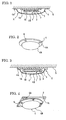
- FIG. 1 is a cross-sectional view showing an embodiment of a vehicle-mounted communication antenna according to the present invention in a state where it is mounted on a vehicle body.
- FIG. 2 is a perspective view of the antenna cover in FIG. 1.
- FIG. 3 is a cross-sectional view showing another embodiment of a vehicle-mounted communication antenna according to the present invention in a state where it is mounted on a vehicle body.
- FIG. 4 is a perspective view of the antenna cover in FIG. 3.
- FIG. 5 is a perspective view of another example of the antenna cover.
- FIG. 6 is a perspective view of still another example of the antenna cover.
- Embodiments of the present invention will be described in detail below with reference to the attached drawings.
- Referring to FIG. 1, there is shown an embodiment of a vehicle-mounted communication antenna according to the present invention; reference character X denotes a vehicle-mounted communication antenna to be mounted on a vehicle for performing communication by an electromagnetic wave. The vehicle-mounted communication antenna X includes an antenna body 3 having an antenna case 1 formed of resin and an
antenna element 2 contained therein, and anantenna cover 4 for protecting the antenna body 3. - The antenna case 1 includes a plate-
shaped attachment part 1A for attaching it to avehicle body 5, and acase body 1B fixed to theattachment part 1A and containing theantenna element 2; the antenna body 3 is designed to be attached to the vehicle by fixing theattachment part 1A to thevehicle body 5 with screws (not shown). Thecase body 1B has a waterproofed structure that prevents water from entering into the inside of the case body that contains theantenna element 2. - The
antenna cover 4, which is in the form of a circular dome, includes acover body 4B in plate form that is placed with a prescribed space over the antenna body 3 mounted on thevehicle body 5, and aflange portion 4A in annular shape that is formed on the circumference of thecover body 4B. Theflange portion 4A has, as shown in FIG. 2,attachment holes 6 formed at prescribed intervals along its circumferential direction for attaching the antenna cover to thevehicle body 5; as shown in FIG. 1, theflange portion 4A of theantenna cover 4 is designed to be detachably attached to thevehicle body 5 with screws (not shown) via theattachment holes 6. - A material used for the
antenna cover 4 may be any one if the material is a dielectric one that can transmit an electromagnetic wave; examples of the material preferably include acrylic resin, polycarbonate rein, ABS (acrylonitrile butadiene styrene) rein and fluorine resin. These resins may be used alone or in combination. - It should be noted that 'can transmit an electromagnetic wave' referred here means that the electromagnetic wave can be received by the
antenna element 2 through theantenna cover 4; each of such states is expressed as 'can transmit an electromagnetic wave'. - The relative permittivity ε of the dielectric material used for the
antenna cover 4 is preferably in the range from 1 to 3. If the relative permittivity ε exceeds 3, a great increase in attenuation amount changes communication characteristics. More preferably, the relative permittivity ε is 1. Only thecover body 4B of theantenna cover 4 may be formed of a dielectric material having the above ranged relative permittivity ε. - According to the present invention described above, the
antenna element 2 is doubly protected by theantenna cover 4 in addition to the antenna case 1; therefore, when the vehicle-mounted communication antenna X is installed in a tire house, theantenna element 2 is not easily damaged even if a stone, foreign object or the like flipped up by the tire strikes on the vehicle-mounted communication antenna X; accordingly, the vehicle-mounted communication antenna X does not easily lose a communication function. - Since the
antenna cover 4 is dome-shaped, it can gain a mechanically high strength even if it is thin in thickness; thus, theantenna cover 4 is not easily brought to destruction even if the stone, foreign object or the like strikes thereon; since there is a prescribedspace 7 between the antenna body 3 and theantenna cover 4, even if the stone, foreign object or the like strikes on theantenna cover 4 to thereby destroy it, the influence of the destruction on the antenna body 3 can be prevented. - The vehicle-mounted communication antenna of a tire condition monitoring device is generally placed above a tire in a tire house; even if the antenna cover 4 drops off due to impact, the damage to the tire can be less because the antenna cover is dome-shaped. Since the employment of the dome shape can make the amount of protrusion of the antenna cover 4 less, the vehicle-mounted communication antenna X can be easily attached above a tire in a tire house.
- The
antenna cover 4 is structured so that it is detachably attached, whereby replacing theantenna cover 4 can be facilitated when it is brought to destruction. - Referring to FIGS. 3 and 4, there is shown another embodiment of a vehicle-mounted communication antenna according to the present invention. The vehicle-mounted communication antenna Y of this embodiment is arranged such that the above-described
antenna cover 4 is attached to the antenna body 3 in the alternative of the attachment of theantenna cover 4 to thevehicle body 5; other structures are the same as in the vehicle-mounted communication antenna X shown in FIG. 1. - The
flange portion 4A of theantenna cover 4 is detachably attached to theattachment part 1A of the antenna case 1 by screws 8 with thecover body 4B of theantenna cover 4 covering thecase body 1B. In the drawing,reference numeral 9 denotes an attachment hole formed in theattachment part 1A of the antenna case 1; the antenna body 3 is designed to be attached to thevehicle body 5 with screws (not shown) passing throughattachment holes 9. - In the embodiment shown in FIGS. 3 and 4, in addition to the above effects, the position of the
antenna cover 4 relative to the antenna body 3 is always fixed, which stabilizes communication characteristics. More specifically, when communication is performed by a radio wave having a very weak transmission strength, the difference of the attachment position of theantenna cover 4 greatly affects on communication characteristics. The attachment of theantenna cover 4 to the antenna body 3 always allows theantenna cover 4 to be attached to the antenna body 3 at the predetermined same optimal position thereof; therefore, stable communication characteristics can be obtained. - Also, the vehicle-mounted communication antenna Y can be mounted on the
vehicle body 5 in a state where theantenna cover 4 is previously attached to the antenna body 3; therefore, the number of the steps and the time of the attachment operation to thevehicle body 4 can be reduced in comparison to those of the vehicle-mounted communication antenna X shown in FIGS. 1 and 2. - In the present invention, the above-described
antenna cover 4 may be structured as shown in FIGS. 5 and 6. Theantenna cover 4 in FIG. 5 includes a circular-dome-shaped cover body 4B having at its center a drain opening (drain means) 10 which can drain water outside that has entered into theantenna cover 4. - The
antenna cover 4 is placed in a tire hose in a state where, as shown in FIGS. 1 and 3, the antenna cover protrudes downward. Therefore, if theantenna cover 4 has water in it, the communication characteristic varies (relative permittivity varies) to badly influence transmitting and receiving when communication is performed by a radio wave having a very weak transmission strength. Even if water enters into theantenna cover 4, it can be drained through the drain opening 10, thus allowing communication characteristics to be always stabilized. As is obvious, theantenna cover 4 may be waterproofed; however, since the attachment operation efficiency thereof decreases, thedrain opening 10 is preferably provided as described above. - The
antenna cover 4 in FIG. 6 has a circular-dome-shaped cover body 4B with a net-like structure, which hasopenings 11 as the drain means. This also allows the same effects as theantenna cover 4 in FIG. 5 to be obtained. - If the
cover body 4B has a net-like structure as shown in FIG. 6 and theantenna cover 4 is attached to the antenna body 3 in such a manner that communication can be performed (an electromagnetic wave can pass) through theopenings 11, theantenna cover 4 may be formed of non-dielectric material such as metal in the alternative of the dielectric material. - It is preferable in terms of communication characteristics that the material, thickness, shape (size of the curved surface of the dome shape), etc. of the above-described
antenna cover 4 be suitably adjusted so that the attenuation amount of the electromagnetic wave is equal to or greater than - 2 dB and is less than 3 dB when it passes through the antenna cover. It should be noted that the reason why the attenuation amount has a minus (that is, amplification) range is that amplification may happen when the attenuation amount of an electromagnetic wave passing through the antenna cover is actually examined, changing the material, thickness or shape.
- In the above embodiments, the
antenna cover 4 is detachably attached with screws; however, there is no limitation thereto; the present invention may employ, for example, a structure such that theantenna cover 4 is locked to thevehicle body 4 or theattachment part 1A of the antenna case 1 via slots, or a structure such that the circular-dome-shaped cover body 4B has an internal thread portion formed in an inner surface of the proximal end portion of the cover body, theattachment part 1A of the antenna case 1 is circularly formed and its outer circumferential surface has an external thread portion, and the internal thread portion of thecover body 4B engages the external thread portion of theattachment part 1A. - The
cover body 4B of theantenna cover 4 may be, for example, elliptical-dome-shaped in the alternative of being circular-dome-shaped. - The vehicle-mounted communication antenna of the present invention may be an antenna for receiving only, an antenna for transmitting only, or an antenna for receiving and transmitting having both functions of receiving and transmitting.
- The present invention is particularly preferably applicable to a vehicle-mounted communication antenna for performing communication by an electromagnetic wave having a frequency band of 300 MHz to 450 MHz, the vehicle-mounted communication antenna being used for a device that can collect information such as air pressure, temperature, etc. in a tire during running with a sensor placed in the tire to monitor a condition of the tire, and being installed in a tire house; however, there is no limitation thereto.
- The vehicle-mounted communication antenna of the present invention having the aforementioned excellent effects can be very effectively utilized as a vehicle-mounted communication antenna to be mounted on a vehicle for performing communication by an electromagnetic wave.
Claims (7)
- A vehicle-mounted communication antenna to be mounted on a vehicle for performing communication by an electromagnetic wave, comprising an antenna body having an antenna case and an antenna element contained in the antenna case, and an antenna cover for protecting the antenna body that can transmit the electromagnetic wave.
- A vehicle-mounted communication antenna according to claim 1, wherein the antenna cover has a dome-shaped cover body that is placed with a prescribed space relative to the antenna body.
- A vehicle-mounted communication antenna according to claim 1 or 2, wherein the antenna cover has a flange portion to be detachably attached to the vehicle.
- A vehicle-mounted communication antenna according to claim 1 or 2, wherein the antenna cover has a flange portion to be detachably attached to the antenna case.
- A vehicle-mounted communication antenna according to any one of claims 1 to 4, wherein the antenna case has a waterproofed structure, and the antenna cover has drain means that can drain water outside which has entered into the antenna cover.
- A vehicle-mounted communication antenna according to any one of claims 1 to 5, wherein the antenna cover is formed of a dielectric material having a relative permittivity ε of 1 to 3.
- A vehicle-mounted communication antenna according to any one of claims 1 to 6, wherein the antenna cover has an attenuation amount that is equal to or greater than -2 dB and is less than 3 dB when the electromagnetic wave passes through the antenna cover.
Applications Claiming Priority (2)
| Application Number | Priority Date | Filing Date | Title |
|---|---|---|---|
| JP2004164551A JP2005348032A (en) | 2004-06-02 | 2004-06-02 | On-vehicle communication antenna |
| PCT/JP2005/010028 WO2005119840A1 (en) | 2004-06-02 | 2005-06-01 | Vehicle-mounted communication antenna |
Publications (3)
| Publication Number | Publication Date |
|---|---|
| EP1753078A1 true EP1753078A1 (en) | 2007-02-14 |
| EP1753078A4 EP1753078A4 (en) | 2008-03-19 |
| EP1753078B1 EP1753078B1 (en) | 2011-08-10 |
Family
ID=35463154
Family Applications (1)
| Application Number | Title | Priority Date | Filing Date |
|---|---|---|---|
| EP05745766A Ceased EP1753078B1 (en) | 2004-06-02 | 2005-06-01 | Vehicle-mounted communication antenna |
Country Status (5)
| Country | Link |
|---|---|
| US (1) | US7705794B2 (en) |
| EP (1) | EP1753078B1 (en) |
| JP (1) | JP2005348032A (en) |
| CN (1) | CN1957505B (en) |
| WO (1) | WO2005119840A1 (en) |
Families Citing this family (18)
| Publication number | Priority date | Publication date | Assignee | Title |
|---|---|---|---|---|
| JP4626547B2 (en) * | 2006-03-22 | 2011-02-09 | 株式会社デンソー | In-vehicle dielectric antenna and method for adjusting resonance frequency of antenna element |
| DE102008046974B4 (en) * | 2008-09-12 | 2013-12-19 | Siemens Aktiengesellschaft | Local coil device for magnetic resonance tomography device |
| JP5177547B2 (en) * | 2008-12-04 | 2013-04-03 | 横河電機株式会社 | Wireless explosion-proof equipment |
| JP5441540B2 (en) * | 2009-07-22 | 2014-03-12 | 株式会社オーディオテクニカ | Boundary microphone |
| IT1395655B1 (en) * | 2009-08-04 | 2012-10-16 | Eltek Spa | MONITORING DEVICE FOR A WHEEL OF A VEHICLE |
| JP5444183B2 (en) * | 2010-10-08 | 2014-03-19 | トヨタ自動車株式会社 | Antenna unit |
| DE102013206519B4 (en) * | 2013-04-12 | 2023-08-17 | Bayerische Motoren Werke Aktiengesellschaft | Antenna system for a vehicle and method for manufacturing such an antenna system |
| US9887453B2 (en) * | 2013-04-29 | 2018-02-06 | Raytheon Company | Ballistic radome with extended field of view |
| US9673517B2 (en) * | 2014-04-30 | 2017-06-06 | Honda Motor Co., Ltd. | Vehicle radar cover assembly and method |
| JP6937245B2 (en) * | 2015-12-16 | 2021-09-22 | テクノUmg株式会社 | Resin parts, radomes and radar devices placed in the path of the beam emitted by the radar device |
| JP6783088B2 (en) | 2016-07-29 | 2020-11-11 | 株式会社ブリヂストン | Sensor case |
| US10581141B2 (en) | 2016-10-21 | 2020-03-03 | DISH Technologies L.L.C. | RF antenna arrangement configured to be a part of a lid to an apparatus |
| US10320055B2 (en) | 2017-04-28 | 2019-06-11 | DISH Technologies L.L.C. | Radio frequency antenna for short range communications |
| IT201700081386A1 (en) * | 2017-07-18 | 2019-01-18 | Magneti Marelli Spa | "System for fixing a telematic module to the roof of a vehicle" |
| KR20190085266A (en) * | 2018-01-10 | 2019-07-18 | 주식회사 만도 | Radar device for vehicle |
| US11201414B2 (en) * | 2018-12-18 | 2021-12-14 | Veoneer Us, Inc. | Waveguide sensor assemblies and related methods |
| US10868365B2 (en) * | 2019-01-02 | 2020-12-15 | Earl Philip Clark | Common geometry non-linear antenna and shielding device |
| US12529788B2 (en) * | 2021-10-07 | 2026-01-20 | Lg Innotek Co., Ltd. | Radar device and driving method therefor |
Family Cites Families (30)
| Publication number | Priority date | Publication date | Assignee | Title |
|---|---|---|---|---|
| US4308540A (en) * | 1980-01-08 | 1981-12-29 | Winegard Company | Compact television antenna system |
| US4609905A (en) * | 1984-05-11 | 1986-09-02 | Eaton Corporation | Tire condition monitoring system |
| JPS623103U (en) * | 1985-06-24 | 1987-01-09 | ||
| US4968984A (en) * | 1987-06-29 | 1990-11-06 | Nissan Motor Company, Limited | Antenna unit for a vehicle |
| JPH02141007A (en) * | 1988-11-21 | 1990-05-30 | Mitsubishi Electric Corp | Micro-strip antenna |
| JPH0374908A (en) * | 1989-08-16 | 1991-03-29 | Toyo Commun Equip Co Ltd | Microstrip antenna of stack type |
| JPH0358012U (en) * | 1989-10-12 | 1991-06-05 | ||
| US5689276A (en) * | 1994-04-07 | 1997-11-18 | Nippon Steel Corporation | Housing for antenna device |
| JP3639845B2 (en) * | 1994-05-30 | 2005-04-20 | 富士通テン株式会社 | Antenna device for receiving satellite and terrestrial radio waves |
| JPH08148916A (en) * | 1994-11-25 | 1996-06-07 | Fuji Elelctrochem Co Ltd | In-vehicle antenna device |
| JPH08162843A (en) * | 1994-12-06 | 1996-06-21 | Sharp Corp | Microstrip antenna device and receiving method using vehicle-mounted microstrip antenna device |
| JPH09223911A (en) * | 1996-02-14 | 1997-08-26 | Toyo Commun Equip Co Ltd | Waterproof ventilation structure of antenna |
| JPH09321515A (en) * | 1996-05-31 | 1997-12-12 | Matsushita Electric Works Ltd | Antenna system |
| JP3255048B2 (en) * | 1996-11-21 | 2002-02-12 | 三菱電機株式会社 | On-board unit antenna device, on-board unit and road-vehicle communication system |
| JP3596215B2 (en) * | 1997-03-04 | 2004-12-02 | 株式会社村田製作所 | Antenna case |
| GB2332568A (en) * | 1997-12-22 | 1999-06-23 | Northern Telecom Ltd | Drain valve for telecommunications enclosure |
| JP2000013127A (en) * | 1998-06-26 | 2000-01-14 | Mitsubishi Electric Corp | Electronics |
| EP0978729A3 (en) * | 1998-08-07 | 2002-03-20 | Hitachi, Ltd. | High-frequency transmitter-receiving apparatus for such an application as vehicle-onboard radar system |
| JP2000252739A (en) * | 1999-03-02 | 2000-09-14 | Toshiba Corp | Antenna device |
| US6474380B1 (en) * | 1999-04-29 | 2002-11-05 | Bridgestone/Firestone North American Tire, Llc | Pneumatic tire and monitoring device including dipole antenna |
| US7331367B2 (en) * | 2000-03-31 | 2008-02-19 | Bridgestone Firestone North American Tire, Llc | Monitoring device and patch assembly |
| JP3632561B2 (en) * | 2000-05-12 | 2005-03-23 | 株式会社デンソー | Air pressure detection device and tire condition monitoring system |
| JP2002325005A (en) * | 2001-04-25 | 2002-11-08 | Alps Electric Co Ltd | Waterproof structure of antenna |
| JP2003063220A (en) | 2001-08-30 | 2003-03-05 | Nippon Seiki Co Ltd | Tire air pressure monitoring device |
| JP2003110327A (en) * | 2001-09-27 | 2003-04-11 | Dx Antenna Co Ltd | Structure of antenna case |
| JP3883847B2 (en) * | 2001-11-19 | 2007-02-21 | 株式会社日立製作所 | In-vehicle signal processor |
| JP2003309409A (en) * | 2002-04-15 | 2003-10-31 | Denso Corp | Mounting structure of embedded antenna for vehicle and mounting method of embedded antenna for vehicle |
| JP2004077399A (en) | 2002-08-22 | 2004-03-11 | Hitachi Ltd | Millimeter wave radar |
| EP1624527B1 (en) * | 2003-04-24 | 2012-05-09 | Asahi Glass Company, Limited | Antenna device |
| JP4050257B2 (en) * | 2004-06-25 | 2008-02-20 | アルプス電気株式会社 | In-vehicle antenna device |
-
2004
- 2004-06-02 JP JP2004164551A patent/JP2005348032A/en active Pending
-
2005
- 2005-06-01 WO PCT/JP2005/010028 patent/WO2005119840A1/en not_active Ceased
- 2005-06-01 US US11/587,872 patent/US7705794B2/en not_active Expired - Fee Related
- 2005-06-01 CN CN2005800168618A patent/CN1957505B/en not_active Expired - Fee Related
- 2005-06-01 EP EP05745766A patent/EP1753078B1/en not_active Ceased
Also Published As
| Publication number | Publication date |
|---|---|
| EP1753078A4 (en) | 2008-03-19 |
| WO2005119840A1 (en) | 2005-12-15 |
| EP1753078B1 (en) | 2011-08-10 |
| JP2005348032A (en) | 2005-12-15 |
| CN1957505B (en) | 2012-03-21 |
| US7705794B2 (en) | 2010-04-27 |
| US20070229374A1 (en) | 2007-10-04 |
| CN1957505A (en) | 2007-05-02 |
Similar Documents
| Publication | Publication Date | Title |
|---|---|---|
| EP1753078B1 (en) | Vehicle-mounted communication antenna | |
| US10850577B2 (en) | Tire comprising a passive transponder and method for reading the data | |
| US6424892B1 (en) | Vehicle surroundings monitoring device | |
| US7310069B2 (en) | Antenna for tire pressure monitoring wheel electronic device | |
| US6357833B1 (en) | Wheel component with cavity for mounting a housing for measurement apparatus | |
| CN102612442B (en) | Transmission device for transmitting information about tire condition and tire condition monitoring system | |
| WO2010073157A4 (en) | Extendable helical antenna for personal communication device | |
| US20080150712A1 (en) | Tire pressure monitoring (tpm) and remote keyless entry (rke) system | |
| CA2993169C (en) | Transmitting device with antenna | |
| EP2062751B1 (en) | Non-attached tire monitoring device | |
| US20070103285A1 (en) | Antenna apparatus disposed in tire | |
| US20060144132A1 (en) | Sensor device for tire | |
| EP2735456B1 (en) | Transmitter apparatus for transmitting tire information, and tire information monitoring system | |
| US6774777B2 (en) | Tire condition monitoring apparatus | |
| WO2016119949A1 (en) | Wireless bearing monitoring device | |
| JP2008154193A (en) | Antenna unit incorporated in tire | |
| EP1506100A1 (en) | Tyre sensor interrogation and valve therefore | |
| US6271797B2 (en) | Combination antenna mount | |
| JP2005241438A (en) | A tire condition detection device, a tire condition monitoring system, and a method for attaching the tire condition detection device to a tire wheel. | |
| US20210053531A1 (en) | Vehicle with a device for passive access control | |
| US8681055B2 (en) | Coupling structure for antenna device | |
| JP2003165316A (en) | Tire internal pressure alarm device | |
| JP2007150823A (en) | In-vehicle wireless receiver | |
| EP1095828A3 (en) | Intruder detection system for a motor vehicle | |
| JP2005206013A (en) | Tire inner pressure alarm device and method for fixing tire inner pressure alarm device |
Legal Events
| Date | Code | Title | Description |
|---|---|---|---|
| PUAI | Public reference made under article 153(3) epc to a published international application that has entered the european phase |
Free format text: ORIGINAL CODE: 0009012 |
|
| 17P | Request for examination filed |
Effective date: 20061121 |
|
| AK | Designated contracting states |
Kind code of ref document: A1 Designated state(s): DE FR |
|
| DAX | Request for extension of the european patent (deleted) | ||
| RBV | Designated contracting states (corrected) |
Designated state(s): DE FR |
|
| A4 | Supplementary search report drawn up and despatched |
Effective date: 20080215 |
|
| 17Q | First examination report despatched |
Effective date: 20100426 |
|
| GRAP | Despatch of communication of intention to grant a patent |
Free format text: ORIGINAL CODE: EPIDOSNIGR1 |
|
| GRAS | Grant fee paid |
Free format text: ORIGINAL CODE: EPIDOSNIGR3 |
|
| GRAA | (expected) grant |
Free format text: ORIGINAL CODE: 0009210 |
|
| RIN1 | Information on inventor provided before grant (corrected) |
Inventor name: SHIMURA, KAZUHIRO,C/O THE YOKOHAMA RUBBER CO. LTD. |
|
| AK | Designated contracting states |
Kind code of ref document: B1 Designated state(s): DE FR |
|
| REG | Reference to a national code |
Ref country code: DE Ref legal event code: R096 Ref document number: 602005029443 Country of ref document: DE Effective date: 20111006 |
|
| PLBE | No opposition filed within time limit |
Free format text: ORIGINAL CODE: 0009261 |
|
| STAA | Information on the status of an ep patent application or granted ep patent |
Free format text: STATUS: NO OPPOSITION FILED WITHIN TIME LIMIT |
|
| 26N | No opposition filed |
Effective date: 20120511 |
|
| REG | Reference to a national code |
Ref country code: DE Ref legal event code: R097 Ref document number: 602005029443 Country of ref document: DE Effective date: 20120511 |
|
| REG | Reference to a national code |
Ref country code: FR Ref legal event code: PLFP Year of fee payment: 12 |
|
| REG | Reference to a national code |
Ref country code: FR Ref legal event code: PLFP Year of fee payment: 13 |
|
| PGFP | Annual fee paid to national office [announced via postgrant information from national office to epo] |
Ref country code: DE Payment date: 20170523 Year of fee payment: 13 Ref country code: FR Payment date: 20170511 Year of fee payment: 13 |
|
| REG | Reference to a national code |
Ref country code: DE Ref legal event code: R119 Ref document number: 602005029443 Country of ref document: DE |
|
| PG25 | Lapsed in a contracting state [announced via postgrant information from national office to epo] |
Ref country code: DE Free format text: LAPSE BECAUSE OF NON-PAYMENT OF DUE FEES Effective date: 20190101 Ref country code: FR Free format text: LAPSE BECAUSE OF NON-PAYMENT OF DUE FEES Effective date: 20180630 |