EP1753073A2 - Compliant, internally cooled antenna apparatus and method - Google Patents
Compliant, internally cooled antenna apparatus and method Download PDFInfo
- Publication number
- EP1753073A2 EP1753073A2 EP06016548A EP06016548A EP1753073A2 EP 1753073 A2 EP1753073 A2 EP 1753073A2 EP 06016548 A EP06016548 A EP 06016548A EP 06016548 A EP06016548 A EP 06016548A EP 1753073 A2 EP1753073 A2 EP 1753073A2
- Authority
- EP
- European Patent Office
- Prior art keywords
- mandrel
- core component
- component
- antenna system
- leaf spring
- Prior art date
- Legal status (The legal status is an assumption and is not a legal conclusion. Google has not performed a legal analysis and makes no representation as to the accuracy of the status listed.)
- Granted
Links
Images


Classifications
-
- H—ELECTRICITY
- H01—ELECTRIC ELEMENTS
- H01Q—ANTENNAS, i.e. RADIO AERIALS
- H01Q21/00—Antenna arrays or systems
- H01Q21/0006—Particular feeding systems
- H01Q21/0025—Modular arrays
-
- H—ELECTRICITY
- H01—ELECTRIC ELEMENTS
- H01Q—ANTENNAS, i.e. RADIO AERIALS
- H01Q1/00—Details of, or arrangements associated with, antennas
- H01Q1/02—Arrangements for de-icing; Arrangements for drying-out ; Arrangements for cooling; Arrangements for preventing corrosion
-
- H—ELECTRICITY
- H01—ELECTRIC ELEMENTS
- H01Q—ANTENNAS, i.e. RADIO AERIALS
- H01Q3/00—Arrangements for changing or varying the orientation or the shape of the directional pattern of the waves radiated from an antenna or antenna system
- H01Q3/26—Arrangements for changing or varying the orientation or the shape of the directional pattern of the waves radiated from an antenna or antenna system varying the relative phase or relative amplitude of energisation between two or more active radiating elements; varying the distribution of energy across a radiating aperture
Definitions
- the present invention relates to phased array antenna systems, and more particularly to a longitudinally compliant, internally cooled phased array antenna system in which a cooling medium is flowed through an interior area of a core component to cool the core component and other electronic components supported on the core component.
- Phased array antennas are used in a variety of commercial and military applications. Typically, these antennas include hundreds of transmit/receive radiating elements that are supported adjacent one surface of a core component.
- the core component is made from a thermally conductive material such as aluminum.
- MMICs monolithic microwave integrated circuits
- phase shifters phase shifters and other components. These components generate heat which is radiated through thermally conductive standoffs that are used to support the ceramic chip carrier boards closely adjacent the core component.
- MMICs monolithic microwave integrated circuits
- the core component itself is supported on a cold plate.
- the cold plate has internally formed channels or tubes integrally formed with it to circulate a fluid through the cold plate. The fluid helps to draw heat from the core component, which in turn enables the ceramic chip carrier boards to be cooled.
- the present invention is directed to a phased array antenna system in which a cooling medium is circulated through an elongated core component of the system to even more efficiently cool the electronic components of the antenna system during use.
- the core component also includes a leaf spring-like structure formed at a lower portion of the core component that allows the lower portion to flex slightly, relative to the remainder of the core component, when the core component is secured to a printed wiring board subassembly. This enables excellent electrical contact to be maintained with the printed wiring board subassembly along the full length of the core component.
- the core component forms an elongated mandrel having both a cooling medium carrying channel formed inside, as well as a hollowed out area for allowing air to circulate within the inside area of the mandrel.
- the core component has a length sufficient to support a plurality of electronic component boards in side-by-side fashion, on opposing side surfaces of the mandrel.
- the core component is formed from a solid block of aluminum.
- the leaf spring-like structure is formed by removing material from an interior area of the mandrel, as well as from opposing side portions, such that a plurality of U-shaped leaf spring-like sections of material are formed.
- the U-shaped leaf spring-like sections of material enable one end portion of the mandrel to be compliant and thus to flex slightly along its length as the mandrel is secured to a printed wiring board.
- a multi-layer flexible interconnect circuit assembly is coupled to the one end of the mandrel.
- the compliant section of the mandrel ensures that the multi-layer flexible interconnect circuit assembly makes excellent contact with conductive traces on a printed wiring board, along its full length, once the mandrel is secured to the printed wiring board. This ensures electrical communication between contacts on the printed wiring board and circuit traces formed on the flexible interconnect circuit assembly.
- Figure 1 is a perspective view of a preferred embodiment of an antenna system in accordance with the present invention.
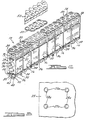
- Figure 2 is a partially exploded perspective view of one module row of the antenna of Figure 1;
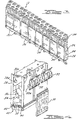
- Figure 3 is a view of the opposite side of the module row of Figure 2;
- Figure 4 is an exploded perspective view of a portion of the module row of Figure 3;
- Figure 5 is a plan view of a portion of the mandrel in accordance with arrows 5 in Figure 2;
- Figure 6 is a perspective view of a lower portion of the module row of Figure 2 with the fasteners omitted;
- Figure 7 is an end view of a portion of the module row of Figure 2.
- an antenna system 10 in accordance with the preferred embodiment of the present invention is shown.
- the antenna system 10 is illustrated as a phased array antenna system having a plurality of identical antenna module rows 12, each of which comprises a plurality of eight element phased array antenna modules 16 supported on a printed wiring board 18.
- each antenna module row 12 has 32 elements.
- Each module row 12 is coupled at opposite ends to a pair of manifolds 20 and 22.
- Manifold 20 forms an input manifold that carries a cooling medium, for example a fluid such as water, an inert gas, or any other flowable medium capable of drawing heat from the module rows 12, from a supply conduit 24 to supply the cooling medium to each module row 12.
- a cooling medium for example a fluid such as water, an inert gas, or any other flowable medium capable of drawing heat from the module rows 12, from a supply conduit 24 to supply the cooling medium to each module row 12.
- Manifold 22 forms an output manifold that collects the cooling medium flowing through each module row 12 and returns the cooling medium to a radiator, heat exchanger or supply source coupled to conduit 26. In this manner, the cooling medium flowing through each module row 12 is used to cool the electronic components on each of the modules 16. This provides even more efficient cooling of the electronic components on each antenna module 16. While only eight module rows 12 are shown, a greater or lesser number of module rows 12 could be implemented to suit the needs of a specific application. In the example embodiment of Figure 1, the system 10 forms a 256 element phased array antenna.
- one module row 12 is shown in a partially exploded prospective fashion.
- the printed wiring board 18 has been omitted to better illustrate the structure of the antenna modules 16.
- each module row 12 is formed by an elongated, thermally conductive core component in the form of a metallic mandrel 28 having a plurality of components supported thereon in thermal communication with the mandrel 28 ( Figures 2 and 3).
- the mandrel 28 is formed by a single piece of aluminum stock.
- the mandrel 28 supports a plurality of ceramic chip carrier assemblies 30 adjacent one another along one side surface of the mandrel 28, and a corresponding plurality of chip carrier component assemblies 30 on an opposing side surface of the mandrel 28 ( Figure 3).
- a plurality of conventional circulator assemblies 32 are also disposed on each side of the mandrel 28. Each circulator assembly 32 is associated with a single one of the chip carrier assemblies 30.
- AIPWBs 34 Eight element antenna integrated printed wiring boards (AIPWBs) 34 are disposed on an upper surface of the mandrel 28 ( Figure 4).
- Four flexible interconnect circuit assemblies 36 are secured at a lower end of the mandrel 28 and are electrically coupled to the ceramic chip carrier assemblies 30 using conventional wire bonds 30a.
- Each flexible interconnect circuit assembly 36 may be secured by bonding, as generally described in U.S. application serial no. 10/991,291, filed November 17, 2004 , and assigned to the Boeing Company, and incorporated by reference herein.
- Each AIPWP 32 provides eight dual polarization radiating elements, as well as an interface to DC logic and power subsystems (not shown) associated with the antenna.
- each mandrel 28 includes a pair of leaf spring-like structures 38 formed at a lower end thereof.
- the leaf spring-like structure 38 is formed by removing material on the interior area of the mandrel 28, as well as along lower exterior side portions 40 of the mandrel, so that the material left forms a generally sideways-facing U-shaped structure. Cut-outs 46 are also formed along the lower side portions 40 of the mandrel 28 such that a plurality of independently compliant sections 47 are formed on the mandrel 28.
- the entire length of the lower surface portion of the mandrel 28 can be held securely against the printed wiring board 18. This eliminates the possibility of undulations in the surface of the printed wiring board 18, or a slight curvature or undulations of the mandrel 28, from preventing electrical content from being made between surface traces on the printed wiring board 18 and the flexible interconnect circuit assemblies 36, at one or more points along the length of the mandrel 28.
- the AIPWBs 34 may be formed in accordance with the teachings of U.S. Patent Application Serial No. 10/200,088, filed July 19, 2002 ; U.S. Patent No. 6,670,930, issued on December 30, 2003 ; and U.S. Patent No. 6,580,402 , issued on June 71, 2003, each of which are hereby incorporated by reference into the present application, and each of which are assigned to The Boeing Company.
- the circulator subassemblies 32 each comprise four channel open (i.e., quad) circulators that are commercially available.
- the circulator subassemblies 32 are in electrical communication with associated ceramic chip carrier subassembly boards 30.
- each circulator subassembly 32 includes four permanent magnets 32a that project through four corresponding holes 28a in the mandrel 28.
- each AIPWB 34 is positioned against a conventional, mechanically compliant spring assembly 50 that forms a thin, conductive layer for making electrical contact with a conventional honeycomb wave guide component 52 that covers each of the AIPWBs 34.
- Alignment pins projecting from the mandrel 28 through each of the AIPWBs 34 enable precise positioning of the honeycomb wave guide 52 and the spring assembly 50 over each of the AIPWBs 34.
- the mandrel 28 includes a hollowed-out area 54 and a cooling medium passageway 56.
- Fastening elements 48 and 50 form attachment posts that can be threaded into openings 60 (in Figure 6) in the mandrel 28 to enable attachment of the mandrel 28 to the printed wiring board 18.
- Threaded nuts 62 ( Figure 7) may be used to accomplish securing of the mandrel 28 to the printed wiring board 18.
- mandrel 28 of Figures 2 and 3 is illustrated as a single section of metallic material, the mandrel 28 could just as readily be formed in two or more sections that are secured together to form an elongated subassembly.
- forming the mandrel 28 from a single length of material eliminates the need for using seals, gaskets, etc., that would otherwise be needed to seal two or more sections of the mandrel together to ensure that the cooling medium flowing through the entire mandrel does not leak at the interfaces of adjacent mandrel sections.
- the compliant leaf spring-like structures 38 enable a single, elongated length of material to be used while still permitting each module section 16 to be secured flush against the outer surface of the printed wiring board 18.
- Each of the ceramic chip carrier boards 30 are preferably secured via thermally conductive adhesive to the mandrel 28. Suitable electrically conductive adhesives are commercially available.
- each slot 46 extends upwardly past the U-shaped leaf spring-like structures 38.
- the slots 46 in combination with the leaf spring-like structures 38, enable the length designated by dash line 66, representing one compliant section 47, to flex independently of adjacent compliant sections 47 along the length of the mandrel 28 when the mandrel 28 is secured to the printed wiring board 18.
- the mandrel 28 is shown clamped securely down to the printed wiring board 18.
- the flexible interconnect circuit 36 makes electrical contact with traces on the upper surface 18a of the printed wiring board 18.
- the flexing of the lower portion 42 of the mandrel 28 does not affect the flow of the cooling medium through the passageway 56, since each compliant portion 47 of the mandrel 28 is independently secured to the printed wiring board 18.
- the mandrel 28 can form slight undulations or a slight curvature along its length that conforms to undulations and/or a slight curvature of the printed wiring board 18, to thus ensure that full contact is made along the entire length of the flexible interconnect circuit 36 and the upper surface 18a of the printed wiring board 18.
- the system 10 of the present invention thus enables an elongated core component of a phased array antenna module to be secured along its full length to a printed circuit assembly while ensuring that proper electrical contact is made along the full length of the core component with the printed wiring board to which it is secured.
- the internal cooling passageway incorporated into the mandrel 28 allows even more efficient cooling of the ceramic chip carrier boards used with phased array antenna systems, since the cooling medium is flowed very close to the source of the heat being generated in the module (i.e., the ceramic chip carrier boards).
- thermoly conductive material for example, aluminum
- the use of a single length of thermally conductive material (for example, aluminum) to form the mandrel further eliminates the need for seals or gaskets to be employed, if the mandrel was to be formed in two or more independent sections and then secured together to form a single mandrel assembly.
Landscapes
- Variable-Direction Aerials And Aerial Arrays (AREA)
- Details Of Aerials (AREA)
Abstract
Description
- The present invention relates to phased array antenna systems, and more particularly to a longitudinally compliant, internally cooled phased array antenna system in which a cooling medium is flowed through an interior area of a core component to cool the core component and other electronic components supported on the core component.
- Phased array antennas are used in a variety of commercial and military applications. Typically, these antennas include hundreds of transmit/receive radiating elements that are supported adjacent one surface of a core component. Typically, the core component is made from a thermally conductive material such as aluminum. Also supported on the core component is a plurality of ceramic chip carrier boards that support a plurality of monolithic microwave integrated circuits (MMICs), phase shifters and other components. These components generate heat which is radiated through thermally conductive standoffs that are used to support the ceramic chip carrier boards closely adjacent the core component. In previously developed systems, the core component itself is supported on a cold plate. The cold plate has internally formed channels or tubes integrally formed with it to circulate a fluid through the cold plate. The fluid helps to draw heat from the core component, which in turn enables the ceramic chip carrier boards to be cooled.
- While the above arrangement has proven to be successful in many applications, it would nevertheless be desirable to provide even more efficient cooling of the ceramic chip carrier and its components. Increased cooling ability is expected to become important as phased array antennas support even greater numbers of radiating elements and associated MMICs, phase shifters, etc., that will generate even greater amounts of heat that will need to be dissipated.
- Thus, there remains a need to even further improve the cooling of a phased array module using a cooling medium, but which does not significantly complicate the construction of a phased array antenna, nor which limits the number of radiating/reception elements that may be employed or otherwise interferes with mounting of the ceramic chip carrier boards on a module core component.
- The present invention is directed to a phased array antenna system in which a cooling medium is circulated through an elongated core component of the system to even more efficiently cool the electronic components of the antenna system during use. The core component also includes a leaf spring-like structure formed at a lower portion of the core component that allows the lower portion to flex slightly, relative to the remainder of the core component, when the core component is secured to a printed wiring board subassembly. This enables excellent electrical contact to be maintained with the printed wiring board subassembly along the full length of the core component.
- In one preferred implementation the core component forms an elongated mandrel having both a cooling medium carrying channel formed inside, as well as a hollowed out area for allowing air to circulate within the inside area of the mandrel. The core component has a length sufficient to support a plurality of electronic component boards in side-by-side fashion, on opposing side surfaces of the mandrel.
- In one preferred implementation the core component is formed from a solid block of aluminum. The leaf spring-like structure is formed by removing material from an interior area of the mandrel, as well as from opposing side portions, such that a plurality of U-shaped leaf spring-like sections of material are formed. The U-shaped leaf spring-like sections of material enable one end portion of the mandrel to be compliant and thus to flex slightly along its length as the mandrel is secured to a printed wiring board. A multi-layer flexible interconnect circuit assembly is coupled to the one end of the mandrel. The compliant section of the mandrel ensures that the multi-layer flexible interconnect circuit assembly makes excellent contact with conductive traces on a printed wiring board, along its full length, once the mandrel is secured to the printed wiring board. This ensures electrical communication between contacts on the printed wiring board and circuit traces formed on the flexible interconnect circuit assembly.
- The features, functions, and advantages can be achieved independently in various embodiments of the present inventions or may be combined in yet other embodiments.
- The present invention will become more fully understood from the detailed description and the accompanying drawings, wherein:
- Figure 1 is a perspective view of a preferred embodiment of an antenna system in accordance with the present invention;
- Figure 2 is a partially exploded perspective view of one module row of the antenna of Figure 1;
- Figure 3 is a view of the opposite side of the module row of Figure 2;
- Figure 4 is an exploded perspective view of a portion of the module row of Figure 3;
- Figure 5 is a plan view of a portion of the mandrel in accordance with arrows 5 in Figure 2;
- Figure 6 is a perspective view of a lower portion of the module row of Figure 2 with the fasteners omitted; and
- Figure 7 is an end view of a portion of the module row of Figure 2.
- The following description of the preferred embodiment(s) is merely exemplary in nature and is in no way intended to limit the invention, its application, or uses.
- Referring to Figure 1, an antenna system 10 in accordance with the preferred embodiment of the present invention is shown. The antenna system 10 is illustrated as a phased array antenna system having a plurality of identical
antenna module rows 12, each of which comprises a plurality of eight element phasedarray antenna modules 16 supported on a printedwiring board 18. Thus, eachantenna module row 12 has 32 elements. Eachmodule row 12 is coupled at opposite ends to a pair ofmanifolds module rows 12, from a supply conduit 24 to supply the cooling medium to eachmodule row 12. Manifold 22 forms an output manifold that collects the cooling medium flowing through eachmodule row 12 and returns the cooling medium to a radiator, heat exchanger or supply source coupled to conduit 26. In this manner, the cooling medium flowing through eachmodule row 12 is used to cool the electronic components on each of themodules 16. This provides even more efficient cooling of the electronic components on eachantenna module 16. While only eightmodule rows 12 are shown, a greater or lesser number ofmodule rows 12 could be implemented to suit the needs of a specific application. In the example embodiment of Figure 1, the system 10 forms a 256 element phased array antenna. - Referring to Figure 2, one
module row 12 is shown in a partially exploded prospective fashion. The printedwiring board 18 has been omitted to better illustrate the structure of theantenna modules 16. - Referring to Figures 2-4, each
module row 12 is formed by an elongated, thermally conductive core component in the form of ametallic mandrel 28 having a plurality of components supported thereon in thermal communication with the mandrel 28 (Figures 2 and 3). In one preferred form, themandrel 28 is formed by a single piece of aluminum stock. Themandrel 28 supports a plurality of ceramic chip carrier assemblies 30 adjacent one another along one side surface of themandrel 28, and a corresponding plurality of chip carrier component assemblies 30 on an opposing side surface of the mandrel 28 (Figure 3). A plurality of conventional circulator assemblies 32 are also disposed on each side of themandrel 28. Each circulator assembly 32 is associated with a single one of thechip carrier assemblies 30. Eight element antenna integrated printed wiring boards (AIPWBs) 34 are disposed on an upper surface of the mandrel 28 (Figure 4). Four flexibleinterconnect circuit assemblies 36 are secured at a lower end of themandrel 28 and are electrically coupled to the ceramicchip carrier assemblies 30 using conventional wire bonds 30a. Each flexibleinterconnect circuit assembly 36 may be secured by bonding, as generally described inU.S. application serial no. 10/991,291, filed November 17, 2004 - Referring to Figures 2, 5 and 7, it is a principal advantage of the antenna system 10 that each
mandrel 28 includes a pair of leaf spring-like structures 38 formed at a lower end thereof. The leaf spring-like structure 38 is formed by removing material on the interior area of themandrel 28, as well as along lowerexterior side portions 40 of the mandrel, so that the material left forms a generally sideways-facing U-shaped structure. Cut-outs 46 are also formed along thelower side portions 40 of themandrel 28 such that a plurality of independentlycompliant sections 47 are formed on themandrel 28. When themandrel 28 is secured to the printed wiring board 18 (Figure 1) via fastening elements 48 and 50 (Figures 2 and 7), the entire length of the lower surface portion of themandrel 28 can be held securely against the printedwiring board 18. This eliminates the possibility of undulations in the surface of the printedwiring board 18, or a slight curvature or undulations of themandrel 28, from preventing electrical content from being made between surface traces on the printedwiring board 18 and the flexibleinterconnect circuit assemblies 36, at one or more points along the length of themandrel 28. - With further reference to Figures 2 and 3, the
AIPWBs 34 may be formed in accordance with the teachings ofU.S. Patent Application Serial No. 10/200,088, filed July 19, 2002 U.S. Patent No. 6,670,930, issued on December 30, 2003 ; andU.S. Patent No. 6,580,402 , issued on June 71, 2003, each of which are hereby incorporated by reference into the present application, and each of which are assigned to The Boeing Company. - The circulator subassemblies 32 each comprise four channel open (i.e., quad) circulators that are commercially available. The circulator subassemblies 32 are in electrical communication with associated ceramic chip
carrier subassembly boards 30. Referring to Figures 2 and 5, each circulator subassembly 32 includes four permanent magnets 32a that project through four corresponding holes 28a in themandrel 28. Thus, there are 16 circulators for each eightelement antenna module 16. - Referring further to Figure 2, each AIPWB 34 is positioned against a conventional, mechanically
compliant spring assembly 50 that forms a thin, conductive layer for making electrical contact with a conventional honeycombwave guide component 52 that covers each of theAIPWBs 34. Alignment pins (not shown) projecting from themandrel 28 through each of theAIPWBs 34 enable precise positioning of thehoneycomb wave guide 52 and thespring assembly 50 over each of theAIPWBs 34. - Referring further to Figures 2 and 3, the
mandrel 28 includes a hollowed-out area 54 and a coolingmedium passageway 56. Fasteningelements 48 and 50 form attachment posts that can be threaded into openings 60 (in Figure 6) in themandrel 28 to enable attachment of themandrel 28 to the printedwiring board 18. Threaded nuts 62 (Figure 7) may be used to accomplish securing of themandrel 28 to the printedwiring board 18. - While the
mandrel 28 of Figures 2 and 3 is illustrated as a single section of metallic material, themandrel 28 could just as readily be formed in two or more sections that are secured together to form an elongated subassembly. However, forming themandrel 28 from a single length of material eliminates the need for using seals, gaskets, etc., that would otherwise be needed to seal two or more sections of the mandrel together to ensure that the cooling medium flowing through the entire mandrel does not leak at the interfaces of adjacent mandrel sections. The compliant leaf spring-like structures 38 enable a single, elongated length of material to be used while still permitting eachmodule section 16 to be secured flush against the outer surface of the printedwiring board 18. - Each of the ceramic
chip carrier boards 30 are preferably secured via thermally conductive adhesive to themandrel 28. Suitable electrically conductive adhesives are commercially available. - Referring further to Figure 6, a bottom surface of the
mandrel 28 can be seen in greater detail. The depth of eachslot 46 extends upwardly past the U-shaped leaf spring-like structures 38. Thus, theslots 46, in combination with the leaf spring-like structures 38, enable the length designated by dash line 66, representing onecompliant section 47, to flex independently of adjacentcompliant sections 47 along the length of themandrel 28 when themandrel 28 is secured to the printedwiring board 18. - Referring further to Figure 7, the
mandrel 28 is shown clamped securely down to the printedwiring board 18. Theflexible interconnect circuit 36 makes electrical contact with traces on the upper surface 18a of the printedwiring board 18. The flexing of thelower portion 42 of themandrel 28 does not affect the flow of the cooling medium through thepassageway 56, since eachcompliant portion 47 of themandrel 28 is independently secured to the printedwiring board 18. Themandrel 28 can form slight undulations or a slight curvature along its length that conforms to undulations and/or a slight curvature of the printedwiring board 18, to thus ensure that full contact is made along the entire length of theflexible interconnect circuit 36 and the upper surface 18a of the printedwiring board 18. - The system 10 of the present invention thus enables an elongated core component of a phased array antenna module to be secured along its full length to a printed circuit assembly while ensuring that proper electrical contact is made along the full length of the core component with the printed wiring board to which it is secured. The internal cooling passageway incorporated into the
mandrel 28 allows even more efficient cooling of the ceramic chip carrier boards used with phased array antenna systems, since the cooling medium is flowed very close to the source of the heat being generated in the module (i.e., the ceramic chip carrier boards). The use of a single length of thermally conductive material (for example, aluminum) to form the mandrel further eliminates the need for seals or gaskets to be employed, if the mandrel was to be formed in two or more independent sections and then secured together to form a single mandrel assembly. - While various preferred embodiments have been described, those skilled in the art will recognize modifications or variations which might be made without departing from the inventive concept. The examples illustrate the invention and are not intended to limit it. Therefore, the description and claims should be interpreted liberally with only such limitation as is necessary in view of the pertinent prior art.
Claims (18)
- An antenna system (10) comprising:an elongated mandrel (28) for supporting a plurality of electronics subassemblies;the mandrel (28) having material removed at one end to form a plurality of leaf spring like sections (38);each said leaf spring like section (38) enabling a subsection (42) of the mandrel to be able to flex relative to other subsections such that the mandrel (28) forms a conformable support member that can be secured to an external electrical component and conform to a surface curvature of the external electrical component.
- The antenna system of claim 1, wherein said leaf spring like sections (38) form opposing U-shaped leaf spring like sections (38) along a common end of said mandrel (28).
- The antenna system of claim 2, wherein said leaf spring like sections (38) further define cut-outs (46); and
said antenna system (10) further including at least one flexible electrical interconnect assembly (36) that is disposed over said end of said mandrel (28). - The antenna system of claim 3, wherein the mandrel (28) comprises a length of metallic material having a hollowed out portion for receiving a flowing cooling medium to cool the mandrel (28).
- The antenna system of claim 4, wherein the mandrel (28) further comprises a hollowed area (54) adjacent the hollowed out portion for allowing air flow circulation through the mandrel (28).
- The antenna system of claim 5, further comprising an antenna integrated printed wiring board (34) having a plurality of radiating elements mounted to a surface of said mandrel (28) opposite said end along which said leaf spring like sections (38) are formed.
- An antenna system (10) comprising:an elongated mandrel (28) for supporting a plurality of electronic printed wiring boards (18) along a side portion (40) thereof;the mandrel (28) having material removed at opposing sides of one end to form a plurality of leaf spring like sections (38) along a length thereof;each said leaf spring like section (38) enabling a subsection (42) of the mandrel to be able to flex relative to other subsections such that the mandrel (28) forms a conformable support member that can be secured to an external electrical component and conform to a surface curvature of the external electrical component; andthe mandrel (28) further including a fluid passageway (56) for enabling a cooling medium to be circulated through the mandrel (28) to assist in cooling the mandrel (28) during operating of the antenna system (10).
- The antenna system of claim 7, further comprising a plurality of electronic printed wiring boards (18) secured to opposite side surfaces of the mandrel (28) and in thermal communication with the mandrel (28).
- The antenna system of claim 7, further comprising a plurality of antenna wiring boards (18) each having a plurality of radiating elements, and being supported on a surface of said mandrel (28) opposite to said one end, and in electrical communication with an associated one of said electronic printed wiring boards.
- The antenna system of claim 7, further comprising a flexible interconnect assembly (36) supported on said one end of said mandrel (28) for enabling electrical communication with an external electrical circuit component.
- An antenna system comprising:a thermally conductive core component, the core component having an internal flow passage;an electronic component supported from the core component in a manner to transmit heat generated by the electronic component to the core component; anda cooling medium in communication with the core component for circulating a cooling medium through the core component to absorb and carry away heat absorbed by the core component, to thus cool the electronic component.
- The system of claim 11, further comprising:a core component having material removed from one end thereof to form a compliant end portion defined by at least one slot;a flexible electrical circuit interconnect disposed at least partially within the slot, and in electrical communication with said electronic component; anda printed wiring board (18) in communication with said flexible electrical circuit interconnect.
- The system of claim 11 or 12, wherein a manifold (20, 22) comprises a first manifold portion (20) coupled to a first side of said core component for supplying said cooling medium into said core component, and a second manifold portion (22) for receiving said cooling medium after said cooling medium has circulated through said core component.
- The system of one of claims 11 to 13, wherein said core component comprises an elongated component for supporting a plurality of electronic components in side by side fashion therefrom.
- The system of claim 14, wherein said one end of said module includes a plurality of slots (46) for defining a plurality of distinct compliant end portions.
- The system of one of claims 11 to 15, wherein said core component further includes a plurality of secondary internal passages for permitting airflow therethrough.
- The system of one of claims 11 to 16, wherein said core component is comprised of a single piece of aluminum.
- A method for forming a phased array antenna (10), the method comprising:forming a metallic material into an elongated support mandrel (28);forming a hollowed area (54) in the mandrel (28);forming a pair of opposing slots (46), in sections, at one end of the mandrel (28), and along a length of the mandrel (28) such that a plurality of independent, flexible sections (42) are formed that enable the mandrel (28) to be secured to an undulating component while making contact with said undulating component along substantially an entire length of the mandrel (28); andsecuring a plurality of electronic components to side surfaces of the mandrel.
Applications Claiming Priority (1)
| Application Number | Priority Date | Filing Date | Title |
|---|---|---|---|
| US11/200,291 US7443354B2 (en) | 2005-08-09 | 2005-08-09 | Compliant, internally cooled antenna apparatus and method |
Publications (3)
| Publication Number | Publication Date |
|---|---|
| EP1753073A2 true EP1753073A2 (en) | 2007-02-14 |
| EP1753073A3 EP1753073A3 (en) | 2007-04-11 |
| EP1753073B1 EP1753073B1 (en) | 2009-12-30 |
Family
ID=37084614
Family Applications (1)
| Application Number | Title | Priority Date | Filing Date |
|---|---|---|---|
| EP06016548A Expired - Lifetime EP1753073B1 (en) | 2005-08-09 | 2006-08-08 | Compliant, internally cooled antenna apparatus and method |
Country Status (4)
| Country | Link |
|---|---|
| US (1) | US7443354B2 (en) |
| EP (1) | EP1753073B1 (en) |
| AT (1) | ATE453935T1 (en) |
| DE (1) | DE602006011399D1 (en) |
Cited By (4)
| Publication number | Priority date | Publication date | Assignee | Title |
|---|---|---|---|---|
| US7417598B2 (en) | 2006-11-08 | 2008-08-26 | The Boeing Company | Compact, low profile electronically scanned antenna |
| WO2009045939A2 (en) | 2007-10-01 | 2009-04-09 | Raytheon Company | Remote cooling of a phased array antenna |
| WO2010071724A1 (en) * | 2008-12-19 | 2010-06-24 | Raytheon Company | Air cooling for a phased array radar |
| FR2941818A1 (en) * | 2009-01-30 | 2010-08-06 | Thales Sa | Active and electronic scanning type network antenna for use in radar, has microwave frequency distribution channels linked between distribution unit and module, each having distribution sub channels to transport signal to radiating element |
Families Citing this family (26)
| Publication number | Priority date | Publication date | Assignee | Title |
|---|---|---|---|---|
| US9019166B2 (en) | 2009-06-15 | 2015-04-28 | Raytheon Company | Active electronically scanned array (AESA) card |
| US9172145B2 (en) | 2006-09-21 | 2015-10-27 | Raytheon Company | Transmit/receive daughter card with integral circulator |
| US7671696B1 (en) * | 2006-09-21 | 2010-03-02 | Raytheon Company | Radio frequency interconnect circuits and techniques |
| US8279131B2 (en) * | 2006-09-21 | 2012-10-02 | Raytheon Company | Panel array |
| NL1035878C (en) * | 2008-08-28 | 2010-03-11 | Thales Nederland Bv | An array antenna comprising means to establish galvanic contacts between its radiator elements while allowing for their thermal expansion. |
| US7859835B2 (en) * | 2009-03-24 | 2010-12-28 | Allegro Microsystems, Inc. | Method and apparatus for thermal management of a radio frequency system |
| US8045329B2 (en) * | 2009-04-29 | 2011-10-25 | Raytheon Company | Thermal dissipation mechanism for an antenna |
| US8537552B2 (en) | 2009-09-25 | 2013-09-17 | Raytheon Company | Heat sink interface having three-dimensional tolerance compensation |
| US8508943B2 (en) | 2009-10-16 | 2013-08-13 | Raytheon Company | Cooling active circuits |
| US8537059B2 (en) * | 2009-11-20 | 2013-09-17 | Raytheon Company | Cooling system for panel array antenna |
| US8659901B2 (en) * | 2010-02-04 | 2014-02-25 | P-Wave-Holdings, LLC | Active antenna array heatsink |
| US8427371B2 (en) | 2010-04-09 | 2013-04-23 | Raytheon Company | RF feed network for modular active aperture electronically steered arrays |
| US8279604B2 (en) | 2010-08-05 | 2012-10-02 | Raytheon Company | Cooling system for cylindrical antenna |
| US8363413B2 (en) | 2010-09-13 | 2013-01-29 | Raytheon Company | Assembly to provide thermal cooling |
| US8810448B1 (en) | 2010-11-18 | 2014-08-19 | Raytheon Company | Modular architecture for scalable phased array radars |
| US8355255B2 (en) | 2010-12-22 | 2013-01-15 | Raytheon Company | Cooling of coplanar active circuits |
| US8803759B1 (en) * | 2011-06-21 | 2014-08-12 | Lockheed Martin Corporation | Method of internal mechanical connection for joined phased array sections |
| US9124361B2 (en) | 2011-10-06 | 2015-09-01 | Raytheon Company | Scalable, analog monopulse network |
| IL228426B (en) * | 2013-09-15 | 2018-10-31 | Elta Systems Ltd | Temperature control for phased array antenna |
| KR101682620B1 (en) * | 2015-10-23 | 2016-12-05 | 국방과학연구소 | Antenna module for widerband phased array antenna |
| US10750641B2 (en) * | 2015-12-17 | 2020-08-18 | Mitsubishi Electric Corporation | Phased array antenna |
| US10074900B2 (en) | 2016-02-08 | 2018-09-11 | The Boeing Company | Scalable planar packaging architecture for actively scanned phased array antenna system |
| US10547117B1 (en) | 2017-12-05 | 2020-01-28 | Unites States Of America As Represented By The Secretary Of The Air Force | Millimeter wave, wideband, wide scan phased array architecture for radiating circular polarization at high power levels |
| US10840573B2 (en) | 2017-12-05 | 2020-11-17 | The United States Of America, As Represented By The Secretary Of The Air Force | Linear-to-circular polarizers using cascaded sheet impedances and cascaded waveplates |
| US11539109B2 (en) | 2020-03-26 | 2022-12-27 | Hamilton Sundstrand Corporation | Heat exchanger rib for multi-function aperture |
| US11411295B2 (en) | 2020-09-18 | 2022-08-09 | Raytheon Company | Antenna sub-array blocks having heat dissipation |
Citations (3)
| Publication number | Priority date | Publication date | Assignee | Title |
|---|---|---|---|---|
| WO2002023966A2 (en) | 2000-09-13 | 2002-03-21 | Raytheon Company | Method and apparatus for temperature gradient control in an electronic system |
| EP1381083A2 (en) | 2002-07-11 | 2004-01-14 | Raytheon Company | Method and apparatus for removing heat from a circuit |
| US20050134514A1 (en) | 2003-12-23 | 2005-06-23 | Navarro Julio A. | Millimeter wave antenna |
Family Cites Families (52)
| Publication number | Priority date | Publication date | Assignee | Title |
|---|---|---|---|---|
| DE3616723A1 (en) * | 1986-05-17 | 1987-11-19 | Philips Patentverwaltung | MICROWAVE BLOCK |
| US5023624A (en) * | 1988-10-26 | 1991-06-11 | Harris Corporation | Microwave chip carrier package having cover-mounted antenna element |
| US5136304A (en) * | 1989-07-14 | 1992-08-04 | The Boeing Company | Electronically tunable phased array element |
| FR2651926B1 (en) * | 1989-09-11 | 1991-12-13 | Alcatel Espace | FLAT ANTENNA. |
| US5008678A (en) * | 1990-03-02 | 1991-04-16 | Hughes Aircraft Company | Electronically scanning vehicle radar sensor |
| US5184141A (en) * | 1990-04-05 | 1993-02-02 | Vought Aircraft Company | Structurally-embedded electronics assembly |
| US5488380A (en) * | 1991-05-24 | 1996-01-30 | The Boeing Company | Packaging architecture for phased arrays |
| US5276455A (en) * | 1991-05-24 | 1994-01-04 | The Boeing Company | Packaging architecture for phased arrays |
| US5219377A (en) * | 1992-01-17 | 1993-06-15 | Texas Instruments Incorporated | High temperature co-fired ceramic integrated phased array package |
| JPH05251928A (en) * | 1992-03-05 | 1993-09-28 | Honda Motor Co Ltd | Antenna device |
| FR2698212B1 (en) * | 1992-11-16 | 1994-12-30 | Alcatel Espace | Radiant elementary source for array antenna and radiating sub-assembly comprising such sources. |
| GB2297651B (en) * | 1995-02-03 | 1999-05-26 | Gec Marconi Avionics Holdings | Electrical apparatus |
| US5557291A (en) * | 1995-05-25 | 1996-09-17 | Hughes Aircraft Company | Multiband, phased-array antenna with interleaved tapered-element and waveguide radiators |
| US5675345A (en) * | 1995-11-21 | 1997-10-07 | Raytheon Company | Compact antenna with folded substrate |
| US5886671A (en) * | 1995-12-21 | 1999-03-23 | The Boeing Company | Low-cost communication phased-array antenna |
| US6018659A (en) * | 1996-10-17 | 2000-01-25 | The Boeing Company | Airborne broadband communication network |
| US6297774B1 (en) * | 1997-03-12 | 2001-10-02 | Hsin- Hsien Chung | Low cost high performance portable phased array antenna system for satellite communication |
| JPH10270935A (en) | 1997-03-21 | 1998-10-09 | Hisamatsu Nakano | Lattice planar antenna |
| US6687969B1 (en) * | 1997-05-16 | 2004-02-10 | Micron Technology, Inc. | Methods of fixturing flexible substrates and methods of processing flexible substrates |
| EP0887879A1 (en) * | 1997-06-23 | 1998-12-30 | Nec Corporation | Phased-array antenna apparatus |
| JP3356653B2 (en) * | 1997-06-26 | 2002-12-16 | 日本電気株式会社 | Phased array antenna device |
| EP0889542A1 (en) | 1997-06-30 | 1999-01-07 | Sony International (Europe) GmbH | Wide band printed phase array antenna for microwave and mm-wave applications |
| EP0889543A1 (en) | 1997-06-30 | 1999-01-07 | Sony International (Europe) GmbH | Wide band printed dipole antenna for microwave and mm-wave applications |
| US5990835A (en) * | 1997-07-17 | 1999-11-23 | Northern Telecom Limited | Antenna assembly |
| US5923289A (en) * | 1997-07-28 | 1999-07-13 | Motorola, Inc. | Modular array and phased array antenna system |
| IL121978A (en) | 1997-10-14 | 2004-05-12 | Mti Wireless Edge Ltd | Flat plate antenna arrays |
| US6313402B1 (en) * | 1997-10-29 | 2001-11-06 | Packard Hughes Interconnect Company | Stress relief bend useful in an integrated circuit redistribution patch |
| US5982250A (en) * | 1997-11-26 | 1999-11-09 | Twr Inc. | Millimeter-wave LTCC package |
| AU7097398A (en) | 1997-12-29 | 1999-07-19 | Chung Hsin-Hsien | Low cost high performance portable phased array antenna system for satellite communication |
| US6154176A (en) * | 1998-08-07 | 2000-11-28 | Sarnoff Corporation | Antennas formed using multilayer ceramic substrates |
| JP2000196331A (en) | 1998-12-24 | 2000-07-14 | Nec Corp | Phased array antenna and method of manufacturing the same |
| US6651321B2 (en) * | 1999-03-10 | 2003-11-25 | Tessera, Inc. | Microelectronic joining processes |
| US6211824B1 (en) * | 1999-05-06 | 2001-04-03 | Raytheon Company | Microstrip patch antenna |
| US6166705A (en) * | 1999-07-20 | 2000-12-26 | Harris Corporation | Multi title-configured phased array antenna architecture |
| US6297775B1 (en) * | 1999-09-16 | 2001-10-02 | Raytheon Company | Compact phased array antenna system, and a method of operating same |
| US6249439B1 (en) | 1999-10-21 | 2001-06-19 | Hughes Electronics Corporation | Millimeter wave multilayer assembly |
| US6407704B1 (en) * | 1999-10-22 | 2002-06-18 | Lucent Technologies Inc. | Patch antenna using non-conductive thermo form frame |
| US6404401B2 (en) * | 2000-04-28 | 2002-06-11 | Bae Systems Information And Electronic Systems Integration Inc. | Metamorphic parallel plate antenna |
| FR2810164A1 (en) * | 2000-06-09 | 2001-12-14 | Thomson Multimedia Sa | IMPROVEMENT TO ELECTROMAGNETIC WAVE EMISSION / RECEPTION SOURCE ANTENNAS FOR SATELLITE TELECOMMUNICATIONS SYSTEMS |
| US6297782B1 (en) | 2000-07-26 | 2001-10-02 | Gabriel Electronics Incorporated | Modular hub array antenna |
| US6424313B1 (en) * | 2000-08-29 | 2002-07-23 | The Boeing Company | Three dimensional packaging architecture for phased array antenna elements |
| JP2002142331A (en) * | 2000-10-31 | 2002-05-17 | Yazaki Corp | Flexible circuit take-out structure |
| US6698091B1 (en) * | 2000-12-29 | 2004-03-02 | Cisco Technology, Inc. | Method and apparatus for coupling circuit boards |
| FR2819945A1 (en) * | 2001-01-23 | 2002-07-26 | Fci Automotive France | TOOL AND CRIMPING DEVICE FOR FLEXIBLE CIRCUIT AND CRIMPING STATION PROVIDED WITH SUCH A DEVICE |
| US6429816B1 (en) * | 2001-05-04 | 2002-08-06 | Harris Corporation | Spatially orthogonal signal distribution and support architecture for multi-beam phased array antenna |
| GB0116810D0 (en) * | 2001-07-10 | 2001-08-29 | Delphi Tech Inc | Electrical connection system |
| US6700052B2 (en) * | 2001-11-05 | 2004-03-02 | Amerigon Incorporated | Flexible thermoelectric circuit |
| US6938325B2 (en) * | 2003-01-31 | 2005-09-06 | The Boeing Company | Methods of fabricating electromagnetic meta-materials |
| US6952345B2 (en) * | 2003-10-31 | 2005-10-04 | Raytheon Company | Method and apparatus for cooling heat-generating structure |
| US7187342B2 (en) * | 2003-12-23 | 2007-03-06 | The Boeing Company | Antenna apparatus and method |
| US6989991B2 (en) * | 2004-05-18 | 2006-01-24 | Raytheon Company | Thermal management system and method for electronic equipment mounted on coldplates |
| US7129908B2 (en) * | 2004-06-08 | 2006-10-31 | Lockheed Martin Corporation | Lightweight active phased array antenna |
-
2005
- 2005-08-09 US US11/200,291 patent/US7443354B2/en active Active
-
2006
- 2006-08-08 EP EP06016548A patent/EP1753073B1/en not_active Expired - Lifetime
- 2006-08-08 DE DE602006011399T patent/DE602006011399D1/en not_active Expired - Lifetime
- 2006-08-08 AT AT06016548T patent/ATE453935T1/en not_active IP Right Cessation
Patent Citations (3)
| Publication number | Priority date | Publication date | Assignee | Title |
|---|---|---|---|---|
| WO2002023966A2 (en) | 2000-09-13 | 2002-03-21 | Raytheon Company | Method and apparatus for temperature gradient control in an electronic system |
| EP1381083A2 (en) | 2002-07-11 | 2004-01-14 | Raytheon Company | Method and apparatus for removing heat from a circuit |
| US20050134514A1 (en) | 2003-12-23 | 2005-06-23 | Navarro Julio A. | Millimeter wave antenna |
Cited By (9)
| Publication number | Priority date | Publication date | Assignee | Title |
|---|---|---|---|---|
| US7417598B2 (en) | 2006-11-08 | 2008-08-26 | The Boeing Company | Compact, low profile electronically scanned antenna |
| GB2452788A (en) * | 2006-11-08 | 2009-03-18 | Boeing Co | Phased antenna array arrangement |
| GB2452788B (en) * | 2006-11-08 | 2009-09-30 | Boeing Co | Compact low profile electronically scanned antenna |
| WO2009045939A2 (en) | 2007-10-01 | 2009-04-09 | Raytheon Company | Remote cooling of a phased array antenna |
| WO2009045939A3 (en) * | 2007-10-01 | 2009-06-04 | Raytheon Co | Remote cooling of a phased array antenna |
| US7940524B2 (en) | 2007-10-01 | 2011-05-10 | Raytheon Company | Remote cooling of a phased array antenna |
| WO2010071724A1 (en) * | 2008-12-19 | 2010-06-24 | Raytheon Company | Air cooling for a phased array radar |
| US7898810B2 (en) | 2008-12-19 | 2011-03-01 | Raytheon Company | Air cooling for a phased array radar |
| FR2941818A1 (en) * | 2009-01-30 | 2010-08-06 | Thales Sa | Active and electronic scanning type network antenna for use in radar, has microwave frequency distribution channels linked between distribution unit and module, each having distribution sub channels to transport signal to radiating element |
Also Published As
| Publication number | Publication date |
|---|---|
| US7443354B2 (en) | 2008-10-28 |
| US20070035448A1 (en) | 2007-02-15 |
| ATE453935T1 (en) | 2010-01-15 |
| DE602006011399D1 (en) | 2010-02-11 |
| EP1753073A3 (en) | 2007-04-11 |
| EP1753073B1 (en) | 2009-12-30 |
Similar Documents
| Publication | Publication Date | Title |
|---|---|---|
| US7443354B2 (en) | Compliant, internally cooled antenna apparatus and method | |
| US6721182B1 (en) | Circuit card module including mezzanine card heat sink and related methods | |
| US7324336B2 (en) | Flow through cooling assemblies for conduction-cooled circuit modules | |
| US6903931B2 (en) | Cold plate assembly | |
| US7187342B2 (en) | Antenna apparatus and method | |
| US4006388A (en) | Thermally controlled electronic system package | |
| US10750641B2 (en) | Phased array antenna | |
| CN112670696B (en) | Liquid cooling plate of liquid cooling phased array antenna and cooling method thereof | |
| US11765835B2 (en) | Circuit board assembly | |
| EP3044827B1 (en) | Phased array antenna assembly | |
| US20230413486A1 (en) | Electronic controller unit | |
| JP2009218299A (en) | Liquid cooling module | |
| EP3763178B1 (en) | Immersion cooling temperature control method, system, and apparatus | |
| EP4238233B1 (en) | Innovative three-dimensional u-shaped architecture for transmit/receive modules of aesa systems | |
| EP4114161A1 (en) | Chassis with thermal transfer fluid path | |
| WO2022058006A1 (en) | Circuit board assembly | |
| JP3893496B2 (en) | Antenna device | |
| RU2604097C2 (en) | Heat-conducting base of a radioelectronic unit | |
| JP2007250752A (en) | Electronic equipment | |
| CN223067388U (en) | Heat radiating device of electronic equipment | |
| CN222897442U (en) | Radiator and automobile | |
| CN224205487U (en) | Radiating assembly, radio frequency power supply device and electronic equipment | |
| JP2009277694A (en) | Liquid-cooled electronic apparatus | |
| CN210075917U (en) | Heat exchange mechanism and circuit assembly | |
| JP2001135965A (en) | Electronics |
Legal Events
| Date | Code | Title | Description |
|---|---|---|---|
| PUAI | Public reference made under article 153(3) epc to a published international application that has entered the european phase |
Free format text: ORIGINAL CODE: 0009012 |
|
| AK | Designated contracting states |
Kind code of ref document: A2 Designated state(s): AT BE BG CH CY CZ DE DK EE ES FI FR GB GR HU IE IS IT LI LT LU LV MC NL PL PT RO SE SI SK TR |
|
| AX | Request for extension of the european patent |
Extension state: AL BA HR MK YU |
|
| PUAL | Search report despatched |
Free format text: ORIGINAL CODE: 0009013 |
|
| AK | Designated contracting states |
Kind code of ref document: A3 Designated state(s): AT BE BG CH CY CZ DE DK EE ES FI FR GB GR HU IE IS IT LI LT LU LV MC NL PL PT RO SE SI SK TR |
|
| AX | Request for extension of the european patent |
Extension state: AL BA HR MK YU |
|
| 17P | Request for examination filed |
Effective date: 20070912 |
|
| 17Q | First examination report despatched |
Effective date: 20071011 |
|
| AKX | Designation fees paid |
Designated state(s): AT BE BG CH CY CZ DE DK EE ES FI FR GB GR HU IE IS IT LI LT LU LV MC NL PL PT RO SE SI SK TR |
|
| GRAP | Despatch of communication of intention to grant a patent |
Free format text: ORIGINAL CODE: EPIDOSNIGR1 |
|
| GRAS | Grant fee paid |
Free format text: ORIGINAL CODE: EPIDOSNIGR3 |
|
| GRAA | (expected) grant |
Free format text: ORIGINAL CODE: 0009210 |
|
| AK | Designated contracting states |
Kind code of ref document: B1 Designated state(s): AT BE BG CH CY CZ DE DK EE ES FI FR GB GR HU IE IS IT LI LT LU LV MC NL PL PT RO SE SI SK TR |
|
| REG | Reference to a national code |
Ref country code: GB Ref legal event code: FG4D |
|
| REG | Reference to a national code |
Ref country code: CH Ref legal event code: EP |
|
| REG | Reference to a national code |
Ref country code: IE Ref legal event code: FG4D |
|
| REF | Corresponds to: |
Ref document number: 602006011399 Country of ref document: DE Date of ref document: 20100211 Kind code of ref document: P |
|
| PG25 | Lapsed in a contracting state [announced via postgrant information from national office to epo] |
Ref country code: FI Free format text: LAPSE BECAUSE OF FAILURE TO SUBMIT A TRANSLATION OF THE DESCRIPTION OR TO PAY THE FEE WITHIN THE PRESCRIBED TIME-LIMIT Effective date: 20091230 Ref country code: SE Free format text: LAPSE BECAUSE OF FAILURE TO SUBMIT A TRANSLATION OF THE DESCRIPTION OR TO PAY THE FEE WITHIN THE PRESCRIBED TIME-LIMIT Effective date: 20091230 Ref country code: LT Free format text: LAPSE BECAUSE OF FAILURE TO SUBMIT A TRANSLATION OF THE DESCRIPTION OR TO PAY THE FEE WITHIN THE PRESCRIBED TIME-LIMIT Effective date: 20091230 |
|
| REG | Reference to a national code |
Ref country code: NL Ref legal event code: VDEP Effective date: 20091230 |
|
| LTIE | Lt: invalidation of european patent or patent extension |
Effective date: 20091230 |
|
| PG25 | Lapsed in a contracting state [announced via postgrant information from national office to epo] |
Ref country code: LV Free format text: LAPSE BECAUSE OF FAILURE TO SUBMIT A TRANSLATION OF THE DESCRIPTION OR TO PAY THE FEE WITHIN THE PRESCRIBED TIME-LIMIT Effective date: 20091230 Ref country code: SI Free format text: LAPSE BECAUSE OF FAILURE TO SUBMIT A TRANSLATION OF THE DESCRIPTION OR TO PAY THE FEE WITHIN THE PRESCRIBED TIME-LIMIT Effective date: 20091230 Ref country code: PL Free format text: LAPSE BECAUSE OF FAILURE TO SUBMIT A TRANSLATION OF THE DESCRIPTION OR TO PAY THE FEE WITHIN THE PRESCRIBED TIME-LIMIT Effective date: 20091230 |
|
| PG25 | Lapsed in a contracting state [announced via postgrant information from national office to epo] |
Ref country code: AT Free format text: LAPSE BECAUSE OF FAILURE TO SUBMIT A TRANSLATION OF THE DESCRIPTION OR TO PAY THE FEE WITHIN THE PRESCRIBED TIME-LIMIT Effective date: 20091230 |
|
| PG25 | Lapsed in a contracting state [announced via postgrant information from national office to epo] |
Ref country code: PT Free format text: LAPSE BECAUSE OF FAILURE TO SUBMIT A TRANSLATION OF THE DESCRIPTION OR TO PAY THE FEE WITHIN THE PRESCRIBED TIME-LIMIT Effective date: 20100430 Ref country code: NL Free format text: LAPSE BECAUSE OF FAILURE TO SUBMIT A TRANSLATION OF THE DESCRIPTION OR TO PAY THE FEE WITHIN THE PRESCRIBED TIME-LIMIT Effective date: 20091230 Ref country code: IS Free format text: LAPSE BECAUSE OF FAILURE TO SUBMIT A TRANSLATION OF THE DESCRIPTION OR TO PAY THE FEE WITHIN THE PRESCRIBED TIME-LIMIT Effective date: 20100430 Ref country code: ES Free format text: LAPSE BECAUSE OF FAILURE TO SUBMIT A TRANSLATION OF THE DESCRIPTION OR TO PAY THE FEE WITHIN THE PRESCRIBED TIME-LIMIT Effective date: 20100410 Ref country code: RO Free format text: LAPSE BECAUSE OF FAILURE TO SUBMIT A TRANSLATION OF THE DESCRIPTION OR TO PAY THE FEE WITHIN THE PRESCRIBED TIME-LIMIT Effective date: 20091230 Ref country code: BG Free format text: LAPSE BECAUSE OF FAILURE TO SUBMIT A TRANSLATION OF THE DESCRIPTION OR TO PAY THE FEE WITHIN THE PRESCRIBED TIME-LIMIT Effective date: 20100330 Ref country code: EE Free format text: LAPSE BECAUSE OF FAILURE TO SUBMIT A TRANSLATION OF THE DESCRIPTION OR TO PAY THE FEE WITHIN THE PRESCRIBED TIME-LIMIT Effective date: 20091230 |
|
| PG25 | Lapsed in a contracting state [announced via postgrant information from national office to epo] |
Ref country code: SK Free format text: LAPSE BECAUSE OF FAILURE TO SUBMIT A TRANSLATION OF THE DESCRIPTION OR TO PAY THE FEE WITHIN THE PRESCRIBED TIME-LIMIT Effective date: 20091230 Ref country code: BE Free format text: LAPSE BECAUSE OF FAILURE TO SUBMIT A TRANSLATION OF THE DESCRIPTION OR TO PAY THE FEE WITHIN THE PRESCRIBED TIME-LIMIT Effective date: 20091230 Ref country code: CZ Free format text: LAPSE BECAUSE OF FAILURE TO SUBMIT A TRANSLATION OF THE DESCRIPTION OR TO PAY THE FEE WITHIN THE PRESCRIBED TIME-LIMIT Effective date: 20091230 |
|
| PG25 | Lapsed in a contracting state [announced via postgrant information from national office to epo] |
Ref country code: CY Free format text: LAPSE BECAUSE OF FAILURE TO SUBMIT A TRANSLATION OF THE DESCRIPTION OR TO PAY THE FEE WITHIN THE PRESCRIBED TIME-LIMIT Effective date: 20091230 Ref country code: GR Free format text: LAPSE BECAUSE OF FAILURE TO SUBMIT A TRANSLATION OF THE DESCRIPTION OR TO PAY THE FEE WITHIN THE PRESCRIBED TIME-LIMIT Effective date: 20100331 |
|
| PLBE | No opposition filed within time limit |
Free format text: ORIGINAL CODE: 0009261 |
|
| STAA | Information on the status of an ep patent application or granted ep patent |
Free format text: STATUS: NO OPPOSITION FILED WITHIN TIME LIMIT |
|
| 26N | No opposition filed |
Effective date: 20101001 |
|
| PG25 | Lapsed in a contracting state [announced via postgrant information from national office to epo] |
Ref country code: DK Free format text: LAPSE BECAUSE OF FAILURE TO SUBMIT A TRANSLATION OF THE DESCRIPTION OR TO PAY THE FEE WITHIN THE PRESCRIBED TIME-LIMIT Effective date: 20091230 |
|
| PG25 | Lapsed in a contracting state [announced via postgrant information from national office to epo] |
Ref country code: MC Free format text: LAPSE BECAUSE OF NON-PAYMENT OF DUE FEES Effective date: 20100831 |
|
| REG | Reference to a national code |
Ref country code: CH Ref legal event code: PL |
|
| PG25 | Lapsed in a contracting state [announced via postgrant information from national office to epo] |
Ref country code: CH Free format text: LAPSE BECAUSE OF NON-PAYMENT OF DUE FEES Effective date: 20100831 Ref country code: LI Free format text: LAPSE BECAUSE OF NON-PAYMENT OF DUE FEES Effective date: 20100831 |
|
| PG25 | Lapsed in a contracting state [announced via postgrant information from national office to epo] |
Ref country code: IE Free format text: LAPSE BECAUSE OF NON-PAYMENT OF DUE FEES Effective date: 20100808 |
|
| PG25 | Lapsed in a contracting state [announced via postgrant information from national office to epo] |
Ref country code: LU Free format text: LAPSE BECAUSE OF NON-PAYMENT OF DUE FEES Effective date: 20100808 Ref country code: HU Free format text: LAPSE BECAUSE OF FAILURE TO SUBMIT A TRANSLATION OF THE DESCRIPTION OR TO PAY THE FEE WITHIN THE PRESCRIBED TIME-LIMIT Effective date: 20100701 |
|
| PG25 | Lapsed in a contracting state [announced via postgrant information from national office to epo] |
Ref country code: TR Free format text: LAPSE BECAUSE OF FAILURE TO SUBMIT A TRANSLATION OF THE DESCRIPTION OR TO PAY THE FEE WITHIN THE PRESCRIBED TIME-LIMIT Effective date: 20091230 |
|
| REG | Reference to a national code |
Ref country code: FR Ref legal event code: PLFP Year of fee payment: 11 |
|
| REG | Reference to a national code |
Ref country code: FR Ref legal event code: PLFP Year of fee payment: 12 |
|
| REG | Reference to a national code |
Ref country code: FR Ref legal event code: PLFP Year of fee payment: 13 |
|
| P01 | Opt-out of the competence of the unified patent court (upc) registered |
Effective date: 20230503 |
|
| PGFP | Annual fee paid to national office [announced via postgrant information from national office to epo] |
Ref country code: DE Payment date: 20250827 Year of fee payment: 20 |
|
| PGFP | Annual fee paid to national office [announced via postgrant information from national office to epo] |
Ref country code: IT Payment date: 20250820 Year of fee payment: 20 |
|
| PGFP | Annual fee paid to national office [announced via postgrant information from national office to epo] |
Ref country code: GB Payment date: 20250827 Year of fee payment: 20 |
|
| PGFP | Annual fee paid to national office [announced via postgrant information from national office to epo] |
Ref country code: FR Payment date: 20250825 Year of fee payment: 20 |
|
| REG | Reference to a national code |
Ref country code: DE Ref legal event code: R071 Ref document number: 602006011399 Country of ref document: DE |