EP1752916A1 - SAW transponder having a wire antenna - Google Patents
SAW transponder having a wire antenna Download PDFInfo
- Publication number
- EP1752916A1 EP1752916A1 EP06450101A EP06450101A EP1752916A1 EP 1752916 A1 EP1752916 A1 EP 1752916A1 EP 06450101 A EP06450101 A EP 06450101A EP 06450101 A EP06450101 A EP 06450101A EP 1752916 A1 EP1752916 A1 EP 1752916A1
- Authority
- EP
- European Patent Office
- Prior art keywords
- transponder
- antenna
- dielectric material
- saw
- wire
- Prior art date
- Legal status (The legal status is an assumption and is not a legal conclusion. Google has not performed a legal analysis and makes no representation as to the accuracy of the status listed.)
- Withdrawn
Links
Images
Classifications
-
- G—PHYSICS
- G06—COMPUTING; CALCULATING OR COUNTING
- G06K—GRAPHICAL DATA READING; PRESENTATION OF DATA; RECORD CARRIERS; HANDLING RECORD CARRIERS
- G06K19/00—Record carriers for use with machines and with at least a part designed to carry digital markings
- G06K19/06—Record carriers for use with machines and with at least a part designed to carry digital markings characterised by the kind of the digital marking, e.g. shape, nature, code
- G06K19/067—Record carriers with conductive marks, printed circuits or semiconductor circuit elements, e.g. credit or identity cards also with resonating or responding marks without active components
-
- G—PHYSICS
- G01—MEASURING; TESTING
- G01S—RADIO DIRECTION-FINDING; RADIO NAVIGATION; DETERMINING DISTANCE OR VELOCITY BY USE OF RADIO WAVES; LOCATING OR PRESENCE-DETECTING BY USE OF THE REFLECTION OR RERADIATION OF RADIO WAVES; ANALOGOUS ARRANGEMENTS USING OTHER WAVES
- G01S13/00—Systems using the reflection or reradiation of radio waves, e.g. radar systems; Analogous systems using reflection or reradiation of waves whose nature or wavelength is irrelevant or unspecified
- G01S13/74—Systems using reradiation of radio waves, e.g. secondary radar systems; Analogous systems
- G01S13/75—Systems using reradiation of radio waves, e.g. secondary radar systems; Analogous systems using transponders powered from received waves, e.g. using passive transponders, or using passive reflectors
- G01S13/751—Systems using reradiation of radio waves, e.g. secondary radar systems; Analogous systems using transponders powered from received waves, e.g. using passive transponders, or using passive reflectors wherein the responder or reflector radiates a coded signal
- G01S13/755—Systems using reradiation of radio waves, e.g. secondary radar systems; Analogous systems using transponders powered from received waves, e.g. using passive transponders, or using passive reflectors wherein the responder or reflector radiates a coded signal using delay lines, e.g. acoustic delay lines
-
- G—PHYSICS
- G06—COMPUTING; CALCULATING OR COUNTING
- G06K—GRAPHICAL DATA READING; PRESENTATION OF DATA; RECORD CARRIERS; HANDLING RECORD CARRIERS
- G06K19/00—Record carriers for use with machines and with at least a part designed to carry digital markings
- G06K19/06—Record carriers for use with machines and with at least a part designed to carry digital markings characterised by the kind of the digital marking, e.g. shape, nature, code
- G06K19/067—Record carriers with conductive marks, printed circuits or semiconductor circuit elements, e.g. credit or identity cards also with resonating or responding marks without active components
- G06K19/0672—Record carriers with conductive marks, printed circuits or semiconductor circuit elements, e.g. credit or identity cards also with resonating or responding marks without active components with resonating marks
- G06K19/0675—Record carriers with conductive marks, printed circuits or semiconductor circuit elements, e.g. credit or identity cards also with resonating or responding marks without active components with resonating marks the resonating marks being of the surface acoustic wave [SAW] kind
-
- G—PHYSICS
- G06—COMPUTING; CALCULATING OR COUNTING
- G06K—GRAPHICAL DATA READING; PRESENTATION OF DATA; RECORD CARRIERS; HANDLING RECORD CARRIERS
- G06K19/00—Record carriers for use with machines and with at least a part designed to carry digital markings
- G06K19/06—Record carriers for use with machines and with at least a part designed to carry digital markings characterised by the kind of the digital marking, e.g. shape, nature, code
- G06K19/067—Record carriers with conductive marks, printed circuits or semiconductor circuit elements, e.g. credit or identity cards also with resonating or responding marks without active components
- G06K19/07—Record carriers with conductive marks, printed circuits or semiconductor circuit elements, e.g. credit or identity cards also with resonating or responding marks without active components with integrated circuit chips
- G06K19/0716—Record carriers with conductive marks, printed circuits or semiconductor circuit elements, e.g. credit or identity cards also with resonating or responding marks without active components with integrated circuit chips at least one of the integrated circuit chips comprising a sensor or an interface to a sensor
- G06K19/0717—Record carriers with conductive marks, printed circuits or semiconductor circuit elements, e.g. credit or identity cards also with resonating or responding marks without active components with integrated circuit chips at least one of the integrated circuit chips comprising a sensor or an interface to a sensor the sensor being capable of sensing environmental conditions such as temperature history or pressure
-
- G—PHYSICS
- G06—COMPUTING; CALCULATING OR COUNTING
- G06K—GRAPHICAL DATA READING; PRESENTATION OF DATA; RECORD CARRIERS; HANDLING RECORD CARRIERS
- G06K19/00—Record carriers for use with machines and with at least a part designed to carry digital markings
- G06K19/06—Record carriers for use with machines and with at least a part designed to carry digital markings characterised by the kind of the digital marking, e.g. shape, nature, code
- G06K19/067—Record carriers with conductive marks, printed circuits or semiconductor circuit elements, e.g. credit or identity cards also with resonating or responding marks without active components
- G06K19/07—Record carriers with conductive marks, printed circuits or semiconductor circuit elements, e.g. credit or identity cards also with resonating or responding marks without active components with integrated circuit chips
- G06K19/077—Constructional details, e.g. mounting of circuits in the carrier
- G06K19/07749—Constructional details, e.g. mounting of circuits in the carrier the record carrier being capable of non-contact communication, e.g. constructional details of the antenna of a non-contact smart card
- G06K19/07773—Antenna details
- G06K19/07786—Antenna details the antenna being of the HF type, such as a dipole
Definitions
- the invention relates to a transponder for identification and / or sensor applications consisting of at least one signal-generating transponder element and at least one antenna.
- SAW surface acoustic wave
- ID marks identification marks
- planar antennas on a dielectric substrate are typically used for signal transmission.
- the actual, signal-generating SAW element is usually housed in a metal or ceramic housing, which is arranged on the support plate of the planar antenna.
- a metal or ceramic housing which is arranged on the support plate of the planar antenna.
- Such arrangements can be housed in sealed, usually two- or multi-part plastic housings to protect the system mechanically and against contamination and / or corrosive attacks.
- An alternative structure, such as can be used for temperature monitoring of conductors on power lines (Teminova et al., Proc. Sensor 2005, Vol. II), is based on the use of a slot antenna.
- the antenna is not very flexible in shape and size and significantly affects the overall shape and size of the SAW transponder.
- transponder are relatively susceptible to damage, such as mechanical deformation of the slot antenna or leaks of the protective housing.
- an ID mark or a sensor For a practical use of an ID mark or a sensor, the size and shape together with the corresponding mechanical, thermal and / or chemical stabilities of the sensor or the ID mark are usually the decisive technical criteria, followed by the price and thus the Cost of production and use. Sensors or ID marks should be integrable with the least possible effort and functionality, without compromising the functionality of the devices or objects to be monitored or identified, or necessitating significant changes to the design or design. This makes compact, robust SAW transponders desirable. It would also be particularly useful to use SAW transponders flush or recessed to integrate into metallic object surfaces, for example, to protect them from damage and / or invisible. The latter is in particular a criterion if the appearance of a product surface may not be changed or, for example, when used as a hidden theft protection system.
- the object of the invention is to provide transponders which are more compact, robust and at the same time more flexible than previously known systems.
- wire antennas instead of the types of antennas commonly used in passive SAW transponders for signal transmission.
- the transmission characteristics of wire antennas For example, by varying the shape, orientation and / or length of the antenna, it can be easily and flexibly adapted to specific requirements of an application.
- wire antennas compared to planar or slot antennas, an extremely cost-effective technical solution.
- a problem with the use of wire antennas is that such antennas, especially in compact designs, have low mechanical stabilities. A, possibly even slight, deformation of the antenna may be sufficient to significantly change the antenna characteristics and thereby lead to a malfunction.
- Another issue is that the ability to miniaturize antennas for a given operating frequency is limited by physical laws.
- ⁇ (lambda) denotes the vacuum wavelength of the electromagnetic radiation for the respective operating frequency.
- ⁇ (lambda) denotes the vacuum wavelength of the electromagnetic radiation for the respective operating frequency.
- this corresponds to a minimum antenna length of 31 mm.
- wire antennas with adapted, for at least one signal-generating SAW element in a hermetically sealed, HF (high frequency) -tuitable housing
- HF high frequency
- the embedding of all transponder components in a dielectric material fulfills several important functions for the function as well as the miniaturization of a SAW transponder.
- the overall embedding provides an effective protection of the transponder from mechanical or other physical stresses and allows use under appropriate conditions.
- the second essential point is to exploit the dielectric properties of the encapsulant material to reduce the required design antenna lengths.
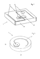
- FIG. 1 shows a perspective illustration of an embodiment of the transponder according to the invention
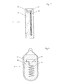
- FIG. 2 shows a perspective view of a further embodiment
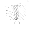
- FIG. 3 shows a third embodiment of the transponder according to the invention in a cross section
- FIGS. 4 and 5 show further embodiments in cross section.
- Fig. 1 is an example of a possible embodiment of a SAW transponder 1 with a substantially S-shaped dipole wire antenna 21 in the form of open Planarschleifen with axial dispersion, embedded in an electrically non-conductive, dielectric material 30 with application-specific shape and integrated devices for mechanical attachment 53 of the transponder 1, shown.
- the dielectric material 30 may be formed from ceramic molding compounds having a relative dielectric constant ⁇ r in the range of about 8 to 13.
- FIG. 2 shows a compact arrangement of a substantially disk-shaped SAW transponder 1.
- This embodiment is particularly suitable for applications with limited space or for, even submerged, integration in a metallic environment.
- a minimum distance between the antenna and the metallic environment is required to avoid interference by reflection of the radio waves or detuning of the antenna by changing the radiation resistance through the metallic surfaces.
- Due to the limited space available it is advantageous, in combination with the dielectric effect of the potting material 30 explained in more detail below, on the antenna characteristics to use a groundless monopole wire antenna 22, i. Do not connect or ground the second connector to an antenna, but leave it open.
- the geometric shape of the antenna 22 is here in turn adaptable to the application and, for example, as shown in Fig.
- antenna 23 also be an elongated antenna 23.
- antenna forms include, for example, closed wire loops ("loop antennas"), or helical antennas 24, as shown by way of example in Fig. 4.
- An additional advantage of wire antennas 21, 22, 23, 24 is the ability to connect and thereby spatially separate the signal-generating SAW element 10 and the transmit / receive antenna through an RF-capable connection, such as a coaxial cable 40, as in FIG Fig. 5 shown as an example.
- wire antennas 21, 22, 23, 24 Another advantage of using wire antennas 21, 22, 23, 24 is the ease of matching the radiation resistance of the antenna to the input impedance of the SAW element. In previously known systems, this mostly happens via own matching circuits. When using the embedded wire antennas according to the invention 21,22,23,24, this is not necessary in combination with suitable SAW elements.
- the adaptation can be made, within certain physical limits, via the choice of the antenna wire length. According to the same scheme, it is also possible to adapt the antenna (s) to different environmental conditions, eg different dielectrics.
- the dielectric properties of the embedding material 30 at the operating frequency is a crucial factor.
- the minimum antenna length results directly from the operating frequency.
- the effective antenna length increases as a function of the relative dielectric constant of the dielectric ⁇ r for the corresponding operating frequency. This makes it possible to reduce the constructive antenna length compared to non-embedded antennas by a factor of up to 1 / ⁇ r . Similarly, it is also possible to reduce the required minimum distance to metallic surfaces by the same factor.
- the choice of the embedding material 30 depends on the mechanical properties and dielectric properties of the processability and optionally the thermal and / or chemical resistance. With regard to the latter point, embedding in a suitable material 30 allows a gas and liquid-impermeable, hermetic sealing of the transponder components and thus reliable corrosion protection. For certain materials that are desired, for example, for reasons of chemical resistance and / or process requirements, such as sterilizability, as a shell material in which a direct embedding is not possible, a two-stage wrapper is advantageous.
- the electronic components of the SAW transponder 1 are first According to the invention embedded in a suitable material 30 and this unit then packed in a corresponding, eg chemoresistant, secondary sheath 33, for example, melted in glass or quartz, as exemplified in Fig. 4.
- An advantage of this procedure is that the transponder components are optimally protected and the shape of the primary embedding 30 of the SAW transponder 1 can be optimized in a simple manner for the enclosure with a, preferably simple and inexpensive, secondary envelope 33.
- the embedding in a dielectric may optionally be carried out by various methods, depending on the geometry, the choice of the material 30, the conditions of use and the quantities to be produced. Since in the majority of embedding increased temperatures of up to several 100 ° C occur, it is advantageous here to use high temperature resistant SAW elements that can permanently withstand temperatures> 400 ° C and temporarily temperatures> 600 ° C, according to the literature. At the same time, before embedding it is essential to install the actual SAW crystal (s) in a hermetically sealed housing to protect the surface of the signal generating element from direct contact with the embedding compound. Here come advantageously ceramic or metallic standard microelectronic housing for high frequency applications used.
- SAW transponders 1 particularly advantageous embedding are on the one hand injection molding process for embedding in polymeric materials, on the other hand (low temperature) sintering process, especially when embedded in ceramic or thermosetting compounds and pouring using chemical and / or thermal curing, organic polymeric or inorganic, for example silicate-glassy and / or ceramic molding compositions.
- the outside of the transponder 1 can be designed in accordance with the requirements of the applications, as shown by way of example in FIGS. 1 to 5, and also includes the possibility of integrating mechanical functionalities, such as a fastening thread 51 and / or seals 52, or also Provide mounting holes 53 through the transponder 1 itself and thus produce highly functional SAW transponder 1.
- the arrangement according to the invention also makes it possible to have fastening bores 53 or similar adaptations of the transponder to the application only by the end user, for example during assembly. Due to the complete embedding, all transponder components are fixed in their position and hermetically sealed so that a machining of the embedding material 30 does not cause an increased risk of damage, for example due to corrosion. As can be seen from FIG. 1, such breakthroughs 53, etc. can also be applied in the inner region of the transponder 1, as long as this does not injure transponder components.
- Suitable designs allow use of the inventive arrangement for the construction of SAW sensors, in particular for physical parameters. Temperature measurements are, assuming a suitable SAW element, in principle possible with all the structures shown, but limited by the heat capacity of the embedding material 30 in the temporal dynamics. To improve the dynamic response, for example, an installation of a townleitelements between the measuring point and the housing of the SAW sensor element 10 or an arrangement of the housing with the SAW sensor element 10 directly at the measuring point, as shown in Fig. 5, advantageous. Embedded contacts can be realized, for example, for wiring electro-technical SAW sensors. Likewise, it is possible to realize pressure / tension sensors or torque sensors.
- wire antennas 21, 22, 23, 24 as a transmission element for SAW transponders 1 in combination with an embedding of the transponder components in a dielectric material 30 represents a significant advance in terms of expanding the technical-industrial applicability of SAW-ID Marks and SAW sensors.
- the inventive arrangement it is possible to realize cost-effective, mechanically, thermally and / or chemically robust SAW transponder 1 with flexibly adaptable to specific requirements designs or sizes and / or electromagnetic transmission characteristics.
Abstract
Description
Die Erfindung betrifft einen Transponder für Identifikations- und/oder Sensoranwendungen bestehend aus mindestens einem signalerzeugenden Transponder-Element und wenigstens einer Antenne.The invention relates to a transponder for identification and / or sensor applications consisting of at least one signal-generating transponder element and at least one antenna.
Die Verwendung von akustischen Oberflächenwellen (surface acoustic wave, SAW) - Elementen als physikalische oder chemische Sensoren und/oder Identifikationsmarken (ID-Marken) ist seit geraumer Zeit bekannt und auch in kommerziellen Produkten umgesetzt. Besonders vorteilhaft an derartigen Systemen ist, dass sie kontaktfrei und passiv betrieben werden können, d.h. keine Energieversorgung, wie beispielsweise eine Batterie, im Bereich der ID-Marke bzw. des Sensors erforderlich ist. Für den kontaktfreien Betrieb ist nur eine Antenne erforderlich, die elektromagnetische Wellen eines Abfragesignals von einem Lesegerät empfängt und das von dem SAW-Element generierte Antwortsignal zurücksendet. Die Art und Form der Transponder, und damit verbunden dieser Antennen, ist von entscheidender Bedeutung für die Anwendbarkeit von passiven SAW-Transpondern.The use of surface acoustic wave (SAW) elements as physical or chemical sensors and / or identification marks (ID marks) has been known for quite some time and has also been implemented in commercial products. It is particularly advantageous with such systems that they can be operated contactlessly and passively, i. no power supply, such as a battery, is required near the ID tag or sensor. For non-contact operation, only one antenna is required which receives electromagnetic waves of an interrogation signal from a reader and returns the response signal generated by the SAW element. The type and shape of the transponders, and associated antennas, is crucial to the applicability of passive SAW transponders.
In kommerziell erhältlichen passiven SAW-Transpondern werden für die Signalübertragung in der Regel Planarantennen auf einem dielektrischen Trägermaterial verwendet. Das eigentliche, signalerzeugende SAW-Element ist dabei meist in einem Metall- oder Keramikgehäuse untergebracht, das auf der Trägerplatte der Planarantenne angeordnet ist. Für technische Anwendungen können derartige Anordnungen in abgedichteten, meist zwei- oder mehrteiligen Kunststoffgehäusen untergebracht werden, um das System mechanisch sowie vor Verschmutzung und/oder korrosiven Angriffen zu schützen. Ein alternativer Aufbau, wie er beispielsweise für die Temperaturüberwachung von Leiterseilen an Hochspannungsleitungen verwendet werden kann (Teminova et. al., Proc. Sensor 2005, Vol. II), basiert auf der Verwendung einer Schlitzantenne. Beiden Systemen ist gemein, dass die Antenne, für eine bestimmte Betriebsfrequenz und Leistung, in Form und Größe wenig flexibel ist und signifikant die Form und Größe des SAW-Transponders insgesamt beeinflusst. Zudem sind derartige Transponder vergleichsweise anfällig gegen Beschädigungen, z.B. mechanische Verformungen der Schlitzantenne oder Undichtheiten der Schutzgehäuse.In commercially available passive SAW transponders, planar antennas on a dielectric substrate are typically used for signal transmission. The actual, signal-generating SAW element is usually housed in a metal or ceramic housing, which is arranged on the support plate of the planar antenna. For technical applications such arrangements can be housed in sealed, usually two- or multi-part plastic housings to protect the system mechanically and against contamination and / or corrosive attacks. An alternative structure, such as can be used for temperature monitoring of conductors on power lines (Teminova et al., Proc. Sensor 2005, Vol. II), is based on the use of a slot antenna. Common to both systems is that, for a given operating frequency and power, the antenna is not very flexible in shape and size and significantly affects the overall shape and size of the SAW transponder. In addition, such transponder are relatively susceptible to damage, such as mechanical deformation of the slot antenna or leaks of the protective housing.
Eine weitere alternative Möglichkeit zum Bau einer Antenne für SAW-Sensoren ist aus
Für einen praktischen Einsatz einer ID-Marke oder eines Sensors sind in der Regel die Baugröße und -form zusammen mit entsprechenden mechanischen, thermischen und/oder chemischen Stabilitäten des Sensors bzw. der ID-Marke die entscheidenden technischen Kriterien, gefolgt vom Preis und somit dem Aufwand der Herstellung und des Einsatzes. Sensoren bzw. ID-Marken sollten mit möglichst geringem Aufwand und voller Funktionalität integrierbar sein, ohne die Funktionalität der zu überwachenden bzw. zu identifizierenden Geräte oder Objekte zu beeinträchtigen oder signifikante Änderungen an der Konstruktion bzw. dem Design notwendig zu machen. Dies macht möglichst kompakte, robuste SAW-Transponder wünschenswert. Besonders nützlich wäre es auch, SAW-Transponder bündig oder auch versenkt auch in metallische Objektoberflächen integrieren zu können, beispielsweise um sie vor Beschädigungen zu schützen und/oder unsichtbar zu machen. Letzteres ist insbesonders ein Kriterium wenn das Erscheinungsbild einer Produktoberfläche nicht verändert werden darf oder beispielsweise bei Verwendung als verdecktes Diebstahlschutz-System.For a practical use of an ID mark or a sensor, the size and shape together with the corresponding mechanical, thermal and / or chemical stabilities of the sensor or the ID mark are usually the decisive technical criteria, followed by the price and thus the Cost of production and use. Sensors or ID marks should be integrable with the least possible effort and functionality, without compromising the functionality of the devices or objects to be monitored or identified, or necessitating significant changes to the design or design. This makes compact, robust SAW transponders desirable. It would also be particularly useful to use SAW transponders flush or recessed to integrate into metallic object surfaces, for example, to protect them from damage and / or invisible. The latter is in particular a criterion if the appearance of a product surface may not be changed or, for example, when used as a hidden theft protection system.
Neben der Miniaturisierung ist es für einen praktischen Einsatz von beträchtlichem Vorteil, die Eigenschaften passiver SAW-Transducer möglichst flexibel an spezifische Anwendungserfordernisse anpassen zu können. Dies betrifft die Geometrie, die Einbaubarkeit inklusive der Möglichkeit zur flexiblen Positionierung von Befestigungselementen ebenso wie die Stabilität des Transponders insgesamt unter Betriebsbedingungen. Mit vorbekannten Systemen ist dies, ebenso wie die Miniaturisierung, nur eingeschränkt möglich; so ist beispielsweise bei Verwendung von Transpondern mit Kunststoffgehäuse die Anbringung zusätzlicher Bohrungen für die Befestigung nicht oder nur mit großem Aufwand für Redesign des Gehäuses und zusätzliche Dichtungselemente möglich. Bei Verwendung von SAW-Transpondern gemäß dem Stand der Technik ist es daher in der Regel notwendig, das zu überwachende Objekt an die Anforderungen des Transponders anzupassen, was einer verbreiteten praktischen Anwendung von SAW-Sensorsystemen bzw. SAW-ID-Marken oft entgegensteht.In addition to miniaturization, it is of considerable advantage for a practical use to be able to adapt the properties of passive SAW transducers as flexibly as possible to specific application requirements. This concerns the geometry, the installability including the possibility for flexible positioning of fasteners as well as the stability of the transponder overall under operating conditions. With previously known systems, this, as well as the miniaturization, is limited; For example, when using transponders with plastic housing, the attachment of additional holes for mounting not or only with great effort for redesign of the housing and additional sealing elements possible. When using SAW transponders according to the prior art, it is therefore generally necessary to adapt the object to be monitored to the requirements of the transponder, which often precludes widespread practical application of SAW sensor systems or SAW-ID marks.
Der Erfindung liegt die Aufgabe zu Grunde, Transponder zur Verfügung zu stellen, die kompakter, robuster und gleichzeitig flexibler einsetzbar sind als vorbekannte Systeme.The object of the invention is to provide transponders which are more compact, robust and at the same time more flexible than previously known systems.
Gelöst wird diese Aufgabe erfindungsgemäß mit einem Transponder, welcher die Merkmale des Anspruches 1 aufweist.This object is achieved according to the invention with a transponder, which has the features of
Bevorzugte und vorteilhafte Ausführungsformen sind Gegenstand der Unteransprüche.Preferred and advantageous embodiments are subject of the dependent claims.
Erfindungsgemäß wird zunächst vorgeschlagen, anstelle der üblicherweise in passiven SAW-Transpondern für die Signalübertragung verwendeten Antennentypen Drahtantennen zu verwenden. Die Übertragungscharakteristika von Drahtantennen können, beispielsweise durch Variation der Form, Ausrichtung und/oder Länge der Antenne, einfach und flexibel an spezifische Anforderungen einer Anwendung angepasst werden. Weiters stellen Drahtantennen, im Vergleich zu Planar- oder Schlitzantennen, eine äußerst kostengünstige technische Lösung dar. Problematisch bei der Verwendung von Drahtantennen ist, dass derartige Antennen, insbesonders in kompakten Bauformen, geringe mechanische Stabilitäten aufweisen. Eine, unter Umständen bereits geringfügige, Verformung der Antenne kann ausreichen um die Antennencharakteristik signifikant zu verändern und dadurch zu einer Funktionsstörung zu führen. Ein weiterer Punkt ist, dass die Möglichkeit zur Miniaturisierung von Antennen für eine gegebene Betriebsfrequenz durch physikalische Gesetzmäßigkeiten limitiert ist. Für eine Signaleinkopplung ist eine Antennen-Mindestlänge von λ/4 erforderlich, wobei λ (Lambda) die Vakuum-Wellenlänge der elektromagnetischen Strahlung für die jeweilige Betriebsfrequenz bezeichnet. Bei einer Betriebsfrequenz im freien ISM-S-Band (~ 2,45 GHz) entspricht das einer minimalen Antennenlänge von 31 mm.According to the invention, it is first proposed to use wire antennas instead of the types of antennas commonly used in passive SAW transponders for signal transmission. The transmission characteristics of wire antennas For example, by varying the shape, orientation and / or length of the antenna, it can be easily and flexibly adapted to specific requirements of an application. Furthermore, wire antennas, compared to planar or slot antennas, an extremely cost-effective technical solution. A problem with the use of wire antennas is that such antennas, especially in compact designs, have low mechanical stabilities. A, possibly even slight, deformation of the antenna may be sufficient to significantly change the antenna characteristics and thereby lead to a malfunction. Another issue is that the ability to miniaturize antennas for a given operating frequency is limited by physical laws. For signal coupling, a minimum antenna length of λ / 4 is required, where λ (lambda) denotes the vacuum wavelength of the electromagnetic radiation for the respective operating frequency. At an operating frequency in the free ISM-S band (~ 2.45 GHz) this corresponds to a minimum antenna length of 31 mm.
Um diese Probleme zu lösen und die vorteilhaften Eigenschaften von Drahtantennen in praktischen Transponderanwendungen nutzen zu können, wird vorgeschlagen, an mindestens ein signalerzeugendes SAW-Element in einem hermetisch dichten, HF (high frequency) - tauglichen Gehäuse eine oder mehrere Drahtantennen mit angepasster, für die Anwendung vorteilhafter Geometrie anzuschließen und diese Kombination vollständig in ein elektrisch nicht leitfähiges, dielektrisches Material, beispielsweise einen polymeren oder keramischen Werkstoff, einzubetten, welches die elektronischen Bauteile schützt und mechanisch stabilisiert und gleichzeitig die effektiv erforderliche konstruktive Antennenlänge reduziert.In order to solve these problems and to be able to use the advantageous properties of wire antennas in practical transponder applications, it is proposed to provide one or more wire antennas with adapted, for at least one signal-generating SAW element in a hermetically sealed, HF (high frequency) -tuitable housing Apply application advantageous geometry and completely embed this combination in an electrically non-conductive dielectric material, such as a polymeric or ceramic material, which protects the electronic components and mechanically stabilized while reducing the effectively required constructive antenna length.
Die Einbettung aller Transponderkomponenten in ein dielektrisches Material erfüllt mehrere, für die Funktion sowie die Miniaturisierbarkeit eines SAW-Transponders wichtige Funktionen. Durch die Einbettung werden die Transponder-Bauteile, insbesonders die Antennen, auch bei starken mechanischen und/oder thermischen Belastungen, wie beispielsweise Stößen oder raschen Heiz/Kühl-Zyklen, an ihren festgelegten Positionen bzw. in ihren vorgegebenen Formen gehalten, wodurch gleich bleibende Antenneneigenschaften gewährleistet werden können. Gleichzeitig stellt die Einbettung insgesamt einen effektiven Schutz des Transponders vor mechanischen oder sonstigen physikalischen Belastungen dar und erlaubt eine Anwendung unter entsprechenden Bedingungen. Der zweite essentielle Punkt ist die Ausnützung der dielektrischen Eigenschaften des Einbettungsmaterials um die erforderlichen konstruktiven Antennenlängen zu reduzieren. Dies ermöglicht eine signifikante Reduktion der erforderlichen Baugröße und erlaubt dadurch beispielsweise den Bau von kompakten und auch in metallische Bauteile integrierbaren passiven SAW-Transpondern. Als dritten Punkt schützt die Einbettung in eine chemisch inerte, hermetisch dichte Umhüllung die Transponderkomponenten vor korrosiven Angriffen und erlaubt somit eine Anwendung auch unter chemisch rauen Bedingungen.The embedding of all transponder components in a dielectric material fulfills several important functions for the function as well as the miniaturization of a SAW transponder. By embedding the transponder components, especially the antennas, even at high mechanical and / or thermal loads, such as bumps or rapid heating / cooling cycles, held in their predetermined positions or in their predetermined forms, creating a constant Antenna properties can be guaranteed. At the same time, the overall embedding provides an effective protection of the transponder from mechanical or other physical stresses and allows use under appropriate conditions. The second essential point is to exploit the dielectric properties of the encapsulant material to reduce the required design antenna lengths. This allows a significant reduction of the required size and thereby allows, for example, the construction of compact and also integrable in metallic components passive SAW transponders. As a third point, the embedding in a chemically inert, hermetically sealed enclosure protects the transponder components from corrosive attacks and thus allows application even under chemically harsh conditions.
Weitere Einzelheiten, Merkmale und Vorteile des erfindungsgemäßen Transponders ergeben sich aus der nachstehenden Beschreibung unter Bezugnahme auf die angeschlossenen Zeichnungen, in welchen bevorzugte Ausführungsformen dargestellt sind. Es zeigt Fig. 1 eine perspektivische Darstellung einer Ausführungsform des erfindungsgemäßen Transponders, Fig. 2 eine perspektivische Darstellung einer weiteren Ausführungsform, Fig. 3 eine dritte Ausführungsform des erfindungsgemäßen Transponders in einem Querschnitt, und Fig. 4 und 5 weitere Ausführungsformen im Querschnitt.Further details, features and advantages of the transponder according to the invention will become apparent from the following description with reference to the accompanying drawings, in which preferred embodiments are shown. 1 shows a perspective illustration of an embodiment of the transponder according to the invention, FIG. 2 shows a perspective view of a further embodiment, FIG. 3 shows a third embodiment of the transponder according to the invention in a cross section, and FIGS. 4 and 5 show further embodiments in cross section.
Der primäre Vorteil der Verwendung von Drahtantennen 21,22,23,24 ist, dass Form und Anordnung in einem SAW-Transponder 1 äußerst flexibel an die jeweilige Anwendung, insbesonders das Platzangebot und die gewünschte Abstrahlcharakteristik, angepasst werden können. In Fig. 1 ist exemplarisch eine mögliche Ausführung eines SAW-Transponders 1 mit einer im Wesentlichen S-förmigen Dipol-Drahtantenne 21 in Form offener Planarschleifen mit axialem Abstrahlverhalten, eingebettet in ein elektrisch nicht leitfähiges, dielektrisches Material 30 mit anwendungsspezifischer Form und integrierten Vorrichtungen zur mechanischen Befestigung 53 des Transponders 1, dargestellt. Das dielektrische Material 30 kann aus keramischen Formmassen gebildet sein, welche eine relative Dielektrizitätskonstante εr im Bereich von ca. 8 bis 13 aufweisen. Besonders vorteilhaft ist der Einsatz von keramischen Formmassen auf A1203-Basis mit einer Dielektrizitätskonstante εr im Bereich von 9 bis 10. Durch die erfindungsgemäße Einbettung in die Keramik lassen sich die Abmessungen des SAW-Transducers im Vergleich einer Anordnung an der Umgebungsluft (εr = 1) um ca. 2/3 verringern.The primary advantage of using
In Fig. 2 ist eine Kompakt-Anordnung eines im Wesentlichen scheibenförmigen SAW-Transponders 1 dargestellt. Diese Ausführungsform ist für Anwendungen mit beschränktem Platzangebot bzw. für eine, auch versenkte, Integration in eine metallische Umgebung besonders geeignet. Bei Einbau in ein metallisches Bauteil ist ein Mindestabstand zwischen Antenne und der metallischen Umgebung erforderlich, um eine Störung durch Reflektion der Funkwellen bzw. eine Verstimmung der Antenne durch Veränderung des Abstrahl-Widerstands durch die metallischen Flächen zu vermeiden. Durch das limitierte Platzangebot ist es hier, in Kombination mit der in Folge näher erläuterten dielektrischen Wirkung des Einbettungsmaterials 30 auf die Antennencharakteristika, vorteilhaft, eine massefreie Monopol-Drahtantenne 22 zu verwenden, d.h. den zweiten Anschluss nicht mit einer Antenne zu verbinden oder auf Masse zu legen, sondern offen zu lassen. Die geometrische Form der Antenne 22 ist hier wiederum an die Anwendung anpassbar und kann beispielsweise, wie in Fig. 3 dargestellt, auch eine gestreckte Antenne 23 sein. Weitere denkmögliche, mit Drahtantennen einfach realisierbare und für bestimmte Anwendungen vorteilhafte Antennenformen umfassen beispielsweise geschlossene Drahtschleifen ("Loopantennen"), oder Helixantennen 24, wie beispielhaft in Fig. 4 dargestellt. Einen zusätzlichen Vorteil von Drahtantennen 21,22,23,24 stellt die Möglichkeit dar, das signalerzeugende SAW-Element 10 und die Sende/Empfangsantenne durch eine HF-taugliche Verbindung, beispielsweise ein Koaxialkabel 40, zu verbinden und dadurch räumlich zu separieren, wie in Fig. 5 exemplarisch dargestellt.FIG. 2 shows a compact arrangement of a substantially disk-
Ein weiterer Vorteil der Verwendung von Drahtantennen 21,22,23,24 ist die einfache Anpassung des Abstrahlwiderstands der Antenne an die Eingangsimpedanz des SAW-Elements. In vorbekannten Systemen geschieht dies zumeist über eigene Anpass-Schaltungen. Bei Verwendung der erfindungsgemäßen eingebetteten Drahtantennen 21,22,23,24 ist dies, in Kombination mit geeigneten SAW-Elementen, nicht erforderlich. Die Anpassung kann, innerhalb gewisser physikalischer Grenzen, über die Wahl der Antennendrahtlänge erfolgen. Nach dem selben Schema ist es auch möglich, die Antenne(n) an unterschiedliche Umgebungsbedingungen, z.B. unterschiedliche Dielektrika, anzupassen.Another advantage of using
Für den Aufbau kompakter, funkabfragbarer SAW-Transponder 1 sind die dielektrischen Eigenschaften des Einbettungsmaterials 30 bei der Betriebsfrequenz ein entscheidender Faktor. Bei nicht eingebetteten Antennen ergibt sich die minimale Antennenlänge unmittelbar aus der Betriebsfrequenz. Bei einer Einbettung in ein Dielektrikum erhöht sich die effektive Antennenlänge in Abhängigkeit der relativen Dielektrizitätskonstante des Dielektrikums εr für die entsprechende Betriebsfrequenz. Dadurch ist es möglich, die konstruktive Antennenlänge im Vergleich zu nicht eingebetteten Antennen um einen Faktor von bis zu 1/√εr, zu verringern. Analog ist es auch möglich, den erforderlichen Mindestabstand zu metallischen Flächen um den selben Faktor zu verringern. In Summe ist es, anders als mit vorbekannten Systemen, somit möglich, kompakte passive SAW-Transponder 1 mit lateralen Abmaßen < 30 mm für Betriebsfrequenzen im Bereich des freien ISM-S-Bandes zu bauen und derartige passive Transponder 1 auch in unmittelbarer Nähe von bzw. eingebaut in Oberflächen metallischer Objekte zu betreiben.For the construction of compact,
Die Auswahl des Einbettungsmaterials 30 hängt neben den mechanischen und dielektrischen Eigenschaften von der Verarbeitbarkeit und gegebenenfalls der thermischen und/oder chemischen Beständigkeit ab. Bezüglich letzterem Punkt ermöglicht die Einbettung in einen geeigneten Werkstoff 30 eine gas- und flüssigkeitsundurchlässige, hermetische Abdichtung der Transponderkomponenten und somit einen zuverlässigen Korrosionsschutz. Für bestimmte Materialien, die beispielsweise aus Gründen der chemischen Beständigkeit und/oder von Prozessanforderungen, wie Sterilisierbarkeit, als Hüllenmaterial gewünscht sind, bei denen eine direkte Einbettung aber nicht möglich ist, ist eine zweistufige Einhüllung vorteilhaft. Die elektronischen Komponenten des SAW-Transponders 1 werden zunächst erfindungsgemäß in ein geeignetes Material 30 eingebettet und diese Einheit dann in eine entsprechende, z.B. chemoresistente, Sekundärhülle 33 verpackt, beispielsweise in Glas bzw. Quarz eingeschmolzen, wie beispielhaft in Fig. 4 dargestellt. Vorteilhaft an dieser Vorgangsweise ist, dass die Transponderkomponenten optimal geschützt sind und die Form der Primäreinbettung 30 des SAW-Transponders 1 in in einfacher Weise für die Umhüllung mit einer, vorzugsweise einfachen und kostengünstigen, Sekundärhülle 33 optimiert werden kann.The choice of the embedding
Die Einbettung in ein Dielektrikum kann wahlweise, abhängig von der Geometrie, der Wahl des Materials 30, den Einsatzbedingungen und den zu produzierenden Stückzahlen, mittels verschiedener Verfahren durchgeführt werden. Da bei der Mehrzahl der Einbettverfahren erhöhte Temperaturen von bis zu einigen 100 °C auftreten, ist es hier vorteilhaft, Hochtemperaturbeständige SAW-Elemente zu verwenden, die literaturgemäß dauerhaft Temperaturen > 400 °C und kurzzeitig Temperaturen > 600 °C standhalten können. Gleichzeitig ist es vor dem Einbetten unabdingbar, den bzw. die eigentlichen SAW-Kristall(e) in ein hermetisch dichtes Gehäuse einzubauen um die Oberfläche des signalerzeugenden Elements vor direktem Kontakt mit der Einbettungsmasse zu schützen. Hier kommen vorteilhafterweise keramische oder metallische Standard-Mikroelektronikgehäuse für Hochfrequenzanwendungen zum Einsatz. Für die Produktion von SAW-Transpondern 1 besonders vorteilhafte Einbettungsverfahren sind einerseits Spritzguss-Verfahren für die Einbettung in polymere Werkstoffe, andererseits (Niedertemperatur-) Sinterpressverfahren, insbesonders bei Einbettung in keramische oder duromere Formmassen sowie Eingießverfahren unter Verwendung chemisch und/oder thermisch härtender, organisch-polymerer oder anorganischer, beispielsweise silikatisch-glasartiger und/oder keramischer Formmassen. Bei Verwendung polymerer Formmassen kann es anwendungsabhängig vorteilhaft sein, faserverstärkte, besonders vorzugsweise Glasfaserverstärkte, oder sonstig, vorzugsweise mineralisch, gefüllte Materialien zu verwenden, um dadurch beispielsweise mechanische und thermische Festigkeiten zu verbessern und gleichzeitig die, bei organischen Werkstoffen vergleichsweise niedrigeren, relativen Dielektrizitätskonstanten zu erhöhen. Insbesonders beim Vergießen ist es zudem wahlweise möglich, die Bauteile in einem Block einzugießen oder die Transponderkomponenten in einen geeigneten Trägerbauteil 31 einzubauen und die verbleibenden Hohlräume mit einer, vorzugsweise niederviskosen, Vergussmasse auszugießen, wie beispielhaft in Fig. 4 dargestellt.The embedding in a dielectric may optionally be carried out by various methods, depending on the geometry, the choice of the
Die Außenseite des Transponders 1 kann entsprechend den Anforderungen der Anwendungen gestaltet werden, wie in Fig. 1 - Fig. 5 exemplarisch dargestellt und umfasst auch die Möglichkeit, mechanische Funktionalitäten, wie beispielsweise ein Befestigungsgewinde 51 und/oder Dichtungen 52, zu integrieren, oder auch Befestigungsöffnungen 53 durch den Transponder 1 selbst vorzusehen und somit hochfunktionelle SAW-Transponder 1 zu produzieren. Insbesonders bei Verwendung von polymeren Einbettungsmassen 30 ermöglicht die erfindungsgemäße Anordnung auch, Befestigungsbohrungen 53 oder ähnliche Anpassungen des Transponders an die Anwendung erst durch den Endnutzer, beispielsweise bei der Montage, vornehmen zu lassen. Durch die vollständige Einbettung sind dabei alle Transponderkomponenten in ihrer Lage fixiert und hermetisch dicht abgeschirmt, sodass eine spanende Bearbeitung des Einbettungsmaterials 30 kein erhöhtes Beschädigungsrisiko, beispielsweise durch Korrosion, bewirkt. Wie aus Fig. 1 ersichtlich, können derartige Durchbrüche 53, etc. auch im inneren Bereich des Transponders 1 angebracht werden, solange dadurch nicht Transponderkomponenten verletzt werden.The outside of the
Geeignete Bauformen erlauben eine Verwendung der erfindungsgemäßen Anordnung zum Bau von SAW-Sensoren, insbesonders für physikalische Parameter. Temperaturmessungen sind, ein geeignetes SAW-Element vorausgesetzt, prinzipiell mit allen dargestellten Aufbauten möglich, durch die Wärmekapazität des Einbettungsmaterials 30 aber in der zeitlichen Dynamik begrenzt. Zur Verbesserung des dynamischen Ansprechverhaltens ist beispielsweise ein Einbau eines Wärmeleitelements zwischen dem Messpunkt und dem Gehäuse des SAW-Sensorelements 10 oder eine Anordnung des Gehäuses mit dem SAW-Sensorelement 10 unmittelbar am Messpunkt, wie in Fig. 5 demonstriert, vorteilhaft. Für die Beschaltung elektrotechnischer SAW-Sensoren können beispielsweise eingebettete Kontakte realisiert werden. Gleichfalls ist es möglich, Druck/Zugsensoren bzw. Drehmomentsensoren zu realisieren.Suitable designs allow use of the inventive arrangement for the construction of SAW sensors, in particular for physical parameters. Temperature measurements are, assuming a suitable SAW element, in principle possible with all the structures shown, but limited by the heat capacity of the embedding
Die erfindungsgemäß vorgeschlagene Verwendung von Drahtantennen 21,22,23,24 als Übertragungselement für SAW-Transponder 1 in Kombination mit einer Einbettung der Transponderkomponenten in ein dielektrisches Material 30 stellt einen signifikanten Fortschritt in Hinblick auf die Erweiterung der technisch-industriellen Anwendbarkeit von SAW-ID-Marken und SAW-Sensoren dar. Durch die erfindungsgemäße Anordnung ist es möglich, kostengünstige, mechanisch, thermisch und/oder chemisch robuste SAW-Transponder 1 mit flexibel an spezifische Anforderungen anpassbaren Bauformen bzw. -größen und/oder elektromagnetischen Übertragungscharakteristika zu realisieren. Ebenso ist es durch die erfindungsgemäße Anordnung erstmals möglich, kompakte SAW-Transponder 1 für das ISM-S-Band zu bauen, die in die Oberflächen metallischer Bauteile ohne Beeinträchtigung der Funktionalitäten der SAW-ID-Marke bzw. des SAW-Sensors integriert werden können.The use according to the invention of
Claims (17)
Applications Claiming Priority (1)
| Application Number | Priority Date | Filing Date | Title |
|---|---|---|---|
| AT13522005A AT502231A1 (en) | 2005-08-11 | 2005-08-11 | Transponders |
Publications (1)
| Publication Number | Publication Date |
|---|---|
| EP1752916A1 true EP1752916A1 (en) | 2007-02-14 |
Family
ID=37232873
Family Applications (1)
| Application Number | Title | Priority Date | Filing Date |
|---|---|---|---|
| EP06450101A Withdrawn EP1752916A1 (en) | 2005-08-11 | 2006-07-17 | SAW transponder having a wire antenna |
Country Status (2)
| Country | Link |
|---|---|
| EP (1) | EP1752916A1 (en) |
| AT (1) | AT502231A1 (en) |
Cited By (3)
| Publication number | Priority date | Publication date | Assignee | Title |
|---|---|---|---|---|
| DE102015122553A1 (en) | 2015-12-22 | 2017-06-22 | Endress+Hauser Flowtec Ag | Converter device and by means of such a transducer device formed measuring system |
| DE102016113985A1 (en) * | 2016-07-28 | 2018-02-01 | Robert Bürkle GmbH | Press for laminating layer stacks to plate-shaped workpieces and measuring plate for such a press |
| WO2022101215A1 (en) * | 2020-11-16 | 2022-05-19 | Tdk Electronics Ag | Acoustic transponder, use of an acoustic transponder, method for producing a transponder, and acoustic transmission system |
Citations (3)
| Publication number | Priority date | Publication date | Assignee | Title |
|---|---|---|---|---|
| US4210900A (en) * | 1978-08-16 | 1980-07-01 | Honeywell Inc. | Surface acoustic wave code reader |
| US4746830A (en) * | 1986-03-14 | 1988-05-24 | Holland William R | Electronic surveillance and identification |
| DE10054198A1 (en) * | 2000-03-10 | 2001-09-13 | Siemens Ag | Torque acoustic surface wave (SAW) measurement method especially for torque acting on shaft driven by electric motor |
-
2005
- 2005-08-11 AT AT13522005A patent/AT502231A1/en not_active Application Discontinuation
-
2006
- 2006-07-17 EP EP06450101A patent/EP1752916A1/en not_active Withdrawn
Patent Citations (3)
| Publication number | Priority date | Publication date | Assignee | Title |
|---|---|---|---|---|
| US4210900A (en) * | 1978-08-16 | 1980-07-01 | Honeywell Inc. | Surface acoustic wave code reader |
| US4746830A (en) * | 1986-03-14 | 1988-05-24 | Holland William R | Electronic surveillance and identification |
| DE10054198A1 (en) * | 2000-03-10 | 2001-09-13 | Siemens Ag | Torque acoustic surface wave (SAW) measurement method especially for torque acting on shaft driven by electric motor |
Non-Patent Citations (1)
| Title |
|---|
| FINKENZELLER K: "RFID-Handbuch , PASSAGE", RFID HANDBOOK: GRUNDLAGEN UND PRAKTISCHE ANWENDUNGEN, XX, XX, 1998, pages 14 - 20, XP002257744 * |
Cited By (7)
| Publication number | Priority date | Publication date | Assignee | Title |
|---|---|---|---|---|
| DE102015122553A1 (en) | 2015-12-22 | 2017-06-22 | Endress+Hauser Flowtec Ag | Converter device and by means of such a transducer device formed measuring system |
| WO2017108278A1 (en) | 2015-12-22 | 2017-06-29 | Endress+Hauser Flowtec Ag | Converter device and measuring system produced with such a converter device |
| US11326913B2 (en) | 2015-12-22 | 2022-05-10 | Endress + Hauser Flowtec Ag | Transducer apparatus as well as measuring system formed by means of such a transducer apparatus |
| EP3998463A1 (en) | 2015-12-22 | 2022-05-18 | Endress + Hauser Flowtec AG | Transducer device and measuring system formed by such a transducer device |
| DE102016113985A1 (en) * | 2016-07-28 | 2018-02-01 | Robert Bürkle GmbH | Press for laminating layer stacks to plate-shaped workpieces and measuring plate for such a press |
| WO2022101215A1 (en) * | 2020-11-16 | 2022-05-19 | Tdk Electronics Ag | Acoustic transponder, use of an acoustic transponder, method for producing a transponder, and acoustic transmission system |
| EP4318423A3 (en) * | 2020-11-16 | 2024-03-13 | TDK Electronics AG | Acoustic transponder, use of an acoustic transponder, method for producing a transponder and acoustic transmission system |
Also Published As
| Publication number | Publication date |
|---|---|
| AT502231A1 (en) | 2007-02-15 |
Similar Documents
| Publication | Publication Date | Title |
|---|---|---|
| EP1752792B1 (en) | Distance measurement device using a Microwave-Antenna | |
| EP2656435B1 (en) | Tunable high-frequency filter | |
| EP3231035B1 (en) | Device for transferring signals from a metal housing | |
| DE102007061305A1 (en) | Multipart antenna with circular polarization | |
| EP1872309B1 (en) | Measuring sensor with at least one saw (surface acoustic wave) element | |
| EP1943614A1 (en) | Transponder | |
| EP2013939B1 (en) | Tuning element and tunable resonator | |
| DE102016120665B3 (en) | Radar sensor unit for use in harsh environments | |
| WO2009010724A1 (en) | Antennas | |
| WO2001009582A1 (en) | Device for measuring the contact pressure of a winding press element in an output transformer | |
| CA2886911A1 (en) | Tunable high-frequency filter | |
| EP1752916A1 (en) | SAW transponder having a wire antenna | |
| EP1752791B1 (en) | Distance measurement system using a microwave antenna and method for its fabrication | |
| CN111384537A (en) | Cavity filter and radio frequency communication equipment | |
| US5039966A (en) | Temperature-compensated tuning screw for cavity filters | |
| US20060176131A1 (en) | RF-resonator tuning | |
| EP2920839B1 (en) | Radio frequency filter with frequency stabilisation | |
| US20080055186A1 (en) | Enclosures with integrated antennas that make use of the skin effect | |
| DE102008001102A1 (en) | Pressure measuring device and method of manufacturing a pressure measuring device | |
| DE102018114889B4 (en) | Field device for process automation with a metal housing and a radio module with an antenna | |
| WO2015096958A2 (en) | Antenna-based proximity sensor | |
| US20200028230A1 (en) | Tunable Probe for High-Performance Cross-Coupled RF Filters | |
| EP3791441A1 (en) | Electronic unit having a housing and an antenna assembly | |
| EP2016292A1 (en) | Microwave position measurement apparatus and position measurement method | |
| EP3948819B1 (en) | Device for transferring signals from an at least partially metal housing designed for use in an explosion-prone region |
Legal Events
| Date | Code | Title | Description |
|---|---|---|---|
| PUAI | Public reference made under article 153(3) epc to a published international application that has entered the european phase |
Free format text: ORIGINAL CODE: 0009012 |
|
| AK | Designated contracting states |
Kind code of ref document: A1 Designated state(s): AT BE BG CH CY CZ DE DK EE ES FI FR GB GR HU IE IS IT LI LT LU LV MC NL PL PT RO SE SI SK TR |
|
| AX | Request for extension of the european patent |
Extension state: AL BA HR MK YU |
|
| AKX | Designation fees paid | ||
| REG | Reference to a national code |
Ref country code: DE Ref legal event code: 8566 |
|
| STAA | Information on the status of an ep patent application or granted ep patent |
Free format text: STATUS: THE APPLICATION IS DEEMED TO BE WITHDRAWN |
|
| 18D | Application deemed to be withdrawn |
Effective date: 20070815 |