EP1752841A1 - Elektronische Uhr, die durch ein Signal eines Beschleunigungsmessers in einem Bereitschaftsmodus eingestellt wird - Google Patents
Elektronische Uhr, die durch ein Signal eines Beschleunigungsmessers in einem Bereitschaftsmodus eingestellt wird Download PDFInfo
- Publication number
- EP1752841A1 EP1752841A1 EP05107278A EP05107278A EP1752841A1 EP 1752841 A1 EP1752841 A1 EP 1752841A1 EP 05107278 A EP05107278 A EP 05107278A EP 05107278 A EP05107278 A EP 05107278A EP 1752841 A1 EP1752841 A1 EP 1752841A1
- Authority
- EP
- European Patent Office
- Prior art keywords
- watch
- accelerometer
- mode
- display means
- electronic circuit
- Prior art date
- Legal status (The legal status is an assumption and is not a legal conclusion. Google has not performed a legal analysis and makes no representation as to the accuracy of the status listed.)
- Withdrawn
Links
Images
Classifications
-
- G—PHYSICS
- G04—HOROLOGY
- G04C—ELECTROMECHANICAL CLOCKS OR WATCHES
- G04C10/00—Arrangements of electric power supplies in time pieces
-
- G—PHYSICS
- G04—HOROLOGY
- G04G—ELECTRONIC TIME-PIECES
- G04G19/00—Electric power supply circuits specially adapted for use in electronic time-pieces
- G04G19/12—Arrangements for reducing power consumption during storage
Definitions
- the present invention relates to an electronic watch having a sleep mode.
- the electronic watch according to the present invention is of the type comprising a housing containing an electronic control circuit and display means supplied with electrical energy by an accumulator or a battery, the watch comprising an active mode of operation, in which the electronic circuit controls the display of the current time by the display means, and a standby operating mode, in which the electronic circuit controls the stopping of the display means, the electronic circuit triggering the passage of a mode of operation to another depending on the signal produced by a sensor.
- a watch of this type is described for example in the document EP 0 657 793 A a radio-controlled electronic watch having means for receiving a radio signal, a photoelectric sensor, and a liquid crystal display screen.
- a standby mode for minimizing the consumption of electrical energy and consisting in stopping the receiving means and turning off the display screen .
- the watch changes from standby mode to active mode when a watch pushbutton is pressed or when the sensor detects light.
- the watch changes from active mode to standby mode when no pusher pressure has been detected for ten days or when no light has been detected by the sensor for ten days.
- the system for triggering the standby mode and the active mode according to this document is not completely satisfactory because it mainly takes into account the lighting environment surrounding the watch. However, the watch can be placed in a place exposed to light without being used so far. This is why this watch must take into account, in addition to the signal provided by the sensor, an additional parameter constituted by the pressure on a pusher.
- the trigger system according to this document is therefore mainly adapted to a long-term storage of the watch.
- the present invention aims to overcome these disadvantages by providing a watch with a simpler and more effective trigger system.
- the invention proposes a watch of the type described above, characterized in that the sensor is constituted by an accelerometer which is arranged inside the housing and which comprises at least one axis of measurement of the acceleration experienced by the watch, so that the electronic circuit can determine if the watch is worn, to switch to active mode.
- the electronic circuit according to the invention has the advantage of actually taking into account the fact that the watch is worn by the user or not to trigger the transition from one mode of operation to another, which allows him to maximize savings. of electrical energy.
- the electronic circuit according to the invention is particularly responsive which allows it to go into standby mode as soon as the watch is no longer worn.
- the electronic circuit according to the invention requires a single detection means to trigger the transition from one mode of operation to another.
- the accelerometer makes it possible to detect the use of the watch before the user presses a pusher, by measuring the acceleration applied to the watch by the user when he grasps it.
- the accelerometer comprises several axes for measuring the acceleration so as to detect any acceleration experienced by the watch, including when this acceleration does not have a component along one of the axes.
- the accelerometer is constituted by a microstructure produced by micromachining in a plate of crystalline material, which facilitates its integration into the electronic circuit.
- the electronic control circuit comprises an integrated circuit board
- the accelerometer can be mounted directly on the wafer, along with the other components.
- the cost of this type of accelerometer is particularly interesting.
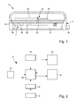
- an electronic watch 10 made according to the teachings of the invention. It comprises a housing 12 containing an electronic control circuit 14 and display means 16 supplied with electrical energy by an accumulator or a battery 18.
- the display means 16 are of the analog type and consist of at least two needles 20, 22 driven in rotation by an electric motor 24.
- the display means 16 may be of the digital type and include a liquid crystal screen.
- the electronic circuit 14 is here arranged on an integrated circuit board 25 fixed in the housing 12 and it comprises a microcontroller 26 which controls the display means 16 so as to display the current time according to a given time base. by a time division circuit 28 comprising a resonator.
- the watch 10 comprises an active operating mode, in which the electronic circuit 14 controls the display of the current time by the display means 16, and a standby operating mode, in which the electronic circuit 14 controls the stop display means 16.
- the electronic circuit 14 triggers the passage from one operating mode to another depending on the signal produced by a sensor 30.
- the senor 30 is constituted by an accelerometer 30 which is arranged inside the housing 12 and which comprises at least one measurement axis of the acceleration experienced by the watch 10, so that the electronic circuit 14 can determine if the watch 10 is worn, to go into active mode.
- the accelerometer 30 produces analog electrical signals representative of the instantaneous acceleration experienced by the watch 10. These signals pass through an analog-digital converter 32 before being input to the microcontroller 26, in the form of a digital signal .
- the accelerometer 30 may comprise several axes for measuring the acceleration, for example along two orthogonal axes, so as to detect any acceleration experienced by the watch 10, including when this acceleration does not have a component along one of the axes.
- the accelerometer 30 is constituted by a microstructure produced by micromachining in a plate of crystalline material such as silicon.
- the accelerometer 30 is therefore in the form of a microcircuit which is mounted directly on the wafer 25 with integrated circuits.
- the accelerometer 30 is of conventional type and the skilled person will not encounter any particular difficulty to choose one that is suitable for the implementation of the present invention.
- the watch 10 comprises a control member 34 such as a push button that can manually trigger the switch from one operating mode to another.
- This control member 34 may be constituted by a button used for setting the time of the watch 10 or by a button used to access the various functions of the watch 10.
- the microcontroller 26 can control the watch 10 in active mode.
- the operation of the watch 10 according to the invention is as follows.
- the watch 10 When the watch 10 is worn by a user, for example on the wrist in the case of a wristwatch, it undergoes accelerations of varying intensities due to natural movements made by the user. These accelerations are measured by the accelerometer 30 and transmitted to the microcontroller 26 which deduces that the watch 10 is worn. The watch 10 is then kept in its active mode and the hands 20, 22 are rotated to display the time.
- the watch 10 When the user leaves the watch 10, and the pose for example on a table, the watch 10 is stationary so that no acceleration can be measured by the accelerometer 30.
- the microcontroller 26 deduces while the watch 10 n is more worn and it triggers the transition to standby mode so as to minimize the consumption of the watch 10 in electrical energy.
- the autonomy of the watch 10 according to the invention is greater with equal battery capacity 18.
- the electronic circuit 14 controls the watch 10 in standby mode when the accelerometer 30 has not measured any acceleration for a determined duration, and / or when the measured acceleration values are below a threshold value, which allows to avoid a switch to untimely standby mode, for example when the wearer of the watch 10 is motionless for a few moments.
- the microcontroller 26 cuts off the power supply of the display means 16 with electrical energy, which causes the rotation of the hands to stop. 20, 22. However, the time continues to be counted down to allow the watch 10 to keep in memory the current time.
- the electronic circuit 14 comprises means 36 for storing the angular position occupied by the needles 20, 22 at the time of their stop.
- the microcontroller 26 is able to control the rotation of the needles 20, 22 from their stop position to their angular position corresponding to the current time.
- the microcontroller 26 deduces that the watch 10 is used again so that it triggers the transition to active mode.
Landscapes
- Engineering & Computer Science (AREA)
- Power Engineering (AREA)
- Physics & Mathematics (AREA)
- General Physics & Mathematics (AREA)
- Electric Clocks (AREA)
Priority Applications (1)
| Application Number | Priority Date | Filing Date | Title |
|---|---|---|---|
| EP05107278A EP1752841A1 (de) | 2005-08-08 | 2005-08-08 | Elektronische Uhr, die durch ein Signal eines Beschleunigungsmessers in einem Bereitschaftsmodus eingestellt wird |
Applications Claiming Priority (1)
| Application Number | Priority Date | Filing Date | Title |
|---|---|---|---|
| EP05107278A EP1752841A1 (de) | 2005-08-08 | 2005-08-08 | Elektronische Uhr, die durch ein Signal eines Beschleunigungsmessers in einem Bereitschaftsmodus eingestellt wird |
Publications (1)
| Publication Number | Publication Date |
|---|---|
| EP1752841A1 true EP1752841A1 (de) | 2007-02-14 |
Family
ID=35911100
Family Applications (1)
| Application Number | Title | Priority Date | Filing Date |
|---|---|---|---|
| EP05107278A Withdrawn EP1752841A1 (de) | 2005-08-08 | 2005-08-08 | Elektronische Uhr, die durch ein Signal eines Beschleunigungsmessers in einem Bereitschaftsmodus eingestellt wird |
Country Status (1)
| Country | Link |
|---|---|
| EP (1) | EP1752841A1 (de) |
Cited By (6)
| Publication number | Priority date | Publication date | Assignee | Title |
|---|---|---|---|---|
| WO2010027262A1 (en) * | 2008-09-03 | 2010-03-11 | Nederlandse Organisatie Voor Toegepast-Natuurwetenschappelijk Onderzoek Tno | Watch provided with locking mechanism |
| EP2180384A1 (de) * | 2008-10-22 | 2010-04-28 | Nederlandse Organisatie voor toegepast-natuurwetenschappelijk Onderzoek TNO | Uhr mit Sperrmitteln |
| FR2978567A1 (fr) * | 2011-07-29 | 2013-02-01 | Time2Ego | Procede de gestion d'une operation de sortie de veille d'une montre a affichage numerique |
| EP2687921A1 (de) * | 2012-07-18 | 2014-01-22 | ETA SA Manufacture Horlogère Suisse | Verbessertes Steuerungsverfahren eines elektronischen Geräts |
| WO2014120832A1 (en) * | 2013-01-31 | 2014-08-07 | Salutron, Inc. | Ultra-low power actigraphy based on dynamic threshold |
| JP2015175764A (ja) * | 2014-03-17 | 2015-10-05 | シチズンホールディングス株式会社 | 電子時計 |
Citations (4)
| Publication number | Priority date | Publication date | Assignee | Title |
|---|---|---|---|---|
| EP0657793A1 (de) | 1993-12-10 | 1995-06-14 | Seiko Instruments Inc. | Elektronische Uhr mit Zeitkorrektur über Funk |
| EP0952500A1 (de) * | 1997-11-20 | 1999-10-27 | Seiko Epson Corporation | Elektronische vorrichtung und steuervorrichtung dafür |
| EP1273982A1 (de) * | 2000-04-12 | 2003-01-08 | Seiko Instruments Inc. | Analoger elektronischer zeitgeber mit haltungs-sensor |
| EP1372048A2 (de) * | 2002-06-12 | 2003-12-17 | Seiko Epson Corporation | Zeitmessvorrichtung und Steuerungsverfahren für die Zeitmessvorrichtung |
-
2005
- 2005-08-08 EP EP05107278A patent/EP1752841A1/de not_active Withdrawn
Patent Citations (4)
| Publication number | Priority date | Publication date | Assignee | Title |
|---|---|---|---|---|
| EP0657793A1 (de) | 1993-12-10 | 1995-06-14 | Seiko Instruments Inc. | Elektronische Uhr mit Zeitkorrektur über Funk |
| EP0952500A1 (de) * | 1997-11-20 | 1999-10-27 | Seiko Epson Corporation | Elektronische vorrichtung und steuervorrichtung dafür |
| EP1273982A1 (de) * | 2000-04-12 | 2003-01-08 | Seiko Instruments Inc. | Analoger elektronischer zeitgeber mit haltungs-sensor |
| EP1372048A2 (de) * | 2002-06-12 | 2003-12-17 | Seiko Epson Corporation | Zeitmessvorrichtung und Steuerungsverfahren für die Zeitmessvorrichtung |
Cited By (12)
| Publication number | Priority date | Publication date | Assignee | Title |
|---|---|---|---|---|
| WO2010027262A1 (en) * | 2008-09-03 | 2010-03-11 | Nederlandse Organisatie Voor Toegepast-Natuurwetenschappelijk Onderzoek Tno | Watch provided with locking mechanism |
| EP2180384A1 (de) * | 2008-10-22 | 2010-04-28 | Nederlandse Organisatie voor toegepast-natuurwetenschappelijk Onderzoek TNO | Uhr mit Sperrmitteln |
| FR2978567A1 (fr) * | 2011-07-29 | 2013-02-01 | Time2Ego | Procede de gestion d'une operation de sortie de veille d'une montre a affichage numerique |
| WO2013017384A1 (fr) * | 2011-07-29 | 2013-02-07 | Time2Ego | Procede de gestion d'une operation de sortie de veille d'une montre à affichage numerique |
| US9423776B2 (en) | 2011-07-29 | 2016-08-23 | Time2Ego | Method for managing an operation for a watch having a digital display to exit standby mode |
| EP2687921A1 (de) * | 2012-07-18 | 2014-01-22 | ETA SA Manufacture Horlogère Suisse | Verbessertes Steuerungsverfahren eines elektronischen Geräts |
| WO2014012790A1 (fr) * | 2012-07-18 | 2014-01-23 | Eta Sa Manufacture Horlogère Suisse | Procede de gestion ameliore d'un appareil electronique |
| CN104813243A (zh) * | 2012-07-18 | 2015-07-29 | Eta瑞士钟表制造股份有限公司 | 管理电子装置的改进方法 |
| US10222762B2 (en) | 2012-07-18 | 2019-03-05 | Eta Sa Manufacture Horlogere Suisse | Method of managing an electronic apparatus |
| WO2014120832A1 (en) * | 2013-01-31 | 2014-08-07 | Salutron, Inc. | Ultra-low power actigraphy based on dynamic threshold |
| US9146605B2 (en) | 2013-01-31 | 2015-09-29 | Salutron, Inc. | Ultra low power actigraphy based on dynamic threshold |
| JP2015175764A (ja) * | 2014-03-17 | 2015-10-05 | シチズンホールディングス株式会社 | 電子時計 |
Similar Documents
| Publication | Publication Date | Title |
|---|---|---|
| EP1752841A1 (de) | Elektronische Uhr, die durch ein Signal eines Beschleunigungsmessers in einem Bereitschaftsmodus eingestellt wird | |
| EP0822470B1 (de) | Elektronisches Uhrwerk, das einen Generator enthält, der von einer Zugfeder getrieben wird | |
| FR3011097A1 (fr) | Montre bracelet a fonctionnalites etendues | |
| EP1748331A1 (de) | Elektronische Taucheruhr mit einer analogen redundanten Anzeige der momentanen Tiefe | |
| WO2001071435A1 (fr) | Dispositif de remontage d'une montre | |
| EP1821163A2 (de) | Uhr mit Generator | |
| EP1617177B1 (de) | Verfahren zur Detektion des Tauchbeginnes für einen Tauchcomputer | |
| EP2746869B1 (de) | Elektrischer Solar-Aufzugmechanismus für automatische Armbanduhr | |
| WO1998032057A1 (fr) | Dispositif-bracelet de structure modulaire | |
| FR2873473A1 (fr) | Procede et dispositif de gestion de la consommation d'energie d'un capteur de proximite d'un dispositif de controle d'acces a un habitacle de vehicule automobile | |
| EP1134630B1 (de) | Vorrichtung um Informationen mit einem tragbaren Objekt, insbesondere einer Armbanduhr, auszutauschen | |
| FR2634913A2 (fr) | Dispositif destine a permettre le reveil des personnes en correspondance avec leur propre rythme biologique | |
| EP2875407B1 (de) | Verbessertes steuerungsverfahren eines elektronischen geräts | |
| EP1346264A1 (de) | Analoge elektronische uhr mit vorrichtung zur zeitkorrektur nach einer mangelhaften energiezufuhr | |
| EP1580525B1 (de) | Verfahren zur Detektion des Beginns eines Tauchgangs für Tauchcomputer | |
| WO1998033098A1 (fr) | Montre comportant des moyens de detection et de sauvegarde en cas d'insuffisance de la source d'alimentation | |
| EP0027250A1 (de) | Uhrwerk mit Sekundenanzeige auf Wunsch | |
| CH707620A2 (fr) | Dispositif électronique muni de moyens de détection automatique de fuite. | |
| EP1426738B1 (de) | Elektronische Vorrichtung und Verfahren mit darin integriertem kapazitiven Wasserfühler | |
| EP1521364B1 (de) | Verfahren und Vorrichtung zur Filterung von durch einen Piezoelektrischen Beschleunigungsmesser erzeugten Signalen, und Anwendung auf einem tragbaren Gegenstand wie zum Beispiel eine Uhr | |
| EP0028414A1 (de) | Zeitmesser mit einer Vorrichtung zum Speichern | |
| CH706749A2 (fr) | Procédé de gestion d'économie d'énergie d'un appareil électronique. | |
| EP3712718A1 (de) | Elektronische uhr mit bewegungsmelder | |
| CH715991A2 (fr) | Pièce d'horlogerie électronique à détecteur de mouvement. | |
| EP1343059B1 (de) | Verfahren und Vorrichtung zur Beleuchtung eines elektronischen oder elektromechanischen Gerätes |
Legal Events
| Date | Code | Title | Description |
|---|---|---|---|
| PUAI | Public reference made under article 153(3) epc to a published international application that has entered the european phase |
Free format text: ORIGINAL CODE: 0009012 |
|
| AK | Designated contracting states |
Kind code of ref document: A1 Designated state(s): AT BE BG CH CY CZ DE DK EE ES FI FR GB GR HU IE IS IT LI LT LU LV MC NL PL PT RO SE SI SK TR |
|
| AX | Request for extension of the european patent |
Extension state: AL BA HR MK YU |
|
| AKX | Designation fees paid | ||
| REG | Reference to a national code |
Ref country code: DE Ref legal event code: 8566 |
|
| STAA | Information on the status of an ep patent application or granted ep patent |
Free format text: STATUS: THE APPLICATION IS DEEMED TO BE WITHDRAWN |
|
| 18D | Application deemed to be withdrawn |
Effective date: 20070815 |