EP1752650A1 - Air intake device of internal combustion engine - Google Patents
Air intake device of internal combustion engine Download PDFInfo
- Publication number
- EP1752650A1 EP1752650A1 EP05719600A EP05719600A EP1752650A1 EP 1752650 A1 EP1752650 A1 EP 1752650A1 EP 05719600 A EP05719600 A EP 05719600A EP 05719600 A EP05719600 A EP 05719600A EP 1752650 A1 EP1752650 A1 EP 1752650A1
- Authority
- EP
- European Patent Office
- Prior art keywords
- air
- head cover
- intake
- air cleaner
- introduction pipe
- Prior art date
- Legal status (The legal status is an assumption and is not a legal conclusion. Google has not performed a legal analysis and makes no representation as to the accuracy of the status listed.)
- Granted
Links
- 238000002485 combustion reaction Methods 0.000 title claims abstract description 29
- 239000000428 dust Substances 0.000 claims description 10
- 239000013013 elastic material Substances 0.000 claims description 6
- 230000002708 enhancing effect Effects 0.000 abstract 1
- 238000004891 communication Methods 0.000 description 4
- 229920003002 synthetic resin Polymers 0.000 description 4
- 239000000057 synthetic resin Substances 0.000 description 4
- 230000008878 coupling Effects 0.000 description 2
- 238000010168 coupling process Methods 0.000 description 2
- 238000005859 coupling reaction Methods 0.000 description 2
- 238000005452 bending Methods 0.000 description 1
- 238000001914 filtration Methods 0.000 description 1
- 238000003780 insertion Methods 0.000 description 1
- 230000037431 insertion Effects 0.000 description 1
- 238000000465 moulding Methods 0.000 description 1
- 238000005549 size reduction Methods 0.000 description 1
Images


Classifications
-
- F—MECHANICAL ENGINEERING; LIGHTING; HEATING; WEAPONS; BLASTING
- F02—COMBUSTION ENGINES; HOT-GAS OR COMBUSTION-PRODUCT ENGINE PLANTS
- F02M—SUPPLYING COMBUSTION ENGINES IN GENERAL WITH COMBUSTIBLE MIXTURES OR CONSTITUENTS THEREOF
- F02M35/00—Combustion-air cleaners, air intakes, intake silencers, or induction systems specially adapted for, or arranged on, internal-combustion engines
- F02M35/10—Air intakes; Induction systems
- F02M35/10006—Air intakes; Induction systems characterised by the position of elements of the air intake system in direction of the air intake flow, i.e. between ambient air inlet and supply to the combustion chamber
- F02M35/10078—Connections of intake systems to the engine
-
- F—MECHANICAL ENGINEERING; LIGHTING; HEATING; WEAPONS; BLASTING
- F02—COMBUSTION ENGINES; HOT-GAS OR COMBUSTION-PRODUCT ENGINE PLANTS
- F02M—SUPPLYING COMBUSTION ENGINES IN GENERAL WITH COMBUSTIBLE MIXTURES OR CONSTITUENTS THEREOF
- F02M35/00—Combustion-air cleaners, air intakes, intake silencers, or induction systems specially adapted for, or arranged on, internal-combustion engines
- F02M35/02—Air cleaners
- F02M35/0201—Housings; Casings; Frame constructions; Lids; Manufacturing or assembling thereof
- F02M35/0202—Manufacturing or assembling; Materials for air cleaner housings
- F02M35/0203—Manufacturing or assembling; Materials for air cleaner housings by using clamps, catches, locks or the like, e.g. for disposable plug-in filter cartridges
-
- F—MECHANICAL ENGINEERING; LIGHTING; HEATING; WEAPONS; BLASTING
- F02—COMBUSTION ENGINES; HOT-GAS OR COMBUSTION-PRODUCT ENGINE PLANTS
- F02M—SUPPLYING COMBUSTION ENGINES IN GENERAL WITH COMBUSTIBLE MIXTURES OR CONSTITUENTS THEREOF
- F02M35/00—Combustion-air cleaners, air intakes, intake silencers, or induction systems specially adapted for, or arranged on, internal-combustion engines
- F02M35/02—Air cleaners
- F02M35/04—Air cleaners specially arranged with respect to engine, to intake system or specially adapted to vehicle; Mounting thereon ; Combinations with other devices
-
- F—MECHANICAL ENGINEERING; LIGHTING; HEATING; WEAPONS; BLASTING
- F02—COMBUSTION ENGINES; HOT-GAS OR COMBUSTION-PRODUCT ENGINE PLANTS
- F02M—SUPPLYING COMBUSTION ENGINES IN GENERAL WITH COMBUSTIBLE MIXTURES OR CONSTITUENTS THEREOF
- F02M35/00—Combustion-air cleaners, air intakes, intake silencers, or induction systems specially adapted for, or arranged on, internal-combustion engines
- F02M35/10—Air intakes; Induction systems
- F02M35/10091—Air intakes; Induction systems characterised by details of intake ducts: shapes; connections; arrangements
- F02M35/10137—Flexible ducts, e.g. bellows or hoses
-
- F—MECHANICAL ENGINEERING; LIGHTING; HEATING; WEAPONS; BLASTING
- F02—COMBUSTION ENGINES; HOT-GAS OR COMBUSTION-PRODUCT ENGINE PLANTS
- F02M—SUPPLYING COMBUSTION ENGINES IN GENERAL WITH COMBUSTIBLE MIXTURES OR CONSTITUENTS THEREOF
- F02M35/00—Combustion-air cleaners, air intakes, intake silencers, or induction systems specially adapted for, or arranged on, internal-combustion engines
- F02M35/10—Air intakes; Induction systems
- F02M35/10242—Devices or means connected to or integrated into air intakes; Air intakes combined with other engine or vehicle parts
- F02M35/10288—Air intakes combined with another engine part, e.g. cylinder head cover or being cast in one piece with the exhaust manifold, cylinder head or engine block
-
- Y—GENERAL TAGGING OF NEW TECHNOLOGICAL DEVELOPMENTS; GENERAL TAGGING OF CROSS-SECTIONAL TECHNOLOGIES SPANNING OVER SEVERAL SECTIONS OF THE IPC; TECHNICAL SUBJECTS COVERED BY FORMER USPC CROSS-REFERENCE ART COLLECTIONS [XRACs] AND DIGESTS
- Y02—TECHNOLOGIES OR APPLICATIONS FOR MITIGATION OR ADAPTATION AGAINST CLIMATE CHANGE
- Y02T—CLIMATE CHANGE MITIGATION TECHNOLOGIES RELATED TO TRANSPORTATION
- Y02T10/00—Road transport of goods or passengers
- Y02T10/10—Internal combustion engine [ICE] based vehicles
- Y02T10/12—Improving ICE efficiencies
Definitions
- the present invention relates to an intake device for guiding atmospheric air to an intake manifold via an air cleaner in an internal combustion engine.
- this kind of air intake device comprises an air cleaner incorporating a filter element, an atmospheric air introduction pipe for introducing atmospheric air into the air cleaner, and an intake pipe for introducing the air cleaned by the air cleaner into the intake manifold in the internal combustion engine.
- the atmospheric air introduction pipe and the intake pipe need to have a sufficient length.
- the Patent Document 1 as a prior art proposes to arrange an air cleaner on a head cover covering the upper surface of a cylinder head in an internal combustion engine.
- the air cleaner includes two divided parts and a filter element sandwiched therebetween.
- a surge tank in an intake manifold is provided on a head cover covering the upper surface of a cylinder head of an internal combustion engine so that an end of the surge tank projects from a longitudinal end of the head cover.
- An air cleaner is arranged at a lower surface of the surge tank at a portion which projects from the head cover.
- the Patent Document 3 as another prior art proposes to arrange a casing, which includes two vertically divided parts, on a head cover covering the upper surface of a cylinder head of an internal combustion engine.
- a casing which includes two vertically divided parts, on a head cover covering the upper surface of a cylinder head of an internal combustion engine.
- an air cleaner and an atmospheric air introduction pipe for introducing air to the air cleaner are incorporated, and an intake pipe for guiding air from the air cleaner to the intake manifold is provided.
- the atmospheric air introduction pipe needs to have a sufficient length to enhance the air intake efficiency, the atmospheric air introduction pipe projects largely from the internal combustion engine in plan view. Therefore, space for accommodating such a projecting portion needs to be secured around the internal combustion engine.
- the intake pipe extending from the air cleaner to the intake manifold cannot have a length sufficient to enhance the air intake efficiency.
- the atmospheric air introduction pipe for introducing air to the air cleaner projects from the internal combustion engine. Therefore, space for accommodating the atmospheric air introduction pipe needs to be secured around the internal combustion engine. Further, an intake passage having a length sufficient to enhance the air intake efficiency cannot be defined between the air cleaner and the surge tank in the intake manifold.
- a technical object of the present invention is to provide an air intake device which is capable of solving the above-described problems, reducing the number of parts and facilitating the replacement of a filter element.
- claim 1 of the present invention provides an air intake device of an internal combustion engine including a cylinder head, an intake manifold provided at a longitudinal side surface of the cylinder head, the side surface extending in parallel with a crank axis of the cylinder head, and a head cover provided on the cylinder head.
- the air intake device comprises an air cleaner including an upper casing and a lower casing detachably coupled to each other and incorporating a filter element, an atmospheric air introduction pipe for introducing air to the air cleaner, and an intake pipe extending from the air cleaner to the intake manifold.
- the air cleaner is provided at an end of the head cover in a direction of the crank axis so that the lower casing of the air cleaner vertically corresponds to the head cover.
- the atmospheric air introduction pipe is arranged above the head cover to extend along an upper surface of the head cover in the direction of the crank axis, whereas the intake pipe is arranged to extend along the upper surface of the head cover toward the intake manifold without overlapping the atmospheric air introduction pipe.
- the intake pipe has a flat cross section elongated along the upper surface of the head cover.
- the lower casing of the air cleaner is on a dust side, whereas the upper casing of the air cleaner is on a clean side.
- the lower casing is formed integrally on the head cover, whereas the atmospheric air introduction pipe and the intake pipe are formed integrally on the upper casing so that the atmospheric air introduction pipe opens into the lower casing.
- engagement means for removable engagement is provided between the atmospheric air introduction pipe and the head cover.
- the atmospheric air introduction pipe is connected to the intake manifold via a connection pipe made of an elastic material.
- the height of the portion of the air cleaner which projects upward from the upper surface of the head cover can be reduced by as much as the dimension by which the lower casing of the air cleaner vertically corresponds to the head cover. Therefore, the entire height of the internal combustion engine can be reduced.
- both of the atmospheric air introduction pipe and the air intake pipe can have a length sufficient to enhance the air intake efficiency, while, at the same time, the portion of the atmospheric air introduction pipe which projects from the internal combustion engine can be made small or eliminated.
- the cross sectional area of the passage in the intake pipe can be increased without increasing the height of the portion of the intake pipe which projects from the upper surface of the head cover. Therefore, the flow resistance in the intake pipe can be reduced, whereby the air intake efficiency can be enhanced.
- the lower casing of the air cleaner is formed integrally on the head cover, whereas the atmospheric air introduction pipe and the intake pipe are formed integrally on the upper casing. Therefore, the number of parts is considerably reduced, and the assembling of the parts can be facilitated: Further, the strength of the head cover and the lower casing of the air cleaner can be mutually increased.
- the atmospheric air introduction pipe is fixed to the head cover by the engagement means. Therefore, the atmospheric air introduction pipe is reliably prevented from vibrating.
- the positioning of the upper casing relative to the lower casing can be performed easily and accurately by utilizing the engagement means. Therefore, the replacement of the filter element can be facilitated.
- the upper casing can be lifted from the lower casing while bending the connection pipe made of an elastic material. Therefore, the replacement of the filter element can be performed easily without disassembling the connection pipe.
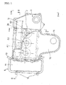
- FIG. 1 Indicated by reference sign 1 in the figures is an internal combustion engine which includes three cylinders A1, A2 and A3 aligned in the direction of a crank axis 2 in the plan view of Fig. 1.
- the internal combustion engine 1 comprises a cylinder block 3, a cylinder head 4 mounted to an upper surface of the cylinder block, and a head cover 5 mounted to cover a valve train (not shown) on the cylinder head 4.
- the head cover 5 is made of heat-resistant synthetic resin.
- the cylinder head 4 includes a longitudinal side surface 4a which extends in parallel with the crank axis 2 in the plan view of Fig. 1.
- an intake manifold 6 is mounted for distributing intake air to the cylinders A1, A2 and A3.
- a throttle body 7 formed with an intake air introduction port 8 which opens upward is mounted on the intake manifold 6.
- the air cleaner 9 is an air cleaner, which is made of the same heat-resistant synthetic resin as the head cover 5.
- the air cleaner 9 includes a lower casing 10 which opens upward, and an upper casing 11 which opens downward.
- the two casings are detachably coupled to each other with a plurality of clip pieces 13, with a filter element 12 interposed therebetween.
- the air cleaner 9 is arranged at an end of the head cover 5 in the direction of the crank axis 2 so that the lower casing 10 of the air cleaner 9 vertically corresponds to the head cover 5 i.e., the lower casing 10 is positioned just beside the head cover 5.
- the lower casing 10 of the air cleaner 9 is integral with the head cover 5.
- the lower casing 10 is formed integrally on the head cover 5 by using the heat-resistant synthetic resin.
- the upper casing 11 of the air cleaner 9 is integrally formed with an atmospheric air introduction pipe 14 having a flared end and an air intake pipe 15, which are formed at the same time as the upper case in molding the upper case 11 using heat-resistant synthetic resin.
- the atmospheric air introduction pipe 14 extends above the head cover 5 along the crank axis 2 toward the opposite end of the head cover 5.
- the air intake pipe 15 has a flat cross section elongated along the upper surface of the head cover 5.
- the air intake pipe extends along the upper surface of the head cover 5 toward the intake manifold 6 without overlapping the atmospheric air introduction pipe 14 .
- the air intake pipe has an end provided with a connection portion 16 which opens downward.
- the connection portion 16 is positioned almost directly above the intake air introduction port 8 of the throttle body 7 and connected to the intake air introduction port 8 via a connection pipe 17 made of an elastic material such as rubber.
- the atmospheric air introduction pipe 14 includes a lower surface formed with a downward opening 18 at a portion connected to the upper casing 11.
- a communication hole 19 for providing communication with the inside of the lower casing 10 is formed at the upper surface thereof.
- a support pin 20 projecting downward is formed integrally on an end of the atmospheric air introduction pipe 14, which is farther from the upper casing 11.
- a bracket 21 is formed integrally on the upper surface of the head cover 5, and a bush 22 made of a soft elastic member such as rubber is mounted to the bracket.
- the support pin 20 projecting downward is removably inserted into the bush 22.
- the support pin 20, the bracket 21 and the bush 22 provide engagement means for removably supporting the atmospheric air introduction pipe 14 relative to the head cover 5.
- the lower casing 10 of the air cleaner 9 constitutes a dust side to which the atmospheric air is introduced as it is, whereas the upper casing 11 constitutes a clean side to which clean air after the filtering by the filter element 12 is introduced.
- the air cleaner 9 is arranged at an end of the head cover 5 in the direction of the crank axis 2 so that the lower casing 10 of the air cleaner 9 vertically corresponds to the head cover 5. Therefore, the height of the portion of the air cleaner 9 which projects upward from the upper surface of the head cover 5 can be reduced by as much as the dimension by which the lower casing 10 of the air cleaner 9 vertically corresponds to the head cover 5.
- the atmospheric air introduction pipe 14 for introducing air to the air cleaner 9 and the air intake pipe 15 for introducing air from the air cleaner 9 to the intake manifold 6 are arranged along the upper surface of the cover 5 so as to extend in the direction of the crank axis 2 without overlapping each other. Therefore, the entire length of the head cover 5 in the direction of the crank axis 2 can be utilized for the arrangement of the atmospheric air introduction pipe 14 for introducing air into the air cleaner 9 and the air intake pipe 15 for sucking air from the air cleaner 9.
- both of the atmospheric air introduction pipe 14 and the air intake pipe 15 can have a length sufficient to enhance the air intake efficiency, while, at the same time, the portion of the atmospheric air introduction pipe 14 which projects out from the internal combustion engine can be made small or eliminated like the example shown in the figures.
- the atmospheric air introduction pipe 14 is supported by the head cover 5 by inserting the support pin 20 into the bush 22 of the head cover 5, the atmospheric air introduction pipe 14 is reliably prevented from vibrating.
- connection pipe 17 made of an elastic material and connecting the end of the air intake pipe 15 integrally formed on the upper casing 11 to the throttle body 7 mounted to the air intake manifold 6 is bent into a dogleg shape.
- the upper casing 11 When the replacement of the filter element 12 is finished, the upper casing 11 is lowered to be positioned relative to the lower casing 10 and coupled to the lower casing with the clip pieces 13.
- the positioning of the upper casing 11 relative to the lower casing 10 can be performed easily and accurately by inserting the support pin 20 of the atmospheric air introduction pipe 14 integrally formed on the upper casing 11 into the bush 22 of the head cover 5.
- connection pipe 17 made of an elastic material can be made generally straight, so that the connection is easy. Further, as noted before, the replacement of the filter element 12 of the air cleaner 9 can be performed without disassembling the connection pipe 17.
- the means for removably engaging the atmospheric air introduction pipe 14 with the cover 5 is not limited to the insertion of the support pin 20 provided at the atmospheric air introduction pipe 14 into the bush 22 provided at the head cover 5, and other structures may be employed.
- the support pin may be provided at the head cover 5, whereas the bush may be provided at the atmospheric air introduction pipe 14.
- the filter element 12 of the air cleaner 9 does not necessarily need to be interposed between the upper and the lower casings 10 and 11 like the foregoing embodiment.
- the filter element may be incorporated in the lower casing 10 or the upper casing 11 so as to be inclined or not to be inclined.
Landscapes
- Engineering & Computer Science (AREA)
- Chemical & Material Sciences (AREA)
- Combustion & Propulsion (AREA)
- Mechanical Engineering (AREA)
- General Engineering & Computer Science (AREA)
- Manufacturing & Machinery (AREA)
- Cylinder Crankcases Of Internal Combustion Engines (AREA)
- Filtering Of Dispersed Particles In Gases (AREA)
Abstract
Description
- The present invention relates to an intake device for guiding atmospheric air to an intake manifold via an air cleaner in an internal combustion engine.
- Generally, this kind of air intake device comprises an air cleaner incorporating a filter element, an atmospheric air introduction pipe for introducing atmospheric air into the air cleaner, and an intake pipe for introducing the air cleaned by the air cleaner into the intake manifold in the internal combustion engine. To enhance the air intake efficiency of the internal combustion engine, the atmospheric air introduction pipe and the intake pipe need to have a sufficient length.
- The Patent Document 1 as a prior art proposes to arrange an air cleaner on a head cover covering the upper surface of a cylinder head in an internal combustion engine. The air cleaner includes two divided parts and a filter element sandwiched therebetween.
- In the structure proposed by the
Patent Document 2 as another prior art, a surge tank in an intake manifold is provided on a head cover covering the upper surface of a cylinder head of an internal combustion engine so that an end of the surge tank projects from a longitudinal end of the head cover. An air cleaner is arranged at a lower surface of the surge tank at a portion which projects from the head cover. - The
Patent Document 3 as another prior art proposes to arrange a casing, which includes two vertically divided parts, on a head cover covering the upper surface of a cylinder head of an internal combustion engine. In the casing, an air cleaner and an atmospheric air introduction pipe for introducing air to the air cleaner are incorporated, and an intake pipe for guiding air from the air cleaner to the intake manifold is provided. - However, to arrange an air cleaner on the upper side of a head cover covering the upper surface of a cylinder head like the Patent Document 1 causes the following problems.
- Since the entirety of the air cleaner projects from the upper surface of the head cover, the total height of the internal combustion engine considerably increases.
- Further, since the atmospheric air introduction pipe needs to have a sufficient length to enhance the air intake efficiency, the atmospheric air introduction pipe projects largely from the internal combustion engine in plan view. Therefore, space for accommodating such a projecting portion needs to be secured around the internal combustion engine.
- Moreover, the intake pipe extending from the air cleaner to the intake manifold cannot have a length sufficient to enhance the air intake efficiency.
- In the structure disclosed in the
Patent Document 2 again, the atmospheric air introduction pipe for introducing air to the air cleaner projects from the internal combustion engine. Therefore, space for accommodating the atmospheric air introduction pipe needs to be secured around the internal combustion engine. Further, an intake passage having a length sufficient to enhance the air intake efficiency cannot be defined between the air cleaner and the surge tank in the intake manifold. - With the structure disclosed in the
Patent Document 3, the entirety of the air cleaner projects from the upper surface of the head cover, similarly to the structure of the Patent Document 1. Therefore, the total height of the internal combustion engine considerably increases. - Patent Document 1:
JP-A 2002-97920 - Patent Document 2:
JP-A 2003-239815 - Patent Document 3:
JP-A 2003-161216 - A technical object of the present invention is to provide an air intake device which is capable of solving the above-described problems, reducing the number of parts and facilitating the replacement of a filter element.
- To achieve the technical object, claim 1 of the present invention provides an air intake device of an internal combustion engine including a cylinder head, an intake manifold provided at a longitudinal side surface of the cylinder head, the side surface extending in parallel with a crank axis of the cylinder head, and a head cover provided on the cylinder head. The air intake device comprises an air cleaner including an upper casing and a lower casing detachably coupled to each other and incorporating a filter element, an atmospheric air introduction pipe for introducing air to the air cleaner, and an intake pipe extending from the air cleaner to the intake manifold. The air cleaner is provided at an end of the head cover in a direction of the crank axis so that the lower casing of the air cleaner vertically corresponds to the head cover. The atmospheric air introduction pipe is arranged above the head cover to extend along an upper surface of the head cover in the direction of the crank axis, whereas the intake pipe is arranged to extend along the upper surface of the head cover toward the intake manifold without overlapping the atmospheric air introduction pipe.
- According to
claim 2 of the present invention, in the structure of claim 1, the intake pipe has a flat cross section elongated along the upper surface of the head cover. - According to
claim 3 of the present invention, in the structure ofclaim 1 or 2, the lower casing of the air cleaner is on a dust side, whereas the upper casing of the air cleaner is on a clean side. The lower casing is formed integrally on the head cover, whereas the atmospheric air introduction pipe and the intake pipe are formed integrally on the upper casing so that the atmospheric air introduction pipe opens into the lower casing. - According to claim 4 of the present invention, in the structure of
claim 3, engagement means for removable engagement is provided between the atmospheric air introduction pipe and the head cover. - According to
claim 5 of the present invention, in the structure ofclaim 3 or 4, the atmospheric air introduction pipe is connected to the intake manifold via a connection pipe made of an elastic material. - With the structure as set forth in claim 1, the height of the portion of the air cleaner which projects upward from the upper surface of the head cover can be reduced by as much as the dimension by which the lower casing of the air cleaner vertically corresponds to the head cover. Therefore, the entire height of the internal combustion engine can be reduced.
- Moreover, the entire length of the head cover in the direction of the crank axis can be utilized for the arrangement of the atmospheric air introduction pipe for introducing air into the air cleaner and the air intake pipe for sucking air from the air cleaner. Therefore, both of the atmospheric air introduction pipe and the air intake pipe can have a length sufficient to enhance the air intake efficiency, while, at the same time, the portion of the atmospheric air introduction pipe which projects from the internal combustion engine can be made small or eliminated.
- Therefore, both of the enhancement of the air intake efficiency and the size reduction of the entire internal combustion engine can be reliably achieved.
- With the structure as set forth in
claim 2, the cross sectional area of the passage in the intake pipe can be increased without increasing the height of the portion of the intake pipe which projects from the upper surface of the head cover. Therefore, the flow resistance in the intake pipe can be reduced, whereby the air intake efficiency can be enhanced. - With the structure as set forth in
claim 3, the lower casing of the air cleaner is formed integrally on the head cover, whereas the atmospheric air introduction pipe and the intake pipe are formed integrally on the upper casing. Therefore, the number of parts is considerably reduced, and the assembling of the parts can be facilitated: Further, the strength of the head cover and the lower casing of the air cleaner can be mutually increased. - Since the lower casing of the air cleaner which is integral with the head cover is on a dust side whereas the upper casing removably coupled to the lower casing is on a clean side, little dust adheres to the upper casing, although much dust adheres to the lower casing. Therefore, scatter of dust in detaching the upper casing to replace the filter element can be kept to a minimum.
- With the structure as set forth in claim 4, the atmospheric air introduction pipe is fixed to the head cover by the engagement means. Therefore, the atmospheric air introduction pipe is reliably prevented from vibrating.
- Moreover, in coupling the upper casing to the lower casing of the air cleaner, the positioning of the upper casing relative to the lower casing can be performed easily and accurately by utilizing the engagement means. Therefore, the replacement of the filter element can be facilitated.
- With the structure as set forth in
claim 5, the upper casing can be lifted from the lower casing while bending the connection pipe made of an elastic material. Therefore, the replacement of the filter element can be performed easily without disassembling the connection pipe. -
- Fig. 1 is a plan view showing an embodiment of the present invention.
- Fig. 2 is a side view taken along lines II-II in Fig. 1.
- Fig. 3 is a sectional view taken along lines III-III in Fig. 1.
- Fig. 4 shows the exploded view of Fig. 3.
- Fig. 5 is an enlarged sectional view taken along lines V-V in Fig. 1.
-
- 1
- internal combustion engine
- 2
- crank axis
- 4
- cylinder head
- 5
- head cover
- 6
- intake manifold
- 7
- throttle body
- 9
- air cleaner
- 10
- lower casing
- 11
- upper casing
- 12
- filter element
- 14
- atmospheric air introduction pipe
- 15
- intake pipe
- 17
- connection pipe
- 20
- support pin
- 21
- bracket
- 22
- bush
- Preferred embodiments of the present invention will be described below with reference to the accompanying drawings.
- Indicated by reference sign 1 in the figures is an internal combustion engine which includes three cylinders A1, A2 and A3 aligned in the direction of a
crank axis 2 in the plan view of Fig. 1. - The internal combustion engine 1 comprises a
cylinder block 3, a cylinder head 4 mounted to an upper surface of the cylinder block, and ahead cover 5 mounted to cover a valve train (not shown) on the cylinder head 4. - The
head cover 5 is made of heat-resistant synthetic resin. The cylinder head 4 includes alongitudinal side surface 4a which extends in parallel with thecrank axis 2 in the plan view of Fig. 1. To theside surface 4a, anintake manifold 6 is mounted for distributing intake air to the cylinders A1, A2 and A3. Athrottle body 7 formed with an intakeair introduction port 8 which opens upward is mounted on theintake manifold 6. - Indicated by reference sign 9 is an air cleaner, which is made of the same heat-resistant synthetic resin as the
head cover 5. The air cleaner 9 includes alower casing 10 which opens upward, and anupper casing 11 which opens downward. The two casings are detachably coupled to each other with a plurality ofclip pieces 13, with afilter element 12 interposed therebetween. - In the plan view of Fig. 1, the air cleaner 9 is arranged at an end of the
head cover 5 in the direction of thecrank axis 2 so that thelower casing 10 of the air cleaner 9 vertically corresponds to thehead cover 5 i.e., thelower casing 10 is positioned just beside thehead cover 5. - The
lower casing 10 of the air cleaner 9 is integral with thehead cover 5. - Specifically, the
lower casing 10 is formed integrally on thehead cover 5 by using the heat-resistant synthetic resin. - The
upper casing 11 of the air cleaner 9 is integrally formed with an atmosphericair introduction pipe 14 having a flared end and anair intake pipe 15, which are formed at the same time as the upper case in molding theupper case 11 using heat-resistant synthetic resin. - The atmospheric
air introduction pipe 14 extends above thehead cover 5 along thecrank axis 2 toward the opposite end of thehead cover 5. Theair intake pipe 15 has a flat cross section elongated along the upper surface of thehead cover 5. The air intake pipe extends along the upper surface of thehead cover 5 toward theintake manifold 6 without overlapping the atmosphericair introduction pipe 14 . The air intake pipe has an end provided with aconnection portion 16 which opens downward. Theconnection portion 16 is positioned almost directly above the intakeair introduction port 8 of thethrottle body 7 and connected to the intakeair introduction port 8 via aconnection pipe 17 made of an elastic material such as rubber. - The atmospheric
air introduction pipe 14 includes a lower surface formed with adownward opening 18 at a portion connected to theupper casing 11. On the other hand, at a connection portion of thehead cover 5 to thelower casing 10, acommunication hole 19 for providing communication with the inside of thelower casing 10 is formed at the upper surface thereof. When theupper casing 11 is coupled to thelower casing 10 with thefilter element 12 interposed therebetween, thedownward opening 18 of the atmosphericair introduction pipe 14 is connected to thecommunication hole 19 for thelower casing 10. Therefore, the atmosphericair introduction pipe 14 communicates with the inside of thelower casing 10 via theopening 18 and thecommunication hole 19. - A
support pin 20 projecting downward is formed integrally on an end of the atmosphericair introduction pipe 14, which is farther from theupper casing 11. On the other hand, abracket 21 is formed integrally on the upper surface of thehead cover 5, and abush 22 made of a soft elastic member such as rubber is mounted to the bracket. Thesupport pin 20 projecting downward is removably inserted into thebush 22. - The
support pin 20, thebracket 21 and thebush 22 provide engagement means for removably supporting the atmosphericair introduction pipe 14 relative to thehead cover 5. - With this structure, when the atmospheric air is introduced into the
lower casing 10 of the air cleaner 9 through the atmosphericair introduction pipe 14 and then into theupper casing 11 through thefilter element 12, dust is filtered out by thefilter element 12, whereby the air is cleaned. The cleaned air flows from theupper casing 11 to theintake manifold 6 through theair intake pipe 15 and is then sucked from theintake manifold 6 into each of the cylinders A1, A2 and A3. - In this structure, the
lower casing 10 of the air cleaner 9 constitutes a dust side to which the atmospheric air is introduced as it is, whereas theupper casing 11 constitutes a clean side to which clean air after the filtering by thefilter element 12 is introduced. - The air cleaner 9 is arranged at an end of the
head cover 5 in the direction of thecrank axis 2 so that thelower casing 10 of the air cleaner 9 vertically corresponds to thehead cover 5. Therefore, the height of the portion of the air cleaner 9 which projects upward from the upper surface of thehead cover 5 can be reduced by as much as the dimension by which thelower casing 10 of the air cleaner 9 vertically corresponds to thehead cover 5. - Further, the atmospheric
air introduction pipe 14 for introducing air to the air cleaner 9 and theair intake pipe 15 for introducing air from the air cleaner 9 to theintake manifold 6 are arranged along the upper surface of thecover 5 so as to extend in the direction of thecrank axis 2 without overlapping each other. Therefore, the entire length of thehead cover 5 in the direction of thecrank axis 2 can be utilized for the arrangement of the atmosphericair introduction pipe 14 for introducing air into the air cleaner 9 and theair intake pipe 15 for sucking air from the air cleaner 9. Therefore, both of the atmosphericair introduction pipe 14 and theair intake pipe 15 can have a length sufficient to enhance the air intake efficiency, while, at the same time, the portion of the atmosphericair introduction pipe 14 which projects out from the internal combustion engine can be made small or eliminated like the example shown in the figures. - Since the atmospheric
air introduction pipe 14 is supported by thehead cover 5 by inserting thesupport pin 20 into thebush 22 of thehead cover 5, the atmosphericair introduction pipe 14 is reliably prevented from vibrating. - To replace the
filter element 12 of the air cleaner 9, theclip pieces 13 coupling theupper casing 10 and thelower casing 11 are removed, and theupper casing 11 is lifted, as indicated by double dashed lines in Fig. 2. In lifting theupper casing 11, theconnection pipe 17 made of an elastic material and connecting the end of theair intake pipe 15 integrally formed on theupper casing 11 to thethrottle body 7 mounted to theair intake manifold 6 is bent into a dogleg shape. - When the replacement of the
filter element 12 is finished, theupper casing 11 is lowered to be positioned relative to thelower casing 10 and coupled to the lower casing with theclip pieces 13. The positioning of theupper casing 11 relative to thelower casing 10 can be performed easily and accurately by inserting thesupport pin 20 of the atmosphericair introduction pipe 14 integrally formed on theupper casing 11 into thebush 22 of thehead cover 5. - The
upper casing 11 of the air cleaner 9, which is moved for attachment to or detachment from thelower casing 10, is on the clean side, and little dust adheres to the upper casing. Therefore, the detachment of theupper casing 11 to replace thefilter element 12 hardly causes scatter of dust. - Since the intake
air introduction port 8 of thethrottle body 7 mounted to theair intake manifold 6 is oriented upward whereas theconnection portion 16 at the end of theair intake pipe 15 from the air cleaner 9 is oriented downward and positioned directly above the intakeair introduction port 8, theconnection pipe 17 made of an elastic material can be made generally straight, so that the connection is easy. Further, as noted before, the replacement of thefilter element 12 of the air cleaner 9 can be performed without disassembling theconnection pipe 17. - The means for removably engaging the atmospheric
air introduction pipe 14 with thecover 5 is not limited to the insertion of thesupport pin 20 provided at the atmosphericair introduction pipe 14 into thebush 22 provided at thehead cover 5, and other structures may be employed. For instance, the support pin may be provided at thehead cover 5, whereas the bush may be provided at the atmosphericair introduction pipe 14. - The
filter element 12 of the air cleaner 9 does not necessarily need to be interposed between the upper and thelower casings lower casing 10 or theupper casing 11 so as to be inclined or not to be inclined.
Claims (5)
- An air intake device of an internal combustion engine including a cylinder head, an intake manifold provided at a longitudinal side surface of the cylinder head, the side surface extending in parallel with a crank axis of the cylinder head, and a head cover provided on the cylinder head, the air intake device comprising: an air cleaner including an upper casing and a lower casing detachably coupled to each other and incorporating a filter element, an atmospheric air introduction pipe for introducing air to the air cleaner, and an intake pipe extending from the air cleaner to the intake manifold;
wherein the air cleaner is provided at an end of the head cover in a direction of the crank axis so that the lower casing of the air cleaner vertically corresponds to the head cover, and wherein, the atmospheric air introduction pipe is arranged above the head cover to extend along an upper surface of the head cover in the direction of the crank axis, whereas the intake pipe is arranged to extend along the upper surface of the head cover toward the intake manifold without overlapping the atmospheric air introduction pipe. - The air intake device of internal combustion engine according to claim 1, wherein the intake pipe has a flat cross section elongated along the upper surface of the head cover.
- The air intake device of internal combustion engine according to claim 1 or 2, wherein the lower casing of the air cleaner is on a dust side, whereas the upper casing of the air cleaner is on a clean side, and wherein the lower casing is formed integrally on the head cover, whereas the atmospheric air introduction pipe and the intake pipe are formed integrally on the upper casing so that the atmospheric air introduction pipe opens into the lower casing.
- The air intake device of internal combustion engine according to claim 3, wherein engagement means for removable engagement is provided between the atmospheric air introduction pipe and the head cover.
- The air intake device of internal combustion engine according to claim 3 or 4, wherein the atmospheric air introduction pipe is connected to the intake manifold via a connection pipe made of an elastic material.
Applications Claiming Priority (2)
| Application Number | Priority Date | Filing Date | Title |
|---|---|---|---|
| JP2004163276A JP4480472B2 (en) | 2004-06-01 | 2004-06-01 | Intake device for internal combustion engine |
| PCT/JP2005/003272 WO2005119043A1 (en) | 2004-06-01 | 2005-02-28 | Air intake device of internal combustion engine |
Publications (3)
| Publication Number | Publication Date |
|---|---|
| EP1752650A1 true EP1752650A1 (en) | 2007-02-14 |
| EP1752650A4 EP1752650A4 (en) | 2010-09-01 |
| EP1752650B1 EP1752650B1 (en) | 2012-06-27 |
Family
ID=35462966
Family Applications (1)
| Application Number | Title | Priority Date | Filing Date |
|---|---|---|---|
| EP05719600A Ceased EP1752650B1 (en) | 2004-06-01 | 2005-02-28 | Air intake device of internal combustion engine |
Country Status (5)
| Country | Link |
|---|---|
| US (1) | US7392784B2 (en) |
| EP (1) | EP1752650B1 (en) |
| JP (1) | JP4480472B2 (en) |
| CN (1) | CN100570149C (en) |
| WO (1) | WO2005119043A1 (en) |
Families Citing this family (14)
| Publication number | Priority date | Publication date | Assignee | Title |
|---|---|---|---|---|
| DE202006011027U1 (en) * | 2006-07-14 | 2007-12-20 | Mann+Hummel Gmbh | Suction device for an internal combustion engine |
| JP4858710B2 (en) * | 2007-05-14 | 2012-01-18 | スズキ株式会社 | Engine intake system |
| JP5351588B2 (en) * | 2009-03-31 | 2013-11-27 | 本田技研工業株式会社 | Intake passage structure of internal combustion engine |
| JP5365405B2 (en) * | 2009-08-06 | 2013-12-11 | トヨタ自動車株式会社 | Engine intake system |
| JP5451491B2 (en) * | 2010-03-31 | 2014-03-26 | 本田技研工業株式会社 | vehicle |
| DE102010024656A1 (en) | 2010-06-22 | 2011-12-22 | Mann + Hummel Gmbh | Air filter device of combustion engine, has raw air line and pure air line that are combined to form common pipeline which comprises filter cover with receiving opening into which filter insert is introduced |
| JP5913083B2 (en) * | 2012-12-26 | 2016-04-27 | 本田技研工業株式会社 | Vehicle intake passage structure |
| JP6501184B2 (en) * | 2015-04-30 | 2019-04-17 | ダイハツ工業株式会社 | Internal combustion engine for vehicles |
| US9551307B1 (en) | 2015-07-21 | 2017-01-24 | Ford Global Technologies, Llc | Hinged engine cover for intake manifold |
| US9840989B2 (en) | 2015-11-30 | 2017-12-12 | Ford Global Technologies, Llc | Soft engine cover for intake manifold |
| US9964065B2 (en) * | 2015-12-03 | 2018-05-08 | Kawasaki Jukogyo Kabushiki Kaisha | General purpose engine |
| JP6790809B2 (en) | 2016-12-26 | 2020-11-25 | トヨタ紡織株式会社 | Internal combustion engine air cleaner |
| US11047349B2 (en) * | 2017-08-09 | 2021-06-29 | Honda Motor Co., Ltd. | Intake structure of engine |
| KR102370942B1 (en) * | 2017-09-14 | 2022-03-07 | 현대자동차주식회사 | Adapter Filter Fixing type Air Cleaner and Intake System thereby |
Family Cites Families (17)
| Publication number | Priority date | Publication date | Assignee | Title |
|---|---|---|---|---|
| DE523395C (en) * | 1931-04-23 | Anton Schlueter Motorenfabrik | Four-stroke injection internal combustion engine controlled from above | |
| CH282919A (en) * | 1949-07-29 | 1952-05-15 | Daimler Benz Ag | Device on motor vehicles for supplying fresh air from the front of the vehicle to the engine. |
| JPH01102469U (en) * | 1987-07-24 | 1989-07-11 | ||
| JPH01102469A (en) | 1987-10-15 | 1989-04-20 | Fuji Electric Co Ltd | Electrophotographic sensitive body |
| JPH04104134A (en) | 1990-08-24 | 1992-04-06 | Mitsubishi Electric Corp | Overhead projector |
| JP2516513Y2 (en) * | 1991-02-12 | 1996-11-06 | ダイハツ工業株式会社 | Internal combustion engine intake system |
| JP3362592B2 (en) * | 1996-01-31 | 2003-01-07 | スズキ株式会社 | Intake device for internal combustion engine |
| CN2249308Y (en) * | 1996-02-26 | 1997-03-12 | 黄钊仁 | Air cleaner for motor vehicle |
| JP3528430B2 (en) * | 1996-04-30 | 2004-05-17 | スズキ株式会社 | Vehicle air cleaner support structure |
| JP3442627B2 (en) | 1997-10-21 | 2003-09-02 | ダイハツ工業株式会社 | Air cleaner duct support structure |
| JPH11294280A (en) * | 1998-04-13 | 1999-10-26 | Honda Motor Co Ltd | Engine intake system |
| EP1182343B1 (en) * | 2000-08-25 | 2006-09-27 | Daihatsu Motor Co., Ltd. | Arrangement of cylinder head cover for internal combustion engine |
| JP2002097920A (en) | 2000-09-22 | 2002-04-05 | Daihatsu Motor Co Ltd | Blow-by gas extraction device for internal combustion engine |
| JP3739687B2 (en) | 2001-10-22 | 2006-01-25 | 本田技研工業株式会社 | Balancer shaft housing |
| JP2003161216A (en) * | 2001-11-28 | 2003-06-06 | Toyoda Gosei Co Ltd | Intake unit |
| JP3864100B2 (en) * | 2002-02-18 | 2006-12-27 | 日産自動車株式会社 | Intake device for internal combustion engine |
| JP4539470B2 (en) * | 2005-07-12 | 2010-09-08 | スズキ株式会社 | Engine intake system |
-
2004
- 2004-06-01 JP JP2004163276A patent/JP4480472B2/en not_active Expired - Fee Related
-
2005
- 2005-02-28 US US11/628,070 patent/US7392784B2/en not_active Expired - Lifetime
- 2005-02-28 CN CNB2005800050809A patent/CN100570149C/en not_active Expired - Fee Related
- 2005-02-28 EP EP05719600A patent/EP1752650B1/en not_active Ceased
- 2005-02-28 WO PCT/JP2005/003272 patent/WO2005119043A1/en not_active Ceased
Also Published As
| Publication number | Publication date |
|---|---|
| CN100570149C (en) | 2009-12-16 |
| JP2005344555A (en) | 2005-12-15 |
| WO2005119043A1 (en) | 2005-12-15 |
| JP4480472B2 (en) | 2010-06-16 |
| EP1752650B1 (en) | 2012-06-27 |
| US20070193554A1 (en) | 2007-08-23 |
| EP1752650A4 (en) | 2010-09-01 |
| US7392784B2 (en) | 2008-07-01 |
| CN1922400A (en) | 2007-02-28 |
Similar Documents
| Publication | Publication Date | Title |
|---|---|---|
| US7392784B2 (en) | Air intake device of internal combustion engine | |
| JP5142781B2 (en) | Motorcycle | |
| CN101509446B (en) | Air feeder structure of internal combustion engine | |
| US9016414B2 (en) | Air cleaner device for vehicle | |
| CN101490401A (en) | delivery unit for delivery of fuel | |
| CN102030061B (en) | Scooter-type vehicle | |
| EP2233186A3 (en) | Vehicle fuel supply device and fuel filter structure | |
| EP2138701A2 (en) | Air cleaner for internal combustion | |
| CA1258015A (en) | Air silencer for an internal combustion engine | |
| CN100350149C (en) | Connecting structure of fuel filter and fuel pump | |
| CN101113709B (en) | Fuel supply device for motocycles | |
| CN100394019C (en) | Air inlet structure for engine | |
| CN102734008B (en) | Induction manifold used for combustion engine | |
| EP1182343A2 (en) | Arrangement of cylinder head cover for internal combustion engine | |
| JP3853582B2 (en) | Structure of cylinder head cover in internal combustion engine | |
| JP2010031830A (en) | Lpi fuel supply system | |
| CN101268253B (en) | Manifold gasket with pushrod guide | |
| CN2793358Y (en) | Ram sleeve | |
| JP4533722B2 (en) | Intake device for slant type internal combustion engine | |
| EP1683959A1 (en) | Air cleaner structure for vehicle | |
| CN211397684U (en) | A kind of oil and gas fine separator | |
| JPH11247727A (en) | Device for introducing blowby gas or the like of internal combustion engine to intake system | |
| KR101272943B1 (en) | Air intake apparatus for vehicle | |
| JP2012041885A (en) | Device for mounting of injector in internal combustion engine | |
| CN2506781Y (en) | Integral fuel filter |
Legal Events
| Date | Code | Title | Description |
|---|---|---|---|
| PUAI | Public reference made under article 153(3) epc to a published international application that has entered the european phase |
Free format text: ORIGINAL CODE: 0009012 |
|
| 17P | Request for examination filed |
Effective date: 20061218 |
|
| AK | Designated contracting states |
Kind code of ref document: A1 Designated state(s): DE FR GB |
|
| DAX | Request for extension of the european patent (deleted) | ||
| RBV | Designated contracting states (corrected) |
Designated state(s): DE FR GB |
|
| A4 | Supplementary search report drawn up and despatched |
Effective date: 20100804 |
|
| 17Q | First examination report despatched |
Effective date: 20101222 |
|
| REG | Reference to a national code |
Ref country code: DE Ref legal event code: R079 Ref document number: 602005034929 Country of ref document: DE Free format text: PREVIOUS MAIN CLASS: F02M0035040000 Ipc: F02M0035020000 |
|
| GRAP | Despatch of communication of intention to grant a patent |
Free format text: ORIGINAL CODE: EPIDOSNIGR1 |
|
| RIC1 | Information provided on ipc code assigned before grant |
Ipc: F02M 35/04 20060101ALI20111202BHEP Ipc: F02M 35/10 20060101ALI20111202BHEP Ipc: F02M 35/02 20060101AFI20111202BHEP |
|
| GRAS | Grant fee paid |
Free format text: ORIGINAL CODE: EPIDOSNIGR3 |
|
| GRAA | (expected) grant |
Free format text: ORIGINAL CODE: 0009210 |
|
| AK | Designated contracting states |
Kind code of ref document: B1 Designated state(s): DE FR GB |
|
| REG | Reference to a national code |
Ref country code: GB Ref legal event code: FG4D |
|
| REG | Reference to a national code |
Ref country code: DE Ref legal event code: R096 Ref document number: 602005034929 Country of ref document: DE Effective date: 20120823 |
|
| RAP2 | Party data changed (patent owner data changed or rights of a patent transferred) |
Owner name: DAIHATSU MOTOR CO., LTD. Owner name: TOYOTA JIDOSHA KABUSHIKI KAISHA Owner name: TOYOTA BOSHOKU KABUSHIKI KAISHA |
|
| PLBE | No opposition filed within time limit |
Free format text: ORIGINAL CODE: 0009261 |
|
| STAA | Information on the status of an ep patent application or granted ep patent |
Free format text: STATUS: NO OPPOSITION FILED WITHIN TIME LIMIT |
|
| 26N | No opposition filed |
Effective date: 20130328 |
|
| REG | Reference to a national code |
Ref country code: DE Ref legal event code: R097 Ref document number: 602005034929 Country of ref document: DE Effective date: 20130328 |
|
| REG | Reference to a national code |
Ref country code: FR Ref legal event code: PLFP Year of fee payment: 12 |
|
| REG | Reference to a national code |
Ref country code: FR Ref legal event code: PLFP Year of fee payment: 13 |
|
| REG | Reference to a national code |
Ref country code: FR Ref legal event code: PLFP Year of fee payment: 14 |
|
| PGFP | Annual fee paid to national office [announced via postgrant information from national office to epo] |
Ref country code: FR Payment date: 20210113 Year of fee payment: 17 |
|
| PGFP | Annual fee paid to national office [announced via postgrant information from national office to epo] |
Ref country code: DE Payment date: 20210216 Year of fee payment: 17 Ref country code: GB Payment date: 20210217 Year of fee payment: 17 |
|
| REG | Reference to a national code |
Ref country code: DE Ref legal event code: R119 Ref document number: 602005034929 Country of ref document: DE |
|
| GBPC | Gb: european patent ceased through non-payment of renewal fee |
Effective date: 20220228 |
|
| PG25 | Lapsed in a contracting state [announced via postgrant information from national office to epo] |
Ref country code: FR Free format text: LAPSE BECAUSE OF NON-PAYMENT OF DUE FEES Effective date: 20220228 |
|
| PG25 | Lapsed in a contracting state [announced via postgrant information from national office to epo] |
Ref country code: GB Free format text: LAPSE BECAUSE OF NON-PAYMENT OF DUE FEES Effective date: 20220228 Ref country code: DE Free format text: LAPSE BECAUSE OF NON-PAYMENT OF DUE FEES Effective date: 20220901 |