EP1752558A1 - Film forming apparatus - Google Patents
Film forming apparatus Download PDFInfo
- Publication number
- EP1752558A1 EP1752558A1 EP05720487A EP05720487A EP1752558A1 EP 1752558 A1 EP1752558 A1 EP 1752558A1 EP 05720487 A EP05720487 A EP 05720487A EP 05720487 A EP05720487 A EP 05720487A EP 1752558 A1 EP1752558 A1 EP 1752558A1
- Authority
- EP
- European Patent Office
- Prior art keywords
- section
- film forming
- forming apparatus
- face
- hole
- Prior art date
- Legal status (The legal status is an assumption and is not a legal conclusion. Google has not performed a legal analysis and makes no representation as to the accuracy of the status listed.)
- Withdrawn
Links
Images


Classifications
-
- C—CHEMISTRY; METALLURGY
- C23—COATING METALLIC MATERIAL; COATING MATERIAL WITH METALLIC MATERIAL; CHEMICAL SURFACE TREATMENT; DIFFUSION TREATMENT OF METALLIC MATERIAL; COATING BY VACUUM EVAPORATION, BY SPUTTERING, BY ION IMPLANTATION OR BY CHEMICAL VAPOUR DEPOSITION, IN GENERAL; INHIBITING CORROSION OF METALLIC MATERIAL OR INCRUSTATION IN GENERAL
- C23C—COATING METALLIC MATERIAL; COATING MATERIAL WITH METALLIC MATERIAL; SURFACE TREATMENT OF METALLIC MATERIAL BY DIFFUSION INTO THE SURFACE, BY CHEMICAL CONVERSION OR SUBSTITUTION; COATING BY VACUUM EVAPORATION, BY SPUTTERING, BY ION IMPLANTATION OR BY CHEMICAL VAPOUR DEPOSITION, IN GENERAL
- C23C14/00—Coating by vacuum evaporation, by sputtering or by ion implantation of the coating forming material
- C23C14/22—Coating by vacuum evaporation, by sputtering or by ion implantation of the coating forming material characterised by the process of coating
- C23C14/34—Sputtering
-
- H—ELECTRICITY
- H01—ELECTRIC ELEMENTS
- H01J—ELECTRIC DISCHARGE TUBES OR DISCHARGE LAMPS
- H01J37/00—Discharge tubes with provision for introducing objects or material to be exposed to the discharge, e.g. for the purpose of examination or processing thereof
- H01J37/32—Gas-filled discharge tubes
- H01J37/32431—Constructional details of the reactor
- H01J37/32458—Vessel
-
- H—ELECTRICITY
- H01—ELECTRIC ELEMENTS
- H01J—ELECTRIC DISCHARGE TUBES OR DISCHARGE LAMPS
- H01J37/00—Discharge tubes with provision for introducing objects or material to be exposed to the discharge, e.g. for the purpose of examination or processing thereof
- H01J37/32—Gas-filled discharge tubes
- H01J37/34—Gas-filled discharge tubes operating with cathodic sputtering
- H01J37/3411—Constructional aspects of the reactor
- H01J37/3435—Target holders (includes backing plates and endblocks)
Definitions
- the present invention relates to a film forming apparatus, and more particularly, to a film forming apparatus capable of performing film formation on a substrate that is left in a die without being removed therefrom after molding forming.
- film formation processing is done with a substrate mounted on a carrier for use in a film forming apparatus or a film forming apparatus itself. Therefore, a substrate for e.g., a lamp reflector for automobiles etc. is removed from the dies after molding forming and then mounted on a film forming apparatus or the like to form a film on it.
- a substrate for e.g., a lamp reflector for automobiles etc. is removed from the dies after molding forming and then mounted on a film forming apparatus or the like to form a film on it.
- the conventional film forming apparatus require, after molding forming, the preparatory steps of removing the substrate from the dies and mounting it on the film forming apparatus or the like.
- a primary object of the invention is to provide a film forming apparatus capable of obviating the need for the preparatory steps, i.e., the removal of a substrate from the dies and mounting of it on the film forming apparatus or the like, by performing film formation on a substrate left in a molding die, thereby reducing the number of steps of processing a product and, in consequence, the processing time and cost of the product.
- the target may be disposed so as to be electrically insulated from the wall portion (claim 2).
- the bottom part may be electrically conductive (claim 3). This enables potential application to the target through the bottom part, so that the electric system of the film forming apparatus can be simplified.
- An electric connection terminal may be disposed at an outer surface of the bottom part (claim 4).
- a gate valve may be disposed in the wall portion so as to open and close a communication between the opened end of the frame and the target (claim 5). This enables it to form a preliminary closed space surrounding the main face of the target, so that the time required for vacuuming can be reduced and the target can be protected.
- the film forming apparatus may further comprise:
- the apparatus section may include a magnet and a cooling system which are located behind the target (claim 7). With this arrangement, magnetron sputtering can be carried out.
- a contact-proof portion may be formed on the outer surface of the frame surrounding the through hole of the adaptor section, for covering a specified part of the substrate when the joint face of the adaptor section comes into contact with the die joint face that surrounds the substrate left in the die (claim 8). This makes it possible to exclude the specified part from the area subjected to film formation.
- a piping having a valve, a depressurization chamber and a vacuum pump is connected to the port, and this piping is so formed as to selectively change connection between the vacuum pump and the depressurization chamber (claim 9).
- the depressurization chamber enables a reduction in the time required for vacuuming.
- the invention has such an effect that since film formation processing can be performed on a substrate that is left on a molding die without being removed therefrom after molding forming, the number of steps of processing a product and, therefore, the processing time and cost for the product can be reduced.
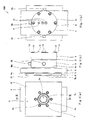
- Fig. 1 is views schematically illustrating a film forming apparatus 100 according to a first embodiment of the invention, wherein Figs. 1(a), 1(b), 1(c) are a front view, side view and rear view, respectively.
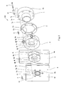
- Fig. 2 is an exploded perspective view illustrating a connecting structure of the film forming apparatus 100 shown in Fig. 1.
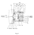
- Fig. 3 is a sectional view taken along line III-III of Fig. 1, which illustrates a joining structure of the film forming apparatus 100, a die P and a substrate W. It should be noted that Fig. 3 shows only some screws 7, 8, 9 and insulating guide 11 and omits their identical screws etc.
- the film forming apparatus 100 is formed in the shape of a cylinder, on the whole, that is closed by a bottom part (i.e., apparatus section 1) at an end thereof and opened at the other end thereof.
- a target 1a is disposed at the inner surface of the bottom part and an annular joint face is formed at an end face 5f on the opened side.
- the target 1a is formed so as to be electrically insulated from a wall face defining an inner hole 2c, a wall face defining an inner hole 3c, a wall face defining a through hole 4c, a wall face defining a through hole 5c and the end face 5f on the opened side.
- the film forming apparatus 100 has one or a plurality of ports 3a that make a closed space B communicate with the outside of the film forming apparatus 100.
- the film forming apparatus 100 is made up of separated parts, i.e., the apparatus section 1, an insulating spacer 2, a port section 3, a gate valve section 4, and an adaptor section 5. These parts are integrated, being fastened to one another by means of bolts 7, 8, 9, such that the main face of the target 1a of the apparatus section 1, the inner hole 2c of the spacer 2, the inner hole 3c of the port section 3, the through hole 4c of the gate valve section 4 and the through hole 5c of the adaptor section 5 have a common central axis 50.
- the closed space B is formed in the shape of a column which bottom face is defined by the target 1a.
- these members are integrated with seal members (not shown) such as O-rings interposed between their joint faces, so that the closed space B has an air tight structure.
- the apparatus section 1 has a frame 1h made of a rigid material. As illustrated in Fig. 3, the frame 1h takes the form of a stepped cylinder in which a small diameter portion projects from the front end face of a large diameter portion and the small and large diameter portions have the central axis 50 as their common axis.
- the target 1a is disposed at the front end face of the small diameter portion. Specifically, a recess portion 15 having a stepped portion 15a is formed at the front end face of the small diameter portion and the target 1a is liquid-tightly disposed in the stepped portion 15a.
- a magnet 1b is placed, with a gap (coolant passage 1c) between the magnet 1b and the inner surface of the recess portion 15.
- a pair of coolant passages 1p extend from the bottom face of the recess portion 15 to the rear end face of the large diameter portion.
- a pair of coolant pipe connection portions 1d are provided in the openings of the pair of coolant passages 1p respectively so as to project from the rear end face of the large diameter portion, that is, the rear face of the apparatus section 1.
- One of the coolant pipe connection portions 1d is an inlet for the coolant whereas the other is an outlet for the coolant.
- the stepped portion of the apparatus section 1 constitutes a joint face 1e.
- Formed at the joint face 1e are a plurality of bolt insertion holes 1g that pass through the large diameter portion.
- the frame 1h Projectingly formed at the rear face of the frame 1h is an electric connection terminal 1f that is electrically connected to the target 1a.
- the frame 1h is made of a metal having high electric conductivity, so that the electric connection terminal 1f and the target 1a are electrically connected to each other.
- the port section 3 is cylindrical in shape.
- a first end face 3e which is the rear end face of the port section 3, has an annular shape joinable to the joint face 1e of the apparatus section 1. More specifically, the first end face 3e has substantially the same outer diameter as of the large diameter portion of the apparatus section 1 and larger inner diameter (the diameter of the inner hole 3c) than the small diameter portion of the apparatus section 1.
- threaded holes 3g are so formed as to correspond to the bolt insertion holes 1g of the apparatus section 1.
- the ports 3a are so formed as to pierce the wall portion of the port section 3. While three ports 3a are formed herein, being aligned in a circumferential direction, one or a plurality of ports 3a may be used.
- Pipe connection portions 3b are provided in the openings of the ports 3a that pass through the outer circumferential face of the port section 3.
- the wall portion of the port section 3 includes an extending portion that inwardly extends from the front end of the port section 3, and a plurality of bolt insertion holes 3j are so formed as to penetrate this extending portion.
- the insulating spacer 2 is in the form of a hollow disk having substantially the same outer diameter and inner diameter (the diameter of the inner hole 2c) as of the first end face 3e of the port section 3. Formed in the insulating spacer 2 are bolt insertion holes 2g that correspond to the bolt insertion holes 1g of the apparatus section 1.
- the insulating spacer 2 is made of an electrically insulating elastic material such as a rubber packing, in order to electrically insulate and seal between the joint face 1e of the apparatus section 1 and the first end face 3e of the port section 3.
- the apparatus section 1 and the port section 3 are integrally fastened to each other by bolts 9 with the insulating spacer 2 being interposed between the joint face 1e and the first end face 3e.
- the apparatus section 1 and the port section 3 are not in direct contact with each other but arranged such that the insulating spacer 2 is present in all the spaces between the joint face 1e and the first end face 3e which are opposed to each other.
- electrically insulating guides 11 in the form of a cylinder having a collar are used.
- each insulating guide 11 is inserted into the bolt insertion holes 1g, 2g and each bolt 9 is screwed into and stopped at a threaded hole 3g of the port section 3, after passing through the insulating guide 11. This prevents electrical continuity between the apparatus section 1 and the port section 3 through the bolts 9.
- the entire gate valve section 4 is the form of a rectangular plate having a through hole 4c at the center thereof.
- a plate-shaped valve body movement space 4b that traverses the through hole 4c.
- a plate-shaped valve body 4a is accommodated so as to be slidable in the valve body movement space 4b, thereby opening and closing the through hole 4c.
- the valve body 4a is connected to an actuator (not shown) such as a piston rod for air cylinders and is slidingly actuated by this actuator, thereby opening and closing the through hole 4c.
- the sliding part between the actuator and the gate valve section is properly sealed so that the valve body movement space 4b is kept hermetic relative to the outside and therefore outside air does not penetrate when the valve body 4a is in sliding movement.
- the through hole 4c is formed so as to have a larger cross-sectional area than a film forming face Wa of a substrate W.
- Boss portions 4n, 4m are arranged so as to surround both openings of the through hole 4c, respectively.
- the end faces of the boss portions 4n, 4m constitute joint faces 4e, 4f, respectively.
- threaded holes 4j are formed so as to correspond to the bolt insertion holes 3j of the port section 3.
- threaded holes 4k are formed.
- the gate valve section 4 of the first embodiment is constituted by the known gate valve (high-vacuum gate valve (with a protect ring) produced by VAT SKK VACUUM Ltd.) for use in vacuum equipment.
- the gate valve section 4 is integrally fastened to the port section 3 by bolts 8 such that the through hole 4c and the inner hole 3c have the central axis 50 as their common axis and the joint face 4e is joined to a second joint face 3f of the port section 3.
- Each bolt 8 is screwed into and stopped at a threaded hole 4j of the gate valve section 4, after passing through the bolt insertion hole 3j of the port section 3.
- the joint part where the second end face 3f of the port section 3 and the joint face 4e of the gate valve section 4 are joined is sealed by a sealing member (not shown).
- the adaptor section 5 is formed in the shape of a square plate and has the through hole 5c formed at the center thereof.
- a first face 5e which is the rear face of the adaptor section 5, constitutes a joint face joined to a joint face 4f of the gate valve section 4.
- the second face 5f which is the front face of the adaptor section 5, constitutes a joint face to be joined to a joint face Pa of a die P.
- the second face 5f has an annular contact-proof portion 5a that surrounds the opening of the through hole 5c.
- the joint face Pa of the die P is provided with a molding cavity 61 in which the substrate W is molded.
- the opening of the through hole 5c of the adaptor section 5 is formed such that when the adaptor section 5 is joined to the die P, the surface Wa (hereinafter referred to as "film forming face") of the substrate W on which a film is to be formed is exposed to the through hole 5c (i.e., the closed space B of the film forming apparatus 100).
- the wall face defining the through hole 5c is formed so as to coincide with the outer periphery of the film forming face Wa such that film formation does not take place in the die joint face Pa.
- the annular contact-proof portion 5a is provided on the rim of the through hole 5c of the adaptor section 5 so as to come into contact with the non-filmed face of the substrate W to cover it when the adaptor section 5 is joined to the die P.
- the non-filmed face of the substrate W is the joint faces of a substrate that is joined to other parts. In molding the substrate W, the outer periphery of the substrate W is sometimes formed in a position anterior to the die joint face Pa (based on the drawings), that is, a position set back from the die joint face Pa. Therefore, the contact-proof portion 5a is convex in shape.
- the second face 5f of the adaptor section 5 is provided with spot facings (concave portions) that are located at positions corresponding to the threaded holes 4k of the gate valve section 4, for accommodating the heads of bolts 7. Each of these spot facings is formed a bolt insertion hole 5k.
- the second face 5f is provided with an O-ring 5b that is formed so as to surround the contact-proof portion 5a.
- the adaptor section 5 is integrally fastened to the gate valve section 4 by the bolts 7 such that the through hole 5c and the through hole 4c of the gate valve section 4 have the central axis 50 as their common axis and the joint face 5e is joined to the joint face 4f of the gate valve section 4.
- the bolts 7 are screwed into and stopped at their associated threaded holes 4k of the gate valve section 4, after passing through their associated bolt insertion holes 5k of the adaptor section 5.
- the heads of the bolts 7 are housed in the spot facings of the bolt insertion holes 5k, and therefore, the heads of the bolts 7 are prevented from coming into contact with the die P when the die P is joined to the adaptor section 5. Additionally, the joint part where the first face 5e of the adaptor section 5 and the joint face 4f of the gate valve section 4 are joined is sealed by a sealing member (not shown).
- the film forming apparatus 100 is constructed by joining the apparatus section 1, the insulating spacer 2. the port section 3, the gate valve section 4 and the adaptor section 5 in order.
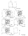
- Fig. 4 is a flow diagram schematically illustrating a film formation process in which the film forming apparatus shown in Fig. 1 is used.
- the film forming apparatus 100 in Fig. 4 is illustrated by simplifying the sectional view of Fig. 3.
- the substrate W is molded by the dies P, P'.
- the die joint faces of the dies P, P' are separated from each other as illustrated in Fig. 4(b).
- the substrate W is left in the die P with its film forming face W exposed.
- the valve body 4a is actuated by the actuator (not shown) through a specified operation to close the through hole 4c, so that the preliminary closed space A is formed by the valve body 4a, the inner holes 2c, 3c, the through hole 4c and the apparatus section 1.
- a pipe (not shown) is connected to a known vacuum pump (not shown).
- the preliminary closed space A is brought into a vacuum condition under a specified pressure by this vacuum pump.
- Pipes are connected to the coolant pipe connection portions 1d respectively from outside and a coolant flows in the coolant passages 1p, 1c.
- All the pipe connection portions 3b are not necessarily connected to a vacuum pump and some of them may be connected to a known gas feeder through a shut-off valve, for the purpose of feeding discharge gas such as argon gas and reactive gas such as methane gas.
- either the die P or the film forming apparatus 100 or both of them are moved, thereby joining the second face 5f of the adaptor section 5 of the film forming apparatus 100 to the die joint face Pa of the die P.
- Joining of the die joint face Pa to the film forming apparatus 100 is done such that the film forming face Wa of the substrate W is opposed to the through hole 5c; the whole circumference of the O-ring 5b is joined to the mold joint face Pa; and the contact-proof portion 5a is brought into contact with a specified position of the substrate W (so as to cover the specified position).
- the film forming apparatus 100 is supported by a supporting structural member (not shown) such as a machine casing and a joining force is applied to the film forming apparatus 100 from its rear side.
- a supporting structural member such as a machine casing
- a joining force is applied to the film forming apparatus 100 from its rear side.
- the film forming apparatus 100 since voltage for sputtering is applied to the apparatus section 1, the film forming apparatus 100 needs to be supported at other parts than the apparatus section 1.
- the film forming apparatus 100 may be supported at the adaptor section 5.
- the valve body 4a is retracted from the through hole 4c, being actuated by the actuator (not shown) through a specified operation, so that the closed space B is formed by the film forming face Wa, the contact-proof portion 5a, the through holes 5c, 4c, the inner holes 3c, 2c and the apparatus section 1.
- air is evacuated by the vacuum pumps through the ports 3a and the pipe connection portions 3b, so that the closed space B is brought into a highly vacuum condition. Since the preliminary closed space A is brought into the vacuum condition beforehand, vacuuming after releasing the valve body 4a can be performed in a short time.
- the 0-ring 5b is inserted between the die joint face Pa and the adaptor section 5 thereby to prevent an inflow of outside air.
- a specified voltage is applied to the target 1a (more particularly, between the electric connection terminal 1f and the port section 3) and the film forming material which has been sputtered from the target 1a and moved to the closed space B. Then, the forming material is deposited on the film forming face Wa of the substrate W, thus forming a film over the film forming face Wa.
- the closed space B functions as a vacuum chamber. Since the substrate W and other elements than the apparatus section 1 are electrically insulated from the apparatus section 1 by the insulating spacer 2 and the insulating guide 11, a potential difference can be caused between the target 1a and the other elements than the apparatus section 1/the substrate W by applying voltage to the electric connection terminal 1f of the apparatus section 1.
- the magnet 1b is disposed behind the target 1a and therefore magnetron sputtering is carried out.
- This film formation process is similar to the process performed by the known film forming apparatus. It should be noted that discharge gas and/or reactive gas may be introduced through some of the ports 3a.
- valve body 4a is actuated by the actuator through a specified operation to close the through hole 4c. Thereby, the vacuum condition of the preliminary closed space A can be maintained.
- the substrate W having a film formed thercon is removed from the die P as illustrated in Fig. 4(g).
- various vacuum film formation techniques may be applied to the invention. Since the invention can utilize the closed space B as a vacuum chamber, use of various vacuum film formation techniques may be applied by changing the arrangement of the devices disposed in the wall face of the closed space B opposed to the film forming face Wa of the substrate W, such as the mounting position of the target 1a.
- a second embodiment of the invention is associated with a film forming apparatus 110 that exemplifies apparatus which do not use the gate valve section 4 of the first embodiment.
- Fig. 5 is a sectional view taken along the same line as in Fig. 3, which illustrates a joining structure of the film forming apparatus 110, the die P and the substrate W.
- the film forming apparatus 110 is composed of the apparatus section 1, the insulating spacer 2, a port section 13 and the adaptor section 5 which are integrally joined in order by means of the bolts 7, 9.
- the film forming apparatus 110 does not differ from the film forming apparatus 100 of the first embodiment except that the apparatus 110 is not provided with the gate valve section 4, and that the apparatus 110 is not provided with the port section 13 which differs in shape from the port section 3.
- the port section 13 is formed such that a second end face 13f is joined to the first face 5e of the adaptor section 5. Threaded holes 13k are so formed in the second end face 13f as to correspond to the bolt insertion holes 5k.
- the extending portion that inwardly extends from the second end face 13f is thicker than the extending portion that inwardly extends from the second end face 3f of the first embodiment.
- the adaptor section 5 is integrally fastened to the port section 13 by the bolts 7 such that the through hole 5c and the inner hole 13c of the port section 13 have the central axis 50 as their common axis and such that the first face 5e is joined to the second end face 13f of the port section 13.
- the bolts 7 are screwed into and stopped at their associated threaded holes 13k, after passing through their associated bolt insertion holes 5k.
- the operation of the film forming apparatus 110 of the second embodiment having the above structure does not differ from that of the film forming apparatus 100 of the first embodiment except that the former does not involve the operation of the gate valve section 4.
- a closed space C formed by the film forming face Wa, the contact-proof portion 5a, the through hole 5c, the inner hole 13c, the inner hole 2c and the apparatus section 1 is vacuumed through ports 13a and pipe connection portions 13b.
- Fig. 6 is a piping diagram showing one example of the schematic construction of an exhaust system 200 connected to the film forming apparatus 110 shown in Fig. 5.
- the exhaust system 200 is composed of pipes 27, 22, 23, vacuum pumps P1, P2, a depressurization chamber 24 and valves V1, V2, V3.
- the pipe 21 is connected to the pipe connection portion 13b at one end and to first ends of the pipes 22, 23 at the other end.
- a second end of the pipe 22 is connected to a suction port of the second vacuum pump P2.
- the pipe 22 is provided with a valve V2, a depressurization chamber 24, a first vacuum pump P1 and a valve V3 which are aligned in this order when viewed from the first end.
- the suction port of the first vacuum pump P1 is connected to the depressurization chamber 24.
- the pipe 23 has a valve V1 disposed in the middle thereof and is connected, at the second end, to the suction port of the second vacuum pump P2.
- valves V1, V2 are first closed and then, the valve V3 is opened. Subsequently, the first vacuum pump P1 and the second vacuum pump P2 are operated. A part of the pipe 22 situated between the valve V2 and the vacuum pump P1. as well as the depressurization chamber 24 is brought into a highly vacuum condition. A part of the pipe 22 situated between the vacuum pump P1 and the vacuum pump P2 and a part of the pipe 23 situated between the valve V1 and the vacuum pump P2 are brought into a vacuum condition.
- valve V3 is closed and the valve V1 is opened.
- the valve V1 is closed whereas the valve V2 is opened so that the closed space C is allowed to communicate with the depressurization chamber 24. Thereby, the time required for vacuuming the closed space C can be reduced.
- the invention enables it to apply film formation to a substrate which is left in a molding die without being removed therefrom after molding forming, the invention is useful as a film forming apparatus capable of reducing the number of steps of processing a product and, in consequence, the time required for processing the product.
Landscapes
- Chemical & Material Sciences (AREA)
- Engineering & Computer Science (AREA)
- Physics & Mathematics (AREA)
- Plasma & Fusion (AREA)
- Analytical Chemistry (AREA)
- Chemical Kinetics & Catalysis (AREA)
- Materials Engineering (AREA)
- Mechanical Engineering (AREA)
- Metallurgy (AREA)
- Organic Chemistry (AREA)
- Physical Vapour Deposition (AREA)
- Moulds For Moulding Plastics Or The Like (AREA)
Abstract


Description
- The present invention relates to a film forming apparatus, and more particularly, to a film forming apparatus capable of performing film formation on a substrate that is left in a die without being removed therefrom after molding forming.
- Conventionally, film formation processing is done with a substrate mounted on a carrier for use in a film forming apparatus or a film forming apparatus itself. Therefore, a substrate for e.g., a lamp reflector for automobiles etc. is removed from the dies after molding forming and then mounted on a film forming apparatus or the like to form a film on it.
- As described above, the conventional film forming apparatus require, after molding forming, the preparatory steps of removing the substrate from the dies and mounting it on the film forming apparatus or the like.
- A primary object of the invention is to provide a film forming apparatus capable of obviating the need for the preparatory steps, i.e., the removal of a substrate from the dies and mounting of it on the film forming apparatus or the like, by performing film formation on a substrate left in a molding die, thereby reducing the number of steps of processing a product and, in consequence, the processing time and cost of the product.
- The above object can be accomplished by a film forming apparatus according to the invention, the apparatus comprising:
- a cylindrical frame one end of which is closed by a bottom part while the other end is opened;
- a target disposed on an inner surface of the bottom part; and
- a port formed so as to penetrate a wall portion of the frame (claim 1). With this arrangement, film formation processing can be performed on a substrate mounted on a die, so that the number of steps of processing a product and, in consequence, the processing time and cost of the product can be reduced.
- The target may be disposed so as to be electrically insulated from the wall portion (claim 2).
- The bottom part may be electrically conductive (claim 3). This enables potential application to the target through the bottom part, so that the electric system of the film forming apparatus can be simplified.
- An electric connection terminal may be disposed at an outer surface of the bottom part (claim 4).
- A gate valve may be disposed in the wall portion so as to open and close a communication between the opened end of the frame and the target (claim 5). This enables it to form a preliminary closed space surrounding the main face of the target, so that the time required for vacuuming can be reduced and the target can be protected.
- The film forming apparatus may further comprise:
- an apparatus section in which the target is placed at its front face and the electric connection terminal is placed at its rear face;
- a cylindrical port section in which the port is formed so as to penetrate the wall portion;
- an annular electrically insulating spacer;
- a gate valve section having a frame in which a through hole provided with an opening/closing gate valve is formed; and
- an adaptor section having a frame provided with a through hole and a joint face that is formed on an outer surface of the frame in relation to a joint face of a die, the outer surface surrounding the through hole;
- wherein a rear end of the port section is joined through the insulating spacer to a periphery of the target situated at the front face of the apparatus section, and the gate valve section and the adaptor section are joined to a front end of the port section in order,
- wherein an inner hole of the insulating spacer, an inner hole of the port section, the through hole of the gate valve section and the through hole of the adaptor section communicate with one another, and the joint face of the adaptor section is located at a front end of the film forming apparatus, the joint face being formed so as to be joinable to the die joint face that surrounds a substrate left in the die (claim 6).
- The apparatus section may include a magnet and a cooling system which are located behind the target (claim 7). With this arrangement, magnetron sputtering can be carried out.
- A contact-proof portion may be formed on the outer surface of the frame surrounding the through hole of the adaptor section, for covering a specified part of the substrate when the joint face of the adaptor section comes into contact with the die joint face that surrounds the substrate left in the die (claim 8). This makes it possible to exclude the specified part from the area subjected to film formation.
- A piping having a valve, a depressurization chamber and a vacuum pump is connected to the port, and this piping is so formed as to selectively change connection between the vacuum pump and the depressurization chamber (claim 9). In this arrangement, the depressurization chamber enables a reduction in the time required for vacuuming.
- As described earlier, the invention has such an effect that since film formation processing can be performed on a substrate that is left on a molding die without being removed therefrom after molding forming, the number of steps of processing a product and, therefore, the processing time and cost for the product can be reduced.
-
- [Fig. 1] Fig. 1 is views schematically illustrating a film forming apparatus according to a first embodiment of the invention, wherein Figs. 1(a), 1(b), 1(c) are a front view, side view and rear view, respectively.
- [Fig. 2] Fig. 2 is an exploded perspective view illustrating a connecting structure of the film forming apparatus shown in Fig. 1.
- [Fig. 3] Fig. 3 is a sectional view taken along line III-III of Fig. 1, which illustrates a joining structure of the film forming apparatus, a die and a substrate.
- [Fig. 4] Fig. 4 is a flow diagram schematically illustrating a film formation process in which the film forming apparatus shown in Fig. 1 is used.
- [Fig. 5] Fig. 5 is a sectional view taken along the same line as in Fig. 3, which illustrates a joining structure of a film forming apparatus according to a second embodiment of the invention, a die and a substrate.
- [Fig. 6] Fig. 6 is a piping diagram showing one example of the schematic construction of an exhaust system connected to the film forming apparatus shown in Fig. 5.
-
- 1:
- apparatus section
- 1a:
- target
- 1b:
- magnet
- 1c, 1p:
- coolant passage
- 1d:
- coolant pipe connection portion
- 1e:
- joint face
- 1f:
- electric connection terminal
- 1g:
- bolt insertion hole
- 1h:
- frame
- 2:
- insulating spacer
- 2c:
- inner hole
- 2g:
- bolt insertion hole
- 3:
- port section
- 3a:
- port
- 3b:
- pipe connection portion
- 3c;
- inner hole
- 3e:
- first end face
- 3f:
- second end face
- 3g:
- threaded hole
- 3j:
- bolt insertion hole
- 4;
- gate valve section
- 4a:
- valve body
- 4b:
- valve body movement space
- 4c:
- through hole
- 4e; 4f:
- joint face
- 4j:
- threaded hole
- 4k:
- threaded hole
- 4n, 4m:
- boss portion
- 5:
- adaptor section
- 5a:
- contact-proof portion
- 5b:
- 0-ring
- 5c:
- through hole
- 5e:
- first face
- 5f:
- end face on the opened side (second face)
- 5k:
- bolt insertion hole
- 7, 8, 9:
- bolt
- 11:
- insulating guide
- 13:
- port section
- 13a:
- port
- 13b:
- pipe connection portion
- 13c:
- inner hole
- 13e:
- first end face
- 13f:
- second end face
- 13k:
- threaded hole
- 15:
- recess portion
- 15a:
- stepped portion
- 21, 22, 23:
- pipe
- 24:
- depressurization chamber
- 50:
- central axis
- 61:
- molding cavity
- 100, 110:
- film forming apparatus
- 200:
- exhaust system
- A:
- preliminary closed space
- B:
- closed space
- C:
- closed space
- V1, V2, V3:
- valve
- P1:
- first vacuum pump
- P2:
- second vacuum pump
- W:
- substrate
- Wa:
- film forming face
- P:
- die
- Pa:
- die joint face
- P':
- die
- Referring now to the accompanying drawings, the best mode for carrying out the invention will be described.
- Fig. 1 is views schematically illustrating a
film forming apparatus 100 according to a first embodiment of the invention, wherein Figs. 1(a), 1(b), 1(c) are a front view, side view and rear view, respectively. Fig. 2 is an exploded perspective view illustrating a connecting structure of thefilm forming apparatus 100 shown in Fig. 1. Fig. 3 is a sectional view taken along line III-III of Fig. 1, which illustrates a joining structure of thefilm forming apparatus 100, a die P and a substrate W. It should be noted that Fig. 3 shows only somescrews guide 11 and omits their identical screws etc. - First of all, the whole structure will be described. As shown in Figs. 1 to 3, the
film forming apparatus 100 is formed in the shape of a cylinder, on the whole, that is closed by a bottom part (i.e., apparatus section 1) at an end thereof and opened at the other end thereof. Atarget 1a is disposed at the inner surface of the bottom part and an annular joint face is formed at anend face 5f on the opened side. As described later, in the cylindricalfilm forming apparatus 100, thetarget 1a is formed so as to be electrically insulated from a wall face defining aninner hole 2c, a wall face defining aninner hole 3c, a wall face defining a throughhole 4c, a wall face defining a throughhole 5c and theend face 5f on the opened side. Thefilm forming apparatus 100 has one or a plurality ofports 3a that make a closed space B communicate with the outside of thefilm forming apparatus 100. - The
film forming apparatus 100 is made up of separated parts, i.e., theapparatus section 1, an insulatingspacer 2, aport section 3, agate valve section 4, and anadaptor section 5. These parts are integrated, being fastened to one another by means ofbolts target 1a of theapparatus section 1, theinner hole 2c of thespacer 2, theinner hole 3c of theport section 3, the throughhole 4c of thegate valve section 4 and the throughhole 5c of theadaptor section 5 have a commoncentral axis 50. Thereby, the closed space B is formed in the shape of a column which bottom face is defined by thetarget 1a. Further, these members are integrated with seal members (not shown) such as O-rings interposed between their joint faces, so that the closed space B has an air tight structure. - The structure of each member will be hereinafter described in detail. In the following description, the direction from the
apparatus section 1 toward theadaptor section 5 is defined as "forward direction". - The
apparatus section 1 has aframe 1h made of a rigid material. As illustrated in Fig. 3, theframe 1h takes the form of a stepped cylinder in which a small diameter portion projects from the front end face of a large diameter portion and the small and large diameter portions have thecentral axis 50 as their common axis. Thetarget 1a is disposed at the front end face of the small diameter portion. Specifically, arecess portion 15 having a steppedportion 15a is formed at the front end face of the small diameter portion and thetarget 1a is liquid-tightly disposed in the steppedportion 15a. At the rear face of thetarget 1a, amagnet 1b is placed, with a gap (coolant passage 1c) between themagnet 1b and the inner surface of therecess portion 15. A pair ofcoolant passages 1p extend from the bottom face of therecess portion 15 to the rear end face of the large diameter portion. A pair of coolantpipe connection portions 1d are provided in the openings of the pair ofcoolant passages 1p respectively so as to project from the rear end face of the large diameter portion, that is, the rear face of theapparatus section 1. One of the coolantpipe connection portions 1d is an inlet for the coolant whereas the other is an outlet for the coolant. Thereby, a path for a coolant is so established that the coolant enters from one of the coolantpipe connection portions 1d and flows out from the other coolantpipe connection portion 1d after flowing in one of thecoolant passages 1p, thecoolant passage 1c and the othercoolant pipe passage 1p in order. As a result, thetarget 1a and themagnet 1b can be cooled. - The stepped portion of the
apparatus section 1 constitutes a joint face 1e. Formed at the joint face 1e are a plurality ofbolt insertion holes 1g that pass through the large diameter portion. - Projectingly formed at the rear face of the
frame 1h is anelectric connection terminal 1f that is electrically connected to thetarget 1a. Herein, theframe 1h is made of a metal having high electric conductivity, so that theelectric connection terminal 1f and thetarget 1a are electrically connected to each other. - The
port section 3 is cylindrical in shape. Afirst end face 3e, which is the rear end face of theport section 3, has an annular shape joinable to the joint face 1e of theapparatus section 1. More specifically, thefirst end face 3e has substantially the same outer diameter as of the large diameter portion of theapparatus section 1 and larger inner diameter (the diameter of theinner hole 3c) than the small diameter portion of theapparatus section 1. In thefirst end face 3e, threadedholes 3g are so formed as to correspond to thebolt insertion holes 1g of theapparatus section 1. Theports 3a are so formed as to pierce the wall portion of theport section 3. While threeports 3a are formed herein, being aligned in a circumferential direction, one or a plurality ofports 3a may be used.Pipe connection portions 3b are provided in the openings of theports 3a that pass through the outer circumferential face of theport section 3. The wall portion of theport section 3 includes an extending portion that inwardly extends from the front end of theport section 3, and a plurality ofbolt insertion holes 3j are so formed as to penetrate this extending portion. - The insulating
spacer 2 is in the form of a hollow disk having substantially the same outer diameter and inner diameter (the diameter of theinner hole 2c) as of thefirst end face 3e of theport section 3. Formed in the insulatingspacer 2 arebolt insertion holes 2g that correspond to thebolt insertion holes 1g of theapparatus section 1. The insulatingspacer 2 is made of an electrically insulating elastic material such as a rubber packing, in order to electrically insulate and seal between the joint face 1e of theapparatus section 1 and thefirst end face 3e of theport section 3. - Now, the connecting structure of the
apparatus section 1, the insulatingspacer 2 and theport section 3 will be explained. Theapparatus section 1 and theport section 3 are integrally fastened to each other bybolts 9 with the insulatingspacer 2 being interposed between the joint face 1e and thefirst end face 3e. Thereby, theapparatus section 1 and theport section 3 are not in direct contact with each other but arranged such that the insulatingspacer 2 is present in all the spaces between the joint face 1e and thefirst end face 3e which are opposed to each other. For fastening thesesections bolts 9, electrically insulatingguides 11 in the form of a cylinder having a collar are used. Specifically, each insulatingguide 11 is inserted into thebolt insertion holes bolt 9 is screwed into and stopped at a threadedhole 3g of theport section 3, after passing through the insulatingguide 11. This prevents electrical continuity between theapparatus section 1 and theport section 3 through thebolts 9. - The entire
gate valve section 4 is the form of a rectangular plate having a throughhole 4c at the center thereof. Formed in thegate valve section 4 is a plate-shaped valvebody movement space 4b that traverses the throughhole 4c. In the valvebody movement space 4b, a plate-shapedvalve body 4a is accommodated so as to be slidable in the valvebody movement space 4b, thereby opening and closing the throughhole 4c. Thevalve body 4a is connected to an actuator (not shown) such as a piston rod for air cylinders and is slidingly actuated by this actuator, thereby opening and closing the throughhole 4c. The sliding part between the actuator and the gate valve section is properly sealed so that the valvebody movement space 4b is kept hermetic relative to the outside and therefore outside air does not penetrate when thevalve body 4a is in sliding movement. The throughhole 4c is formed so as to have a larger cross-sectional area than a film forming face Wa of a substrateW. Boss portions hole 4c, respectively. The end faces of theboss portions joint faces joint face 4e, threadedholes 4j are formed so as to correspond to thebolt insertion holes 3j of theport section 3. In thejoint face 4f, threadedholes 4k are formed. Concretely, thegate valve section 4 of the first embodiment is constituted by the known gate valve (high-vacuum gate valve (with a protect ring) produced by VAT SKK VACUUM Ltd.) for use in vacuum equipment. - The
gate valve section 4 is integrally fastened to theport section 3 bybolts 8 such that the throughhole 4c and theinner hole 3c have thecentral axis 50 as their common axis and thejoint face 4e is joined to a secondjoint face 3f of theport section 3. Eachbolt 8 is screwed into and stopped at a threadedhole 4j of thegate valve section 4, after passing through thebolt insertion hole 3j of theport section 3. The joint part where thesecond end face 3f of theport section 3 and thejoint face 4e of thegate valve section 4 are joined is sealed by a sealing member (not shown). - Herein, the
adaptor section 5 is formed in the shape of a square plate and has the throughhole 5c formed at the center thereof. Afirst face 5e, which is the rear face of theadaptor section 5, constitutes a joint face joined to ajoint face 4f of thegate valve section 4. In addition, thesecond face 5f, which is the front face of theadaptor section 5, constitutes a joint face to be joined to a joint face Pa of a die P. Thesecond face 5f has an annular contact-proof portion 5a that surrounds the opening of the throughhole 5c. - The joint face Pa of the die P is provided with a
molding cavity 61 in which the substrate W is molded. The opening of the throughhole 5c of theadaptor section 5 is formed such that when theadaptor section 5 is joined to the die P, the surface Wa (hereinafter referred to as "film forming face") of the substrate W on which a film is to be formed is exposed to the throughhole 5c (i.e., the closed space B of the film forming apparatus 100). Specifically, the wall face defining the throughhole 5c is formed so as to coincide with the outer periphery of the film forming face Wa such that film formation does not take place in the die joint face Pa. Since the outer periphery of the film forming face Wa includes a face which should not be filmed (hereinafter referred to as "non-filmed face") in some cases depending on the substrate W required, the annular contact-proof portion 5a is provided on the rim of the throughhole 5c of theadaptor section 5 so as to come into contact with the non-filmed face of the substrate W to cover it when theadaptor section 5 is joined to the die P. One example of the non-filmed face of the substrate W is the joint faces of a substrate that is joined to other parts. In molding the substrate W, the outer periphery of the substrate W is sometimes formed in a position anterior to the die joint face Pa (based on the drawings), that is, a position set back from the die joint face Pa. Therefore, the contact-proof portion 5a is convex in shape. - The
second face 5f of theadaptor section 5 is provided with spot facings (concave portions) that are located at positions corresponding to the threadedholes 4k of thegate valve section 4, for accommodating the heads ofbolts 7. Each of these spot facings is formed abolt insertion hole 5k. In addition, thesecond face 5f is provided with an O-ring 5b that is formed so as to surround the contact-proof portion 5a. - The
adaptor section 5 is integrally fastened to thegate valve section 4 by thebolts 7 such that the throughhole 5c and the throughhole 4c of thegate valve section 4 have thecentral axis 50 as their common axis and thejoint face 5e is joined to thejoint face 4f of thegate valve section 4. Thebolts 7 are screwed into and stopped at their associated threadedholes 4k of thegate valve section 4, after passing through their associated bolt insertion holes 5k of theadaptor section 5. The heads of thebolts 7 are housed in the spot facings of thebolt insertion holes 5k, and therefore, the heads of thebolts 7 are prevented from coming into contact with the die P when the die P is joined to theadaptor section 5. Additionally, the joint part where thefirst face 5e of theadaptor section 5 and thejoint face 4f of thegate valve section 4 are joined is sealed by a sealing member (not shown). - Thus, the
film forming apparatus 100 is constructed by joining theapparatus section 1, the insulatingspacer 2. theport section 3, thegate valve section 4 and theadaptor section 5 in order. - Next, the operation of the
film forming apparatus 100 having the above structure will be described. - Fig. 4 is a flow diagram schematically illustrating a film formation process in which the film forming apparatus shown in Fig. 1 is used. The
film forming apparatus 100 in Fig. 4 is illustrated by simplifying the sectional view of Fig. 3. - As illustrated in Fig. 4(a), the substrate W is molded by the dies P, P'.
- After the molding, the die joint faces of the dies P, P' are separated from each other as illustrated in Fig. 4(b). The substrate W is left in the die P with its film forming face W exposed.
- In the
film forming apparatus 100, thevalve body 4a is actuated by the actuator (not shown) through a specified operation to close the throughhole 4c, so that the preliminary closed space A is formed by thevalve body 4a, theinner holes hole 4c and theapparatus section 1. In thepipe connection portion 3b, a pipe (not shown) is connected to a known vacuum pump (not shown). The preliminary closed space A is brought into a vacuum condition under a specified pressure by this vacuum pump. By making the space A vacuum beforehand, the time required for vacuuming after joining thefilm forming apparatus 100 to the substrate W can be reduced. In addition, damage to thetarget 1a and, particularly, oxidation can be prevented by bringing thegate valve section 4 into a closed state and placing thetarget 1 in vacuum atmosphere. - Pipes are connected to the coolant
pipe connection portions 1d respectively from outside and a coolant flows in thecoolant passages - All the
pipe connection portions 3b are not necessarily connected to a vacuum pump and some of them may be connected to a known gas feeder through a shut-off valve, for the purpose of feeding discharge gas such as argon gas and reactive gas such as methane gas. - As illustrated in Fig. 4(c), either the die P or the
film forming apparatus 100 or both of them are moved, thereby joining thesecond face 5f of theadaptor section 5 of thefilm forming apparatus 100 to the die joint face Pa of the die P. Joining of the die joint face Pa to thefilm forming apparatus 100 is done such that the film forming face Wa of the substrate W is opposed to the throughhole 5c; the whole circumference of the O-ring 5b is joined to the mold joint face Pa; and the contact-proof portion 5a is brought into contact with a specified position of the substrate W (so as to cover the specified position). Herein, thefilm forming apparatus 100 is supported by a supporting structural member (not shown) such as a machine casing and a joining force is applied to thefilm forming apparatus 100 from its rear side. In this supporting mechanism, since voltage for sputtering is applied to theapparatus section 1, thefilm forming apparatus 100 needs to be supported at other parts than theapparatus section 1. For example, thefilm forming apparatus 100 may be supported at theadaptor section 5. - As illustrated in Fig. 4(d), the
valve body 4a is retracted from the throughhole 4c, being actuated by the actuator (not shown) through a specified operation, so that the closed space B is formed by the film forming face Wa, the contact-proof portion 5a, the throughholes inner holes apparatus section 1. Then, air is evacuated by the vacuum pumps through theports 3a and thepipe connection portions 3b, so that the closed space B is brought into a highly vacuum condition. Since the preliminary closed space A is brought into the vacuum condition beforehand, vacuuming after releasing thevalve body 4a can be performed in a short time. The 0-ring 5b is inserted between the die joint face Pa and theadaptor section 5 thereby to prevent an inflow of outside air. - A specified voltage is applied to the
target 1a (more particularly, between theelectric connection terminal 1f and the port section 3) and the film forming material which has been sputtered from thetarget 1a and moved to the closed space B. Then, the forming material is deposited on the film forming face Wa of the substrate W, thus forming a film over the film forming face Wa. In short, the closed space B functions as a vacuum chamber. Since the substrate W and other elements than theapparatus section 1 are electrically insulated from theapparatus section 1 by the insulatingspacer 2 and the insulatingguide 11, a potential difference can be caused between thetarget 1a and the other elements than theapparatus section 1/the substrate W by applying voltage to theelectric connection terminal 1f of theapparatus section 1. Herein, themagnet 1b is disposed behind thetarget 1a and therefore magnetron sputtering is carried out. - This film formation process is similar to the process performed by the known film forming apparatus. It should be noted that discharge gas and/or reactive gas may be introduced through some of the
ports 3a. - As illustrated in Fig. 4(e), after completion of the film formation, the
valve body 4a is actuated by the actuator through a specified operation to close the throughhole 4c. Thereby, the vacuum condition of the preliminary closed space A can be maintained. - Then, the die P and the
film forming apparatus 100 are separated from each other as illustrated in Fig. 4(f). - Subsequently, the substrate W having a film formed thercon is removed from the die P as illustrated in Fig. 4(g).
- While the above description is associated with a case where magnetron sputtering is used, various vacuum film formation techniques may be applied to the invention. Since the invention can utilize the closed space B as a vacuum chamber, use of various vacuum film formation techniques may be applied by changing the arrangement of the devices disposed in the wall face of the closed space B opposed to the film forming face Wa of the substrate W, such as the mounting position of the
target 1a. - A second embodiment of the invention is associated with a
film forming apparatus 110 that exemplifies apparatus which do not use thegate valve section 4 of the first embodiment. - Fig. 5 is a sectional view taken along the same line as in Fig. 3, which illustrates a joining structure of the
film forming apparatus 110, the die P and the substrate W. - The
film forming apparatus 110 is composed of theapparatus section 1, the insulatingspacer 2, aport section 13 and theadaptor section 5 which are integrally joined in order by means of thebolts film forming apparatus 110 does not differ from thefilm forming apparatus 100 of the first embodiment except that theapparatus 110 is not provided with thegate valve section 4, and that theapparatus 110 is not provided with theport section 13 which differs in shape from theport section 3. - Herein, the
port section 13 is formed such that asecond end face 13f is joined to thefirst face 5e of theadaptor section 5. Threadedholes 13k are so formed in thesecond end face 13f as to correspond to thebolt insertion holes 5k. The extending portion that inwardly extends from thesecond end face 13f is thicker than the extending portion that inwardly extends from thesecond end face 3f of the first embodiment. - Other elements are the same as those of the
film forming apparatus 100 and therefore an explanation of them will be skipped. - The
adaptor section 5 is integrally fastened to theport section 13 by thebolts 7 such that the throughhole 5c and theinner hole 13c of theport section 13 have thecentral axis 50 as their common axis and such that thefirst face 5e is joined to thesecond end face 13f of theport section 13. Thebolts 7 are screwed into and stopped at their associated threadedholes 13k, after passing through their associatedbolt insertion holes 5k. - The joint part where the
first face 5e and thesecond end face 13f are joined is properly sealed. - The operation of the
film forming apparatus 110 of the second embodiment having the above structure does not differ from that of thefilm forming apparatus 100 of the first embodiment except that the former does not involve the operation of thegate valve section 4. - In the
film forming apparatus 110, after joining thefilm forming apparatus 110 to the die P, a closed space C formed by the film forming face Wa, the contact-proof portion 5a, the throughhole 5c, theinner hole 13c, theinner hole 2c and theapparatus section 1 is vacuumed throughports 13a andpipe connection portions 13b. - Fig. 6 is a piping diagram showing one example of the schematic construction of an
exhaust system 200 connected to thefilm forming apparatus 110 shown in Fig. 5. - The
exhaust system 200 is composed ofpipes depressurization chamber 24 and valves V1, V2, V3. - The
pipe 21 is connected to thepipe connection portion 13b at one end and to first ends of thepipes - A second end of the
pipe 22 is connected to a suction port of the second vacuum pump P2. Thepipe 22 is provided with a valve V2, adepressurization chamber 24, a first vacuum pump P1 and a valve V3 which are aligned in this order when viewed from the first end. The suction port of the first vacuum pump P1 is connected to thedepressurization chamber 24. - The
pipe 23 has a valve V1 disposed in the middle thereof and is connected, at the second end, to the suction port of the second vacuum pump P2. - The operation of the
exhaust system 200 having the above structure will be explained. - In Fig. 6, the valves V1, V2 are first closed and then, the valve V3 is opened. Subsequently, the first vacuum pump P1 and the second vacuum pump P2 are operated. A part of the
pipe 22 situated between the valve V2 and the vacuum pump P1. as well as thedepressurization chamber 24 is brought into a highly vacuum condition. A part of thepipe 22 situated between the vacuum pump P1 and the vacuum pump P2 and a part of thepipe 23 situated between the valve V1 and the vacuum pump P2 are brought into a vacuum condition. - Thereafter, the valve V3 is closed and the valve V1 is opened. After the degree of vacuum of the closed space C has reached a certain value, the valve V1 is closed whereas the valve V2 is opened so that the closed space C is allowed to communicate with the
depressurization chamber 24. Thereby, the time required for vacuuming the closed space C can be reduced. - Since the invention enables it to apply film formation to a substrate which is left in a molding die without being removed therefrom after molding forming, the invention is useful as a film forming apparatus capable of reducing the number of steps of processing a product and, in consequence, the time required for processing the product.
Claims (9)
- A film forming apparatus comprising:a cylindrical frame one end of which is closed by a bottom part while the other end is opened;a target disposed on an inner surface of the bottom part; anda port formed so as to penetrate a wall portion of the frame.
- The film forming apparatus according to claim 1,
wherein said target is disposed so as to be electrically insulated from the wall portion. - The film forming apparatus according to claim 2,
wherein said bottom part is electrically conductive. - The film forming apparatus according to claim 3, further comprising:an electric connection terminal disposed at an outer surface of the bottom part.
- The film forming apparatus according to claim 1,
wherein a gate valve is disposed in the wall portion so as to open and close a communication between the opened end of said frame and said target. - The film forming apparatus according to claim 5, further comprising:an apparatus section in which said target is placed at its front face and said electric connection terminal is placed at its rear face;a cylindrical port section in which said port is formed so as to penetrate the wall portion;an annular electrically insulating spacer;a gate valve section having a frame in which a through hole provided with an opening/closing gate valve is formed; andan adaptor section having a frame provided with a through hole and a joint face that is formed on an outer surface of the frame in relation to a joint face of a die, the outer surface surrounding the through hole;wherein a rear end of said port section is joined through said insulating spacer to a periphery of said target situated at the front face of the apparatus section, and said gate valve section and said adaptor section are joined to a front end of said port section in order,wherein an inner hole of said insulating spacer, an inner hole of said port section, the through hole of said gate valve section and the through hole of said adaptor section communicate with one another, and the joint face of said adaptor section is located at a front end of the film forming apparatus, the joint face being formed so as to be joinable to the die joint face that surrounds a substrate left in the die.
- The film forming apparatus according to claim 6,
wherein said apparatus section includes a magnet and a cooling system which are located behind said target. - The film forming apparatus according to claim 6,
wherein a contact-proof portion is formed on the outer face of the frame surrounding the through hole of said adaptor section, for covering a specified part of the substrate when the joint face of said adaptor section comes into contact with the die joint face that surrounds the substrate left in the die. - The film forming apparatus according to claim 1,
wherein a piping having a valve, a depressurization chamber and a vacuum pump is connected to said port, and
wherein said piping is so formed as to selectively change connection between the vacuum pump and the depressurization chamber.
Applications Claiming Priority (2)
| Application Number | Priority Date | Filing Date | Title |
|---|---|---|---|
| JP2004070524A JP4393897B2 (en) | 2004-03-12 | 2004-03-12 | Deposition equipment |
| PCT/JP2005/004216 WO2005087972A1 (en) | 2004-03-12 | 2005-03-10 | Film forming apparatus |
Publications (2)
| Publication Number | Publication Date |
|---|---|
| EP1752558A1 true EP1752558A1 (en) | 2007-02-14 |
| EP1752558A4 EP1752558A4 (en) | 2008-07-30 |
Family
ID=34975609
Family Applications (1)
| Application Number | Title | Priority Date | Filing Date |
|---|---|---|---|
| EP05720487A Withdrawn EP1752558A4 (en) | 2004-03-12 | 2005-03-10 | FILMING EQUIPMENT |
Country Status (7)
| Country | Link |
|---|---|
| US (1) | US20070277732A1 (en) |
| EP (1) | EP1752558A4 (en) |
| JP (1) | JP4393897B2 (en) |
| KR (1) | KR101131313B1 (en) |
| CN (1) | CN100529166C (en) |
| TW (1) | TW200532042A (en) |
| WO (1) | WO2005087972A1 (en) |
Families Citing this family (3)
| Publication number | Priority date | Publication date | Assignee | Title |
|---|---|---|---|---|
| JP2007112119A (en) * | 2005-09-22 | 2007-05-10 | Igari Mold Kk | Mold assembly for molding blow molded product and molding method of blow molded product |
| CN104637766B (en) * | 2013-11-14 | 2017-02-08 | 中微半导体设备(上海)有限公司 | Reaction cavity structure and semiconductor plasma processing system |
| CN119243112A (en) * | 2024-10-14 | 2025-01-03 | 江苏微导纳米科技股份有限公司 | Film forming equipment |
Family Cites Families (13)
| Publication number | Priority date | Publication date | Assignee | Title |
|---|---|---|---|---|
| US2635289A (en) * | 1945-11-16 | 1953-04-21 | Freeman H Owens | Method and means for producing optical and other precision elements and the products thereof |
| CA1104712A (en) * | 1978-09-08 | 1981-07-07 | Robert Milne | Broadband shaped beam antenna |
| JPS6454733A (en) | 1987-08-26 | 1989-03-02 | Toshiba Corp | Production device for semiconductor |
| US5135629A (en) * | 1989-06-12 | 1992-08-04 | Nippon Mining Co., Ltd. | Thin film deposition system |
| JPH0489546U (en) * | 1990-12-12 | 1992-08-05 | ||
| EP0686211A4 (en) * | 1993-02-19 | 1997-09-17 | Conner Peripherals Inc | SYSTEM FOR CATHODE SPRAYING OF COMPOSITIONS ON A SUBSTRATE |
| JPH07258839A (en) | 1994-03-18 | 1995-10-09 | Hitachi Ltd | Sputtering equipment |
| JPH0931642A (en) | 1995-07-20 | 1997-02-04 | Hitachi Ltd | Vacuum processing apparatus and method of replacing parts thereof |
| US6376807B1 (en) * | 1999-07-09 | 2002-04-23 | Applied Materials, Inc. | Enhanced cooling IMP coil support |
| JP4334723B2 (en) * | 2000-03-21 | 2009-09-30 | 新明和工業株式会社 | Ion plating film forming apparatus and ion plating film forming method. |
| JP4205294B2 (en) * | 2000-08-01 | 2009-01-07 | キヤノンアネルバ株式会社 | Substrate processing apparatus and method |
| US6764580B2 (en) * | 2001-11-15 | 2004-07-20 | Chungwa Picture Tubes, Ltd. | Application of multi-layer antistatic/antireflective coating to video display screen by sputtering |
| JP2003228894A (en) * | 2002-02-04 | 2003-08-15 | Tdk Corp | Manufacturing method of disk-shaped optical recording medium and disk-shaped substrate for optical recording medium |
-
2004
- 2004-03-12 JP JP2004070524A patent/JP4393897B2/en not_active Expired - Lifetime
-
2005
- 2005-03-10 US US10/592,556 patent/US20070277732A1/en not_active Abandoned
- 2005-03-10 KR KR1020067020955A patent/KR101131313B1/en not_active Expired - Lifetime
- 2005-03-10 EP EP05720487A patent/EP1752558A4/en not_active Withdrawn
- 2005-03-10 CN CNB2005800078490A patent/CN100529166C/en not_active Expired - Lifetime
- 2005-03-10 WO PCT/JP2005/004216 patent/WO2005087972A1/en not_active Ceased
- 2005-03-11 TW TW094107462A patent/TW200532042A/en not_active IP Right Cessation
Also Published As
| Publication number | Publication date |
|---|---|
| KR101131313B1 (en) | 2012-04-04 |
| WO2005087972A1 (en) | 2005-09-22 |
| TWI357934B (en) | 2012-02-11 |
| CN100529166C (en) | 2009-08-19 |
| JP4393897B2 (en) | 2010-01-06 |
| TW200532042A (en) | 2005-10-01 |
| JP2005256106A (en) | 2005-09-22 |
| US20070277732A1 (en) | 2007-12-06 |
| CN1930319A (en) | 2007-03-14 |
| KR20060128049A (en) | 2006-12-13 |
| EP1752558A4 (en) | 2008-07-30 |
Similar Documents
| Publication | Publication Date | Title |
|---|---|---|
| US11443926B2 (en) | Substrate processing apparatus | |
| JP3162607B2 (en) | Compartmented substrate processing chamber | |
| KR19980080903A (en) | Chamber with isolation valve to preserve vacuum during maintenance | |
| JP5816180B2 (en) | Blow molding valve block for blow molding | |
| CN101091006B (en) | Sealing structure of vacuum device | |
| EP1241706A3 (en) | A gas cooled electrostatic pin chuck for vacuum applications | |
| CN203639553U (en) | Load lock cavity with flow valve and device for forming component | |
| TW200848642A (en) | Slit valve | |
| CN105324895A (en) | Insulating system and mounting method for an insulating system | |
| US20070277732A1 (en) | Film Forming Apparatus | |
| JPH1061609A (en) | Fluid pressure actuator device and assembly method thereof | |
| JP4150164B2 (en) | Method, apparatus and system for filling containers | |
| JP4141311B2 (en) | Continuous coating equipment | |
| US6082414A (en) | Apparatus and method for replacing an attachment on a vacuum chamber | |
| CN206475392U (en) | A mold injection port with integrated cooling and sealing | |
| GB2539766A (en) | A multi-part manifold and method of making the manifold | |
| JP2002110719A (en) | Resin sealing device for electronic components | |
| US6382267B1 (en) | Fluid fill apparatus and method for hydraulic mount | |
| RU2065088C1 (en) | Method of separation of delivery and inlet chambers of spiral housing of centrifugal pump in conducting hydraulic tests | |
| WO2020100535A1 (en) | High-pressure gas filling device for tires | |
| JPH11277214A (en) | Vacuum equipment for die casting | |
| JPH083902Y2 (en) | Cooling channel structure in thin section | |
| JP2008115445A (en) | Target holder, film forming apparatus and film forming method | |
| US4286833A (en) | Method and apparatus to fabricate image intensifier tubes | |
| JP2011032527A (en) | Vacuum processing apparatus |
Legal Events
| Date | Code | Title | Description |
|---|---|---|---|
| PUAI | Public reference made under article 153(3) epc to a published international application that has entered the european phase |
Free format text: ORIGINAL CODE: 0009012 |
|
| 17P | Request for examination filed |
Effective date: 20061011 |
|
| AK | Designated contracting states |
Kind code of ref document: A1 Designated state(s): DE FR |
|
| DAX | Request for extension of the european patent (deleted) | ||
| RBV | Designated contracting states (corrected) |
Designated state(s): DE FR |
|
| A4 | Supplementary search report drawn up and despatched |
Effective date: 20080702 |
|
| RIC1 | Information provided on ipc code assigned before grant |
Ipc: C23C 14/34 20060101ALI20080626BHEP Ipc: H01J 37/34 20060101AFI20080626BHEP |
|
| 17Q | First examination report despatched |
Effective date: 20081119 |
|
| RAP1 | Party data changed (applicant data changed or rights of an application transferred) |
Owner name: MITSUBA CORPORATION Owner name: SHINMAYWA INDUSTRIES, LTD. |
|
| STAA | Information on the status of an ep patent application or granted ep patent |
Free format text: STATUS: THE APPLICATION IS DEEMED TO BE WITHDRAWN |
|
| 18D | Application deemed to be withdrawn |
Effective date: 20101015 |