EP1752294A2 - Printer - Google Patents
Printer Download PDFInfo
- Publication number
- EP1752294A2 EP1752294A2 EP06252881A EP06252881A EP1752294A2 EP 1752294 A2 EP1752294 A2 EP 1752294A2 EP 06252881 A EP06252881 A EP 06252881A EP 06252881 A EP06252881 A EP 06252881A EP 1752294 A2 EP1752294 A2 EP 1752294A2
- Authority
- EP
- European Patent Office
- Prior art keywords
- print head
- paper
- heating element
- printing
- voltage pulse
- Prior art date
- Legal status (The legal status is an assumption and is not a legal conclusion. Google has not performed a legal analysis and makes no representation as to the accuracy of the status listed.)
- Granted
Links
Images




Classifications
-
- B—PERFORMING OPERATIONS; TRANSPORTING
- B41—PRINTING; LINING MACHINES; TYPEWRITERS; STAMPS
- B41J—TYPEWRITERS; SELECTIVE PRINTING MECHANISMS, i.e. MECHANISMS PRINTING OTHERWISE THAN FROM A FORME; CORRECTION OF TYPOGRAPHICAL ERRORS
- B41J2/00—Typewriters or selective printing mechanisms characterised by the printing or marking process for which they are designed
- B41J2/315—Typewriters or selective printing mechanisms characterised by the printing or marking process for which they are designed characterised by selective application of heat to a heat sensitive printing or impression-transfer material
- B41J2/32—Typewriters or selective printing mechanisms characterised by the printing or marking process for which they are designed characterised by selective application of heat to a heat sensitive printing or impression-transfer material using thermal heads
- B41J2/35—Typewriters or selective printing mechanisms characterised by the printing or marking process for which they are designed characterised by selective application of heat to a heat sensitive printing or impression-transfer material using thermal heads providing current or voltage to the thermal head
- B41J2/355—Control circuits for heating-element selection
- B41J2/36—Print density control
-
- B—PERFORMING OPERATIONS; TRANSPORTING
- B41—PRINTING; LINING MACHINES; TYPEWRITERS; STAMPS
- B41J—TYPEWRITERS; SELECTIVE PRINTING MECHANISMS, i.e. MECHANISMS PRINTING OTHERWISE THAN FROM A FORME; CORRECTION OF TYPOGRAPHICAL ERRORS
- B41J2/00—Typewriters or selective printing mechanisms characterised by the printing or marking process for which they are designed
- B41J2/315—Typewriters or selective printing mechanisms characterised by the printing or marking process for which they are designed characterised by selective application of heat to a heat sensitive printing or impression-transfer material
- B41J2/32—Typewriters or selective printing mechanisms characterised by the printing or marking process for which they are designed characterised by selective application of heat to a heat sensitive printing or impression-transfer material using thermal heads
- B41J2/375—Protection arrangements against overheating
-
- B—PERFORMING OPERATIONS; TRANSPORTING
- B41—PRINTING; LINING MACHINES; TYPEWRITERS; STAMPS
- B41J—TYPEWRITERS; SELECTIVE PRINTING MECHANISMS, i.e. MECHANISMS PRINTING OTHERWISE THAN FROM A FORME; CORRECTION OF TYPOGRAPHICAL ERRORS
- B41J2/00—Typewriters or selective printing mechanisms characterised by the printing or marking process for which they are designed
- B41J2/315—Typewriters or selective printing mechanisms characterised by the printing or marking process for which they are designed characterised by selective application of heat to a heat sensitive printing or impression-transfer material
- B41J2/38—Preheating, i.e. heating to a temperature insufficient to cause printing
Definitions
- the present invention relates to a printer, and more particularly, it relates to a printer comprising a print head.
- the aforementioned Japanese Patent Laying-Open No. 56-161182 describes a printer capable of suppressing reduction of print density by inhibiting the temperature of a heating element of a thermal head (print head) from decreasing below a proper level by applying a dummy pulse (voltage pulse) of an energy level causing no reaction of a thermal recording medium to the heating element also when a recording period is increased to reduce the temperature of the heating element below the proper level during printing in a print area.
- the aforementioned Japanese Patent Laying-Open No. 9-216398 describes a printer, heating an ink sheet with a plurality of linear heating elements provided on a thermal head (print head) for forming dots by printing ink from portions corresponding to the heating elements onto a paper, capable of suppressing reduction of print density by applying a dummy pulse (voltage pulse) not increased to a printing temperature to the heating elements thereby increasing the temperature of the heating elements to a proper level.
- This printer applies the dummy pulse in line printing immediately before forming new dots when not continuously forming dots over a plurality of lines during printing in a print area.
- each literature neither discloses nor suggests a method of increasing the temperature(s) of the heating element(s) to a proper level when the thermal head (print head) comes into contact with the paper to reduce the temperature(s) of the heating element(s) when starting printing.
- the printer applies the voltage pulse for printing to the heating element(s) of the thermal head (print head) immediately after bringing the thermal head (print head) into contact with the paper in an initial stage of printing, therefore, the temperature(s) of the heating element(s) is reduced dye to the contact with the paper, not to reach the proper level for starting printing. Therefore, print density is disadvantageously reduced in the initial stage of printing.
- a printer capable of increasing the temperature of a heating element of a thermal head (print head) to a proper level by applying a voltage pulse before starting printing (transfer) is proposed in general, as described in Japanese Patent No. 3109386 , for example.
- the aforementioned Japanese Patent No. 3109386 proposes a printer capable of increasing the temperature of a heating element of a thermal head (print head) to a proper level for starting transferring an overcoat material for protecting a print face to a paper by applying a voltage pulse to the heating element in a transfer area (print area) before starting the transfer operation.
- This printer applies the voltage pulse to the heating element by five lines without carrying the paper on a first line of the transfer area when starting transferring the overcoat material.
- 3109386 is applied to a colored ink sheet other than the overcoat material, it may conceivably possible to increase the temperature of a heating element to a proper level for starting printing by applying a voltage pulse to the heating element on a print area by five lines without carrying a paper before starting printing with the colored ink sheet.
- the present invention has been proposed in order to solve the aforementioned problems, and an object of the present invention is to provide a printer capable of reducing a time for increasing the temperature of a heating element to a proper level for starting printing beforehand and suppressing density reduction in an initial stage of printing.
- a printer comprises a print head having a heating element for printing an image on a paper by transferring ink from an ink sheet to the paper, a platen roller against which the print head is pressed through the ink sheet and the paper and print head control means applying a prescribed voltage to the heating element of the print head while carrying the paper after pressing the print head against the platen roller and before starting printing.
- the printer according to the first aspect comprising the print head control means applying the prescribed voltage to the heating element of the print head after pressing the print head against the platen roller and before starting printing as hereinabove described, can increase the temperature of the heating element of the print head to the proper level for starting printing beforehand, whereby reduction of print density can be suppressed in an initial stage of printing. Further, the print head control means applies the prescribed voltage to the heating element of the print head while carrying the paper for dispersing heat generated from the heating element by carrying the paper, whereby the heat can be inhibited from locally remaining in the heating element dissimilarly to a case of applying the voltage to the heating element of the print head without carrying the paper.
- the ink can be inhibited from adhering to the paper also when the print head control means applies a voltage higher than that locally leaving the heat in the heating element, whereby the time for increasing the temperature of the heating element can be reduced by applying a high voltage.
- the print head control means applies a voltage higher than that locally leaving the heat in the heating element, whereby the time for increasing the temperature of the heating element can be reduced by applying a high voltage.
- the paper is preferably so arranged that the heating element of the print head presses a margin of the paper separated from a print area of the paper by a prescribed distance when the print head presses the platen roller before starting the printing, and the print head control means preferably applies the prescribed voltage to the heating element of the print head while carrying the paper from a position where the heating element of the print head presses the margin to a position where the heating element presses the print area.
- the temperature of the heating element of the print head can be increased to the proper level for starting printing while the paper is carried from the position where the heating element of the print head presses the margin to the position where the heating element presses the print area, whereby the heating element of the print head is at the proper temperature when reaching the print area of the paper.
- the printer can simultaneously start the printing when the heating element of the print head reaches the print area, not to delay the start of printing.
- the printer preferably starts the printing by applying the prescribed voltage to the heating element of the print head on the basis of image data for the printing when the heating element of the print head passes through the margin and reaches the print area of the paper. According to this structure, the printer can easily simultaneously start the printing when the heating element of the print head reaches the print area of the paper.
- the ink sheet preferably has a sheet of a plurality of colors
- the print head control means preferably applies the voltage to the heating element of the print head while carrying the paper after pressing the print head against the platen roller and before starting printing every color of the ink sheet.
- the voltage is preferably a voltage pulse
- the print head control means preferably applies the voltage pulse to the heating element of the print head by a prescribed paper feed while carrying the paper before starting the printing.
- the printer can easily control the temperature of the heating element by changing the width of the voltage pulse.
- the printer capable of increasing the temperature of the heating element by applying the voltage pulse to the heating element by the prescribed feed, can control the temperature of the heating element also according to this structure.
- the aforementioned printer applying the voltage pulse preferably further comprises a color table provided in correspondence to every prescribed temperature of the print head for deciding an application time of the voltage pulse applied to the heating element of the print head, and the print head control means preferably applies the voltage pulse to the heating element of the print head for an application time corresponding to a prescribed gradation of the color table.
- the printer capable of applying the voltage pulse to the heating element for the optimum voltage pulse application time based on the temperature of the print head, can precisely increase the temperature of the heating element to the level proper for starting the printing beforehand.
- the color table preferably includes a plurality of voltage pulse width data corresponding to a plurality of colors respectively
- the print head control means preferably applies the voltage pulse to the heating element of the print head for a time corresponding to the voltage pulse width data of a gradation zero of each of the plurality of colors before starting the printing.
- the printer can easily inhibit the temperature of the heating element of the print head from excessive increase before starting printing every sheet in the plurality of colors corresponding to the plurality of voltage pulse width data respectively.
- the application time corresponding to the voltage pulse width data of the gradation zero is preferably shorter than an application time for transferring the ink from the ink sheet to the paper. According to this structure, the printer can inhibit the ink from transfer from the ink sheet to the paper before starting the printing.
- the print head control means preferably applies the voltage pulse on the basis of dummy image data while carrying the paper before starting the printing.
- the printer can apply the voltage pulse to the heating element of the print head before starting the printing in a method similar to that in the printing.
- the aforementioned printer applying the voltage pulse preferably further comprises a temperature sensor chip for detecting the temperature around the heating element of the print head, and the print head control means preferably applies the voltage pulse to the heating element of the print head by a plurality of lines for a time corresponding to the temperature detected by the temperature sensor chip while the heating element of the print head passes through a margin of the paper separated from a print area of the paper by a prescribed distance.
- the printer capable of applying the voltage pulse to the heating element for the optimum voltage pulse application time based on the temperature of the print head, can precisely increase the temperature of the heating element to the level proper for starting the printing beforehand.
- the temperature sensor chip preferably detects the temperature around the heating element of the print head every line while the print head control means applies the voltage pulse to the heating element of the print head for a time corresponding to the temperature detected by the temperature sensor chip every line when the heating element of the print head passes through the margin and reaches the print area of the paper.
- the printer capable of controlling the temperature of the heating element of the print head every line in normal printing after the heating element passes through the margin, can improve printing quality.
- a printer comprises a print head having a heating element for printing an image on a paper by transferring ink of an ink sheet having a sheet of a plurality of colors to the paper, a platen roller against which the print head is pressed through the ink sheet and the paper, print head control means applying a prescribed voltage pulse to the heating element of the print head and a color table provided in correspondence to every prescribed temperature of the print head for deciding an application time of the voltage pulse applied to the heating element of the print head, the paper is so arranged that the heating element of the print head presses a margin of the paper separated from a print area of the paper by a prescribed distance when the print head presses the platen roller before starting the printing, and the print head control means applies the prescribed voltage pulse to the heating element of the print head for an application time corresponding to a prescribed gradation of the color table by a prescribed paper feed while carrying the paper from a position where the heating element of the print head presses the margin to a position where the heating element presses the
- the printer according to the second aspect comprising the print head control means applying the prescribed voltage pulse to the heating element of the print head after pressing the print head against the platen roller and before starting printing as hereinabove described, can increase the temperature of the heating element of the print head to a proper level for starting printing beforehand, whereby reduction of print density can be suppressed in an initial stage of printing.
- the print head control means applies the prescribed voltage pulse to the heating element of the print head while carrying the paper for dispersing heat generated from the heating element by carrying the paper, whereby the heat can be inhibited from locally remaining in the heating element dissimilarly to a case of applying the voltage pulse to the heating element of the print head without carrying the paper.
- the ink can be inhibited from adhering to the paper also when the print head control means applies a voltage pulse higher than that locally leaving the heat in the heating element, whereby the time for increasing the temperature of the heating element can be reduced by applying a high voltage pulse.
- the print head control means applies a voltage pulse higher than that locally leaving the heat in the heating element, whereby the time for increasing the temperature of the heating element can be reduced by applying a high voltage pulse.
- the paper is so arranged that the heating element of the print head presses the margin of the paper separated from the print area of the paper by the prescribed distance when the print head presses the platen roller before starting the printing, and the print head control means applies the prescribed voltage pulse to the heating element of the print head while carrying the paper from the position where the heating element of the print head presses the margin to the position where the heating element presses the print area so that the temperature of the heating element of the print head can be increased to the proper level for starting printing while the paper is carried from the position where the heating element of the print head presses the margin to the position where the heating element presses the print area, whereby the heating element of the print head is at the proper temperature when reaching the print area of the paper.
- the printer can simultaneously start the printing when the heating element of the print head reaches the print area, not to delay the start of printing.
- the print head control means applies the voltage pulse to the heating element of the print head while carrying the paper after pressing the print head against the platen roller and before starting printing every color of the ink sheet, whereby the printer, capable of increasing the temperature of the heating element to the level proper for starting the printing every color of the ink sheet beforehand, can easily suppress reduction of print density in the initial stage of printing and improve printing quality.
- the print head control means applies the voltage pulse to the heating element of the print head for an application time corresponding to a prescribed gradation of the color table, whereby the printer, capable of applying the voltage pulse to the heating element for the optimum voltage pulse application time based on the temperature of the print head regardless of the temperature of the print head, can precisely increase the temperature of the heating element to the level proper for starting the printing beforehand.
- the aforementioned printer according to the second aspect preferably starts the printing by applying the prescribed voltage pulse to the heating element of the print head on the basis of image data for the printing when the heating element of the print head passes through the margin and reaches the print area of the paper.
- the printer can easily simultaneously start the printing when the heating element of the print head reaches the print area of the paper.
- the color table preferably includes a plurality of voltage pulse width data corresponding to the plurality of colors respectively
- the print head control means preferably applies the voltage pulse to the heating element of the print head for a time corresponding to the voltage pulse width data of a gradation zero of each of the plurality of colors before starting the printing.
- the printer can easily inhibit the temperature of the heating element of the print head from excessive increase before starting printing every sheet in the plurality of colors corresponding to the plurality of voltage pulse width data respectively.
- the application time corresponding to the voltage pulse width data of the gradation zero is preferably shorter than an application time for transferring the ink from the ink sheet to the paper. According to this structure, the printer can inhibit the ink from transfer from the ink sheet to the paper before starting the printing.
- the print head control means preferably applies the voltage pulse on the basis of dummy image data while carrying the paper before starting the printing.
- the printer can apply the voltage pulse to the heating element of the print head before starting the printing in a method similar to that in the printing.
- the aforementioned printer according to the second aspect preferably further comprises a temperature sensor chip for detecting the temperature around the heating element of the print head, and the print head control means preferably applies the voltage pulse to the heating element of the print head by a plurality of lines for a time corresponding to the temperature detected by the temperature sensor chip while the heating element of the print head passes through the margin.
- the printer capable of applying the voltage pulse to the heating element for the optimum voltage pulse application time based on the temperature of the print head, can precisely increase the temperature of the heating element to the level proper for starting the printing beforehand.
- the temperature sensor chip preferably detects the temperature around the heating element of the print head every line while the print head control means applies the voltage pulse to the heating element of the print head for a time corresponding to the temperature detected by the temperature sensor chip every line when the heating element of the print head passes through the margin and reaches the print area of the paper.
- the printer capable of controlling the temperature of the heating element of the print head every line in normal printing after the heating element passes through the margin, can improve printing quality.
- thermal transfer printer which is an exemplary printer.
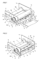
- the thermal transfer printer comprises a chassis 1 of metal, a print head 2 for printing, a platen roller 3 (see Fig. 12) opposed to the print head 2, a feed roller 4 (see Fig. 12) of metal, a feed roller gear 5, a press roller 6 (see Fig.
- the chassis 1 has a first side surface 1a, a second side surface 1b and a bottom surface 1c.
- the aforementioned bracket 13 is mounted on the first side surface 1a of the chassis 1.
- a sheet width recognition switch member 27 (see Fig. 5) having three switches is provided inside the first side surface 1a of the chassis 1.
- a receiving hole 1d for receiving the ink sheet cartridge 25 is provided on the second side surface 1b of the chassis 1.
- a sheet search sensor 28 (see Fig. 12) is provided on the bottom surface 1c of the chassis 1.
- the print head 2 includes a support shaft 2a, a head portion 2b and a head cover 2c (see Fig. 12) of resin mounted on the head portion 2b.
- a plurality of heating elements 2d generating heat upon application of a voltage pulse are aligned on the head portion 2b of the print head 2 at prescribed intervals along the width direction (direction X in Fig. 6) of the paper 14. 1280 heating elements 2d are so provided that each heating element 2d forms a dot in printing.
- a temperature sensor chip 29 for detecting the temperature around the heating elements 2d of the print head 2 is provided in the vicinity of the heating elements 2d on the bottom surface of the print head 2.
- Fig. 12 a temperature sensor chip 29 for detecting the temperature around the heating elements 2d of the print head 2 is provided in the vicinity of the heating elements 2d on the bottom surface of the print head 2.
- the print head 2 is mounted inside both side surfaces 1a and 1b of the chassis 1, to be rotatable about the support shaft 2a.
- the platen roller 3 (see Fig. 5) is rotatably supported by platen roller bearings (not shown) mounted on both side surfaces 1a and 1b of the chassis 1.
- the feed roller 4 has a feed roller gear insert portion 4a inserted into the feed roller gear 5.
- the feed roller 4 is rotatably supported by a feed roller bearing (not shown) mounted on the chassis 1.
- the press roller 6 is rotatably supported by a press roller bearing 6a mounted on a bearing support plate 6b.
- the bearing support plate 6b is arranged inside both side surfaces 1a and 1b of the chassis 1, for pressing the press roller 6 against the feed roller 4.
- a motor gear 15a is mounted on a shaft portion of the paper feed motor 15 mounted on the motor bracket 13.
- the paper feed motor 15 has a function serving as a drive source for driving a gear portion 12a of the take-up reel 12, the paper feed roller gear 9, the paper discharge roller gear 11 and the feed roller gear 5.
- the print head rotating motor 16 has a function of vertically rotating the print head 2 with a gear (not shown) for pressing and separating the print head 2 against and from the platen roller 3.
- the take-up reel 12 engages with a take-up bobbin 25c arranged in a take-up portion 25a of the ink sheet cartridge 25, thereby taking up an ink sheet 25e wound on the take-up bobbin 25c.
- the gear portion 12a of the take-up reel 12 meshes with the swing gear 17 upon swinging thereof.
- the lower paper guide 7a is set in the vicinity of the feed roller 4 (see Fig. 12) and the press roller 6.
- the lower paper guide 7a is provided with a paper width recognition switch member 30 having three switches, as shown in Figs. 1 and 2.
- the upper paper guide 7b is mounted on the upper portion of the lower paper guide 7a.
- the upper paper guide 7b has a function of guiding the paper 14 to a paper feed path toward a printing portion through the lower surface thereof in paper feeding while guiding the paper 14 to a paper discharge path through the upper surface thereof in paper discharge.
- the ink sheet cartridge 25 has the take-up portion 25a and a feed portion 25b.
- the take-up bobbin 25c is rotatably arranged in the take-up portion 25a of the ink sheet cartridge 25.
- a feed bobbin 25d is rotatably arranged in the feed portion 25b of the ink sheet cartridge 25.
- the ink sheet 25e for printing images on the paper 14 is wound on the take-up bobbin 25c and the feed bobbin 25d.
- This ink sheet 25e has three color printing sheets 25f, 25g and 25h of Y (yellow), M (magenta) and C (cyan) and transparent OP (overcoat) sheets 25i for protecting a print surface of the printed paper 14.
- Identification portions 25j recognized by the sheet search sensor 28 are provided between the color printing sheets 25f to 25h, while a further identification portion 25k recognized by the sheet search sensor 28 is provided between the printing sheet 25h of C (cyan) and the OP (overcoat) sheet 25i adjacent thereto.
- the ink sheet 25e is constituted of a base film layer 25m and a dye ink layer 25n.
- a contact portion 25p having three or less recess portions is provided on an end of the feed portion 25b of the ink sheet cartridge 25.
- Each recess portion of the contact portion 25p is provided in correspondence to any of the three switches of the sheet width recognition switch member 27.
- the switches of the sheet width recognition switch member 27 corresponding to the recess portions remain in non-input states when the ink sheet cartridge 25 is mounted on the thermal transfer printer, so that the ink sheet width is recognized through combination of an input switch and the non-input switches.
- another contact portion 26a having three or less recess portions is provided on an end surface of the paper feed cassette case 26.
- Each recess portion of the contact portion 26a is provided in correspondence to any of the three switches of the paper width recognition switch member 30.
- the switches of the paper width recognition switch member 30 corresponding to the recess portions remain in non-input states when the paper feed cassette case 26 is mounted on the thermal transfer printer, so that the width of the paper 14 can be recognized through combination of an input switch and the non-input switches.
- the paper 14 is constituted of a substrate 14c and a receptive layer 14d to which ink is transferred.
- the paper 14 has a print area 14a and a margin 14b around the print area 14a.
- the print area 14a has 1280 dots in the width direction (direction X1) of the paper 14 and 1800 lines in the longitudinal direction (direction Y1) of the paper 14.
- the "line” denotes the paper feed unit for the carried paper 14, and the thermal transfer printer performs printing while carrying the paper 14 line by line.
- the lines are examples of the "paper feed” in the present invention.
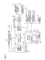
- the circuit portion 23 includes a control portion 23a controlling the printing operation of the thermal transfer printer, a head controller 23b controlling the temperatures of the heating elements 2d of the print head 2, a motor driver 23c, a motor controller 23d, an A-D conversion portion 23e, a ROM 23g having a color table 23f and a RAM 23h for developing the color table 23f.
- the motor driver 23d controls the print head rotating motor 16 and the paper feed motor 15 through the motor controller 23d.
- the head controller 23b controls the temperatures of the heating elements 2d of the print head 2 by applying a voltage pulse thereto.
- the A-D conversion portion 23e converts an analog voltage value detected by the temperature sensor chip 29 provided in the vicinity of the heating elements 2d of the print head 2 to a digital value.
- the color table 23f stores voltage pulse widths every gradation of the ink sheet 25e.
- the color table 23f stores temperatures corresponding to those detected by the temperature sensor chip 29 stored every degree centigrade in the temperature range of 0°C to 60°C and voltage pulse widths (relative values) corresponding to the respective gradations of the Y, M and C printing sheets 25f, 25g and 25h at the respective temperatures.
- the color table 23f stores gradations zero to 255, i.e., 256 gradations of the respective colors. Referring to Fig.
- the voltage pulse widths are examples of the "application time" in the present invention.
- the first and second values "30" and "50" in the parenthesis are the voltage pulse widths (relative values) of the gradations zero and 1 respectively.
- the voltage pulse width (relative value) of the gradation zero is about 2/3 of the voltage pulse width (relative value) of the gradation 1 at each temperature.
- the voltage pulse width (relative value) of the gradation zero is at such a value that no ink is printed on (transferred to) the paper 14 from the ink sheet 25e.
- the voltage pulse width (relative value) of the gradation zero is shorter than a pulse width for printing (transferring) the ink from the ink sheet 25e on (to) the paper 14.
- the levels of energy supplied to the heating elements 2d are reduced in order of the Y, C and M printing sheets 25f, 25h and 25g, and hence the color table 23f so stores the voltage pulse widths (relative values) to be reduced along the order of the Y, C and M printing sheets 25f, 25h and 25g.
- the thermal transfer printer employs the voltage pulse widths of the gradation zero of the color table 23f corresponding to each temperature for the voltage pulse applied to the heating elements 2d of the print head 2 before starting printing.
- control portion 23a has a function of issuing instructions to the motor controller 23d and the head controller 23b to apply a voltage pulse (see Fig. 9) to the heating elements 2d of the print head 2 by 10 lines with the voltage pulse widths of the gradation zero in the color table 23f (see Fig. 8) corresponding to each temperature while carrying the paper 14 after pressing the heating elements 2d of the print head 2 against the platen roller 3 through the paper 14 and the ink sheet 25e and before starting printing (point A in Fig. 9), as shown in Fig. 9.
- the control portion 23a is an example of the "print head control means" in the present invention.
- the control portion 23a is provided with a counter 23i (see Fig. 3) counting the number of lines in a paper discharge direction (direction Y1 in Fig. 11) for the paper 14 while also counting the number of dots (i) in the width direction (direction X1 in Fig. 11) of the paper 14.
- the control portion 23a determines whether or not the power supply portion 24 is in an ON-state. If the power supply portion 24 is in an OFF-state, the control portion 23a repeats this determination until the power supply portion 24 enters an ON-state. When the power supply portion 24 enters an ON-state, the control portion 23a determines whether or not a print button (not shown) has been pressed at a step S2. If the print button has not been pressed, the control portion 23a repeats this determination until the print button is pressed.
- the control portion 23a When determining that the print button has been pressed at the step S2, the control portion 23a reads the image data 22 for printing at a step S3. At a step S4, the control portion 23a develops the read image data 22 on the RAM 23h, and thereafter converts the image data 22 from RGB data to CMY data.
- the RGB data is constituted of the three primary colors (R (red), G (green) and B (blue)) of light
- the CMY data is constituted of the three primary colors (C (cyan), M (magenta) and Y (yellow)) of color materials.
- the control portion 23a initializes the counter 23i provided thereon and sets the values, which are variables, of the lines (line) and the dots (i) to zero.
- the control portion 23a feeds the paper 14 from the paper feed cassette case 26 (see Fig. 1) toward a printing start position and determines whether or not the paper 14 has reached the printing start position.
- the sheet search sensor 28 In the operation of feeding the paper 14 at the step S6, the sheet search sensor 28 first recognizes the identification portion 25j provided on the head of the Y (yellow) printing sheet 25f (see Fig. 7), as shown in Fig. 12. Thus, the sheet search sensor 28 searches for the Y (yellow) printing sheet 25f.
- the control portion 23a so drives the paper feed motor 15 that the motor gear 15a mounted thereon rotates along arrow C3 in Fig. 4, thereby rotating the feed roller gear 5 along arrow C1 in Fig. 4 through the intermediate gears 18 and 19.
- the paper feed roller gear 9 rotates along arrow C4 in Fig. 4 through the intermediate gears 20 and 21.
- the paper feed roller 8 rotates along arrow C4 in Fig. 12 following the rotation of the paper feed roller gear 9, thereby carrying the paper 14 in contact with the lower surface of the paper feed roller 8 in a paper feed direction (along arrow T1 in Fig. 12). Thereafter the lower paper guide 7a guides the paper 14 carried by the paper feed roller 8 to progress along the paper feed direction, so that the feed roller 4 and the press roller 6 carry the same to the printing start position.
- the swingable swing gear 17 swings to separate from the gear portion 12a of the take-up reel 12 (along arrow C2 in Fig. 4), not to mesh with the gear portion 12a of the take-up reel 12.
- the gear portion 12a of the take-up reel 12 remains unrotational in paper feeding, not to take up the ink sheet 25e wound on the take-up bobbin 25c and the feed bobbin 25d.
- the heating elements 2d of the print head 2 press the margin 14b of the paper 14 separated from the print area 14a by 10 lines on the printing start position.
- the control portion 23a drives the print head rotating motor 16 through the motor driver 23c and the motor controller 23d.
- the head portion 2b of the print head 2 rotates toward the platen roller 3.
- the heating elements 2d of the print head 2 press the platen roller 3 through the ink sheet 25e and the paper 14.
- the heating elements 2d of the print head 2 press the margin 14b of the paper 14 separated from the print area 14a by 10 lines.
- the temperature sensor chip 29 detects the temperature around the heating elements 2d as an analog voltage value.
- the A-D conversion portion 23e converts the detected analog voltage value to digital temperature data.
- the control portion 23a performs a line printing subroutine.
- the control portion 23a increases the temperatures of the heating elements 2d of the print head 2 to about 30°C, i.e., a level proper for starting printing beforehand, and thereafter performs normal printing. More specifically, the control portion 23a applies the voltage pulse to the heating elements 2d of the print head 2 while freely running (carrying) the paper 14 for 10 lines from a line A to a line B in Fig. 9 after the heating elements 2d of the print head 2 press the platen roller 3 on the line A in Fig. 9 and before starting the printing. Thereafter the control portion 23a performs normal printing from the print area 14a (line B in Fig. 9) of the paper 14.
- the motor gear 15a mounted on the paper feed motor 15 rotates along arrow D3 in Fig. 4 following driving of the paper feed motor 15, so that the feed roller gear 5 rotates along arrow D1 in Fig. 4 through the intermediate gears 18 and 19.
- the feed roller 4 rotates along arrow D1 in Fig. 13 following the rotation of the feed roller gear 5 along arrow D1 in Fig. 4, for carrying the paper 14 in the paper discharge direction (along arrow U1 in Fig. 13).
- the swingable swing gear 17 swings along arrow D2 in Fig. 4, to mesh with the gear 12a of the take-up reel 12.
- the gear portion 12a of the take-up reel 12 rotates along arrow D4 in Fig. 4, for taking up the ink sheet 25e wound on the take-up bobbin 25c and the feed bobbin 25d.
- the print head 2 rotates toward the platen roller 3 through the gears 16a and 16b (see Fig. 5) following driving of the print head rotating motor 16, so that the heating elements 2d press the platen roller 3 through the ink sheet 25e and the paper 14.
- the control potion 23a prints the ink from the Y (yellow) printing sheet 25f on the paper 14 with the heating elements 2d of the print head 2 while carrying the paper 14 in the paper discharge direction (along arrow U1 in Fig. 13) and taking up the ink sheet 25e.
- the upper paper guide 7b guides the paper 14 to a position carriable by the paper discharge roller 10, as shown in Fig. 14.
- the control portion 23a drives the print head rotating motor 16 to rotate the head portion 2b of the print head 2 in a direction for separating from the platen roller 3.
- the sheet search sensor 28 recognizes the identification portion 25j provided on the head of the M (magenta) printing sheet 25g, thereby searching for the M (magenta) printing sheet 25g.
- the motor gear 15a mounted thereon rotates along arrow C3 in Fig. 4 to rotate the feed roller gear 5 along arrow C1 in Fig. 4 through the intermediate gears 18 and 19.
- the feed roller 4 rotates along arrow C1 as shown in Fig. 13, so that the feed roller 4 and the press roller 6 carry the paper 14 to the printing start position.
- control portion 23a operates similarly to the above, for printing the ink from the M (magenta) printing sheet 25g on the paper 14. Thereafter the control portion 23a prints the ink from the C (cyan) printing sheet 25h and the transparent OP (overcoat) sheet 25i on the paper 14 similarly to the above, and completes the printing on the paper 14.
- the upper paper guide 7b guides the completely printed paper 14 so that the paper discharge roller 10 discharges the same, as shown in Fig. 14.
- the paper feed motor 15 and the respective gears operate similarly to the aforementioned case of carrying the paper 14 in the paper discharge direction (along arrow U1 in Fig. 13) in printing.
- the control portion 23a determines whether or not all lines (1810 lines) of the paper 14 have been completely printed at a step S10.
- the number of the lines is 1810 in total since the print area 14a of the paper 14 has the 1800 lines while the control portion 23a freely runs the paper 14 for 10 lines through the margin 14b, as shown in Fig. 11.
- the control portion 23a returns to the step S9 for the line printing subroutine.
- the control portion 23a determines whether or not the color printing sheets 25f to 25h have been completely printed.
- the control portion 23a determines that the color printing sheets 25f to 25h have not yet been completely printed, and repeats the printing operation at the steps S5 to S11 in order of the M (magenta) and C (cyan) printing sheets 25g and 25h.
- the control portion 23a determines whether or not the C (cyan) printing sheet 25h has been completely printed at a step S12.
- the control portion 23a repeats the printing operation at the steps S5 to S12 when determining that the C (cyan) printing sheet 25h has not yet been completely printed at the step S12, while advancing to a step S13 when determining that the C (cyan) printing sheet 25h has been completely printed at the step S12, for transferring the OP (overcoat) sheet 25i for protecting the ink transferred to the paper 14.
- the control portion 23a feeds the paper 14 and the ink sheet 25e in the paper discharge direction (along arrow U1 in Fig. 13) similarly to the aforementioned paper discharge operation, and turns off the power supply portion 24 at a step S14 for completing the printing operation on the paper 14.
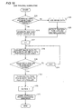
- the control portion 23a determines whether or not the number of lines (line) counted by the counter 23i is not more than 10 (whether or not in a free running period) at a step S15.
- the thermal transfer printer is in a state before starting printing, and the control portion 23a generates and uses dummy image data 22 as data converted to voltage pulse width data at a step S16.
- the color table 23f converts the dummy image data 22 of a gradation zero to voltage pulse width data of a gradation zero.
- control portion 23a sets the number of dots (i) to 1.
- control portion 23a converts dots of image data 22 having an i-th dot number to voltage pulse width data.
- control portion 23a develops the color table 23f (see Fig. 8) previously stored in the ROM 23g on the RAM 23h and converts the dots of the image data 22 having the i-th dot number to the voltage pulse width data through the data of the gradation zero of each of the printing sheets 25f to 25h at a temperature corresponding to the temperature around the heating elements 2d detected at the step S8 if the number of lines (line) counted by the counter 23i thereof is not more than 10.
- the control portion 23a determines whether or not image data 22 for one line (1280 dots) has been converted to voltage pulse width data. When determining that the image data 22 for one line (1280 dots) has not yet been converted to voltage pulse width data at the step S19, the control portion 23a sets the dots of the i-th dot number to a subsequent (i + 1)-th dot. At the step S18, the control portion 23a converts the dots of (i + 1)-th image data 22 to voltage pulse width data through the color table 23f. The control portion 23a repeats this operation until the number of dots (i) reaches 1280.
- the control portion 23a When determining that the image data 22 for one line (1280 dots) has been converted to voltage pulse width data at the step S19, on the other hand, the control portion 23a transfers the voltage pulse width data for one line (1280 dots) to the head controller 23b at a step S21. Then, the head controller 23b applies the voltage pulse of the gradation zero having the converted voltage pulse width to the heating elements 2d of the print head 2. At a step S22, the control portion 23a sets a next line number, and carries the paper 14 in the paper discharge direction (along arrow U1 in Fig. 13) by one line similarly to the aforementioned paper discharge operation at a step S23.
- the control portion 23a performing the line printing subroutine at the step S9 at a high speed, substantially simultaneously carries the paper 14 in the paper discharge direction and applies the voltage pulse to the heating elements 2d. Then, the control portion 23a completes the line printing subroutine at the step S9.
- the control portion 23a freely running the paper 14 for 10 lines before starting the printing as shown in Fig. 9, repeats the aforementioned steps S15 to S23 until the number of lines reaches 10.
- the control portion 23a increases the temperatures of the heating elements 2d to the level optimum for starting the printing by applying the voltage pulse data of the gradation zero to the heating elements 2d while carrying the paper 14.
- the control portion 23a When determining that the number of lines is at least 10 (not in free running) at the step S15, on the other hand, the control portion 23a performs the normal printing. More specifically, the control portion 23a uses image data 22 as the data converted to voltage pulse width data at a step S24. At the step S25, the temperature sensor chip 29 detects the temperature around the heating elements 2d as a voltage value, so that the A-D conversion portion 23e converts the detected voltage value from an analog value to a digital value utilized as temperature data.
- the control portion 23a sets the number of dots (i) to 1.
- the control portion 23a converts the dots of i-th image data 22 to voltage pulse width data through the color table 23f.
- the color table 23f stores the temperature corresponding to that around the heating elements 2d obtained at the step S25 and the voltage pulse width (relative value) corresponding to each gradation of each of the Y, M and C printing sheets 25f, 25g and 25h.
- the control portion 23a decides the voltage pulse width (relative value) as "50" and converts the image data 22 to voltage pulse width data of this value, as show in Fig. 8.
- the control portion 23a determines whether or not image data 22 for one line (1280 dots) has been converted to voltage pulse width data. When determining that the image data 22 for one line (1280 dots) has not yet been converted to voltage pulse width data at the step S19, the control portion 23a sets the dots of the i-th dot number to a subsequent (i + 1)-th dot at a step S20. At the step S18, the control portion 23a converts the dots of (i + 1)-th image data 22 to voltage pulse width data through the color table 23f. The control portion 23a repeats this operation until the number of dots (i) reaches 1280.
- the control portion 23a transfers the voltage pulse width data for one line (1280 dots) to the head controller 23b (see Fig. 3) at the step S21. Then, the head controller 23b applies the voltage pulse with the converted voltage pulse width to the heating elements 2d of the print head 2.
- the temperatures of the heating elements 2d of the print head 2 receiving the voltage pulse are increased due to resistance thereof, to melt the ink of the ink sheet 25e as shown in Fig. 9.
- the melted ink is transferred to the receptive layer 14d (see Fig. 10) of the paper 14, for forming an image based on the image data 22.
- the control portion 23a sets a next line number at the step S21, and carries the paper 14 in the paper discharge direction (along arrow U1 in Fig. 13) by one line similarly to the aforementioned paper discharge operation. Thus, the control portion 23a completes the line printing subroutine at the step S9.
- the control portion 23a repeats the aforementioned operation of printing the Y printing sheet 25f until completely printing the same on the 1800 lines.
- the control portion 23a feeds the paper 14 and the ink sheet 25e in the paper discharge direction (along arrow U1 in Fig. 13) while the print head 2 and the platen roller 3 are in contact with each other. Then, the control portion 23a repeats the aforementioned operation on the M and C printing sheets 25g and 25h and the OP sheet 25i.
- the thermal transfer printer comprising the control portion 23a applying the prescribed voltage pulse to the heating elements 2d of the print head 2 after pressing the print head 2 against the platen roller 3 and before starting printing as hereinabove described, can increase the temperatures of the heating elements 2d of the print head 2 to the proper level for starting printing beforehand, whereby reduction of print density can be suppressed in an initial stage of printing.
- the control portion 23a applies the prescribed voltage pulse to the heating elements 2d of the print head 2 while carrying the paper 14 for dispersing heat generated from the heating elements 2d to the paper 14 by carrying the paper 14, whereby the heat can be inhibited from locally remaining in the heating elements 2d dissimilarly to a case of applying the voltage pulse to the heating elements 2d of the print head 2 without carrying the paper 14. Therefore, the ink can be inhibited from adhering to the paper 14 also when the control portion 23a applies a voltage pulse higher than that locally leaving the heat in the heating elements 2d, whereby the time for increasing the temperatures of the heating elements 2d can be reduced by applying a high voltage pulse.
- the paper 14 is so arranged that the heating elements 2d of the print head 2 press the margin 14b of the paper 14 separated from the print area 14a of the paper 14 by the prescribed distance when the print head 2 presses the platen roller 3 before starting the printing and the control portion 23a applies the prescribed voltage pulse to the heating elements 2d of the print head 2 while carrying the paper 14 from the position where the heating elements 2d of the print head 2 press the margin 14b to the position where the heating elements 2d press the print area 14a so that the temperatures of the heating elements 2d of the print head 2 can be increased to the proper level for starting printing while the paper 14 is carried from the position where the heating elements 2d of the print head 2 press the margin 14b to the position where the heating elements 2d press the print area 14a, whereby the heating elements 2d of the print head 2 are at the proper temperature when reaching the print area 14a of the paper 14.
- the thermal transfer printer can simultaneously start the printing when the heating elements 2d of the print head 2 reach the print area 14a, not to delay the start of printing.
- control portion 23a applies the voltage pulse to the heating elements 2d of the print head 2 while carrying the paper 14 after pressing the print head 2 against the platen roller 3 and before starting printing every color of the ink sheet 25e, whereby the thermal transfer printer, capable of increasing the temperatures of the heating elements 2d to the level proper for starting the printing every color of the ink sheet 25e beforehand, can easily suppress reduction of print density in the initial stage of printing and improve printing quality.
- control portion 23a applies the voltage pulse to the heating elements 2d of the print head 2 with a voltage pulse width corresponding to a prescribed gradation of the color table 23f, whereby the thermal transfer printer, capable of applying the voltage pulse to the heating elements 2d with the optimum voltage pulse application width based on the temperature of the print head 2, can precisely increase the temperatures of the heating elements 2d to the level proper for starting the printing beforehand.
- the thermal transfer printer setting the voltage pulse width (relative value) of the gradation zero to the level shorter than the pulse width for printing (transferring) the ink from the ink sheet 25e on (to) the paper 14 can inhibit the ink from being printed on (transferred to) the paper 14 from the ink sheet 25e before starting the printing.
- the thermal transfer printer applying the voltage pulse on the basis of the dummy image data 22 while carrying the paper 14 before starting the printing, can apply the voltage pulse to the heating elements 2d of the print head 2 before starting printing in a method similar to that in the printing.
- the temperature sensor chip 29 detects the temperature around the heating elements 2d of the print head 2 every line while the control portion 23a applies the voltage pulse to the heating elements 2d of the print head 2 for the time corresponding to the temperature detected by the temperature sensor chip 29 every line when the heating elements 2d of the print head 2 pass through the margin 14b and reach the print area 14a of the paper 14, whereby the thermal transfer printer, capable of controlling the temperatures of the heating elements 2d of the print head 2 every line in normal printing after the heating elements 2d pass through the margin 14b, can further improve the printing quality.
- the present invention is not restricted to this but the paper may alternatively be so arranged that the heating elements of the print head press the print area of the paper when the print head presses the platen roller.
- the thermal transfer printer applies the voltage pulse to the heating elements of the print head with the prescribed voltage pulse width while carrying the paper before starting the printing in each color of the Y, M and C color printing sheets of the ink sheet in the aforementioned embodiment
- the thermal transfer printer may alternatively apply the voltage pulse to the heating elements of the print head with the prescribed voltage pulse width while carrying the paper only before starting printing in a prescribed one of the colors (Y, M and C) of the ink sheet.
- the thermal transfer printer may apply the voltage pulse to the heating elements of the print head with the prescribed voltage pulse width while carrying the paper before starting transferring the OP (overcoat) sheet, similarly to the aforementioned case of each of the colors (Y, M and C).
- the thermal transfer printer applies the voltage pulse to the heating elements of the print head while carrying the paper by 10 lines before starting the printing in the aforementioned embodiment
- the present invention is not restricted to this but the thermal transfer printer may alternatively carry the paper by a number of lines other than 10.
- the thermal transfer printer employs the voltage pulse width data of the gradation zero in the color table stored every temperature for applying the voltage pulse to the heating elements of the print head while carrying the paper in the aforementioned embodiment
- the present invention is not restricted to this but a color table recording only the voltage pulse width data for applying the voltage pulse to the heating elements of the print head while carrying the paper after pressing the print head against the platen roller and before starting printing may alternatively be created for deciding the voltage pulse width through the created color table.
- the thermal transfer printer controls the energy supplied to the heating elements of the print head by controlling the width of the voltage pulse in the aforementioned embodiment
- the present invention is not restricted to this but the thermal transfer printer may alternatively control the energy supplied to the heating elements by controlling a parameter (voltage value, for example) other than the width of the voltage pulse.
Landscapes
- Electronic Switches (AREA)
Abstract
Description
- The present invention relates to a printer, and more particularly, it relates to a printer comprising a print head.
- In relation to a printer such as a thermal transfer printer, various structures are generally proposed in order to suppress reduction of print density by applying a voltage pulse (dummy pulse) to a heating element of a thermal head (print head) while performing printing on a print area. For example,
Japanese Patent Laying-Open Nos. 56-161182 (1981 9-216398 (1997 - The aforementioned
Japanese Patent Laying-Open No. 56-161182 - The aforementioned
Japanese Patent Laying-Open No. 9-216398 - However, while the printers described in the aforementioned
Japanese Patent Laying-Open Nos. 56-161182 9-216398 - In this regard, a printer capable of increasing the temperature of a heating element of a thermal head (print head) to a proper level by applying a voltage pulse before starting printing (transfer) is proposed in general, as described in
Japanese Patent No. 3109386 - The aforementioned
Japanese Patent No. 3109386 Japanese Patent No. 3109386 - Also when the technique disclosed in the aforementioned
Japanese Patent No. 3109386 - The present invention has been proposed in order to solve the aforementioned problems, and an object of the present invention is to provide a printer capable of reducing a time for increasing the temperature of a heating element to a proper level for starting printing beforehand and suppressing density reduction in an initial stage of printing.
- A printer according to a first aspect of the present invention comprises a print head having a heating element for printing an image on a paper by transferring ink from an ink sheet to the paper, a platen roller against which the print head is pressed through the ink sheet and the paper and print head control means applying a prescribed voltage to the heating element of the print head while carrying the paper after pressing the print head against the platen roller and before starting printing.
- The printer according to the first aspect, comprising the print head control means applying the prescribed voltage to the heating element of the print head after pressing the print head against the platen roller and before starting printing as hereinabove described, can increase the temperature of the heating element of the print head to the proper level for starting printing beforehand, whereby reduction of print density can be suppressed in an initial stage of printing. Further, the print head control means applies the prescribed voltage to the heating element of the print head while carrying the paper for dispersing heat generated from the heating element by carrying the paper, whereby the heat can be inhibited from locally remaining in the heating element dissimilarly to a case of applying the voltage to the heating element of the print head without carrying the paper. Therefore, the ink can be inhibited from adhering to the paper also when the print head control means applies a voltage higher than that locally leaving the heat in the heating element, whereby the time for increasing the temperature of the heating element can be reduced by applying a high voltage. According to the present invention, not only characters but also images can be printed with the print head.
- In the aforementioned printer according to the first aspect, the paper is preferably so arranged that the heating element of the print head presses a margin of the paper separated from a print area of the paper by a prescribed distance when the print head presses the platen roller before starting the printing, and the print head control means preferably applies the prescribed voltage to the heating element of the print head while carrying the paper from a position where the heating element of the print head presses the margin to a position where the heating element presses the print area. According to this structure, the temperature of the heating element of the print head can be increased to the proper level for starting printing while the paper is carried from the position where the heating element of the print head presses the margin to the position where the heating element presses the print area, whereby the heating element of the print head is at the proper temperature when reaching the print area of the paper. Thus, the printer can simultaneously start the printing when the heating element of the print head reaches the print area, not to delay the start of printing.
- In this case, the printer preferably starts the printing by applying the prescribed voltage to the heating element of the print head on the basis of image data for the printing when the heating element of the print head passes through the margin and reaches the print area of the paper. According to this structure, the printer can easily simultaneously start the printing when the heating element of the print head reaches the print area of the paper.
- In the aforementioned printer according to the first aspect, the ink sheet preferably has a sheet of a plurality of colors, and the print head control means preferably applies the voltage to the heating element of the print head while carrying the paper after pressing the print head against the platen roller and before starting printing every color of the ink sheet. According to this structure, the printer, capable of increasing the temperature of the heating element to the level proper for starting the printing every color of the ink sheet beforehand, can easily suppress reduction of print density in the initial stage of printing and improve printing quality.
- In the aforementioned printer according to the first aspect, the voltage is preferably a voltage pulse, and the print head control means preferably applies the voltage pulse to the heating element of the print head by a prescribed paper feed while carrying the paper before starting the printing. According to this structure, the printer can easily control the temperature of the heating element by changing the width of the voltage pulse. Further, the printer, capable of increasing the temperature of the heating element by applying the voltage pulse to the heating element by the prescribed feed, can control the temperature of the heating element also according to this structure.
- The aforementioned printer applying the voltage pulse preferably further comprises a color table provided in correspondence to every prescribed temperature of the print head for deciding an application time of the voltage pulse applied to the heating element of the print head, and the print head control means preferably applies the voltage pulse to the heating element of the print head for an application time corresponding to a prescribed gradation of the color table. According to this structure, the printer, capable of applying the voltage pulse to the heating element for the optimum voltage pulse application time based on the temperature of the print head, can precisely increase the temperature of the heating element to the level proper for starting the printing beforehand.
- In the aforementioned printer comprising the color table, the color table preferably includes a plurality of voltage pulse width data corresponding to a plurality of colors respectively, and the print head control means preferably applies the voltage pulse to the heating element of the print head for a time corresponding to the voltage pulse width data of a gradation zero of each of the plurality of colors before starting the printing. According to this structure, the printer can easily inhibit the temperature of the heating element of the print head from excessive increase before starting printing every sheet in the plurality of colors corresponding to the plurality of voltage pulse width data respectively.
- In this case, the application time corresponding to the voltage pulse width data of the gradation zero is preferably shorter than an application time for transferring the ink from the ink sheet to the paper. According to this structure, the printer can inhibit the ink from transfer from the ink sheet to the paper before starting the printing.
- In the aforementioned printer applying the voltage pulse, the print head control means preferably applies the voltage pulse on the basis of dummy image data while carrying the paper before starting the printing. According to this structure, the printer can apply the voltage pulse to the heating element of the print head before starting the printing in a method similar to that in the printing.
- The aforementioned printer applying the voltage pulse preferably further comprises a temperature sensor chip for detecting the temperature around the heating element of the print head, and the print head control means preferably applies the voltage pulse to the heating element of the print head by a plurality of lines for a time corresponding to the temperature detected by the temperature sensor chip while the heating element of the print head passes through a margin of the paper separated from a print area of the paper by a prescribed distance. According to this structure, the printer, capable of applying the voltage pulse to the heating element for the optimum voltage pulse application time based on the temperature of the print head, can precisely increase the temperature of the heating element to the level proper for starting the printing beforehand.
- In this case, the temperature sensor chip preferably detects the temperature around the heating element of the print head every line while the print head control means applies the voltage pulse to the heating element of the print head for a time corresponding to the temperature detected by the temperature sensor chip every line when the heating element of the print head passes through the margin and reaches the print area of the paper. According to this structure, the printer, capable of controlling the temperature of the heating element of the print head every line in normal printing after the heating element passes through the margin, can improve printing quality.
- A printer according to a second aspect of the present invention comprises a print head having a heating element for printing an image on a paper by transferring ink of an ink sheet having a sheet of a plurality of colors to the paper, a platen roller against which the print head is pressed through the ink sheet and the paper, print head control means applying a prescribed voltage pulse to the heating element of the print head and a color table provided in correspondence to every prescribed temperature of the print head for deciding an application time of the voltage pulse applied to the heating element of the print head, the paper is so arranged that the heating element of the print head presses a margin of the paper separated from a print area of the paper by a prescribed distance when the print head presses the platen roller before starting the printing, and the print head control means applies the prescribed voltage pulse to the heating element of the print head for an application time corresponding to a prescribed gradation of the color table by a prescribed paper feed while carrying the paper from a position where the heating element of the print head presses the margin to a position where the heating element presses the print area after pressing the print head against the platen roller and before starting printing every color of the ink sheet.
- As hereinabove described, the printer according to the second aspect, comprising the print head control means applying the prescribed voltage pulse to the heating element of the print head after pressing the print head against the platen roller and before starting printing as hereinabove described, can increase the temperature of the heating element of the print head to a proper level for starting printing beforehand, whereby reduction of print density can be suppressed in an initial stage of printing. Further, the print head control means applies the prescribed voltage pulse to the heating element of the print head while carrying the paper for dispersing heat generated from the heating element by carrying the paper, whereby the heat can be inhibited from locally remaining in the heating element dissimilarly to a case of applying the voltage pulse to the heating element of the print head without carrying the paper. Therefore, the ink can be inhibited from adhering to the paper also when the print head control means applies a voltage pulse higher than that locally leaving the heat in the heating element, whereby the time for increasing the temperature of the heating element can be reduced by applying a high voltage pulse. According to the present invention, not only characters but also images can be printed with the print head. Further, the paper is so arranged that the heating element of the print head presses the margin of the paper separated from the print area of the paper by the prescribed distance when the print head presses the platen roller before starting the printing, and the print head control means applies the prescribed voltage pulse to the heating element of the print head while carrying the paper from the position where the heating element of the print head presses the margin to the position where the heating element presses the print area so that the temperature of the heating element of the print head can be increased to the proper level for starting printing while the paper is carried from the position where the heating element of the print head presses the margin to the position where the heating element presses the print area, whereby the heating element of the print head is at the proper temperature when reaching the print area of the paper. Thus, the printer can simultaneously start the printing when the heating element of the print head reaches the print area, not to delay the start of printing. In addition, the print head control means applies the voltage pulse to the heating element of the print head while carrying the paper after pressing the print head against the platen roller and before starting printing every color of the ink sheet, whereby the printer, capable of increasing the temperature of the heating element to the level proper for starting the printing every color of the ink sheet beforehand, can easily suppress reduction of print density in the initial stage of printing and improve printing quality. Further, the print head control means applies the voltage pulse to the heating element of the print head for an application time corresponding to a prescribed gradation of the color table, whereby the printer, capable of applying the voltage pulse to the heating element for the optimum voltage pulse application time based on the temperature of the print head regardless of the temperature of the print head, can precisely increase the temperature of the heating element to the level proper for starting the printing beforehand.
- The aforementioned printer according to the second aspect preferably starts the printing by applying the prescribed voltage pulse to the heating element of the print head on the basis of image data for the printing when the heating element of the print head passes through the margin and reaches the print area of the paper. According to this structure, the printer can easily simultaneously start the printing when the heating element of the print head reaches the print area of the paper.
- In the aforementioned printer according to the second aspect, the color table preferably includes a plurality of voltage pulse width data corresponding to the plurality of colors respectively, and the print head control means preferably applies the voltage pulse to the heating element of the print head for a time corresponding to the voltage pulse width data of a gradation zero of each of the plurality of colors before starting the printing. According to this structure, the printer can easily inhibit the temperature of the heating element of the print head from excessive increase before starting printing every sheet in the plurality of colors corresponding to the plurality of voltage pulse width data respectively.
- In this case, the application time corresponding to the voltage pulse width data of the gradation zero is preferably shorter than an application time for transferring the ink from the ink sheet to the paper. According to this structure, the printer can inhibit the ink from transfer from the ink sheet to the paper before starting the printing.
- In the aforementioned printer according to the second aspect, the print head control means preferably applies the voltage pulse on the basis of dummy image data while carrying the paper before starting the printing. According to this structure, the printer can apply the voltage pulse to the heating element of the print head before starting the printing in a method similar to that in the printing.
- The aforementioned printer according to the second aspect preferably further comprises a temperature sensor chip for detecting the temperature around the heating element of the print head, and the print head control means preferably applies the voltage pulse to the heating element of the print head by a plurality of lines for a time corresponding to the temperature detected by the temperature sensor chip while the heating element of the print head passes through the margin. According to this structure, the printer, capable of applying the voltage pulse to the heating element for the optimum voltage pulse application time based on the temperature of the print head, can precisely increase the temperature of the heating element to the level proper for starting the printing beforehand.
- In this case, the temperature sensor chip preferably detects the temperature around the heating element of the print head every line while the print head control means applies the voltage pulse to the heating element of the print head for a time corresponding to the temperature detected by the temperature sensor chip every line when the heating element of the print head passes through the margin and reaches the print area of the paper. According to this structure, the printer, capable of controlling the temperature of the heating element of the print head every line in normal printing after the heating element passes through the margin, can improve printing quality.
- The foregoing and other objects, features, aspects and advantages of the present invention will become more apparent from the following detailed description of the present invention when taken in conjunction with the accompanying drawings.
- IN THE DRAWINGS:
- Fig. 1 is a perspective view showing the overall structure of a thermal transfer printer according to an embodiment of the present invention;
- Fig. 2 is a perspective view of the thermal transfer printer according to the embodiment of the present invention shown in Fig. 1, from which an ink sheet cartridge is removed;
- Fig. 3 is a block diagram showing the circuit structure of the thermal transfer printer according to the embodiment of the present invention shown in Fig. 1;
- Fig. 4 is a front elevational view showing a stepping motor and respective gears of the thermal transfer printer according to the embodiment of the present invention shown in Fig. 1;
- Fig. 5 is a plan view of the thermal transfer printer according to the embodiment of the present invention shown in Fig. 1;
- Fig. 6 is a detailed diagram of a print head of the thermal transfer printer according to the embodiment of the present invention shown in Fig. 1;
- Fig. 7 illustrates an exemplary color table in the thermal transfer printer according to the embodiment of the present invention shown in Fig. 1;
- Fig. 8 is a diagram for illustrating an ink sheet of the thermal transfer printer according to the embodiment of the present invention shown in Fig. 1;
- Fig. 9 illustrates a temperature buildup curve of a heating element of the thermal transfer printer according to the embodiment of the present invention shown in Fig. 1;
- Fig. 10 is a sectional view for illustrating ink transfer in the thermal transfer printer according to the embodiment of the present invention shown in Fig. 1;
- Fig. 11 is a plan view of a paper employed in the thermal transfer printer according to the embodiment of the present invention shown in Fig. 1;
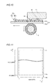
- Figs. 12 to 14 are sectional view of the thermal transfer printer according to the embodiment of the present invention shown in Fig. 1;
- Fig. 15 is a flow chart for illustrating a printing operation of the thermal transfer printer according to the embodiment of the present invention shown in Fig. 1; and
- Fig. 16 is a flow chart for illustrating operations in a line printing subroutine at a step S9 shown in Fig. 15.
- An embodiment of the present invention is now described with reference to the drawings.
- First, the structure of a thermal transfer printer according to the embodiment of the present invention is described with reference to Figs. 1 to 13. According to this embodiment, the present invention is applied to the thermal transfer printer, which is an exemplary printer.
- As shown in Figs. 1 and 2, the thermal transfer printer according to this embodiment of the present invention comprises a
chassis 1 of metal, aprint head 2 for printing, a platen roller 3 (see Fig. 12) opposed to theprint head 2, a feed roller 4 (see Fig. 12) of metal, afeed roller gear 5, a press roller 6 (see Fig. 12) of metal pressing thefeed roller 4 with prescribed pressing force, alower paper guide 7a of resin, anupper paper guide 7b of resin, apaper feed roller 8 of rubber, a paperfeed roller gear 9, apaper discharge roller 10 of rubber, a paperdischarge roller gear 11, a take-up reel 12, amotor bracket 13, apaper feed motor 15 for carrying apaper 14, a printhead rotating motor 16 rotating theprint head 2, aswingable swing gear 17, a plurality ofintermediate gears 18 to 21 (see Fig. 4), a circuit portion 23 (see Fig. 3) controlling the thermal transfer printer on the basis of image data 22 (see Fig. 3) for printing and a power supply portion 24 (see Fig. 3) for supplying power to the thermal transfer printer. Anink sheet cartridge 25 and a paperfeed cassette case 26 for storing thepaper 14 fed to the thermal transfer printer are mounted on the thermal transfer printer according to this embodiment, as shown in Fig. 1. - As shown in Figs. 1 and 2, the
chassis 1 has afirst side surface 1a, asecond side surface 1b and abottom surface 1c. Theaforementioned bracket 13 is mounted on thefirst side surface 1a of thechassis 1. A sheet width recognition switch member 27 (see Fig. 5) having three switches is provided inside thefirst side surface 1a of thechassis 1. A receivinghole 1d for receiving theink sheet cartridge 25 is provided on thesecond side surface 1b of thechassis 1. Further, a sheet search sensor 28 (see Fig. 12) is provided on thebottom surface 1c of thechassis 1. - The
print head 2 includes asupport shaft 2a, ahead portion 2b and ahead cover 2c (see Fig. 12) of resin mounted on thehead portion 2b. As shown in Fig. 6, a plurality ofheating elements 2d generating heat upon application of a voltage pulse are aligned on thehead portion 2b of theprint head 2 at prescribed intervals along the width direction (direction X in Fig. 6) of thepaper 14. 1280heating elements 2d are so provided that eachheating element 2d forms a dot in printing. As shown in Fig. 12, atemperature sensor chip 29 for detecting the temperature around theheating elements 2d of theprint head 2 is provided in the vicinity of theheating elements 2d on the bottom surface of theprint head 2. As shown in Fig. 2, theprint head 2 is mounted inside bothside surfaces chassis 1, to be rotatable about thesupport shaft 2a. The platen roller 3 (see Fig. 5) is rotatably supported by platen roller bearings (not shown) mounted on bothside surfaces chassis 1. - As shown in Fig. 4, the
feed roller 4 has a feed rollergear insert portion 4a inserted into thefeed roller gear 5. Thefeed roller 4 is rotatably supported by a feed roller bearing (not shown) mounted on thechassis 1. As shown in Figs. 2 and 5, thepress roller 6 is rotatably supported by apress roller bearing 6a mounted on a bearingsupport plate 6b. The bearingsupport plate 6b is arranged inside bothside surfaces chassis 1, for pressing thepress roller 6 against thefeed roller 4. - As shown in Fig. 4, a
motor gear 15a is mounted on a shaft portion of thepaper feed motor 15 mounted on themotor bracket 13. Thepaper feed motor 15 has a function serving as a drive source for driving agear portion 12a of the take-up reel 12, the paperfeed roller gear 9, the paperdischarge roller gear 11 and thefeed roller gear 5. The printhead rotating motor 16 has a function of vertically rotating theprint head 2 with a gear (not shown) for pressing and separating theprint head 2 against and from theplaten roller 3. - The take-
up reel 12 engages with a take-upbobbin 25c arranged in a take-upportion 25a of theink sheet cartridge 25, thereby taking up anink sheet 25e wound on the take-upbobbin 25c. As shown in Fig. 5, thegear portion 12a of the take-up reel 12 meshes with theswing gear 17 upon swinging thereof. - As shown in Figs. 1, 2 and 12, the
lower paper guide 7a is set in the vicinity of the feed roller 4 (see Fig. 12) and thepress roller 6. Thelower paper guide 7a is provided with a paper widthrecognition switch member 30 having three switches, as shown in Figs. 1 and 2. Theupper paper guide 7b is mounted on the upper portion of thelower paper guide 7a. Theupper paper guide 7b has a function of guiding thepaper 14 to a paper feed path toward a printing portion through the lower surface thereof in paper feeding while guiding thepaper 14 to a paper discharge path through the upper surface thereof in paper discharge. - As shown in Figs. 1 and 2, the
ink sheet cartridge 25 has the take-upportion 25a and afeed portion 25b. As shown in Fig. 12, the take-upbobbin 25c is rotatably arranged in the take-upportion 25a of theink sheet cartridge 25. Further, afeed bobbin 25d is rotatably arranged in thefeed portion 25b of theink sheet cartridge 25. Theink sheet 25e for printing images on thepaper 14 is wound on the take-upbobbin 25c and thefeed bobbin 25d. Thisink sheet 25e has threecolor printing sheets sheets 25i for protecting a print surface of the printedpaper 14.Identification portions 25j recognized by thesheet search sensor 28 are provided between thecolor printing sheets 25f to 25h, while afurther identification portion 25k recognized by thesheet search sensor 28 is provided between theprinting sheet 25h of C (cyan) and the OP (overcoat)sheet 25i adjacent thereto. As shown in Fig. 10, theink sheet 25e is constituted of abase film layer 25m and adye ink layer 25n. - As shown in Fig. 5, a
contact portion 25p having three or less recess portions is provided on an end of thefeed portion 25b of theink sheet cartridge 25. Each recess portion of thecontact portion 25p is provided in correspondence to any of the three switches of the sheet widthrecognition switch member 27. Thus, the switches of the sheet widthrecognition switch member 27 corresponding to the recess portions remain in non-input states when theink sheet cartridge 25 is mounted on the thermal transfer printer, so that the ink sheet width is recognized through combination of an input switch and the non-input switches. - As shown in Fig. 1, another
contact portion 26a having three or less recess portions is provided on an end surface of the paperfeed cassette case 26. Each recess portion of thecontact portion 26a is provided in correspondence to any of the three switches of the paper widthrecognition switch member 30. Thus, the switches of the paper widthrecognition switch member 30 corresponding to the recess portions remain in non-input states when the paperfeed cassette case 26 is mounted on the thermal transfer printer, so that the width of thepaper 14 can be recognized through combination of an input switch and the non-input switches. - As shown in Fig. 10, the
paper 14 is constituted of a substrate 14c and areceptive layer 14d to which ink is transferred. As shown in Fig. 11, thepaper 14 has aprint area 14a and amargin 14b around theprint area 14a. Theprint area 14a has 1280 dots in the width direction (direction X1) of thepaper paper 14. The "line" denotes the paper feed unit for the carriedpaper 14, and the thermal transfer printer performs printing while carrying thepaper 14 line by line. The lines are examples of the "paper feed" in the present invention. - As shown in Fig. 3, the
circuit portion 23 includes acontrol portion 23a controlling the printing operation of the thermal transfer printer, ahead controller 23b controlling the temperatures of theheating elements 2d of theprint head 2, amotor driver 23c, amotor controller 23d, anA-D conversion portion 23e, aROM 23g having a color table 23f and aRAM 23h for developing the color table 23f. Themotor driver 23d controls the printhead rotating motor 16 and thepaper feed motor 15 through themotor controller 23d. Thehead controller 23b controls the temperatures of theheating elements 2d of theprint head 2 by applying a voltage pulse thereto. TheA-D conversion portion 23e converts an analog voltage value detected by thetemperature sensor chip 29 provided in the vicinity of theheating elements 2d of theprint head 2 to a digital value. - As shown in Fig. 8, the color table 23f stores voltage pulse widths every gradation of the
ink sheet 25e. For example, the color table 23f stores temperatures corresponding to those detected by thetemperature sensor chip 29 stored every degree centigrade in the temperature range of 0°C to 60°C and voltage pulse widths (relative values) corresponding to the respective gradations of the Y, M andC printing sheets - With reference to the
Y printing sheet 25f at the temperature of 60°C, the first and second values "30" and "50" in the parenthesis (30, 50, 51, ..., 198, 200) are the voltage pulse widths (relative values) of the gradations zero and 1 respectively. In each of the Y, M andC printing sheets gradation 1 at each temperature. Further, the voltage pulse width (relative value) of the gradation zero is at such a value that no ink is printed on (transferred to) thepaper 14 from theink sheet 25e. In other words, the voltage pulse width (relative value) of the gradation zero is shorter than a pulse width for printing (transferring) the ink from theink sheet 25e on (to) thepaper 14. In addition, the levels of energy supplied to theheating elements 2d are reduced in order of the Y, C andM printing sheets M printing sheets - According to this embodiment, the thermal transfer printer employs the voltage pulse widths of the gradation zero of the color table 23f corresponding to each temperature for the voltage pulse applied to the
heating elements 2d of theprint head 2 before starting printing. - According to this embodiment, the
control portion 23a has a function of issuing instructions to themotor controller 23d and thehead controller 23b to apply a voltage pulse (see Fig. 9) to theheating elements 2d of theprint head 2 by 10 lines with the voltage pulse widths of the gradation zero in the color table 23f (see Fig. 8) corresponding to each temperature while carrying thepaper 14 after pressing theheating elements 2d of theprint head 2 against theplaten roller 3 through thepaper 14 and theink sheet 25e and before starting printing (point A in Fig. 9), as shown in Fig. 9. Thecontrol portion 23a is an example of the "print head control means" in the present invention. - The
control portion 23a is provided with acounter 23i (see Fig. 3) counting the number of lines in a paper discharge direction (direction Y1 in Fig. 11) for thepaper 14 while also counting the number of dots (i) in the width direction (direction X1 in Fig. 11) of thepaper 14. - The printing operation of the thermal printer according to the embodiment of the present invention for each color of the
ink sheet 25e is described with reference to Figs. 1, 4, 5, 7, 9 and 11 to 15. At a step S1, thecontrol portion 23a determines whether or not thepower supply portion 24 is in an ON-state. If thepower supply portion 24 is in an OFF-state, thecontrol portion 23a repeats this determination until thepower supply portion 24 enters an ON-state. When thepower supply portion 24 enters an ON-state, thecontrol portion 23a determines whether or not a print button (not shown) has been pressed at a step S2. If the print button has not been pressed, thecontrol portion 23a repeats this determination until the print button is pressed. When determining that the print button has been pressed at the step S2, thecontrol portion 23a reads theimage data 22 for printing at a step S3. At a step S4, thecontrol portion 23a develops the readimage data 22 on theRAM 23h, and thereafter converts theimage data 22 from RGB data to CMY data. The RGB data is constituted of the three primary colors (R (red), G (green) and B (blue)) of light, while the CMY data is constituted of the three primary colors (C (cyan), M (magenta) and Y (yellow)) of color materials. At a step S5, thecontrol portion 23a initializes thecounter 23i provided thereon and sets the values, which are variables, of the lines (line) and the dots (i) to zero. At a step S6, thecontrol portion 23a feeds thepaper 14 from the paper feed cassette case 26 (see Fig. 1) toward a printing start position and determines whether or not thepaper 14 has reached the printing start position. - In the operation of feeding the
paper 14 at the step S6, thesheet search sensor 28 first recognizes theidentification portion 25j provided on the head of the Y (yellow)printing sheet 25f (see Fig. 7), as shown in Fig. 12. Thus, thesheet search sensor 28 searches for the Y (yellow)printing sheet 25f. In this paper feed operation, thecontrol portion 23a so drives thepaper feed motor 15 that themotor gear 15a mounted thereon rotates along arrow C3 in Fig. 4, thereby rotating thefeed roller gear 5 along arrow C1 in Fig. 4 through theintermediate gears feed roller gear 5 along arrow C1 in Fig. 4, the paperfeed roller gear 9 rotates along arrow C4 in Fig. 4 through theintermediate gears paper feed roller 8 rotates along arrow C4 in Fig. 12 following the rotation of the paperfeed roller gear 9, thereby carrying thepaper 14 in contact with the lower surface of thepaper feed roller 8 in a paper feed direction (along arrow T1 in Fig. 12). Thereafter thelower paper guide 7a guides thepaper 14 carried by thepaper feed roller 8 to progress along the paper feed direction, so that thefeed roller 4 and thepress roller 6 carry the same to the printing start position. - As shown in Fig. 4, the
swingable swing gear 17 swings to separate from thegear portion 12a of the take-up reel 12 (along arrow C2 in Fig. 4), not to mesh with thegear portion 12a of the take-up reel 12. Thus, thegear portion 12a of the take-up reel 12 remains unrotational in paper feeding, not to take up theink sheet 25e wound on the take-upbobbin 25c and thefeed bobbin 25d. - According to this embodiment, the
heating elements 2d of theprint head 2 press themargin 14b of thepaper 14 separated from theprint area 14a by 10 lines on the printing start position. - At a step S7, the
control portion 23a drives the printhead rotating motor 16 through themotor driver 23c and themotor controller 23d. Following this driving of the printhead rotating motor 16, thehead portion 2b of theprint head 2 rotates toward theplaten roller 3. Thus, theheating elements 2d of theprint head 2 press theplaten roller 3 through theink sheet 25e and thepaper 14. At this time, theheating elements 2d of theprint head 2 press themargin 14b of thepaper 14 separated from theprint area 14a by 10 lines. At a step S8, thetemperature sensor chip 29 detects the temperature around theheating elements 2d as an analog voltage value. TheA-D conversion portion 23e converts the detected analog voltage value to digital temperature data. - At a step S9, the
control portion 23a performs a line printing subroutine. In this line printing subroutine at the step S9, thecontrol portion 23a increases the temperatures of theheating elements 2d of theprint head 2 to about 30°C, i.e., a level proper for starting printing beforehand, and thereafter performs normal printing. More specifically, thecontrol portion 23a applies the voltage pulse to theheating elements 2d of theprint head 2 while freely running (carrying) thepaper 14 for 10 lines from a line A to a line B in Fig. 9 after theheating elements 2d of theprint head 2 press theplaten roller 3 on the line A in Fig. 9 and before starting the printing. Thereafter thecontrol portion 23a performs normal printing from theprint area 14a (line B in Fig. 9) of thepaper 14. - In the normal printing, the
motor gear 15a mounted on thepaper feed motor 15 rotates along arrow D3 in Fig. 4 following driving of thepaper feed motor 15, so that thefeed roller gear 5 rotates along arrow D1 in Fig. 4 through theintermediate gears feed roller 4 rotates along arrow D1 in Fig. 13 following the rotation of thefeed roller gear 5 along arrow D1 in Fig. 4, for carrying thepaper 14 in the paper discharge direction (along arrow U1 in Fig. 13). Theswingable swing gear 17 swings along arrow D2 in Fig. 4, to mesh with thegear 12a of the take-up reel 12. Thus, thegear portion 12a of the take-up reel 12 rotates along arrow D4 in Fig. 4, for taking up theink sheet 25e wound on the take-upbobbin 25c and thefeed bobbin 25d. - At this time, the
print head 2 rotates toward theplaten roller 3 through thegears head rotating motor 16, so that theheating elements 2d press theplaten roller 3 through theink sheet 25e and thepaper 14. Thecontrol potion 23a prints the ink from the Y (yellow)printing sheet 25f on thepaper 14 with theheating elements 2d of theprint head 2 while carrying thepaper 14 in the paper discharge direction (along arrow U1 in Fig. 13) and taking up theink sheet 25e. When thecontrol portion 23a completely prints the ink from the Y (yellow)printing sheet 25f, theupper paper guide 7b guides thepaper 14 to a position carriable by thepaper discharge roller 10, as shown in Fig. 14. - Then, the
control portion 23a drives the printhead rotating motor 16 to rotate thehead portion 2b of theprint head 2 in a direction for separating from theplaten roller 3. Further, thesheet search sensor 28 recognizes theidentification portion 25j provided on the head of the M (magenta)printing sheet 25g, thereby searching for the M (magenta)printing sheet 25g. Following driving of thepaper feed motor 15, themotor gear 15a mounted thereon rotates along arrow C3 in Fig. 4 to rotate thefeed roller gear 5 along arrow C1 in Fig. 4 through theintermediate gears feed roller 4 rotates along arrow C1 as shown in Fig. 13, so that thefeed roller 4 and thepress roller 6 carry thepaper 14 to the printing start position. Then, thecontrol portion 23a operates similarly to the above, for printing the ink from the M (magenta)printing sheet 25g on thepaper 14. Thereafter thecontrol portion 23a prints the ink from the C (cyan)printing sheet 25h and the transparent OP (overcoat)sheet 25i on thepaper 14 similarly to the above, and completes the printing on thepaper 14. - In paper discharge, the
upper paper guide 7b guides the completely printedpaper 14 so that thepaper discharge roller 10 discharges the same, as shown in Fig. 14. At this time, thepaper feed motor 15 and the respective gears operate similarly to the aforementioned case of carrying thepaper 14 in the paper discharge direction (along arrow U1 in Fig. 13) in printing. - In the aforementioned normal printing, the
control portion 23a determines whether or not all lines (1810 lines) of thepaper 14 have been completely printed at a step S10. The number of the lines is 1810 in total since theprint area 14a of thepaper 14 has the 1800 lines while thecontrol portion 23a freely runs thepaper 14 for 10 lines through themargin 14b, as shown in Fig. 11. When determining that all lines of thepaper 14 have not yet been completely printed at the step S10, thecontrol portion 23a returns to the step S9 for the line printing subroutine. When determining that all lines (1810 lines) of thepaper 14 have been completely printed at the step S10, on the other hand, thecontrol portion 23a determines whether or not thecolor printing sheets 25f to 25h have been completely printed. If only the Y (yellow)printing sheet 25f has been completely printed, thecontrol portion 23a determines that thecolor printing sheets 25f to 25h have not yet been completely printed, and repeats the printing operation at the steps S5 to S11 in order of the M (magenta) and C (cyan)printing sheets color printing sheets 25f to 25h have been completely printed at the step S11, thecontrol portion 23a determines whether or not the C (cyan)printing sheet 25h has been completely printed at a step S12. Thecontrol portion 23a repeats the printing operation at the steps S5 to S12 when determining that the C (cyan)printing sheet 25h has not yet been completely printed at the step S12, while advancing to a step S13 when determining that the C (cyan)printing sheet 25h has been completely printed at the step S12, for transferring the OP (overcoat)sheet 25i for protecting the ink transferred to thepaper 14. When completely transferring theOP sheet 25i, thecontrol portion 23a feeds thepaper 14 and theink sheet 25e in the paper discharge direction (along arrow U1 in Fig. 13) similarly to the aforementioned paper discharge operation, and turns off thepower supply portion 24 at a step S14 for completing the printing operation on thepaper 14. - The line printing subroutine at the step S9 shown in Fig. 15 is now described in detail with reference to Figs. 3, 8 to 10, 13 and 16. First, the
control portion 23a determines whether or not the number of lines (line) counted by thecounter 23i is not more than 10 (whether or not in a free running period) at a step S15. When determining that the number of lines (line) is not more than 10 (in a free running period), the thermal transfer printer is in a state before starting printing, and thecontrol portion 23a generates and usesdummy image data 22 as data converted to voltage pulse width data at a step S16. The color table 23f converts thedummy image data 22 of a gradation zero to voltage pulse width data of a gradation zero. - At a step S17, the
control portion 23a sets the number of dots (i) to 1. At a step S18, thecontrol portion 23a converts dots ofimage data 22 having an i-th dot number to voltage pulse width data. - According to this embodiment, the
control portion 23a develops the color table 23f (see Fig. 8) previously stored in theROM 23g on theRAM 23h and converts the dots of theimage data 22 having the i-th dot number to the voltage pulse width data through the data of the gradation zero of each of theprinting sheets 25f to 25h at a temperature corresponding to the temperature around theheating elements 2d detected at the step S8 if the number of lines (line) counted by thecounter 23i thereof is not more than 10. - At a step S19, the
control portion 23a determines whether or not imagedata 22 for one line (1280 dots) has been converted to voltage pulse width data. When determining that theimage data 22 for one line (1280 dots) has not yet been converted to voltage pulse width data at the step S19, thecontrol portion 23a sets the dots of the i-th dot number to a subsequent (i + 1)-th dot. At the step S18, thecontrol portion 23a converts the dots of (i + 1)-th image data 22 to voltage pulse width data through the color table 23f. Thecontrol portion 23a repeats this operation until the number of dots (i) reaches 1280. - When determining that the
image data 22 for one line (1280 dots) has been converted to voltage pulse width data at the step S19, on the other hand, thecontrol portion 23a transfers the voltage pulse width data for one line (1280 dots) to thehead controller 23b at a step S21. Then, thehead controller 23b applies the voltage pulse of the gradation zero having the converted voltage pulse width to theheating elements 2d of theprint head 2. At a step S22, thecontrol portion 23a sets a next line number, and carries thepaper 14 in the paper discharge direction (along arrow U1 in Fig. 13) by one line similarly to the aforementioned paper discharge operation at a step S23. Thecontrol portion 23a, performing the line printing subroutine at the step S9 at a high speed, substantially simultaneously carries thepaper 14 in the paper discharge direction and applies the voltage pulse to theheating elements 2d. Then, thecontrol portion 23a completes the line printing subroutine at the step S9. - According to this embodiment, the
control portion 23a, freely running thepaper 14 for 10 lines before starting the printing as shown in Fig. 9, repeats the aforementioned steps S15 to S23 until the number of lines reaches 10. When theheating elements 2d of theprint head 2 are positioned on themargin 14b of thepaper 14 as shown in Fig. 9, thecontrol portion 23a increases the temperatures of theheating elements 2d to the level optimum for starting the printing by applying the voltage pulse data of the gradation zero to theheating elements 2d while carrying thepaper 14. - When determining that the number of lines is at least 10 (not in free running) at the step S15, on the other hand, the
control portion 23a performs the normal printing. More specifically, thecontrol portion 23a usesimage data 22 as the data converted to voltage pulse width data at a step S24. At the step S25, thetemperature sensor chip 29 detects the temperature around theheating elements 2d as a voltage value, so that theA-D conversion portion 23e converts the detected voltage value from an analog value to a digital value utilized as temperature data. - At a step S17, the
control portion 23a sets the number of dots (i) to 1. At a step S18, thecontrol portion 23a converts the dots of i-th image data 22 to voltage pulse width data through the color table 23f. The color table 23f stores the temperature corresponding to that around theheating elements 2d obtained at the step S25 and the voltage pulse width (relative value) corresponding to each gradation of each of the Y, M andC printing sheets heating elements 2d is 60°C andimage data 22 of theY printing sheet 25f has thegradation 2, for example, thecontrol portion 23a decides the voltage pulse width (relative value) as "50" and converts theimage data 22 to voltage pulse width data of this value, as show in Fig. 8. - At a step S19, the
control portion 23a determines whether or not imagedata 22 for one line (1280 dots) has been converted to voltage pulse width data. When determining that theimage data 22 for one line (1280 dots) has not yet been converted to voltage pulse width data at the step S19, thecontrol portion 23a sets the dots of the i-th dot number to a subsequent (i + 1)-th dot at a step S20. At the step S18, thecontrol portion 23a converts the dots of (i + 1)-th image data 22 to voltage pulse width data through the color table 23f. Thecontrol portion 23a repeats this operation until the number of dots (i) reaches 1280. - When determining that the
image data 22 for one line (1280 dots) has been converted to voltage pulse width data at the step S19, on the other hand, thecontrol portion 23a transfers the voltage pulse width data for one line (1280 dots) to thehead controller 23b (see Fig. 3) at the step S21. Then, thehead controller 23b applies the voltage pulse with the converted voltage pulse width to theheating elements 2d of theprint head 2. The temperatures of theheating elements 2d of theprint head 2 receiving the voltage pulse are increased due to resistance thereof, to melt the ink of theink sheet 25e as shown in Fig. 9. The melted ink is transferred to thereceptive layer 14d (see Fig. 10) of thepaper 14, for forming an image based on theimage data 22. - The
control portion 23a sets a next line number at the step S21, and carries thepaper 14 in the paper discharge direction (along arrow U1 in Fig. 13) by one line similarly to the aforementioned paper discharge operation. Thus, thecontrol portion 23a completes the line printing subroutine at the step S9. - Since the
print area 14a of thepaper 14 has the 1800 lines, thecontrol portion 23a repeats the aforementioned operation of printing theY printing sheet 25f until completely printing the same on the 1800 lines. When completely printing theY printing sheet 25f, thecontrol portion 23a feeds thepaper 14 and theink sheet 25e in the paper discharge direction (along arrow U1 in Fig. 13) while theprint head 2 and theplaten roller 3 are in contact with each other. Then, thecontrol portion 23a repeats the aforementioned operation on the M andC printing sheets OP sheet 25i. - According to this embodiment, as hereinabove described, the thermal transfer printer, comprising the
control portion 23a applying the prescribed voltage pulse to theheating elements 2d of theprint head 2 after pressing theprint head 2 against theplaten roller 3 and before starting printing as hereinabove described, can increase the temperatures of theheating elements 2d of theprint head 2 to the proper level for starting printing beforehand, whereby reduction of print density can be suppressed in an initial stage of printing. - According to this embodiment, further, the
control portion 23a applies the prescribed voltage pulse to theheating elements 2d of theprint head 2 while carrying thepaper 14 for dispersing heat generated from theheating elements 2d to thepaper 14 by carrying thepaper 14, whereby the heat can be inhibited from locally remaining in theheating elements 2d dissimilarly to a case of applying the voltage pulse to theheating elements 2d of theprint head 2 without carrying thepaper 14. Therefore, the ink can be inhibited from adhering to thepaper 14 also when thecontrol portion 23a applies a voltage pulse higher than that locally leaving the heat in theheating elements 2d, whereby the time for increasing the temperatures of theheating elements 2d can be reduced by applying a high voltage pulse. - According to this embodiment, the
paper 14 is so arranged that theheating elements 2d of theprint head 2 press themargin 14b of thepaper 14 separated from theprint area 14a of thepaper 14 by the prescribed distance when theprint head 2 presses theplaten roller 3 before starting the printing and thecontrol portion 23a applies the prescribed voltage pulse to theheating elements 2d of theprint head 2 while carrying thepaper 14 from the position where theheating elements 2d of theprint head 2 press themargin 14b to the position where theheating elements 2d press theprint area 14a so that the temperatures of theheating elements 2d of theprint head 2 can be increased to the proper level for starting printing while thepaper 14 is carried from the position where theheating elements 2d of theprint head 2 press themargin 14b to the position where theheating elements 2d press theprint area 14a, whereby theheating elements 2d of theprint head 2 are at the proper temperature when reaching theprint area 14a of thepaper 14. Thus, the thermal transfer printer can simultaneously start the printing when theheating elements 2d of theprint head 2 reach theprint area 14a, not to delay the start of printing. - According to this embodiment, the
control portion 23a applies the voltage pulse to theheating elements 2d of theprint head 2 while carrying thepaper 14 after pressing theprint head 2 against theplaten roller 3 and before starting printing every color of theink sheet 25e, whereby the thermal transfer printer, capable of increasing the temperatures of theheating elements 2d to the level proper for starting the printing every color of theink sheet 25e beforehand, can easily suppress reduction of print density in the initial stage of printing and improve printing quality. - According to this embodiment, the
control portion 23a applies the voltage pulse to theheating elements 2d of theprint head 2 with a voltage pulse width corresponding to a prescribed gradation of the color table 23f, whereby the thermal transfer printer, capable of applying the voltage pulse to theheating elements 2d with the optimum voltage pulse application width based on the temperature of theprint head 2, can precisely increase the temperatures of theheating elements 2d to the level proper for starting the printing beforehand. - According to this embodiment, the thermal transfer printer setting the voltage pulse width (relative value) of the gradation zero to the level shorter than the pulse width for printing (transferring) the ink from the
ink sheet 25e on (to) thepaper 14 can inhibit the ink from being printed on (transferred to) thepaper 14 from theink sheet 25e before starting the printing. - According to this embodiment, the thermal transfer printer, applying the voltage pulse on the basis of the
dummy image data 22 while carrying thepaper 14 before starting the printing, can apply the voltage pulse to theheating elements 2d of theprint head 2 before starting printing in a method similar to that in the printing. - According to this embodiment, the
temperature sensor chip 29 detects the temperature around theheating elements 2d of theprint head 2 every line while thecontrol portion 23a applies the voltage pulse to theheating elements 2d of theprint head 2 for the time corresponding to the temperature detected by thetemperature sensor chip 29 every line when theheating elements 2d of theprint head 2 pass through themargin 14b and reach theprint area 14a of thepaper 14, whereby the thermal transfer printer, capable of controlling the temperatures of theheating elements 2d of theprint head 2 every line in normal printing after theheating elements 2d pass through themargin 14b, can further improve the printing quality. - Although the present invention has been described and illustrated in detail, it is clearly understood that the same is by way of illustration and example only and is not to be taken by way of limitation, the spirit and scope of the present invention being limited only by the terms of the appended claims, as interpreted by the description and drawings
- For example, while the paper is so arranged that the heating elements of the print head press the margin of the paper when the print head presses the platen roller in the aforementioned embodiment, the present invention is not restricted to this but the paper may alternatively be so arranged that the heating elements of the print head press the print area of the paper when the print head presses the platen roller.
- While the thermal transfer printer applies the voltage pulse to the heating elements of the print head with the prescribed voltage pulse width while carrying the paper before starting the printing in each color of the Y, M and C color printing sheets of the ink sheet in the aforementioned embodiment, the present invention is not restricted to this but the thermal transfer printer may alternatively apply the voltage pulse to the heating elements of the print head with the prescribed voltage pulse width while carrying the paper only before starting printing in a prescribed one of the colors (Y, M and C) of the ink sheet. Further alternatively, the thermal transfer printer may apply the voltage pulse to the heating elements of the print head with the prescribed voltage pulse width while carrying the paper before starting transferring the OP (overcoat) sheet, similarly to the aforementioned case of each of the colors (Y, M and C).
- While the thermal transfer printer applies the voltage pulse to the heating elements of the print head while carrying the paper by 10 lines before starting the printing in the aforementioned embodiment, the present invention is not restricted to this but the thermal transfer printer may alternatively carry the paper by a number of lines other than 10.
- While the thermal transfer printer employs the voltage pulse width data of the gradation zero in the color table stored every temperature for applying the voltage pulse to the heating elements of the print head while carrying the paper in the aforementioned embodiment, the present invention is not restricted to this but a color table recording only the voltage pulse width data for applying the voltage pulse to the heating elements of the print head while carrying the paper after pressing the print head against the platen roller and before starting printing may alternatively be created for deciding the voltage pulse width through the created color table.
- While the thermal transfer printer controls the energy supplied to the heating elements of the print head by controlling the width of the voltage pulse in the aforementioned embodiment, the present invention is not restricted to this but the thermal transfer printer may alternatively control the energy supplied to the heating elements by controlling a parameter (voltage value, for example) other than the width of the voltage pulse.
Claims (18)
- A printer comprising:a print head (2) having a heating element (2d) for printing an image on a paper (14) by transferring ink from an ink sheet (25e) to said paper;a platen roller (3) against which said print head is pressed through said ink sheet and said paper; andprint head control means (23a) applying a prescribed voltage to said heating element of said print head while carrying said paper after pressing said print head against said platen roller and before starting printing.
- The printer according to claim 1, wherein
said paper is so arranged that said heating element of said print head presses a margin (14b) of said paper separated from a print area (14a) of said paper by a prescribed distance when said print head presses said platen roller before starting said printing, and
said print head control means applies said prescribed voltage to said heating element of said print head while carrying said paper from a position where said heating element of said print head presses said margin to a position where said heating element presses said print area. - The printer according to claim 2, starting said printing by applying said prescribed voltage to said heating element of said print head on the basis of image data (22) for said printing when said heating element of said print head passes through said margin and reaches said print area of said paper.
- The printer according to claim 1, wherein
said ink sheet has a sheet (25f, 25g, 25h) of a plurality of colors, and
said print head control means applies said voltage to said heating element of said print head while carrying said paper after pressing said print head against said platen roller and before starting printing every said color of said ink sheet. - The printer according to claim 1, wherein
said voltage is a voltage pulse, and
said print head control means applies said voltage pulse to said heating element of said print head by a prescribed paper feed while carrying said paper before starting said printing. - The printer according to claim 5, further comprising a color table (23f) provided in correspondence to every prescribed temperature of said print head for deciding an application time of said voltage pulse applied to said heating element of said print head, wherein
said print head control means applies said voltage pulse to said heating element of said print head for an application time corresponding to a prescribed gradation of said color table. - The printer according to claim 6, wherein
said color table includes a plurality of voltage pulse width data corresponding to a plurality of colors respectively, and
said print head control means applies said voltage pulse to said heating element of said print head for a time corresponding to said voltage pulse width data of a gradation zero of each of said plurality of colors before starting said printing. - The printer according to claim 7, wherein
said application time corresponding to said voltage pulse width data of said gradation zero is shorter than an application time for transferring said ink from said ink sheet to said paper. - The printer according to claim 5, wherein
said print head control means applies said voltage pulse on the basis of dummy image data while carrying said paper before starting said printing. - The printer according to claim 5, further comprising a temperature sensor chip (29) for detecting the temperature around said heating element of said print head, wherein
said print head control means applies said voltage pulse to said heating element of said print head by a plurality of lines for a time corresponding to the temperature detected by said temperature sensor chip while said heating element of said print head passes through a margin of said paper separated from a print area of said paper by a prescribed distance. - The printer according to claim 10, wherein
said temperature sensor chip detects the temperature around said heating element of said print head every said line while said print head control means applies said voltage pulse to said heating element of said print head for a time corresponding to the temperature detected by said temperature sensor chip every said line when said heating element of said print head passes through said margin and reaches said print area of said paper. - A printer comprising:a print head (2) having a heating element (2d) for printing an image on a paper (14) by transferring ink of an ink sheet (25e) having a sheet (25f, 25g, 25h) of a plurality of colors to said paper;a platen roller (3) against which said print head is pressed through said ink sheet and said paper;print head control means (23a) applying a prescribed voltage pulse to said heating element of said print head; anda color table (23f) provided in correspondence to every prescribed temperature of said print head for deciding an application time of said voltage pulse applied to said heating element of said print head, whereinsaid paper is so arranged that said heating element of said print head presses a margin (14b) of said paper separated from a print area (14a) of said paper by a prescribed distance when said print head presses said platen roller before starting said printing, andsaid print head control means applies said prescribed voltage pulse to said heating element of said print head for an application time corresponding to a prescribed gradation of said color table by a prescribed paper feed while carrying said paper from a position where said heating element of said print head presses said margin to a position where said heating element presses said print area after pressing said print head against said platen roller and before starting printing every said color of said ink sheet.
- The printer according to claim 12, starting said printing by applying said prescribed voltage pulse to said heating element of said print head on the basis of image data (22) for said printing when said heating element of said print head passes through said margin and reaches said print area of said paper.
- The printer according to claim 12, wherein
said color table includes a plurality of voltage pulse width data corresponding to said plurality of colors respectively, and
said print head control means applies said voltage pulse to said heating element of said print head for a time corresponding to said voltage pulse width data of a gradation zero of each of said plurality of colors before starting said printing. - The printer according to claim 14, wherein
said application time corresponding to said voltage pulse width data of said gradation zero is shorter than an application time for transferring said ink from said ink sheet to said paper. - The printer according to claim 12, wherein
said print head control means applies said voltage pulse on the basis of dummy image data while carrying said paper before starting said printing. - The printer according to claim 12, further comprising a temperature sensor chip (29) for detecting the temperature around said heating element of said print head, wherein
said print head control means applies said voltage pulse to said heating element of said print head by a plurality of lines for a time corresponding to the temperature detected by said temperature sensor chip while said heating element of said print head passes through said margin. - The printer according to claim 17, wherein
said temperature sensor chip detects the temperature around said heating element of said print head every said line while said print head control means applies said voltage pulse to said heating element of said print head for a time corresponding to the temperature detected by said temperature sensor chip every said line when said heating element of said print head passes through said margin and reaches said print area of said paper.
Applications Claiming Priority (1)
| Application Number | Priority Date | Filing Date | Title |
|---|---|---|---|
| JP2005231333A JP4736610B2 (en) | 2005-08-09 | 2005-08-09 | Printer device |
Publications (3)
| Publication Number | Publication Date |
|---|---|
| EP1752294A2 true EP1752294A2 (en) | 2007-02-14 |
| EP1752294A3 EP1752294A3 (en) | 2009-10-21 |
| EP1752294B1 EP1752294B1 (en) | 2011-08-10 |
Family
ID=37401036
Family Applications (1)
| Application Number | Title | Priority Date | Filing Date |
|---|---|---|---|
| EP06252881A Expired - Lifetime EP1752294B1 (en) | 2005-08-09 | 2006-06-02 | Printer |
Country Status (4)
| Country | Link |
|---|---|
| US (1) | US7898560B2 (en) |
| EP (1) | EP1752294B1 (en) |
| JP (1) | JP4736610B2 (en) |
| AT (1) | ATE519597T1 (en) |
Families Citing this family (2)
| Publication number | Priority date | Publication date | Assignee | Title |
|---|---|---|---|---|
| PL2319695T3 (en) * | 2009-11-05 | 2013-06-28 | Carl Valentin Gmbh | Print head for a thermal printer, method for manufacturing the print head for thermal printer and the thermal printer |
| EP2371558B1 (en) * | 2010-03-31 | 2015-04-15 | Brother Kogyo Kabushiki Kaisha | Thermal printer |
Citations (3)
| Publication number | Priority date | Publication date | Assignee | Title |
|---|---|---|---|---|
| US561064A (en) | 1896-05-26 | Frank e | ||
| US5610649A (en) | 1993-04-26 | 1997-03-11 | Fuji Photo Film Co., Ltd. | Color thermal printing method |
| JP3109386B2 (en) | 1994-09-20 | 2000-11-13 | ミノルタ株式会社 | Thermal transfer printer |
Family Cites Families (11)
| Publication number | Priority date | Publication date | Assignee | Title |
|---|---|---|---|---|
| JPS56161182A (en) | 1980-05-15 | 1981-12-11 | Mitsubishi Electric Corp | Heat-sensitive recording method |
| JPS62208975A (en) | 1986-02-20 | 1987-09-14 | Fujitsu Ltd | Blind fixation detecting system for photo-fixing thermal printer |
| JPH0211347A (en) * | 1988-06-30 | 1990-01-16 | Fujitsu Ltd | Driving control system for thermal head |
| JPH04250075A (en) * | 1990-12-28 | 1992-09-04 | Toshiba Corp | Density correction device in thermal transfer printer |
| JP3197136B2 (en) * | 1994-02-08 | 2001-08-13 | 富士写真フイルム株式会社 | Color thermal recording method |
| JPH07227988A (en) * | 1994-02-16 | 1995-08-29 | Fuji Photo Film Co Ltd | Color thermal recording method |
| JPH09216398A (en) | 1996-02-13 | 1997-08-19 | Oki Inf Syst | Printing method of thermal printer |
| JPH10235912A (en) * | 1996-12-25 | 1998-09-08 | Fuji Photo Film Co Ltd | Printer |
| JP2002086787A (en) * | 2000-09-18 | 2002-03-26 | Alps Electric Co Ltd | Thermal printer and control method thereof |
| JP2005119065A (en) * | 2003-10-15 | 2005-05-12 | Konica Minolta Photo Imaging Inc | Thermal transfer printer and equipment for taking photograph for certificate |
| US7365760B2 (en) * | 2004-06-03 | 2008-04-29 | Fujifilm Corporation | Recording head with temperature sensor and printer with the recording head |
-
2005
- 2005-08-09 JP JP2005231333A patent/JP4736610B2/en not_active Expired - Fee Related
-
2006
- 2006-06-02 AT AT06252881T patent/ATE519597T1/en not_active IP Right Cessation
- 2006-06-02 EP EP06252881A patent/EP1752294B1/en not_active Expired - Lifetime
- 2006-07-21 US US11/490,015 patent/US7898560B2/en not_active Expired - Fee Related
Patent Citations (3)
| Publication number | Priority date | Publication date | Assignee | Title |
|---|---|---|---|---|
| US561064A (en) | 1896-05-26 | Frank e | ||
| US5610649A (en) | 1993-04-26 | 1997-03-11 | Fuji Photo Film Co., Ltd. | Color thermal printing method |
| JP3109386B2 (en) | 1994-09-20 | 2000-11-13 | ミノルタ株式会社 | Thermal transfer printer |
Also Published As
| Publication number | Publication date |
|---|---|
| JP4736610B2 (en) | 2011-07-27 |
| JP2007044978A (en) | 2007-02-22 |
| ATE519597T1 (en) | 2011-08-15 |
| US7898560B2 (en) | 2011-03-01 |
| EP1752294B1 (en) | 2011-08-10 |
| EP1752294A3 (en) | 2009-10-21 |
| US20070035610A1 (en) | 2007-02-15 |
Similar Documents
| Publication | Publication Date | Title |
|---|---|---|
| US6386697B1 (en) | Image forming device including intermediate medium | |
| US7733361B2 (en) | Printer cartridge unifying thermal ribbon and transfer medium and thermal transfer printer employing the same | |
| JP2008307703A (en) | Lettering tape and printing device | |
| EP1955857B1 (en) | Printer with thermal activation device and printing method | |
| US6644802B2 (en) | Image-forming method and printing medium and sheet cartridge therefor | |
| EP1859947B1 (en) | Image generating apparatus | |
| US8902472B2 (en) | Printer | |
| EP1752294B1 (en) | Printer | |
| JPH10337912A (en) | Two-color printer and two-color label | |
| JP2696998B2 (en) | Thermal transfer recording device | |
| JP2007152603A (en) | Printer | |
| JP2005131954A (en) | Printing method and printing apparatus | |
| JP3667613B2 (en) | Thermal transfer printer | |
| US7852367B2 (en) | Sublimatic laser printer | |
| JP2007076203A (en) | Printer device | |
| JP3264594B2 (en) | Recording device | |
| US20050017445A1 (en) | Paper carrying mechanism | |
| KR100520578B1 (en) | Thermal transfer printer equipped with cartridge unifying thermal ribbon and transfer medium | |
| JP2883481B2 (en) | Printer drive control method | |
| JP3674204B2 (en) | Printing device | |
| US20080095551A1 (en) | Image Generating Apparatus | |
| JP2641563B2 (en) | Transfer method of color ink | |
| JP2005125660A (en) | Thermal transfer printer | |
| JPH04303663A (en) | Thermal transfer system color printer | |
| JPH023344A (en) | Thermal transfer printer |
Legal Events
| Date | Code | Title | Description |
|---|---|---|---|
| PUAI | Public reference made under article 153(3) epc to a published international application that has entered the european phase |
Free format text: ORIGINAL CODE: 0009012 |
|
| AK | Designated contracting states |
Kind code of ref document: A2 Designated state(s): AT BE BG CH CY CZ DE DK EE ES FI FR GB GR HU IE IS IT LI LT LU LV MC NL PL PT RO SE SI SK TR |
|
| AX | Request for extension of the european patent |
Extension state: AL BA HR MK YU |
|
| PUAL | Search report despatched |
Free format text: ORIGINAL CODE: 0009013 |
|
| AK | Designated contracting states |
Kind code of ref document: A3 Designated state(s): AT BE BG CH CY CZ DE DK EE ES FI FR GB GR HU IE IS IT LI LT LU LV MC NL PL PT RO SE SI SK TR |
|
| AX | Request for extension of the european patent |
Extension state: AL BA HR MK YU |
|
| 17P | Request for examination filed |
Effective date: 20100420 |
|
| AKX | Designation fees paid |
Designated state(s): AT BE BG CH CY CZ DE DK EE ES FI FR GB GR HU IE IS IT LI LT LU LV MC NL PL PT RO SE SI SK TR |
|
| GRAP | Despatch of communication of intention to grant a patent |
Free format text: ORIGINAL CODE: EPIDOSNIGR1 |
|
| GRAS | Grant fee paid |
Free format text: ORIGINAL CODE: EPIDOSNIGR3 |
|
| GRAA | (expected) grant |
Free format text: ORIGINAL CODE: 0009210 |
|
| RIN1 | Information on inventor provided before grant (corrected) |
Inventor name: NAITO, TADAHIRO |
|
| AK | Designated contracting states |
Kind code of ref document: B1 Designated state(s): AT BE BG CH CY CZ DE DK EE ES FI FR GB GR HU IE IS IT LI LT LU LV MC NL PL PT RO SE SI SK TR |
|
| REG | Reference to a national code |
Ref country code: GB Ref legal event code: FG4D |
|
| REG | Reference to a national code |
Ref country code: CH Ref legal event code: EP |
|
| REG | Reference to a national code |
Ref country code: IE Ref legal event code: FG4D |
|
| REG | Reference to a national code |
Ref country code: DE Ref legal event code: R096 Ref document number: 602006023630 Country of ref document: DE Effective date: 20111117 |
|
| REG | Reference to a national code |
Ref country code: NL Ref legal event code: VDEP Effective date: 20110810 |
|
| LTIE | Lt: invalidation of european patent or patent extension |
Effective date: 20110810 |
|
| PG25 | Lapsed in a contracting state [announced via postgrant information from national office to epo] |
Ref country code: LT Free format text: LAPSE BECAUSE OF FAILURE TO SUBMIT A TRANSLATION OF THE DESCRIPTION OR TO PAY THE FEE WITHIN THE PRESCRIBED TIME-LIMIT Effective date: 20110810 Ref country code: PT Free format text: LAPSE BECAUSE OF FAILURE TO SUBMIT A TRANSLATION OF THE DESCRIPTION OR TO PAY THE FEE WITHIN THE PRESCRIBED TIME-LIMIT Effective date: 20111212 Ref country code: FI Free format text: LAPSE BECAUSE OF FAILURE TO SUBMIT A TRANSLATION OF THE DESCRIPTION OR TO PAY THE FEE WITHIN THE PRESCRIBED TIME-LIMIT Effective date: 20110810 Ref country code: NL Free format text: LAPSE BECAUSE OF FAILURE TO SUBMIT A TRANSLATION OF THE DESCRIPTION OR TO PAY THE FEE WITHIN THE PRESCRIBED TIME-LIMIT Effective date: 20110810 Ref country code: SE Free format text: LAPSE BECAUSE OF FAILURE TO SUBMIT A TRANSLATION OF THE DESCRIPTION OR TO PAY THE FEE WITHIN THE PRESCRIBED TIME-LIMIT Effective date: 20110810 Ref country code: IS Free format text: LAPSE BECAUSE OF FAILURE TO SUBMIT A TRANSLATION OF THE DESCRIPTION OR TO PAY THE FEE WITHIN THE PRESCRIBED TIME-LIMIT Effective date: 20111210 |
|
| REG | Reference to a national code |
Ref country code: AT Ref legal event code: MK05 Ref document number: 519597 Country of ref document: AT Kind code of ref document: T Effective date: 20110810 |
|
| PG25 | Lapsed in a contracting state [announced via postgrant information from national office to epo] |
Ref country code: CY Free format text: LAPSE BECAUSE OF FAILURE TO SUBMIT A TRANSLATION OF THE DESCRIPTION OR TO PAY THE FEE WITHIN THE PRESCRIBED TIME-LIMIT Effective date: 20110810 Ref country code: SI Free format text: LAPSE BECAUSE OF FAILURE TO SUBMIT A TRANSLATION OF THE DESCRIPTION OR TO PAY THE FEE WITHIN THE PRESCRIBED TIME-LIMIT Effective date: 20110810 Ref country code: AT Free format text: LAPSE BECAUSE OF FAILURE TO SUBMIT A TRANSLATION OF THE DESCRIPTION OR TO PAY THE FEE WITHIN THE PRESCRIBED TIME-LIMIT Effective date: 20110810 Ref country code: GR Free format text: LAPSE BECAUSE OF FAILURE TO SUBMIT A TRANSLATION OF THE DESCRIPTION OR TO PAY THE FEE WITHIN THE PRESCRIBED TIME-LIMIT Effective date: 20111111 Ref country code: LV Free format text: LAPSE BECAUSE OF FAILURE TO SUBMIT A TRANSLATION OF THE DESCRIPTION OR TO PAY THE FEE WITHIN THE PRESCRIBED TIME-LIMIT Effective date: 20110810 Ref country code: PL Free format text: LAPSE BECAUSE OF FAILURE TO SUBMIT A TRANSLATION OF THE DESCRIPTION OR TO PAY THE FEE WITHIN THE PRESCRIBED TIME-LIMIT Effective date: 20110810 |
|
| PG25 | Lapsed in a contracting state [announced via postgrant information from national office to epo] |
Ref country code: BE Free format text: LAPSE BECAUSE OF FAILURE TO SUBMIT A TRANSLATION OF THE DESCRIPTION OR TO PAY THE FEE WITHIN THE PRESCRIBED TIME-LIMIT Effective date: 20110810 |
|
| PG25 | Lapsed in a contracting state [announced via postgrant information from national office to epo] |
Ref country code: SK Free format text: LAPSE BECAUSE OF FAILURE TO SUBMIT A TRANSLATION OF THE DESCRIPTION OR TO PAY THE FEE WITHIN THE PRESCRIBED TIME-LIMIT Effective date: 20110810 Ref country code: CZ Free format text: LAPSE BECAUSE OF FAILURE TO SUBMIT A TRANSLATION OF THE DESCRIPTION OR TO PAY THE FEE WITHIN THE PRESCRIBED TIME-LIMIT Effective date: 20110810 |
|
| PG25 | Lapsed in a contracting state [announced via postgrant information from national office to epo] |
Ref country code: EE Free format text: LAPSE BECAUSE OF FAILURE TO SUBMIT A TRANSLATION OF THE DESCRIPTION OR TO PAY THE FEE WITHIN THE PRESCRIBED TIME-LIMIT Effective date: 20110810 Ref country code: IT Free format text: LAPSE BECAUSE OF FAILURE TO SUBMIT A TRANSLATION OF THE DESCRIPTION OR TO PAY THE FEE WITHIN THE PRESCRIBED TIME-LIMIT Effective date: 20110810 Ref country code: RO Free format text: LAPSE BECAUSE OF FAILURE TO SUBMIT A TRANSLATION OF THE DESCRIPTION OR TO PAY THE FEE WITHIN THE PRESCRIBED TIME-LIMIT Effective date: 20110810 |
|
| PLBE | No opposition filed within time limit |
Free format text: ORIGINAL CODE: 0009261 |
|
| STAA | Information on the status of an ep patent application or granted ep patent |
Free format text: STATUS: NO OPPOSITION FILED WITHIN TIME LIMIT |
|
| PG25 | Lapsed in a contracting state [announced via postgrant information from national office to epo] |
Ref country code: DK Free format text: LAPSE BECAUSE OF FAILURE TO SUBMIT A TRANSLATION OF THE DESCRIPTION OR TO PAY THE FEE WITHIN THE PRESCRIBED TIME-LIMIT Effective date: 20110810 |
|
| 26N | No opposition filed |
Effective date: 20120511 |
|
| REG | Reference to a national code |
Ref country code: DE Ref legal event code: R097 Ref document number: 602006023630 Country of ref document: DE Effective date: 20120511 |
|
| PG25 | Lapsed in a contracting state [announced via postgrant information from national office to epo] |
Ref country code: MC Free format text: LAPSE BECAUSE OF NON-PAYMENT OF DUE FEES Effective date: 20120630 |
|
| REG | Reference to a national code |
Ref country code: CH Ref legal event code: PL |
|
| REG | Reference to a national code |
Ref country code: CH Ref legal event code: PL |
|
| REG | Reference to a national code |
Ref country code: IE Ref legal event code: MM4A |
|
| PG25 | Lapsed in a contracting state [announced via postgrant information from national office to epo] |
Ref country code: ES Free format text: LAPSE BECAUSE OF FAILURE TO SUBMIT A TRANSLATION OF THE DESCRIPTION OR TO PAY THE FEE WITHIN THE PRESCRIBED TIME-LIMIT Effective date: 20111121 Ref country code: IE Free format text: LAPSE BECAUSE OF NON-PAYMENT OF DUE FEES Effective date: 20120602 Ref country code: LI Free format text: LAPSE BECAUSE OF NON-PAYMENT OF DUE FEES Effective date: 20120630 Ref country code: CH Free format text: LAPSE BECAUSE OF NON-PAYMENT OF DUE FEES Effective date: 20120630 |
|
| PG25 | Lapsed in a contracting state [announced via postgrant information from national office to epo] |
Ref country code: BG Free format text: LAPSE BECAUSE OF FAILURE TO SUBMIT A TRANSLATION OF THE DESCRIPTION OR TO PAY THE FEE WITHIN THE PRESCRIBED TIME-LIMIT Effective date: 20111110 |
|
| PG25 | Lapsed in a contracting state [announced via postgrant information from national office to epo] |
Ref country code: TR Free format text: LAPSE BECAUSE OF FAILURE TO SUBMIT A TRANSLATION OF THE DESCRIPTION OR TO PAY THE FEE WITHIN THE PRESCRIBED TIME-LIMIT Effective date: 20110810 |
|
| PG25 | Lapsed in a contracting state [announced via postgrant information from national office to epo] |
Ref country code: LU Free format text: LAPSE BECAUSE OF NON-PAYMENT OF DUE FEES Effective date: 20120602 |
|
| PG25 | Lapsed in a contracting state [announced via postgrant information from national office to epo] |
Ref country code: HU Free format text: LAPSE BECAUSE OF FAILURE TO SUBMIT A TRANSLATION OF THE DESCRIPTION OR TO PAY THE FEE WITHIN THE PRESCRIBED TIME-LIMIT Effective date: 20060602 |
|
| REG | Reference to a national code |
Ref country code: FR Ref legal event code: PLFP Year of fee payment: 11 |
|
| PGFP | Annual fee paid to national office [announced via postgrant information from national office to epo] |
Ref country code: DE Payment date: 20160524 Year of fee payment: 11 Ref country code: GB Payment date: 20160601 Year of fee payment: 11 |
|
| PGFP | Annual fee paid to national office [announced via postgrant information from national office to epo] |
Ref country code: FR Payment date: 20160516 Year of fee payment: 11 |
|
| REG | Reference to a national code |
Ref country code: DE Ref legal event code: R119 Ref document number: 602006023630 Country of ref document: DE |
|
| GBPC | Gb: european patent ceased through non-payment of renewal fee |
Effective date: 20170602 |
|
| REG | Reference to a national code |
Ref country code: FR Ref legal event code: ST Effective date: 20180228 |
|
| PG25 | Lapsed in a contracting state [announced via postgrant information from national office to epo] |
Ref country code: DE Free format text: LAPSE BECAUSE OF NON-PAYMENT OF DUE FEES Effective date: 20180103 Ref country code: GB Free format text: LAPSE BECAUSE OF NON-PAYMENT OF DUE FEES Effective date: 20170602 |
|
| PG25 | Lapsed in a contracting state [announced via postgrant information from national office to epo] |
Ref country code: FR Free format text: LAPSE BECAUSE OF NON-PAYMENT OF DUE FEES Effective date: 20170630 |