EP1752258A2 - Werkzeug mit einem Einsteckende - Google Patents
Werkzeug mit einem Einsteckende Download PDFInfo
- Publication number
- EP1752258A2 EP1752258A2 EP06118239A EP06118239A EP1752258A2 EP 1752258 A2 EP1752258 A2 EP 1752258A2 EP 06118239 A EP06118239 A EP 06118239A EP 06118239 A EP06118239 A EP 06118239A EP 1752258 A2 EP1752258 A2 EP 1752258A2
- Authority
- EP
- European Patent Office
- Prior art keywords
- lubricant
- tool according
- insert
- tool
- inserts
- Prior art date
- Legal status (The legal status is an assumption and is not a legal conclusion. Google has not performed a legal analysis and makes no representation as to the accuracy of the status listed.)
- Granted
Links
Images

Classifications
-
- B—PERFORMING OPERATIONS; TRANSPORTING
- B25—HAND TOOLS; PORTABLE POWER-DRIVEN TOOLS; MANIPULATORS
- B25D—PERCUSSIVE TOOLS
- B25D17/00—Details of, or accessories for, portable power-driven percussive tools
- B25D17/26—Lubricating
-
- B—PERFORMING OPERATIONS; TRANSPORTING
- B23—MACHINE TOOLS; METAL-WORKING NOT OTHERWISE PROVIDED FOR
- B23B—TURNING; BORING
- B23B31/00—Chucks; Expansion mandrels; Adaptations thereof for remote control
- B23B31/005—Cylindrical shanks of tools
-
- B—PERFORMING OPERATIONS; TRANSPORTING
- B25—HAND TOOLS; PORTABLE POWER-DRIVEN TOOLS; MANIPULATORS
- B25D—PERCUSSIVE TOOLS
- B25D17/00—Details of, or accessories for, portable power-driven percussive tools
- B25D17/08—Means for retaining and guiding the tool bit, e.g. chucks allowing axial oscillation of the tool bit
- B25D17/084—Rotating chucks or sockets
- B25D17/088—Rotating chucks or sockets with radial movable locking elements co-operating with bit shafts specially adapted therefor
-
- B—PERFORMING OPERATIONS; TRANSPORTING
- B23—MACHINE TOOLS; METAL-WORKING NOT OTHERWISE PROVIDED FOR
- B23B—TURNING; BORING
- B23B2228/00—Properties of materials of tools or workpieces, materials of tools or workpieces applied in a specific manner
- B23B2228/52—Solid lubricants
-
- B—PERFORMING OPERATIONS; TRANSPORTING
- B23—MACHINE TOOLS; METAL-WORKING NOT OTHERWISE PROVIDED FOR
- B23B—TURNING; BORING
- B23B2231/00—Details of chucks, toolholder shanks or tool shanks
- B23B2231/02—Features of shanks of tools not relating to the operation performed by the tool
- B23B2231/026—Grooves
- B23B2231/0264—Axial grooves
-
- B—PERFORMING OPERATIONS; TRANSPORTING
- B23—MACHINE TOOLS; METAL-WORKING NOT OTHERWISE PROVIDED FOR
- B23B—TURNING; BORING
- B23B2231/00—Details of chucks, toolholder shanks or tool shanks
- B23B2231/02—Features of shanks of tools not relating to the operation performed by the tool
- B23B2231/0276—Keyways
-
- B—PERFORMING OPERATIONS; TRANSPORTING
- B23—MACHINE TOOLS; METAL-WORKING NOT OTHERWISE PROVIDED FOR
- B23B—TURNING; BORING
- B23B2250/00—Compensating adverse effects during turning, boring or drilling
- B23B2250/12—Cooling and lubrication
Definitions
- the invention refers to a plug-in end of a tool, which is driven at least in part by a hand-held machine tool, in particular a percussion drill consisting mainly of material steel or a striking chisel with radially impressed rotary driving and locking grooves.
- a hand-held machine tool in particular a percussion drill consisting mainly of material steel or a striking chisel with radially impressed rotary driving and locking grooves.
- Both the tool and the tool holder are subject to the operation of a hammer or percussion hammer by the transmission of shock and torque of a large Beanspuchung.
- the driving surfaces used for torque transmission between the tool holder and the insertion end are usually formed as large as possible. The aim is to reduce the surface load and thus the load.
- the wear can be significantly reduced by an additional greasing a clean male end before insertion into the tool holder, but practically this is at least insufficient in the construction industry.
- the wear accumulate on unused, greased spigot more dirt particles, especially in the rotary driving and locking grooves, whereby an unclean, greased spigot also increases the wear.
- one flank of the rotary driving groove is concave in order to form a channel for the distribution of the lubricant, which is applied in the tool holder.
- EP1166933 is a material steel existing, hitting driven tool with a SDS-Einsteckende with radially embossed rotary driving and locking grooves total with a surface coating of molybdenum sulfide, graphite or PTFE provided that act in the region of the spigot as a lubricant for a dry lubrication.
- a thin surface coating is quickly worn on the claimed, weary driving surfaces and their lubricant content for dry lubrication therefore prematurely consumed with respect to the life of the tool.
- the object of the invention is to realize a Schlagwerkmaschineeinsteckendes with extending over the life of the tool dry lubrication.
- an insertion end of a tool which can be driven at least in part by a hand-held power tool, has at least one self-lubricating lubricant insert, which is fastened in an associated lubricating insert recess in the main body of the tool.
- the lubricant use includes a dry lubricant, preferably molybdenum sulfide, graphite or PTFE, whereby the example.
- a dry lubricant preferably molybdenum sulfide, graphite or PTFE, whereby the example.
- the finely divided dry lubricant impregnated lubricant insert itself can be produced from a suitable porous carrier material.
- the porous support material consists of a sintered material, which is ensured by its high modulus of elasticity, even at high operating temperatures, a sufficient dimensional stability.
- porous support material of a high temperature resistant polymer material, preferably polyetheretherketone (PEEK), polyoxymethylene (POM) or polyphenylene sulfide (PPS), which, for example, by injection molding an economical production of the lubricant inserts is available as a mass-produced.
- PEEK polyetheretherketone
- POM polyoxymethylene
- PPS polyphenylene sulfide
- the lubricant insert is firmly bonded in the associated Schmieraciaus strictlyung, which means gluing or soldering a large-scale acting, technologically simple and economically effective attachment is available.
- the lubricant insert is positively secured in the associated Schmieraciaus predominantlyung, whereby a durable attachment is achieved even with a mechanically highly stressed with shock shafts.
- the positive fastening can be done either alternatively or in addition to the material-locking attachment.
- the lubricant insert is elongated, whereby it is optimally dimensioned for a one-dimensional reciprocating movement and can be fixed along an axis.
- an elongated lubricant insert is arranged in an axially extending lubrication insert recess, whereby it is optimally dimensioned for an axially limited impact movement of the insertion end.
- the lubricant insert has at least one fastening clip projecting transversely to its longitudinal extension, moreover advantageously in the elongated middle region, which is fastened in an associated clip recess, whereby in particular a suitable axial fastening takes place.
- the clip recess has an undercut, whereby the lubricant insert provided with an associated fastening clip is captively fastened in a captive manner.
- the Monatage of the associated lubricant insert with the mounting clip in the undercut clip recess is advantageously under compression of the mounting clips.
- the elongate lubricant insert is cup-shaped, further advantageous as a cylindrical portion, whereby a large outer self-lubricating surface is formed.
- cup-shaped lubricant insert circumferentially on both sides depending on a mounting clip, which mediated on the component stiffness of the lubricant insert, a clip effect is achieved, which additionally supports the positive fixing of the fastening clips and also simplifies installation.
- the lubricant insert extends at least over an axial groove length of an axially extending rotational drive groove, as a result of which self-lubrication takes place over the entire region of the rotary driving groove subject to high wear.
- the lubricant insert itself forms a rotary driving groove, as a result of which the region of the rotary driving groove subject to high wear is optimally lubricated on its own.
- the entirety of the lubricant inserts extends circumferentially over at least half, more advantageously over at least two thirds of the total circumference of the insertion end, whereby the majority of the total circumference is self-lubricated.
- the insertion end has exactly two opposing lubricant inserts, which each have exactly one rotational drive groove, whereby a commercially available insertion end (often referred to as T or SDS insertion end) is formed in three parts via only two different components.
- At least two lubricant inserts with differently designed and / or arranged rotary drive grooves are provided, as a result of which asymmetrical symmetries can be easily realized.
- the male end has exactly two opposing lubricant inserts, wherein the first lubricant insert has exactly one rotational drive groove and the second lubricant insert has exactly two rotational drive grooves, whereby a standard insertion end (often referred to as Y or SDS Max insertion end) for a diameter greater than 14 mm is in three parts is trained.
- a standard insertion end (often referred to as Y or SDS Max insertion end) for a diameter greater than 14 mm is in three parts is trained.
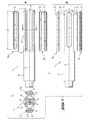
- a plug-in end 1 of a partially illustrated tool 2 has a circumferentially opposed self-lubricating elongated lubricant insert 3a (the back is shown rotated in the image plane), 3b, which is shown in FIG are each attached in an associated lubricant insert 4 in the metallic base 5 of the tool 2.
- the lubricant insert 3a which is adhesively bonded to the base body 5 by means of adhesive 8 in the associated lubricant insert recess 4, is made of porous sintered material as a carrier material and contains a dry lubricant in the form of graphite, which is incorporated in a finely divided manner in the carrier material.
- the lubricant insert 3a extends slightly beyond an axial groove length N of an axially extending rotational drive groove 6, which the lubricant insert 3a completely forms itself. Both lubricant inserts 3a, 3b are formed differently, wherein the lubricant insert 3a has exactly one rotary driving groove 6 and the lubricant insert 3b has exactly two rotary driving grooves 6.
- the elongate lubricant insert 3c is cup-shaped designed as a cylindrical portion and has in the elongated central region circumferentially on both sides each have a fastening clip 9 which is fixed in the base body 5 in an associated clip recess 7 which has circumferentially on both sides a tangential undercut 10.
- the entirety of the circumferentially opposite lubricant inserts 3c extends circumferentially over two-thirds of the total circumference of the insertion end 1 ', wherein both lubricant inserts 3c are identical and each have exactly one rotary driving groove 6.
Landscapes
- Engineering & Computer Science (AREA)
- Mechanical Engineering (AREA)
- Sliding-Contact Bearings (AREA)
- Percussive Tools And Related Accessories (AREA)
Abstract
Description
- Die Erfindung bezeichnet ein Einsteckende eines zumindest teilweise von einer Handwerkzeugmaschine schlagend angetriebenen Werkzeugs, insbesondere einen überwiegend aus Werkstoffstahl bestehenden Schlagbohrer oder einen Schlagmeissel mit radial eingeprägten Drehmitnahme- und Verriegelungsnuten.
- Sowohl das Werkzeug als auch die Werkzeugaufnahme unterliegen im Betrieb eines Bohr- bzw. Schlaghammers durch die Übertragung von Schlag und Drehmoment einer grossen Beanspuchung. Insbesondere beim Einsatz von Werkzeugen mit Durchmessern grösser 14 mm kommt es infolge der damit verbundenen hohen Drehmomentbelastung zu verstärktem Verschleiss und einer damit einhergehenden geringeren Standzeit von Einsteckende und Werkzeugaufnahme. Zur Verringerung des Verschleisses werden üblicherweise die zur Drehmomentübertragung verwendeten Mitnahmeflächen zwischen Werkzeugaufnahme und Einsteckende möglichst gross ausgebildet. Ziel ist es dabei, die Flächenbelastung und damit die Beanspruchung zu senken. Zudem ist es üblich, die dem Verschleiss unterliegenden Metallteile mit Methoden wie Borieren oder Härten verschleissfester auszubilden.
- Zumindest theoretisch kann der Verschleiss durch ein zusätzliches Einfetten eines sauberen Einsteckendes vor dem Einsetzen in die Werkzeugaufnahme wesentlich vermindert werden, praktisch erfolgt dies zumindest im Baugewerbe jedoch unzureichend. Zudem lagern sich an ungenutzten, eingefetteten Einsteckenden vermehrt Schmutzpartikel an, insbesondere in den Drehmitnahme- und Verriegelungsnuten, wodurch ein unsauberes, eingefettetes Einsteckende ebenfalls den Verschleiss erhöht.
- Nach der
DE19805187 erfolgt die Schmierung des Einsteckendes eines schlagend angetriebenen Werkzeugs über einen Schmiermittelvorrat in der Werkzeugaufnahme. - Nach der
DE9013190U ist bei einem aus Werkstoffstahl bestehenden einteiligen Einsteckende eine Flanke der Drehmitnahmenut konkav ausgebildet, um einen Kanal für die Verteilung des Schmiermittels auszubilden, welche in der Werkzeugaufnahme aufgetragen wird. - Nach der
EP1166933 ist ein aus Werkstoffstahl bestehendes, schlagend angetriebenes Werkzeug mit einem SDS-Einsteckende mit radial eingeprägten Drehmitnahme- und Verriegelungsnuten gesamthaft mit einer Oberflächenbeschichtung aus Molybdänsulfid, Graphit oder PTFE versehen, die im Bereich des Einsteckendes als Schmierstoff für eine Trockenschmierung wirken. Eine derartige dünne Oberflächenbeschichtung ist jedoch an den beanspruchten, verschleissbehafteten Mitnahmeflächen schnell abgenutzt und deren Schmiermittelinhalt für die Trockenschmierung deshalb bezüglich der Standzeit des Werkzeugs vorzeitig verbraucht. - Die Aufgabe der Erfindung besteht in der Realisierung eines Schlagwerkzeugeinsteckendes mit einer sich über die Standzeit des Werkzeugs erstreckenden Trockenschmierung.
- Die Aufgabe wird im Wesentlichen durch die Merkmale des Anspruchs 1 gelöst. Vorteilhafte Weiterbildungen ergeben sich aus den Unteransprüchen.
- So weist ein Einsteckende eines zumindest teilweise von einer Handwerkzeugmaschine schlagend antreibbaren Werkzeugs zumindest einen selbstschmierenden Schmierstoffeinsatz auf, welcher in einer zugeordneten Schmiereinsatzausnehmung im Grundkörper des Werkzeugs befestigt ist.
- Durch den im Einsteckende befestigten selbstschmierenden Schmierstoffeinsatz steht über die Standzeit des Werkzeugs eine ausreichende Schmierstoffmenge zur Verfügung.
- Vorteilhaft beinhaltet der Schmierstoffeinsatz ein Trockenschmiermittel, vorzugsweise Molybdänsulfid, Graphit oder PTFE, wodurch der bspw. mit dem feinverteilten Trockenschmiermittel getränkte Schmierstoffeinsatz selbst aus einem geeigneten porösen Trägermaterial herstellbar ist.
- Vorteilhaft besteht das poröse Trägermaterial aus einem Sinterwerkstoff, wodurch über dessen hohen Elastizitätsmodul auch bei hohen Betriebstemperaturen eine hinreichende Formstabilität gewährleistet ist.
- Alternativ besteht das poröse Trägermaterial aus einem hochtemperaturbeständigen Polymerwerkstoff, vorzugsweise Polyetheretherketon (PEEK), Polyoxymethylen (POM) oder Polyphenylensulfid (PPS), wodurch bspw. mittels Spritzguss eine ökonomische Herstellung der Schmierstoffeinsätze als Massenware möglich ist.
- Vorteilhaft ist der Schmierstoffeinsatz stoffschlüssig in der zugeordneten Schmiereinsatzausnehmung befestigt, wodurch mittels Kleben oder Löten eine grossflächig wirkende, technologisch einfache und ökonomisch effektive Befestigung nutzbar ist.
- Vorteilhaft ist der Schmierstoffeinsatz formschlüssig in der zugeordneten Schmiereinsatzausnehmung befestigt, wodurch auch bei einem mit Stosswellen mechanisch hoch beanspruchten Einsteckende eine dauerhafte Befestigung erzielt ist. Die formschlüssige Befestigung kann sowohl alternativ als auch zusätzlich zur stoffschlüssigen Befestigung erfolgen.
- Vorteilhaft ist der Schmierstoffeinsatz länglich ausgebildet, wodurch er optimal für eine eindimensionale Hin- und Herbewegung dimensioniert sowie längs einer Achse fixierbar ist.
- Vorteilhaft ist ein länglich ausgebildeter Schmierstoffeinsatz in einer axial verlaufenden Schmiereinsatzausnehmung angeordnet, wodurch er optimal für eine axial begrenzte Schlagbewegung des Einsteckendes dimensioniert ist.
- Vorteilhaft weist der Schmierstoffeinsatz zumindest einen quer zu seiner Längserstreckung auskragenden Befestigungsclip auf, weiter vorteilhaft im länglichen Mittelbereich, der in einer zugeordneten Clipausnehmung befestigt ist, wodurch insbesondere eine geeignete axiale Befestigung erfolgt.
- Vorteilhaft weist die Clipausnehmung einen Hinterschnitt auf, wodurch der mit einem zugeordneten Befestigungsclip versehene Schmierstoffeinsatz unverlierbar formschlüssig befestigt ist. Die Monatage des zugeordneten Schmierstoffeinsatzes mit dem Befestigungsclip in der hinterschnittenen Clipausnehmung erfolgt vorteilhaft unter Druckverspannung des Befestigungsclips.
- Vorteilhaft ist der längliche Schmierstoffeinsatz schalenförmig ausgebildet, weiter vorteilhaft als Zylinderabschnitt, wodurch eine grosse äussere selbstschmierende Oberfläche ausgebildet wird.
- Vorteilhaft weist der schalenförmige Schmierstoffeinsatz umfänglich beidseitig je einen Befestigungsclip auf, wodurch vermittelt über die Bauteilsteifigkeit des Schmierstoffeinsatzes ein Clip-Effekt erzielt wird, der die formschlüssige Fixierung der Befestigungsclips zusätzlich kraftschlüssig unterstützt und zudem die Montage vereinfacht.
- Vorteilhaft ersteckt sich der Schmierstoffeinsatz zumindest über eine axiale Nutenlänge einer axial verlaufenden Drehmitnahmenut, wodurch über den gesamten hochverschleissbeanspruchten Bereich der Drehmitnahmenut eine Selbstschmierung erfolgt.
- Vorteilhaft bildet der Schmierstoffeinsatz selbst eine Drehmitnahmenut aus, wodurch der hochverschleissbeanspruchte Bereich der Drehmitnahmenut optimal selbstgeschmiert ist.
- Vorteilhaft sind mehrere, weiter vorteilhaft zwei Schmierstoffeinsätze vorhanden, die jeweils in einer umfänglich verteilt, weiter vorteilhaft gleich verteilt, angeordneten Schmiereinsatzausnehmung angeordnet sind, wodurch die Selbstschmierung umfänglich verteilt erfolgt.
- Vorteilhaft erstreckt sich die Gesamtheit der Schmierstoffeinsätze umfänglich über mindestens die Hälfte, weiter vorteilhaft über zumindest zwei Drittel des Gesamtumfangs des Einsteckendes, wodurch der überwiegende Teil des Gesamtumfangs selbstgeschmiert ist.
- Vorteilhaft weist das Einsteckende genau zwei, gegenüberliegende Schmierstoffeinsätze auf, die jeweils genau eine Drehmitnahmenut aufweisen, wodurch über nur zwei verschiedene Bauteile ein marktübliches Einsteckende (oft als T- oder SDS-Einsteckende bezeichnet) dreiteilig ausgebildet wird.
- Vorteilhaft sind zumindest zwei Schmierstoffeinsätze mit unterschiedlich ausgebildeten und/oder angeordneten Drehmitnahmenuten vorhanden, wodurch unsymmetrische Symmetrien einfach realisierbar sind. So ist es bspw. technologisch einfach möglich, mit ein und demselben aus Werkstoffstahl bestehenden Grundkörper durch modulare Kombination mit verschiedenen Schmierstoffeinsätzen geometrisch unterschiedliche Einsteckenden herzustellen, die in bestimmten Anwendungsbereichen bzw. Märkten benötigt werden.
- Vorteilhaft weist das Einsteckende genau zwei, gegenüberliegende Schmierstoffeinsätze auf, wobei der erste Schmierstoffeinsatz genau eine Drehmitnahmenut aufweist und der zweite Schmierstoffeinsatz genau zwei Drehmitnahmenuten aufweist, wodurch ein für Durchmesser grösser 14 mm marktübliches Einsteckende (oft als Y- oder SDS Max - Einsteckende bezeichnet) dreiteilig ausgebildet wird.
- Vorteilhaft ist bei einem Set von Werkzeugen mit verschiedenen Einsteckenden mit Schmiermitteleinsätzen der Grundkörper identisch ausgebildet, wodurch bei der Herstellung die Anzahl unterschiedlicher Bauteile reduziert ist.
- Die Erfindung wird bezüglich eines vorteilhaften Ausführungsbeispiels näher erläutert mit:
- Fig. 1 als Einsteckende in drei Explosionsdarstellungen mit verschiedenen Ansichtsgruppen a und b
- Fig. 2 als Variante in drei Explosionsdarstellungen mit verschiedenen Ansichtsgruppen a und b
- Nach Fig. 1 weist ein zum schlagenden Antrieb durch eine Handwerkzeugmaschine längs der Achse A geeignet ausgestaltetes Einsteckende 1 eines nur teilweise dargestellten Werkzeugs 2 zwei umfänglich gegenüberliegende selbstschmierende, länglich ausgebildete Schmierstoffeinsätze 3a (das rückseitige ist in der Bildebene gedreht dargestellt), 3b auf, welche in je einer zugeordneten Schmierstoffeinsatzausnehmung 4 im metallischen Grundkörper 5 des Werkzeugs 2 befestigt sind. Der in der zugeordneten Schmierstoffeinsatzausnehmung 4 mittels Klebstoff 8 stoffschlüssig mit dem Grundkörper 5 verbundene Schmierstoffeinsatz 3a besteht als Trägermaterial aus porösen Sinterwerkstoff und beinhaltet ein Trockenschmiermittel in Form von Graphit, das im Trägermaterial feinverteilt eingelagert ist. Der Schmierstoffeinsatz 3a ersteckt sich etwas über eine axiale Nutenlänge N einer axial verlaufenden Drehmitnahmenut 6 hinaus, welche der Schmierstoffeinsatz 3a vollständig selbst ausbildet. Beide Schmierstoffeinsätze 3a, 3b sind unterschiedlich ausgebildet, wobei der Schmierstoffeinsatz 3a genau eine Drehmitnahmenut 6 und der Schmierstoffeinsatz 3b genau zwei Drehmitnahmenuten 6 aufweist.
- Nach Fig. 2 weist ein alternatives zum schlagenden Antrieb durch eine Handwerkzeugmaschine längs der Achse A geeignet ausgestaltetes Einsteckende 1' eines nur teilweise dargestellten Werkzeugs 2 einen selbstschmierenden Schmierstoffeinsatz 3c (das rückseitige ist in der Bildebene gedreht dargestellt) auf, welcher formschlüssig in einer zugeordneten Schmierstoffeinsatzausnehmung 4 im metallischen Grundkörper 5 des Werkzeugs 2 befestigt ist. Das poröse Trägermaterial des Schmierstoffeinsatz 3c besteht aus einem hochtemperaturbeständigen Polymerwerkstoff in Form von PEEK. Der längliche Schmierstoffeinsatz 3c ist schalenförmig als Zylinderabschnitt ausgebildet und weist im länglichen Mittelbereich umfänglich beidseitig je einen Befestigungsclip 9 auf, der im Grundkörper 5 in einer zugeordneten Clipausnehmung 7 befestigt ist, die umfänglich beidseitig einen tangentialen Hinterschnitt 10 aufweist. Die Gesamtheit der umfänglich gegenüberliegenden Schmierstoffeinsätze 3c erstreckt sich umfänglich über zwei Drittel des Gesamtumfangs des Einsteckendes 1', wobei beide Schmierstoffeinsätze 3c identisch sind und jeweils genau eine Drehmitnahmenut 6 aufweisen.
- Bis auf die für die wählfrei kombinierbare Art der Befestigung als stoffschlüssig, formschlüssig oder beides benötigten Merkmale 7, 8, 9, 10 ist bei einem Set von Werkzeugen 2 nach den Fig. 1 und Fig. 2 mit verschiedenen Einsteckenden 1, 1' mit Schmierstoffeinsätzen 3a, 3b bzw. 3c der Grundkörper 5 identisch ausgebildet.
Claims (20)
Applications Claiming Priority (1)
| Application Number | Priority Date | Filing Date | Title |
|---|---|---|---|
| DE200510038089 DE102005038089A1 (de) | 2005-08-11 | 2005-08-11 | Einsteckende |
Publications (3)
| Publication Number | Publication Date |
|---|---|
| EP1752258A2 true EP1752258A2 (de) | 2007-02-14 |
| EP1752258A3 EP1752258A3 (de) | 2010-07-07 |
| EP1752258B1 EP1752258B1 (de) | 2012-04-04 |
Family
ID=37440694
Family Applications (1)
| Application Number | Title | Priority Date | Filing Date |
|---|---|---|---|
| EP20060118239 Active EP1752258B1 (de) | 2005-08-11 | 2006-08-01 | Werkzeug mit einem Einsteckende |
Country Status (2)
| Country | Link |
|---|---|
| EP (1) | EP1752258B1 (de) |
| DE (1) | DE102005038089A1 (de) |
Cited By (1)
| Publication number | Priority date | Publication date | Assignee | Title |
|---|---|---|---|---|
| EP3925735A1 (de) * | 2020-06-17 | 2021-12-22 | Hilti Aktiengesellschaft | Werkzeug und system |
Family Cites Families (3)
| Publication number | Priority date | Publication date | Assignee | Title |
|---|---|---|---|---|
| US1959516A (en) * | 1930-08-28 | 1934-05-22 | Black & Decker Mfg Co | Hammer |
| DE19805187B4 (de) * | 1998-02-10 | 2006-03-16 | Robert Bosch Gmbh | Handwerkzeugmaschine, insbesondere Bohr- bzw. Schlaghammer |
| DE20010774U1 (de) * | 2000-06-16 | 2000-09-14 | RECA NORM GmbH & Co KG, 74635 Kupferzell | Bohrer mit Beschichtung |
-
2005
- 2005-08-11 DE DE200510038089 patent/DE102005038089A1/de not_active Withdrawn
-
2006
- 2006-08-01 EP EP20060118239 patent/EP1752258B1/de active Active
Cited By (2)
| Publication number | Priority date | Publication date | Assignee | Title |
|---|---|---|---|---|
| EP3925735A1 (de) * | 2020-06-17 | 2021-12-22 | Hilti Aktiengesellschaft | Werkzeug und system |
| WO2021254827A1 (de) * | 2020-06-17 | 2021-12-23 | Hilti Aktiengesellschaft | Werkzeug und system |
Also Published As
| Publication number | Publication date |
|---|---|
| EP1752258A3 (de) | 2010-07-07 |
| EP1752258B1 (de) | 2012-04-04 |
| DE102005038089A1 (de) | 2007-02-15 |
Similar Documents
| Publication | Publication Date | Title |
|---|---|---|
| DE69007983T2 (de) | Lagerbuchse. | |
| DE102015201248B3 (de) | Gleitlageranordnung eines Drehelements auf einem Lagerbolzen, insbesondere eines Planetenrades auf einem Planetenradbolzen eines Planetenradgetriebes | |
| EP1584389B1 (de) | Dehnspanneinrichtung | |
| EP3612743B1 (de) | Getriebeanordnung mit axialen kippsegmenten | |
| DE102015113312A1 (de) | Drehwerkzeug | |
| EP1267033A1 (de) | Gesteinsbohrwerkzeug | |
| WO2007031285A1 (de) | Vorrichtung zur lösbaren kupplung zweier bauteile | |
| EP1752258B1 (de) | Werkzeug mit einem Einsteckende | |
| DE102013211788B4 (de) | Wellenlagerungsvorrichtung | |
| EP1096045B1 (de) | Lagerung für einen Offenend-Spinnrotor | |
| DE112008000851B4 (de) | Dichtteil für eine Wälzvorrichtung und Wälzvorrichtung | |
| DE102012207518A1 (de) | Hebelartiger Nockenfolger | |
| EP1631733A1 (de) | Halteelement für ein rundschaftmeissel einer fräsvorrichtung | |
| EP3412244A1 (de) | Dentales hand- oder winkelstück mit einem rotierenden werkzeug | |
| DE102005001536B3 (de) | Werkzeug für eine Schrämmaschine | |
| DE102005033356A1 (de) | Radialwälzlager, insbesondere zur Lagerung gering belasteter Wellen in Schwermaschinen | |
| EP1354143A1 (de) | Gleitlager | |
| DE202005005829U1 (de) | Gelenklager | |
| DE102008032328A1 (de) | Wälzlager mit einem Schmierungssystem | |
| DE102009008365B4 (de) | Kolbenpumpe, insbesondere Kraftstoffpumpe für ein Einspritzsystem, mit einer Keramikplatte als Verschleißschutz | |
| DE102006043733A1 (de) | Vorrichtung zur lösbaren Kupplung zweier Bauteile | |
| EP4424467A1 (de) | Elektrowerkzeug | |
| DD253347A3 (de) | Vorrichtung zum kuehlen und schmieren rotierender schneidwerkzeuge | |
| DE102015005366B4 (de) | Wellenanordnung, Lageranordnung mit einer Wellenanordnung sowie Verfahren zum Montieren einer Lageranordnung | |
| EP2045039A1 (de) | Schleif- oder Polierscheibe mit Gewindeeinsatz |
Legal Events
| Date | Code | Title | Description |
|---|---|---|---|
| PUAI | Public reference made under article 153(3) epc to a published international application that has entered the european phase |
Free format text: ORIGINAL CODE: 0009012 |
|
| AK | Designated contracting states |
Kind code of ref document: A2 Designated state(s): AT BE BG CH CY CZ DE DK EE ES FI FR GB GR HU IE IS IT LI LT LU LV MC NL PL PT RO SE SI SK TR |
|
| AX | Request for extension of the european patent |
Extension state: AL BA HR MK YU |
|
| PUAL | Search report despatched |
Free format text: ORIGINAL CODE: 0009013 |
|
| AK | Designated contracting states |
Kind code of ref document: A3 Designated state(s): AT BE BG CH CY CZ DE DK EE ES FI FR GB GR HU IE IS IT LI LT LU LV MC NL PL PT RO SE SI SK TR |
|
| AX | Request for extension of the european patent |
Extension state: AL BA HR MK RS |
|
| 17P | Request for examination filed |
Effective date: 20110107 |
|
| AKX | Designation fees paid |
Designated state(s): CH DE FR GB LI |
|
| GRAP | Despatch of communication of intention to grant a patent |
Free format text: ORIGINAL CODE: EPIDOSNIGR1 |
|
| GRAS | Grant fee paid |
Free format text: ORIGINAL CODE: EPIDOSNIGR3 |
|
| GRAA | (expected) grant |
Free format text: ORIGINAL CODE: 0009210 |
|
| AK | Designated contracting states |
Kind code of ref document: B1 Designated state(s): CH DE FR GB LI |
|
| REG | Reference to a national code |
Ref country code: GB Ref legal event code: FG4D Free format text: NOT ENGLISH |
|
| REG | Reference to a national code |
Ref country code: CH Ref legal event code: EP |
|
| REG | Reference to a national code |
Ref country code: DE Ref legal event code: R096 Ref document number: 502006011234 Country of ref document: DE Effective date: 20120531 |
|
| PLBE | No opposition filed within time limit |
Free format text: ORIGINAL CODE: 0009261 |
|
| STAA | Information on the status of an ep patent application or granted ep patent |
Free format text: STATUS: NO OPPOSITION FILED WITHIN TIME LIMIT |
|
| 26N | No opposition filed |
Effective date: 20130107 |
|
| REG | Reference to a national code |
Ref country code: DE Ref legal event code: R097 Ref document number: 502006011234 Country of ref document: DE Effective date: 20130107 |
|
| REG | Reference to a national code |
Ref country code: FR Ref legal event code: PLFP Year of fee payment: 11 |
|
| REG | Reference to a national code |
Ref country code: FR Ref legal event code: PLFP Year of fee payment: 12 |
|
| REG | Reference to a national code |
Ref country code: FR Ref legal event code: PLFP Year of fee payment: 13 |
|
| PGFP | Annual fee paid to national office [announced via postgrant information from national office to epo] |
Ref country code: GB Payment date: 20220822 Year of fee payment: 17 Ref country code: DE Payment date: 20220819 Year of fee payment: 17 |
|
| PGFP | Annual fee paid to national office [announced via postgrant information from national office to epo] |
Ref country code: FR Payment date: 20220823 Year of fee payment: 17 |
|
| PGFP | Annual fee paid to national office [announced via postgrant information from national office to epo] |
Ref country code: CH Payment date: 20220824 Year of fee payment: 17 |
|
| P01 | Opt-out of the competence of the unified patent court (upc) registered |
Effective date: 20230830 |
|
| REG | Reference to a national code |
Ref country code: DE Ref legal event code: R119 Ref document number: 502006011234 Country of ref document: DE |
|
| REG | Reference to a national code |
Ref country code: CH Ref legal event code: PL |
|
| GBPC | Gb: european patent ceased through non-payment of renewal fee |
Effective date: 20230801 |
|
| PG25 | Lapsed in a contracting state [announced via postgrant information from national office to epo] |
Ref country code: CH Free format text: LAPSE BECAUSE OF NON-PAYMENT OF DUE FEES Effective date: 20230831 |
|
| PG25 | Lapsed in a contracting state [announced via postgrant information from national office to epo] |
Ref country code: GB Free format text: LAPSE BECAUSE OF NON-PAYMENT OF DUE FEES Effective date: 20230801 |
|
| PG25 | Lapsed in a contracting state [announced via postgrant information from national office to epo] |
Ref country code: GB Free format text: LAPSE BECAUSE OF NON-PAYMENT OF DUE FEES Effective date: 20230801 Ref country code: FR Free format text: LAPSE BECAUSE OF NON-PAYMENT OF DUE FEES Effective date: 20230831 Ref country code: DE Free format text: LAPSE BECAUSE OF NON-PAYMENT OF DUE FEES Effective date: 20240301 |