EP1751038B1 - Assembly for hingedly coupling parts of a conveyor - Google Patents
Assembly for hingedly coupling parts of a conveyor Download PDFInfo
- Publication number
- EP1751038B1 EP1751038B1 EP05749414A EP05749414A EP1751038B1 EP 1751038 B1 EP1751038 B1 EP 1751038B1 EP 05749414 A EP05749414 A EP 05749414A EP 05749414 A EP05749414 A EP 05749414A EP 1751038 B1 EP1751038 B1 EP 1751038B1
- Authority
- EP
- European Patent Office
- Prior art keywords
- hinge
- assembly
- eye
- conveyor
- row
- Prior art date
- Legal status (The legal status is an assumption and is not a legal conclusion. Google has not performed a legal analysis and makes no representation as to the accuracy of the status listed.)
- Active
Links
- 230000008878 coupling Effects 0.000 title claims abstract description 11
- 238000010168 coupling process Methods 0.000 title claims abstract description 11
- 238000005859 coupling reaction Methods 0.000 title claims abstract description 11
- 210000003128 head Anatomy 0.000 claims abstract description 48
- 230000005012 migration Effects 0.000 description 3
- 238000013508 migration Methods 0.000 description 3
- 238000005452 bending Methods 0.000 description 2
- 238000004026 adhesive bonding Methods 0.000 description 1
- 230000000712 assembly Effects 0.000 description 1
- 238000000429 assembly Methods 0.000 description 1
- 239000011324 bead Substances 0.000 description 1
- 239000011449 brick Substances 0.000 description 1
- 210000000080 chela (arthropods) Anatomy 0.000 description 1
- 238000011109 contamination Methods 0.000 description 1
- 238000001125 extrusion Methods 0.000 description 1
- 230000002349 favourable effect Effects 0.000 description 1
- 238000001746 injection moulding Methods 0.000 description 1
- 230000002452 interceptive effect Effects 0.000 description 1
- 239000000463 material Substances 0.000 description 1
- 230000008018 melting Effects 0.000 description 1
- 238000002844 melting Methods 0.000 description 1
- 239000002184 metal Substances 0.000 description 1
- 239000004033 plastic Substances 0.000 description 1
- 230000009467 reduction Effects 0.000 description 1
- 239000012815 thermoplastic material Substances 0.000 description 1
- 230000008719 thickening Effects 0.000 description 1
- 238000003466 welding Methods 0.000 description 1
Images


Classifications
-
- B—PERFORMING OPERATIONS; TRANSPORTING
- B65—CONVEYING; PACKING; STORING; HANDLING THIN OR FILAMENTARY MATERIAL
- B65G—TRANSPORT OR STORAGE DEVICES, e.g. CONVEYORS FOR LOADING OR TIPPING, SHOP CONVEYOR SYSTEMS OR PNEUMATIC TUBE CONVEYORS
- B65G17/00—Conveyors having an endless traction element, e.g. a chain, transmitting movement to a continuous or substantially-continuous load-carrying surface or to a series of individual load-carriers; Endless-chain conveyors in which the chains form the load-carrying surface
- B65G17/30—Details; Auxiliary devices
- B65G17/38—Chains or like traction elements; Connections between traction elements and load-carriers
- B65G17/40—Chains acting as load-carriers
-
- B—PERFORMING OPERATIONS; TRANSPORTING
- B65—CONVEYING; PACKING; STORING; HANDLING THIN OR FILAMENTARY MATERIAL
- B65G—TRANSPORT OR STORAGE DEVICES, e.g. CONVEYORS FOR LOADING OR TIPPING, SHOP CONVEYOR SYSTEMS OR PNEUMATIC TUBE CONVEYORS
- B65G17/00—Conveyors having an endless traction element, e.g. a chain, transmitting movement to a continuous or substantially-continuous load-carrying surface or to a series of individual load-carriers; Endless-chain conveyors in which the chains form the load-carrying surface
- B65G17/06—Conveyors having an endless traction element, e.g. a chain, transmitting movement to a continuous or substantially-continuous load-carrying surface or to a series of individual load-carriers; Endless-chain conveyors in which the chains form the load-carrying surface having a load-carrying surface formed by a series of interconnected, e.g. longitudinal, links, plates, or platforms
- B65G17/08—Conveyors having an endless traction element, e.g. a chain, transmitting movement to a continuous or substantially-continuous load-carrying surface or to a series of individual load-carriers; Endless-chain conveyors in which the chains form the load-carrying surface having a load-carrying surface formed by a series of interconnected, e.g. longitudinal, links, plates, or platforms the surface being formed by the traction element
-
- B—PERFORMING OPERATIONS; TRANSPORTING
- B65—CONVEYING; PACKING; STORING; HANDLING THIN OR FILAMENTARY MATERIAL
- B65G—TRANSPORT OR STORAGE DEVICES, e.g. CONVEYORS FOR LOADING OR TIPPING, SHOP CONVEYOR SYSTEMS OR PNEUMATIC TUBE CONVEYORS
- B65G2207/00—Indexing codes relating to constructional details, configuration and additional features of a handling device, e.g. Conveyors
- B65G2207/12—Chain pin retainers
Definitions
- the invention relates to an assembly for hingedly coupling parts of a conveyor, and to a hinge pin.
- a conveyor such as a conveyor mat or chain built up from modules, or a conveyor belt composed of one or more segments
- conveyor parts are coupled with the aid of hinge pins.
- a problem that occurs therein is that the hinge pins need to be locked against axial migration.
- a very advantageous assembly is known from EP 0 787 663 , which describes an assembly according to the preamble of claim 1.
- a pin with a thickened head is introduced into an end hinge eye which is somewhat out of alignment with respect to the other hinge eyes.
- pin and/or module After passing the enlarged hinge hole, pin and/or module return to their original form and the pin is axially locked between, on the one side, a locking surface of the end hinge eye in alignment with the other hinge eyes and, on the other side, the next hinge eye in coupled condition.
- a further drawback of the known conveyor is that the pin cannot extend to the side edge of the conveyor. Thus, a part of the width of the conveyor remains unused for transmitting tensile forces between the conveyor parts via the hinge pin.
- the invention contemplates an assembly for hingedly coupling parts of a conveyor with which, while maintaining the advantages, these drawbacks can be obviated.
- the invention provides an assembly for hingedly coupling parts of a conveyor, comprising a first conveyor part provided with a first row of hinge eyes spaced apart from one another with mutual interspaces with an end hinge eye located along a longitudinal edge of the conveyor part, with an end hinge hole which is somewhat out of alignment with respect to an adjacent hinge hole from the first row, further comprising a second conveyor part provided with a second row of hinge eyes which are also spaced apart from one another with mutual interspaces, such that the conveyor parts can cooperate in a coupled condition by receiving hinge eyes in corresponding interspaces, and a hinge pin provided with a central body part which extends, in coupled condition of the assembly, through hinge holes of the first row and of the second row, further provided with a thickened head which is able to pass the end hinge hole of the end hinge eye, but not the hinge hole of the next hinge eye in coupled condition, which thickened head is, in coupled condition, axially locked between the end hinge eye and the next hinge eye, characterized in that the thickened head bears a substantially cylindrical
- the hinge pin can be engaged via the end hinge eye, so that the pin is accessible from the side of the conveyor in order to be detached. This cannot only facilitate the detachment, but also allows a closed design of the conveying surface of the conveyor. Further, in coupled condition, the projection can abut a part of the wall of the end hinge eye, so that the whole width of the conveyor can be used for transmitting tensile forces.
- EP 1 500 614 which falls under Article 54(3) EPC, discloses an assembly for hingedly coupling parts of a conveyor from which the subject-matter of the present invention differs in that the diameter of the projection is constant and smaller than the diameter of the thickened head.
- US 5 645 160 discloses in Fig. 7 a hinge with a thickened head and a projection.
- US 3 726 569 discloses in Fig. 3 an insert having a wedge shaped flange.
- an assembly 1 for hingedly coupling parts of a conveyor.
- the assembly comprises a first conveying part 2, a second conveying part 3 and a hinge pin 4.
- the first conveying part 2 and the second conveying part 3 are designed as successive modules of a modular conveyor mat.
- Such a conveyor mat is generally known and is usually built up from rows of one or more modules extending transverse to a conveying direction indicated by an arrow P, while rows of modules successive in conveying direction are often included in a mat so as to be staggered with respect to one another according to a brick pattern and the mat is often designed as an endless belt.
- the first conveying part 2 is provided with a first row 5 with hinge eyes 7 spaced apart with mutual interspaces 6.
- the first row 5 comprises a sub-row 5A with more centrally located hinge eyes 7A.
- the more centrally located hinge eyes 7A of the sub-row 5A are provided with hinge holes 8A in alignment with respect to one another.
- the hinge eyes 7 have identical designs and the mutual interspaces 6 between the hinge eyes 7 are equal.
- the hinge holes 8A have a substantially cylindrical design along a common centerline H 1 and have substantially the same diameter.
- the shapes of the different hinge eyes 7 and/or their mutual interspaces 6 may be unequal, and that the shapes and the dimensions of the hinge holes 8A of the successive hinge eyes may vary or may at least be chosen differently than shown in the Figure.
- the first row 5 of hinge eyes 7 further comprises an end hinge eye 7B adjacent to the sub-row 5A, which end hinge eye 7B is located on the longitudinal edge of the conveyor 1.
- the end hinge eye 7B is provided with an enlarged hinge hole 8B which is positioned somewhat out of alignment.
- the hinge hole 8B with the enlarged design has a cylindrical design with a larger diameter than the other hinge holes 8A from the first row.
- the centerline H 2 of the enlarged hinge hole 8B is located at the same height as the centerline H 1 of the hinge holes 8A, but extends parallel to the centerline H 1 through the hinge holes 8A, shifted in conveying direction over a distance E.
- the end hinge hole 7B is provided with a locking surface 20 which is adjacent to the enlarged hinge hole 8B and extends onto the line.
- the notion "positioned in alignment” is to be understood to mean that, transverse to the conveying direction, successive hinge holes can be aligned to let a hinge pin pass freely in extended condition and that "somewhat positioned in alignment” is to be understood to mean that such a hole cannot be passed without deformation of the hinge pin and/or at least one of the conveying parts. Such a passage without deformation is then prevented in that the body part of the hinge eye surrounding the non-aligned hinge hole extends onto the line of free passage of the hinge pin.
- these notions are very well defined by the wording that the end hinge eye is in partial registry with the hinge eyes of the sub-row, and that the hinge pin is in interfering alignment with the hinge eye of the non-aligned hinge hole.
- the second conveyor part 3 is provided with a second row 9 of hinge eyes 10 which are spaced apart with mutual interspaces 11 and which are provided with hinge holes 12 aligned with respect to one another.
- the hinge eyes 10, the interspaces 11 and the hinge holes 12 are identical to the hinge eyes 7A, the interspaces 6 and the hinge holes 8A of the first conveyor part 2. So, the hinge holes 12 of the hinge eyes 10 also have a cylindrical design and are on a common centerline H 3 .
- the conveying parts 2, 3 can cooperate in coupled condition in that hinge eyes 7 of a module designed as a first conveying part, which extend in a conveying direction indicated by the open part of arrow P and reach forwards, are included in interspaces 11 between hinge eyes 10 reaching backwards of the second conveying part 3 succeeding in conveying direction and designed as a similar module.
- hinge eyes 10 of the second row are included in interspaces 6 between the hinge eyes of the first row 5.
- the hinge pin 4 is provided with a central body part 15.
- the central body part 15 extends through the hinge holes 8A of the hinge eyes 7A of sub-row 5A and through the hinge holes 13 of the hinge eyes 10 of the second row 9, such that the centerline of the hinge pin H 4 runs substantially parallel between the centerlines H 1 and H 3 of the hinge holes 8A, 12 of the cooperating hinge eyes 7A, 10.
- the hinge pin 4 is provided with a thickened head 16 which is able to pass the enlarged end hinge hole 8B of the end hinge eye 7B, but is not able to pass the next hinge eye in coupled condition.
- the hinge pin 4 is thus axially locked between the locking surface 20 of the end hinge eye 7B on the one side and the next hinge eye 14 in coupled condition, herein formed by the hinge eye 10 bounding the second row 19, on the other side.
- the thickened head 16 forms a part of the pin 4 with a larger diameter than the body part 15 of the pin 4 and has a conical design in this exemplary embodiment. As a result, at the location of the thickened head 16, the pin 4 has an enlarged diameter.
- the head 16 tapers towards the central part.
- the outer surface 17 of the cone cooperates with a corresponding cone stop surface 18 which is recessed in the hinge eye 14.
- an end surface 21 of the thickened head 16 cooperates with the locking surface 20, so that the hinge pin 4 is locked against axial migration.
- the thickened head 16 bears a projection 19 designed with a smaller diameter compared to the head, which projection 19 extends into the hinge hole 8B of the end hinge eye 7B in coupled condition.
- the projection 19 is narrowed compared to the head 16 and reaches axially outwards from the head 16 in a direction away from the body part 15.
- the projection 19 is substantially cylindrical and has the same diameter as the body part 15 of the hinge pin 4.
- the projection 19 extends collinear with the central body part 15 of the hinge pin 4. In this manner, a part of the outer surface of the projection 19 abuts the wall of the enlarged hole 8B in the end hinge eye 7B, so that the end hinge eye 7B can also be used for transmitting tensile force.
- the hinge pin 4 extends over the whole width of the conveyor 1.
- the thickened head may of course have a different shape, for instance a sphere, a cylinder or a block shape.
- the conical shape shown in the exemplary embodiment is preferred because it can easily be introduced and further offers a good extent of locking.
- FIGs. 5-7 show that the pin 4 can be introduced in the direction indicated by the arrow Q transverse to the conveying direction.
- the central body part 15 can be threaded through the hinge holes 8, 12 up to the thickened head without bending of the pin 4.
- the pin 4 Upon reaching the thickened head 16, the pin 4 will bend slightly outwards and sidewards at the location of the head 16 ( Fig. 5 ).
- the thickened head 16 can just pass the enlarged hinge hole 8B, which is somewhat staggered.
- the pin 4 will spring back again and the thickened head 16 is locked as shown in Fig. 6 .
- the thickened head 16 In coupled condition, the thickened head 16 is thus located between the end hinge eye 7B and the next hinge eye 14. With the aid of its thickened head 16, the hinge pin 4 is locked in a first axial direction between the locking surface 20 of the end hinge eye 7B which cooperates with the end surface 21 of the thickened head 16. In opposite axial direction, the hinge eye is locked in that the conical outer surface 17 of the thickened head 16 cooperates with the cone stop surface 18 of the hinge eye 14.
- Detaching the pin 4 can be carried out by engaging the projection 19 of the pin 4 with the aid of a pair of pincers at the location of the longitudinal edge of the conveyor 1 and, after bending of the pin 4, pulling the thickened head 16 out via the large hole 8B of the end hinge eye 7B. Then the pin can spring back and be pulled back in extended condition.
- Fig. 3 shows that the diameter D2 of the hole in the end hinge eye is larger than the diameter D1 of the other hinge eyes. It further shows that the centerline H 2 of the hole 8B of the end hinge eye 7B is shifted over a distance E parallel to the conveying surface T.
- the hinge pin 4 is preferably designed from plastic, preferably from thermoplastic material by means of injection molding or extrusion.
- the thickened head may for instance be formed by upsetting the pin, but may also be molded integrally therewith. It is further possible to form the thickening with the aid of a separate part, such as for instance a bead, which is connected with the pin, for instance by gluing, welding or melting.
- the thickened part 16 may for instance be designed from a different type of material, for instance from metal and may optionally have a thin-walled design.
- the pin 4 can be retrieved from the side of the conveyor 1 without any special tools.
- the conveying surface T of the conveyor 1 formed by the top surfaces of the conveying parts 2, 3 can have a substantially closed design and recesses in the conveying surface for making the thickened head 16 accessible can be avoided.
- the end hinge eye 7B can partly be reduced.
- the locking surface 20' interrupted by the reduction surrounds the end hinge hole 8B as an interrupted ring segment radially contiguous with the hinge hole 8B.
- the end hinge eye 7B is still further reduced so that it is designed as a stop cam 7B" reaching outwards with respect to the body part 15 of the conveying part 2, leaving a space corresponding with the end hinge hole 8B clear.
- the stop cam 7B" carries the locking surface 20".
- the space corresponding with the end hinge hole 8B can be positioned in alignment with the other hinge holes 8A.
- the hinge pin 4 is locked against axial migration in that, with the aid of its thickened head 16, it is axially locked between the locking surface 20 cooperating with the end surface 21 of the thickened head 16 on the one side and the stop surface 18 of the next hinge eye 14 in coupled condition of the conveying parts 2, 3, which coincides with the outer surface 17 of the thickened head on the other side.
- the conveyor parts may also be designed as chain modules of a modular conveyor chain.
- the first and second conveyor parts may form ends of one conveyor mat segment which is coupled into an endless belt or the first and second conveying parts may form the beginning and the end of intercoupled conveyor belt segments, respectively.
- multiple pins may be provided, for instance a relatively short locking pin with thickened head on a longitudinal edge and one or more longer, cylindrical additional pins. In this manner, a conventional locking pin can relatively simply be deployed for conveyors of different widths.
Landscapes
- Engineering & Computer Science (AREA)
- Mechanical Engineering (AREA)
- Chain Conveyers (AREA)
- Automobile Manufacture Line, Endless Track Vehicle, Trailer (AREA)
Abstract
Description
- The invention relates to an assembly for hingedly coupling parts of a conveyor, and to a hinge pin. With hingedly coupling parts of a conveyor, such as a conveyor mat or chain built up from modules, or a conveyor belt composed of one or more segments, conveyor parts are coupled with the aid of hinge pins. A problem that occurs therein is that the hinge pins need to be locked against axial migration.
- In the prior art, many assemblies have already been proposed for this, such as plugs, detachable clips, non-detachable clips, integrated snap fingers, pins cooperating with stops and pins with thickened heads.
- A very advantageous assembly is known from
EP 0 787 663 , which describes an assembly according to the preamble ofclaim 1. In this assembly, with deformation of at least one of the conveyor parts to be coupled and/or the hinge pin, via an enlarged hinge hole, a pin with a thickened head is introduced into an end hinge eye which is somewhat out of alignment with respect to the other hinge eyes. After passing the enlarged hinge hole, pin and/or module return to their original form and the pin is axially locked between, on the one side, a locking surface of the end hinge eye in alignment with the other hinge eyes and, on the other side, the next hinge eye in coupled condition. - Due to the absence of separate parts and due to its good cleanability, this assembly is well suitable for conveyors in the food industry.
- What is disadvantageous about the known assembly, however, is that it is difficult to detach after coupling. In order to enable a good detachability, an opening is provided in the conveying surface formed by the conveying parts, so that the thickened head is accessible from above to be engaged and to be slid out with deformation of the pin and/or the modules. This opening interferes with the possibility to design the conveying surface of the conveyor so as to be closed. The opening is then less favorable with a view to cleanability of the conveyor, since such an opening can locally cause contaminations.
- A further drawback of the known conveyor is that the pin cannot extend to the side edge of the conveyor. Thus, a part of the width of the conveyor remains unused for transmitting tensile forces between the conveyor parts via the hinge pin. The invention contemplates an assembly for hingedly coupling parts of a conveyor with which, while maintaining the advantages, these drawbacks can be obviated. To this end, the invention provides an assembly for hingedly coupling parts of a conveyor, comprising
a first conveyor part provided with a first row of hinge eyes spaced apart from one another with mutual interspaces with an end hinge eye located along a longitudinal edge of the conveyor part, with an end hinge hole which is somewhat out of alignment with respect to an adjacent hinge hole from the first row, further comprising
a second conveyor part provided with a second row of hinge eyes which are also spaced apart from one another with mutual interspaces, such that the conveyor parts can cooperate in a coupled condition by receiving hinge eyes in corresponding interspaces, and
a hinge pin provided with a central body part which extends, in coupled condition of the assembly, through hinge holes of the first row and of the second row, further provided with a thickened head which is able to pass the end hinge hole of the end hinge eye, but not the hinge hole of the next hinge eye in coupled condition, which thickened head is, in coupled condition, axially locked between the end hinge eye and the next hinge eye, characterized in that the thickened head bears a substantially cylindrical projection with a smaller diameter compared to the head which reaches into the hinge hole of the end hinge eye in coupled condition, the projection (19) being a cylindrical end projection of which the diameter is constant and smaller than the diameter of the thickened head. By using the projection, it is realized that the hinge pin can be engaged via the end hinge eye, so that the pin is accessible from the side of the conveyor in order to be detached. This cannot only facilitate the detachment, but also allows a closed design of the conveying surface of the conveyor. Further, in coupled condition, the projection can abut a part of the wall of the end hinge eye, so that the whole width of the conveyor can be used for transmitting tensile forces. -
EP 1 500 614 -
US 5 645 160 discloses inFig. 7 a hinge with a thickened head and a projection. -
US 3 726 569 discloses inFig. 3 an insert having a wedge shaped flange. - Further advantageous embodiments of the invention are disclosed in the subclaims.
- The invention will be elucidated in more detail with reference to an exemplary embodiment shown in the drawing, in which:
-
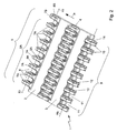
Fig. 1 shows a schematic perspective top plan view of two hingedly coupled conveying parts of a conveyor; -
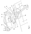
Fig. 2 shows a schematic perspective bottom view of the two hingedly coupled conveying parts ofFig. 1 ; -
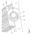
Fig. 3 shows a detail of the end of the conveying parts ofFig. 2 at a different angle in partial cross section; -
Figs. 4-6 each show a schematic perspective bottom view in detail of two conveying parts during successive steps of coupling with the hinge pin; -
Fig. 7 shows a schematic perspective view of a first variant of an alternative embodiment of a conveying part in which the end hinge eye is partly reduced; and -
Fig. 8 shows a schematic perspective view of a second variant of an alternative embodiment in which the end hinge eye is designed as a stop cam. - The Figures are only schematic representations of a preferred embodiment of the invention given by way of non-limitative exemplary embodiment. In the drawing, corresponding or same parts are designated by the same reference numerals.
- With reference to the Figures, in particular
Fig. 1 andFig. 2 , therein anassembly 1 is shown for hingedly coupling parts of a conveyor. The assembly comprises afirst conveying part 2, a second conveyingpart 3 and ahinge pin 4. In this exemplary embodiment, the first conveyingpart 2 and the second conveyingpart 3 are designed as successive modules of a modular conveyor mat. Such a conveyor mat is generally known and is usually built up from rows of one or more modules extending transverse to a conveying direction indicated by an arrow P, while rows of modules successive in conveying direction are often included in a mat so as to be staggered with respect to one another according to a brick pattern and the mat is often designed as an endless belt. - The first conveying
part 2 is provided with afirst row 5 with hinge eyes 7 spaced apart withmutual interspaces 6. Thefirst row 5 comprises asub-row 5A with more centrally locatedhinge eyes 7A. The more centrally locatedhinge eyes 7A of thesub-row 5A are provided withhinge holes 8A in alignment with respect to one another. In this exemplary embodiment, the hinge eyes 7 have identical designs and themutual interspaces 6 between the hinge eyes 7 are equal. Here, thehinge holes 8A have a substantially cylindrical design along a common centerline H1 and have substantially the same diameter. It will be clear that, within the scope of the invention, the shapes of the different hinge eyes 7 and/or theirmutual interspaces 6 may be unequal, and that the shapes and the dimensions of thehinge holes 8A of the successive hinge eyes may vary or may at least be chosen differently than shown in the Figure. - The
first row 5 of hinge eyes 7 further comprises anend hinge eye 7B adjacent to thesub-row 5A, whichend hinge eye 7B is located on the longitudinal edge of theconveyor 1. Theend hinge eye 7B is provided with an enlargedhinge hole 8B which is positioned somewhat out of alignment. In this exemplary embodiment, thehinge hole 8B with the enlarged design has a cylindrical design with a larger diameter than theother hinge holes 8A from the first row. With respect to the conveying surface formed by the top side of the conveyor, the centerline H2 of the enlargedhinge hole 8B is located at the same height as the centerline H1 of thehinge holes 8A, but extends parallel to the centerline H1 through thehinge holes 8A, shifted in conveying direction over a distance E. Theend hinge hole 7B is provided with alocking surface 20 which is adjacent to the enlargedhinge hole 8B and extends onto the line. - It is noted that, within the context of this application, the notion "positioned in alignment" is to be understood to mean that, transverse to the conveying direction, successive hinge holes can be aligned to let a hinge pin pass freely in extended condition and that "somewhat positioned in alignment" is to be understood to mean that such a hole cannot be passed without deformation of the hinge pin and/or at least one of the conveying parts. Such a passage without deformation is then prevented in that the body part of the hinge eye surrounding the non-aligned hinge hole extends onto the line of free passage of the hinge pin. In the English language, these notions are very well defined by the wording that the end hinge eye is in partial registry with the hinge eyes of the sub-row, and that the hinge pin is in interfering alignment with the hinge eye of the non-aligned hinge hole.
- The
second conveyor part 3 is provided with asecond row 9 ofhinge eyes 10 which are spaced apart withmutual interspaces 11 and which are provided withhinge holes 12 aligned with respect to one another. Thehinge eyes 10, theinterspaces 11 and thehinge holes 12 are identical to thehinge eyes 7A, theinterspaces 6 and thehinge holes 8A of thefirst conveyor part 2. So, thehinge holes 12 of thehinge eyes 10 also have a cylindrical design and are on a common centerline H3. - As
Fig. 1 clearly shows, the conveyingparts interspaces 11 betweenhinge eyes 10 reaching backwards of the second conveyingpart 3 succeeding in conveying direction and designed as a similar module. In a same manner, hingeeyes 10 of the second row are included ininterspaces 6 between the hinge eyes of thefirst row 5. - The
hinge pin 4 is provided with acentral body part 15. In coupled condition of the assembly, thecentral body part 15 extends through thehinge holes 8A of thehinge eyes 7A ofsub-row 5A and through the hinge holes 13 of thehinge eyes 10 of thesecond row 9, such that the centerline of the hinge pin H4 runs substantially parallel between the centerlines H1 and H3 of thehinge holes cooperating hinge eyes - The
hinge pin 4 is provided with a thickenedhead 16 which is able to pass the enlargedend hinge hole 8B of theend hinge eye 7B, but is not able to pass the next hinge eye in coupled condition. In this exemplary embodiment, with the aid of its thickenedhead 16, thehinge pin 4 is thus axially locked between thelocking surface 20 of theend hinge eye 7B on the one side and thenext hinge eye 14 in coupled condition, herein formed by thehinge eye 10 bounding thesecond row 19, on the other side. - The thickened
head 16 forms a part of thepin 4 with a larger diameter than thebody part 15 of thepin 4 and has a conical design in this exemplary embodiment. As a result, at the location of the thickenedhead 16, thepin 4 has an enlarged diameter. Thehead 16 tapers towards the central part. Theouter surface 17 of the cone cooperates with a correspondingcone stop surface 18 which is recessed in thehinge eye 14. - Further, an
end surface 21 of the thickenedhead 16 cooperates with the lockingsurface 20, so that thehinge pin 4 is locked against axial migration. - It is noted that it is also possible to increase the interspace between the
end hinge eye 7B and the boundinghinge eye 7A' of the sub-row 5A, so that providing a recess in the boundinghinge eye 14 of the first row is not necessary. It is also possible to omit the bounding hinge eye of thesecond row 9. In such a case, the next hinge eye with which the head cooperates is identical to the boundinghinge eye 7A of the sub-row 5A. - The thickened
head 16 bears aprojection 19 designed with a smaller diameter compared to the head, whichprojection 19 extends into thehinge hole 8B of theend hinge eye 7B in coupled condition. Theprojection 19 is narrowed compared to thehead 16 and reaches axially outwards from thehead 16 in a direction away from thebody part 15. - The
projection 19 is substantially cylindrical and has the same diameter as thebody part 15 of thehinge pin 4. Theprojection 19 extends collinear with thecentral body part 15 of thehinge pin 4. In this manner, a part of the outer surface of theprojection 19 abuts the wall of theenlarged hole 8B in theend hinge eye 7B, so that theend hinge eye 7B can also be used for transmitting tensile force. In the exemplary embodiment shown, thehinge pin 4 extends over the whole width of theconveyor 1. - It is noted that the thickened head may of course have a different shape, for instance a sphere, a cylinder or a block shape.
- However, the conical shape shown in the exemplary embodiment is preferred because it can easily be introduced and further offers a good extent of locking.
- With reference to
Figs. 5-7 , these show that thepin 4 can be introduced in the direction indicated by the arrow Q transverse to the conveying direction. During the introduction, as shown inFig. 5 , thecentral body part 15 can be threaded through the hinge holes 8, 12 up to the thickened head without bending of thepin 4. Upon reaching the thickenedhead 16, thepin 4 will bend slightly outwards and sidewards at the location of the head 16 (Fig. 5 ). As a result, the thickenedhead 16 can just pass theenlarged hinge hole 8B, which is somewhat staggered. After the thickenedhead 16 has passed theenlarged hole 8B, thepin 4 will spring back again and the thickenedhead 16 is locked as shown inFig. 6 . In coupled condition, the thickenedhead 16 is thus located between theend hinge eye 7B and thenext hinge eye 14. With the aid of its thickenedhead 16, thehinge pin 4 is locked in a first axial direction between the lockingsurface 20 of theend hinge eye 7B which cooperates with theend surface 21 of the thickenedhead 16. In opposite axial direction, the hinge eye is locked in that the conicalouter surface 17 of the thickenedhead 16 cooperates with thecone stop surface 18 of thehinge eye 14. - Detaching the
pin 4 can be carried out by engaging theprojection 19 of thepin 4 with the aid of a pair of pincers at the location of the longitudinal edge of theconveyor 1 and, after bending of thepin 4, pulling the thickenedhead 16 out via thelarge hole 8B of theend hinge eye 7B. Then the pin can spring back and be pulled back in extended condition. -
Fig. 3 shows that the diameter D2 of the hole in the end hinge eye is larger than the diameter D1 of the other hinge eyes. It further shows that the centerline H2 of thehole 8B of theend hinge eye 7B is shifted over a distance E parallel to the conveying surface T. - The
hinge pin 4 is preferably designed from plastic, preferably from thermoplastic material by means of injection molding or extrusion. The thickened head may for instance be formed by upsetting the pin, but may also be molded integrally therewith. It is further possible to form the thickening with the aid of a separate part, such as for instance a bead, which is connected with the pin, for instance by gluing, welding or melting. In such a case, the thickenedpart 16 may for instance be designed from a different type of material, for instance from metal and may optionally have a thin-walled design. - In this manner, the
pin 4 can be retrieved from the side of theconveyor 1 without any special tools. As the Figures show, the conveying surface T of theconveyor 1 formed by the top surfaces of the conveyingparts head 16 accessible can be avoided. - In order to further increase the cleanability, in an alternative embodiment, the
end hinge eye 7B can partly be reduced. In a first variant, as shown inFig. 7 , the locking surface 20' interrupted by the reduction surrounds theend hinge hole 8B as an interrupted ring segment radially contiguous with thehinge hole 8B. - In a second variant, the
end hinge eye 7B is still further reduced so that it is designed as astop cam 7B" reaching outwards with respect to thebody part 15 of the conveyingpart 2, leaving a space corresponding with theend hinge hole 8B clear. Thestop cam 7B" carries the lockingsurface 20". The space corresponding with theend hinge hole 8B can be positioned in alignment with theother hinge holes 8A. - In these alternative embodiments, the
hinge pin 4 is locked against axial migration in that, with the aid of its thickenedhead 16, it is axially locked between the lockingsurface 20 cooperating with theend surface 21 of the thickenedhead 16 on the one side and thestop surface 18 of thenext hinge eye 14 in coupled condition of the conveyingparts outer surface 17 of the thickened head on the other side. - It will be clear that the invention is not limited to the exemplary embodiment shown herein. For instance, the conveyor parts may also be designed as chain modules of a modular conveyor chain. Further, the first and second conveyor parts may form ends of one conveyor mat segment which is coupled into an endless belt or the first and second conveying parts may form the beginning and the end of intercoupled conveyor belt segments, respectively. Further, across the width of the conveyor, multiple pins may be provided, for instance a relatively short locking pin with thickened head on a longitudinal edge and one or more longer, cylindrical additional pins. In this manner, a conventional locking pin can relatively simply be deployed for conveyors of different widths.
- Such variants will be clear to a skilled person and are understood to be within the scope of the invention as set forth in the following claims.
Claims (12)
- An assembly (1) for hingedly coupling parts of a conveyor, comprising
a first conveyor part (2) provided with a first row (5) of hinge eyes (7) spaced apart from one another with mutual interspaces (6) with an end hinge eye (7B) located along a longitudinal edge of the conveyor part, with an end hinge hole (8B) which is somewhat out of alignment with respect to an adjacent hinge hole from the first row (5), further comprising
a second conveyor part (3) provided with a second row (9) of hinge eyes (10) which are also spaced apart from one another with mutual interspaces (11), such that the conveyor parts (2, 3) can cooperate in a coupled condition by receiving hinge eyes (7, 10) in corresponding interspaces (11, 6), and
a hinge pin (4) provided with a central body part (15) which extends, in coupled condition of the assembly (1), through hinge holes (8A) of the first row (5) and of the second row (9), further provided with a thickened head (16) which is able to pass the end hinge hole (8B) of the end hinge eye (7B), but not the hinge hole (8A) of the next hinge eye (14) in coupled condition, which thickened head (16) is, in coupled condition, axially locked between the end hinge eye (7B) and the next hinge eye (14), characterized in that the thickened head (16) bears a projection (19) which reaches into the hinge hole (8B) of end hinge eye (7B) in coupled condition, the projection (19) being a cylindrical end projection of which the diameter is constant and smaller than the diameter of the thickened head (16). - An assembly (1) according to claim 1, wherein the first row (5) comprises a sub-row (5A) with more centrally located hinge eyes (7A) with hinge holes (8A) aligned with respect to one another and an end hinge eye (7B) adjacent to the sub-row (5A), with an enlarged hinge hole (8B) which is positioned somewhat out of alignment and with a locking surface (20) adjacent to the hinge hole (8A) and positioned in alignment.
- An assembly (1) according to claim 1 or 2, wherein the hinge eyes (10) of the second row (9) are provided with hinge holes (12) aligned with respect to one another.
- An assembly (1) according to any one of claims 1-3, wherein, with the aid of its thickened head (16), the hinge pin (4) is axially locked between a locking surface (18, 20) of the end hinge eye (7B) on the one side and the next hinge eye (14) on the other side.
- An assembly (1) according to any one of claims 1-4, wherein the projection (19) has substantially the same diameter as the body part (15) of the pin (4).
- An assembly according to any one of claims 1-5, wherein the projection (19) extends collinear with the central part (15) of the pin (4).
- An assembly (1) according to any one of the preceding claims, wherein the hinge pin (4) is rotationally symmetrical.
- An assembly (1) according to any one of the preceding claims, wherein the pin (4) extends over the width of the conveyor.
- An assembly (1) according to any one of the preceding claims, wherein the thickened head (16) tapers from the projection (19) towards the central part.
- An assembly (1) according to any one of the preceding claims, wherein the cooperating conveyor parts (2, 3) form a substantially closed conveying surface (T).
- An assembly (1) according to any one of the preceding claims, wherein the end hinge eye (7B) is partly reduced, so that the locking surface (20) surrounds the hinge hole (8A) as a ring segment.
- An assembly (1) according to any one of the preceding claims, wherein the end hinge eye (7B) is designed as a stop cam (7B") bearing the locking surface (20") and reaching outwards with respect to the body part (15), leaving a space corresponding with the hinge hole clear.
Applications Claiming Priority (2)
| Application Number | Priority Date | Filing Date | Title |
|---|---|---|---|
| NL1026284A NL1026284C2 (en) | 2004-05-27 | 2004-05-27 | Assembly for pivotally coupling parts of a conveyor, as well as hinge pin. |
| PCT/NL2005/000390 WO2005115883A1 (en) | 2004-05-27 | 2005-05-27 | Assembly for hingedly coupling parts of a conveyor, and hinge pin |
Publications (2)
| Publication Number | Publication Date |
|---|---|
| EP1751038A1 EP1751038A1 (en) | 2007-02-14 |
| EP1751038B1 true EP1751038B1 (en) | 2012-01-18 |
Family
ID=34969093
Family Applications (1)
| Application Number | Title | Priority Date | Filing Date |
|---|---|---|---|
| EP05749414A Active EP1751038B1 (en) | 2004-05-27 | 2005-05-27 | Assembly for hingedly coupling parts of a conveyor |
Country Status (13)
| Country | Link |
|---|---|
| US (1) | US7775347B2 (en) |
| EP (1) | EP1751038B1 (en) |
| JP (1) | JP2008500251A (en) |
| KR (1) | KR20070036749A (en) |
| CN (1) | CN1984828B (en) |
| AT (1) | ATE541800T1 (en) |
| AU (1) | AU2005247825A1 (en) |
| BR (1) | BRPI0511471B1 (en) |
| CA (1) | CA2568042C (en) |
| MX (1) | MXPA06013602A (en) |
| NL (1) | NL1026284C2 (en) |
| WO (1) | WO2005115883A1 (en) |
| ZA (1) | ZA200609329B (en) |
Families Citing this family (9)
| Publication number | Priority date | Publication date | Assignee | Title |
|---|---|---|---|---|
| US7331447B2 (en) * | 2003-07-24 | 2008-02-19 | Habasit Ag | Rod retaining snap rod with enlarged retaining ring |
| NL1030701C2 (en) * | 2005-12-19 | 2007-06-20 | Rexnord Flattop Europe Bv | Module for a transport mat, modular transport mat and transporter. |
| EP2048093B1 (en) | 2007-10-08 | 2013-04-03 | Ammeraal Beltech Modular A/S | Multiply slotted hinge pin |
| IT1392181B1 (en) * | 2008-12-11 | 2012-02-22 | System Plast S R L | CONVOGLIATORE |
| TWI618556B (en) * | 2016-04-29 | 2018-03-21 | 力山工業股份有限公司 | Running deck with slat belt for treadmill |
| TWI631974B (en) * | 2016-04-29 | 2018-08-11 | 力山工業股份有限公司 | Running deck with slat belt for treadmill |
| US10183809B2 (en) * | 2016-05-24 | 2019-01-22 | Habasit Ag | Pin retention for conveyor modules |
| CN112654568B (en) * | 2018-09-07 | 2023-11-21 | 剑桥国际股份有限公司 | Modular top flat wire conveyor belt system and method |
| US20240262632A1 (en) * | 2023-02-08 | 2024-08-08 | Mason Plastics Co. | Modular conveyor belt with rod retainers |
Citations (1)
| Publication number | Priority date | Publication date | Assignee | Title |
|---|---|---|---|---|
| US3726569A (en) * | 1971-08-18 | 1973-04-10 | Stevens & Co Inc J P | Pin fastening for segmented snowmobile tracks |
Family Cites Families (17)
| Publication number | Priority date | Publication date | Assignee | Title |
|---|---|---|---|---|
| US2852129A (en) * | 1957-07-15 | 1958-09-16 | Atlas Chain & Mfg Co | Chain linkage |
| DE3241632C2 (en) * | 1982-11-11 | 1986-09-25 | Draadindustrie Jonge Poerink B.V., Borne | Conveyor belt made of plastic links with inserted cross bars |
| US4911681A (en) * | 1989-07-17 | 1990-03-27 | Ashworth Brothers, Inc. | Ceramic conveyor belt connector rod end fixation |
| US5181601A (en) | 1990-10-09 | 1993-01-26 | Palmaer K V | Plastic conveyor belt with integral sideplate |
| US5372248A (en) * | 1994-01-18 | 1994-12-13 | The Laitram Corporation | Radius conveyor belt |
| US5678683A (en) * | 1996-02-05 | 1997-10-21 | Rexnord Corporation | Conveyor chain with sealed plug hinge pin retention system |
| US5662211A (en) * | 1996-02-05 | 1997-09-02 | Rexnord Corporation | Conveyor chain with self retaining hinge pin with internal barbs |
| US5573106A (en) * | 1996-02-05 | 1996-11-12 | Rexnord Corporation | Modular conveyor chain including headed hinge pins |
| JP3642629B2 (en) * | 1996-05-24 | 2005-04-27 | 株式会社小林製作所 | Plastic conveyor belt and conveyor device using the same |
| US5906270A (en) * | 1996-08-16 | 1999-05-25 | Faulkner; William G. | Tight turning radius conveyor belt |
| US5826705A (en) * | 1996-11-25 | 1998-10-27 | Omni Manufacturing Co. | Conveyor belt assembly with headed retention shaft |
| US5960937A (en) * | 1997-10-27 | 1999-10-05 | Rexnord Corporation | Conveyor with hinge pin retention plug with snap fit |
| JP2951316B1 (en) * | 1998-05-29 | 1999-09-20 | 株式会社椿本チエイン | Conveyor chain made of synthetic resin |
| JP3331464B2 (en) * | 1999-03-25 | 2002-10-07 | 山久チヱイン株式会社 | Detachment device for connecting pin in synthetic resin conveyor chain |
| US6499587B1 (en) * | 2000-08-21 | 2002-12-31 | The Laitram Corporation | Plastic modules, conveyor belts and methods for assembling and disassembling pivotably connected plastic modules |
| US7331447B2 (en) * | 2003-07-24 | 2008-02-19 | Habasit Ag | Rod retaining snap rod with enlarged retaining ring |
| US7108127B2 (en) | 2003-07-24 | 2006-09-19 | Habasit Ag | Rod retaining snap rod with enlarged retaining ring |
-
2004
- 2004-05-27 NL NL1026284A patent/NL1026284C2/en not_active IP Right Cessation
-
2005
- 2005-05-27 BR BRPI0511471-3A patent/BRPI0511471B1/en not_active IP Right Cessation
- 2005-05-27 EP EP05749414A patent/EP1751038B1/en active Active
- 2005-05-27 JP JP2007514953A patent/JP2008500251A/en active Pending
- 2005-05-27 CA CA2568042A patent/CA2568042C/en not_active Expired - Fee Related
- 2005-05-27 US US11/597,448 patent/US7775347B2/en active Active
- 2005-05-27 WO PCT/NL2005/000390 patent/WO2005115883A1/en active Application Filing
- 2005-05-27 AU AU2005247825A patent/AU2005247825A1/en not_active Abandoned
- 2005-05-27 AT AT05749414T patent/ATE541800T1/en active
- 2005-05-27 CN CN2005800171979A patent/CN1984828B/en not_active Expired - Fee Related
- 2005-05-27 MX MXPA06013602A patent/MXPA06013602A/en not_active Application Discontinuation
- 2005-05-27 KR KR1020067027384A patent/KR20070036749A/en not_active Application Discontinuation
-
2006
- 2006-11-09 ZA ZA200609329A patent/ZA200609329B/en unknown
Patent Citations (1)
| Publication number | Priority date | Publication date | Assignee | Title |
|---|---|---|---|---|
| US3726569A (en) * | 1971-08-18 | 1973-04-10 | Stevens & Co Inc J P | Pin fastening for segmented snowmobile tracks |
Also Published As
| Publication number | Publication date |
|---|---|
| US7775347B2 (en) | 2010-08-17 |
| ZA200609329B (en) | 2008-07-30 |
| NL1026284C2 (en) | 2005-11-30 |
| CA2568042C (en) | 2014-07-22 |
| BRPI0511471A (en) | 2007-12-26 |
| MXPA06013602A (en) | 2007-04-16 |
| EP1751038A1 (en) | 2007-02-14 |
| JP2008500251A (en) | 2008-01-10 |
| US20080296132A1 (en) | 2008-12-04 |
| BRPI0511471B1 (en) | 2017-10-31 |
| CA2568042A1 (en) | 2005-12-08 |
| CN1984828A (en) | 2007-06-20 |
| ATE541800T1 (en) | 2012-02-15 |
| CN1984828B (en) | 2013-04-10 |
| AU2005247825A1 (en) | 2005-12-08 |
| KR20070036749A (en) | 2007-04-03 |
| WO2005115883A1 (en) | 2005-12-08 |
Similar Documents
| Publication | Publication Date | Title |
|---|---|---|
| EP1751038B1 (en) | Assembly for hingedly coupling parts of a conveyor | |
| US7766159B2 (en) | Rod retaining snap rod with enlarged retaining ring | |
| EP0787663B1 (en) | Modular conveyor chain including headed hinge pins | |
| EP2004524B1 (en) | Modular belt with pivot rods having an enlarged retaining ring | |
| EP0960839B1 (en) | Molded conveyor chain | |
| EP0911279A2 (en) | Conveyor with hinge pin retention plug with snap fit | |
| CA2134184A1 (en) | Ring binder mechanism | |
| EP0787665B1 (en) | Conveyor chain with sealed plug hinge pin retention system | |
| JPH09216708A (en) | Conveyer chain equipped with self holding hinge pin having inside jaw | |
| US7699160B2 (en) | Conveyor comprising a plurality of hinged modules and means for avoiding axial displacement of the module hinge pins | |
| US20030168322A1 (en) | Locking arrangement for releasably locking a transverse rod to a chain link | |
| CN109843756B (en) | Modular conveyor, conveyor module and method for coupling modules of a modular conveyor | |
| KR20060048478A (en) | Chain with cover | |
| CN113767052B (en) | Belt module with solid edges and conveyor belt | |
| EP2048093A1 (en) | Multiply slotted hinge pin | |
| WO2008020755A2 (en) | Chain module for a modular chain conveyor, modular conveyor and conveying system provided with a modular chain conveyor | |
| CA2475559C (en) | Rod retaining snap rod with enlarged retaining ring | |
| EP4298038A1 (en) | Conveyor belt and modules | |
| EP0796806A2 (en) | Chain belts for conveyors |
Legal Events
| Date | Code | Title | Description |
|---|---|---|---|
| PUAI | Public reference made under article 153(3) epc to a published international application that has entered the european phase |
Free format text: ORIGINAL CODE: 0009012 |
|
| 17P | Request for examination filed |
Effective date: 20061205 |
|
| AK | Designated contracting states |
Kind code of ref document: A1 Designated state(s): AT BE BG CH CY CZ DE DK EE ES FI FR GB GR HU IE IS IT LI LT LU MC NL PL PT RO SE SI SK TR |
|
| DAX | Request for extension of the european patent (deleted) | ||
| 17Q | First examination report despatched |
Effective date: 20071010 |
|
| RTI1 | Title (correction) |
Free format text: ASSEMBLY FOR HINGEDLY COUPLING PARTS OF A CONVEYOR |
|
| GRAP | Despatch of communication of intention to grant a patent |
Free format text: ORIGINAL CODE: EPIDOSNIGR1 |
|
| GRAS | Grant fee paid |
Free format text: ORIGINAL CODE: EPIDOSNIGR3 |
|
| GRAA | (expected) grant |
Free format text: ORIGINAL CODE: 0009210 |
|
| AK | Designated contracting states |
Kind code of ref document: B1 Designated state(s): AT BE BG CH CY CZ DE DK EE ES FI FR GB GR HU IE IS IT LI LT LU MC NL PL PT RO SE SI SK TR |
|
| REG | Reference to a national code |
Ref country code: GB Ref legal event code: FG4D |
|
| REG | Reference to a national code |
Ref country code: CH Ref legal event code: EP |
|
| REG | Reference to a national code |
Ref country code: IE Ref legal event code: FG4D Ref country code: AT Ref legal event code: REF Ref document number: 541800 Country of ref document: AT Kind code of ref document: T Effective date: 20120215 |
|
| REG | Reference to a national code |
Ref country code: DE Ref legal event code: R096 Ref document number: 602005032279 Country of ref document: DE Effective date: 20120315 |
|
| REG | Reference to a national code |
Ref country code: NL Ref legal event code: T3 |
|
| LTIE | Lt: invalidation of european patent or patent extension |
Effective date: 20120118 |
|
| PG25 | Lapsed in a contracting state [announced via postgrant information from national office to epo] |
Ref country code: IS Free format text: LAPSE BECAUSE OF FAILURE TO SUBMIT A TRANSLATION OF THE DESCRIPTION OR TO PAY THE FEE WITHIN THE PRESCRIBED TIME-LIMIT Effective date: 20120518 Ref country code: BE Free format text: LAPSE BECAUSE OF FAILURE TO SUBMIT A TRANSLATION OF THE DESCRIPTION OR TO PAY THE FEE WITHIN THE PRESCRIBED TIME-LIMIT Effective date: 20120118 Ref country code: LT Free format text: LAPSE BECAUSE OF FAILURE TO SUBMIT A TRANSLATION OF THE DESCRIPTION OR TO PAY THE FEE WITHIN THE PRESCRIBED TIME-LIMIT Effective date: 20120118 Ref country code: BG Free format text: LAPSE BECAUSE OF FAILURE TO SUBMIT A TRANSLATION OF THE DESCRIPTION OR TO PAY THE FEE WITHIN THE PRESCRIBED TIME-LIMIT Effective date: 20120418 |
|
| PG25 | Lapsed in a contracting state [announced via postgrant information from national office to epo] |
Ref country code: PT Free format text: LAPSE BECAUSE OF FAILURE TO SUBMIT A TRANSLATION OF THE DESCRIPTION OR TO PAY THE FEE WITHIN THE PRESCRIBED TIME-LIMIT Effective date: 20120518 Ref country code: PL Free format text: LAPSE BECAUSE OF FAILURE TO SUBMIT A TRANSLATION OF THE DESCRIPTION OR TO PAY THE FEE WITHIN THE PRESCRIBED TIME-LIMIT Effective date: 20120118 Ref country code: GR Free format text: LAPSE BECAUSE OF FAILURE TO SUBMIT A TRANSLATION OF THE DESCRIPTION OR TO PAY THE FEE WITHIN THE PRESCRIBED TIME-LIMIT Effective date: 20120419 Ref country code: FI Free format text: LAPSE BECAUSE OF FAILURE TO SUBMIT A TRANSLATION OF THE DESCRIPTION OR TO PAY THE FEE WITHIN THE PRESCRIBED TIME-LIMIT Effective date: 20120118 |
|
| REG | Reference to a national code |
Ref country code: AT Ref legal event code: MK05 Ref document number: 541800 Country of ref document: AT Kind code of ref document: T Effective date: 20120118 |
|
| PG25 | Lapsed in a contracting state [announced via postgrant information from national office to epo] |
Ref country code: CY Free format text: LAPSE BECAUSE OF FAILURE TO SUBMIT A TRANSLATION OF THE DESCRIPTION OR TO PAY THE FEE WITHIN THE PRESCRIBED TIME-LIMIT Effective date: 20120118 |
|
| PG25 | Lapsed in a contracting state [announced via postgrant information from national office to epo] |
Ref country code: CZ Free format text: LAPSE BECAUSE OF FAILURE TO SUBMIT A TRANSLATION OF THE DESCRIPTION OR TO PAY THE FEE WITHIN THE PRESCRIBED TIME-LIMIT Effective date: 20120118 Ref country code: SI Free format text: LAPSE BECAUSE OF FAILURE TO SUBMIT A TRANSLATION OF THE DESCRIPTION OR TO PAY THE FEE WITHIN THE PRESCRIBED TIME-LIMIT Effective date: 20120118 Ref country code: RO Free format text: LAPSE BECAUSE OF FAILURE TO SUBMIT A TRANSLATION OF THE DESCRIPTION OR TO PAY THE FEE WITHIN THE PRESCRIBED TIME-LIMIT Effective date: 20120118 Ref country code: DK Free format text: LAPSE BECAUSE OF FAILURE TO SUBMIT A TRANSLATION OF THE DESCRIPTION OR TO PAY THE FEE WITHIN THE PRESCRIBED TIME-LIMIT Effective date: 20120118 Ref country code: SE Free format text: LAPSE BECAUSE OF FAILURE TO SUBMIT A TRANSLATION OF THE DESCRIPTION OR TO PAY THE FEE WITHIN THE PRESCRIBED TIME-LIMIT Effective date: 20120118 Ref country code: EE Free format text: LAPSE BECAUSE OF FAILURE TO SUBMIT A TRANSLATION OF THE DESCRIPTION OR TO PAY THE FEE WITHIN THE PRESCRIBED TIME-LIMIT Effective date: 20120118 |
|
| PLBE | No opposition filed within time limit |
Free format text: ORIGINAL CODE: 0009261 |
|
| STAA | Information on the status of an ep patent application or granted ep patent |
Free format text: STATUS: NO OPPOSITION FILED WITHIN TIME LIMIT |
|
| PG25 | Lapsed in a contracting state [announced via postgrant information from national office to epo] |
Ref country code: SK Free format text: LAPSE BECAUSE OF FAILURE TO SUBMIT A TRANSLATION OF THE DESCRIPTION OR TO PAY THE FEE WITHIN THE PRESCRIBED TIME-LIMIT Effective date: 20120118 Ref country code: IT Free format text: LAPSE BECAUSE OF FAILURE TO SUBMIT A TRANSLATION OF THE DESCRIPTION OR TO PAY THE FEE WITHIN THE PRESCRIBED TIME-LIMIT Effective date: 20120118 |
|
| 26N | No opposition filed |
Effective date: 20121019 |
|
| PG25 | Lapsed in a contracting state [announced via postgrant information from national office to epo] |
Ref country code: MC Free format text: LAPSE BECAUSE OF NON-PAYMENT OF DUE FEES Effective date: 20120531 |
|
| REG | Reference to a national code |
Ref country code: CH Ref legal event code: PL |
|
| GBPC | Gb: european patent ceased through non-payment of renewal fee |
Effective date: 20120527 |
|
| PG25 | Lapsed in a contracting state [announced via postgrant information from national office to epo] |
Ref country code: AT Free format text: LAPSE BECAUSE OF FAILURE TO SUBMIT A TRANSLATION OF THE DESCRIPTION OR TO PAY THE FEE WITHIN THE PRESCRIBED TIME-LIMIT Effective date: 20120118 Ref country code: LI Free format text: LAPSE BECAUSE OF NON-PAYMENT OF DUE FEES Effective date: 20120531 Ref country code: CH Free format text: LAPSE BECAUSE OF NON-PAYMENT OF DUE FEES Effective date: 20120531 |
|
| REG | Reference to a national code |
Ref country code: DE Ref legal event code: R097 Ref document number: 602005032279 Country of ref document: DE Effective date: 20121019 |
|
| REG | Reference to a national code |
Ref country code: IE Ref legal event code: MM4A |
|
| REG | Reference to a national code |
Ref country code: FR Ref legal event code: ST Effective date: 20130131 |
|
| PG25 | Lapsed in a contracting state [announced via postgrant information from national office to epo] |
Ref country code: IE Free format text: LAPSE BECAUSE OF NON-PAYMENT OF DUE FEES Effective date: 20120527 Ref country code: FR Free format text: LAPSE BECAUSE OF NON-PAYMENT OF DUE FEES Effective date: 20120531 Ref country code: ES Free format text: LAPSE BECAUSE OF FAILURE TO SUBMIT A TRANSLATION OF THE DESCRIPTION OR TO PAY THE FEE WITHIN THE PRESCRIBED TIME-LIMIT Effective date: 20120429 Ref country code: GB Free format text: LAPSE BECAUSE OF NON-PAYMENT OF DUE FEES Effective date: 20120527 |
|
| PG25 | Lapsed in a contracting state [announced via postgrant information from national office to epo] |
Ref country code: TR Free format text: LAPSE BECAUSE OF FAILURE TO SUBMIT A TRANSLATION OF THE DESCRIPTION OR TO PAY THE FEE WITHIN THE PRESCRIBED TIME-LIMIT Effective date: 20120118 |
|
| PG25 | Lapsed in a contracting state [announced via postgrant information from national office to epo] |
Ref country code: LU Free format text: LAPSE BECAUSE OF NON-PAYMENT OF DUE FEES Effective date: 20120527 |
|
| PG25 | Lapsed in a contracting state [announced via postgrant information from national office to epo] |
Ref country code: HU Free format text: LAPSE BECAUSE OF FAILURE TO SUBMIT A TRANSLATION OF THE DESCRIPTION OR TO PAY THE FEE WITHIN THE PRESCRIBED TIME-LIMIT Effective date: 20050527 |
|
| PGFP | Annual fee paid to national office [announced via postgrant information from national office to epo] |
Ref country code: DE Payment date: 20180522 Year of fee payment: 14 |
|
| REG | Reference to a national code |
Ref country code: DE Ref legal event code: R119 Ref document number: 602005032279 Country of ref document: DE |
|
| PG25 | Lapsed in a contracting state [announced via postgrant information from national office to epo] |
Ref country code: DE Free format text: LAPSE BECAUSE OF NON-PAYMENT OF DUE FEES Effective date: 20191203 |
|
| P01 | Opt-out of the competence of the unified patent court (upc) registered |
Effective date: 20230522 |
|
| PGFP | Annual fee paid to national office [announced via postgrant information from national office to epo] |
Ref country code: NL Payment date: 20240418 Year of fee payment: 20 |