EP1750549B1 - Chair seat with mutually moveable parts - Google Patents
Chair seat with mutually moveable parts Download PDFInfo
- Publication number
- EP1750549B1 EP1750549B1 EP05747451A EP05747451A EP1750549B1 EP 1750549 B1 EP1750549 B1 EP 1750549B1 EP 05747451 A EP05747451 A EP 05747451A EP 05747451 A EP05747451 A EP 05747451A EP 1750549 B1 EP1750549 B1 EP 1750549B1
- Authority
- EP
- European Patent Office
- Prior art keywords
- seat
- chair
- parts
- centre
- chair seat
- Prior art date
- Legal status (The legal status is an assumption and is not a legal conclusion. Google has not performed a legal analysis and makes no representation as to the accuracy of the status listed.)
- Expired - Lifetime
Links
Images



Classifications
-
- A—HUMAN NECESSITIES
- A47—FURNITURE; DOMESTIC ARTICLES OR APPLIANCES; COFFEE MILLS; SPICE MILLS; SUCTION CLEANERS IN GENERAL
- A47C—CHAIRS; SOFAS; BEDS
- A47C7/00—Parts, details, or accessories of chairs or stools
- A47C7/02—Seat parts
- A47C7/024—Seat parts with double seats
-
- A—HUMAN NECESSITIES
- A47—FURNITURE; DOMESTIC ARTICLES OR APPLIANCES; COFFEE MILLS; SPICE MILLS; SUCTION CLEANERS IN GENERAL
- A47C—CHAIRS; SOFAS; BEDS
- A47C1/00—Chairs adapted for special purposes
- A47C1/02—Reclining or easy chairs
- A47C1/022—Reclining or easy chairs having independently-adjustable supporting parts
- A47C1/023—Reclining or easy chairs having independently-adjustable supporting parts the parts being horizontally-adjustable seats
-
- A—HUMAN NECESSITIES
- A47—FURNITURE; DOMESTIC ARTICLES OR APPLIANCES; COFFEE MILLS; SPICE MILLS; SUCTION CLEANERS IN GENERAL
- A47C—CHAIRS; SOFAS; BEDS
- A47C7/00—Parts, details, or accessories of chairs or stools
- A47C7/02—Seat parts
- A47C7/029—Seat parts of non-adjustable shape adapted to a user contour or ergonomic seating positions
-
- A—HUMAN NECESSITIES
- A47—FURNITURE; DOMESTIC ARTICLES OR APPLIANCES; COFFEE MILLS; SPICE MILLS; SUCTION CLEANERS IN GENERAL
- A47C—CHAIRS; SOFAS; BEDS
- A47C7/00—Parts, details, or accessories of chairs or stools
- A47C7/02—Seat parts
- A47C7/14—Seat parts of adjustable shape; elastically mounted ; adaptable to a user contour or ergonomic seating positions
Definitions
- the present invention concerns a divided chair seat where the parts of the seat can be shifted independently of each other in a plane.
- the chair seat is particularly adapted for surgeons who in many cases must sit and work for several hours in a confined space with considerable precision.
- the chair seat is designed to be adaptable for many users with dissimilar anatomy and various forms of work.
- the chair seat can be adapted for many sitting positions, including partly standing positions, a backward position on the chair with a back supporting the stomach or chest, and an ordinary sitting position.
- FIG. 178483 An example of a three part seat is shown in NO-B-178483 describing a driver's chair for boats, where a boatman can have an ordinary sitting position, or a somewhat more standing position when the sides of the seat are hinged down and the seat is shaped as a saddle.
- the threeparted seat includes a fixed mid-section, and two side sections hinged in the mid-section, and that accordingly can be folded down.
- FIG. 180221 Yet another example of a three part seat is shown in NO-B-180221 showing a seat with hinged front parts making it possible for a user to change sitting position by changing the hip angle.
- the chair seat includes three or more moving seat parts therebetween, shiftable or extendable in substantially one single plane.
- the seat may furthermore include a transversal frame, and the various parts of the chair seat may be fixed to the transversal frame via the gliding faces.
- the transversal frame can be adapted to be secured in a chair cylinder.
- the seat includes at least a right seat part, a centre seat part and a left seat part.
- the shiftable parts of the seat can be locked to the transversal frame with the locking mechanisms.
- the chair seat may be particularly adapted for a chair for surgeons.
- the chair seat may, however, also be well suited for others, for instance dentists, goldsmiths, boat drivers and other professions where greater flexibility in terms of sitting position may be advantageous.
- a chair 10 with a undercarriage 12, a chair back 13 and a seat 11 according to the invention. From the figure it is shown a centre seat part 5 with a saddle shape in an extended position such that the chair seat 11 is in a configuration that is adapted for a partly standing position. Furthermore, it is shown how the left seat part 6 and the right seat part 1 are designed with a shape adapted to the centre seat part 5 where the faces of the seat parts face each other. A chair cylinder 4 with a height adjustment is shown between the chair seat 11 and the undercarriage 12.
- a chair seat according to the invention, where a right seat part 1, a centre seat part 5 and a left seat part 6 are mounted to a transversal frame 3.
- the transversal frame may be secured to a chair cylinder 4.
- the chair cylinder 4 may be connected to an ordinary chair undercarriage in a way otherwise well known within the field as shown on Fig. 1.
- the seat parts can be adjusted in the longitudinal direction on the transversal frame 3 through gliding faces 2.
- the centre seat part 5 may have sides formed as a bow, such that when the centre part 3 is led forward, and/or when the right seat part 1 and the left seat part 6 are led backwards, the centre seat part 5 will form the shape resembling a saddle shown on the other figures. Also in the this figure it is shown how the right seat part 1 and the left seat part 6 are shaped with a shape adapted to the saddle shape of the mid-part, such that it is not created substantial recesses in the seat when the seat is placed in an initial position where the three seat parts are placed side by side without being shifted or extended in relation to each other.
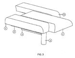
- FIG. 3 From Fig. 3 it is shown the seat of Figs. 1 and 2, but where the right seat part 1 is retracted somewhat in relation to the transversal frame 3 along the right gliding face 2. The rounded sides of the centre seat part are clearly shown. The left seat part 6 is shifted backwards, considerably further than the right seat part 1. From the figure it is shown how the right seat part 1, the centre seat part 5 and the left seat part 6 can be shifted in a plane, independently of each other.
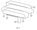
- FIG. 4 From Fig. 4 the seat from Figs. 1, 2 and 3 is shown, but where the right seat part 1 is extended forward in relation to the transversal frame 3 along the right gliding face 2. The left seat part 6 is shifted backwards. Also from Fig. 4 it is shown how the right seat part 1, the centre seat part 5 and the left seat part 6 can be shifted in a plane, independently of each other.
- Fig. 5 the underside of the seat is shown, where the right seat part 1, is attached to the transversal frame 3 by the right gliding face 2.
- the centre seat part 5 is secured to the transversal frame 3 with the centre gliding faces 9.
- the left seat part 6 is attached to the transversal frame 3 by the left gliding face 7.
- the gliding faces 2, 7 and 9 can be guiding rails, well known within the field, and can be of any suitable type.
- Locking handles 8 are shown placed behind the centre seat part 5. Locking handles 8 are provided to be able to lock the seat parts 1, 5, 6 in their desired positions. Right and left seat parts 1, 6 can be connected such that these can be led back and forth with only one handle.
- the locking mechanism that is controlled by the locking handles 8 may be of any kind, for instance based on lugs going into recesses in the respective elements, or be an infinitely variable friction mechanism.
- the locking handles 8 are preferably placed at the back of the chair seat, such that these can be operated by assisting personnel, such that a surgeon does not have to touch these. This is to maintain the hands of the surgeon sterile.
- Transversal seat frame 3 can be a simple plate with the gliding faces, guides or rails 2, 7, 9 fixed thereto.
- the seat frame 3 can be a suitable frame, fixture or some other suitable contraption for fixing the gliding faces 2,7,9.
- the shown chair 10 is both suitable as an office chair and as a chair that is suitable for a high sitting position or as a standing chair.
- the surgeon may prefer a tall sitting position for some operations and a lower position for other operations.
- the seat should have less support for the thighs, for example a saddle shape, whereas for low and more normal sitting positions it is common to need more support for the thighs.
- the shown seat can be adjusted and transformed such that the sitting face is optimised for all sitting positions.
- the adjustment of the sitting face can in alternative embodiments be performed electromechanically, electronically, pneumatically, hydraulically or in a combination of these.
- the chair seat is preferably intended used in connection with a chair with a chair back and an undercarriage, well known within the field.
- the chair is adapted for various sitting positions, and accordingly the chair undercarriage will normally be of a type with adjustable height.
- the chair seat is shown parted in three parts, but the seat may be made with several seat parts, for instance four or five.
- the embodiment shown on the figures with three parts is chosen because the balance of the chair easily can be accommodated for, and at the same time full flexibility is maintained.
Landscapes
- Health & Medical Sciences (AREA)
- Dentistry (AREA)
- General Health & Medical Sciences (AREA)
- Chair Legs, Seat Parts, And Backrests (AREA)
- Chairs For Special Purposes, Such As Reclining Chairs (AREA)
- Special Chairs (AREA)
- Chairs Characterized By Structure (AREA)
Description
- The present invention concerns a divided chair seat where the parts of the seat can be shifted independently of each other in a plane. The chair seat is particularly adapted for surgeons who in many cases must sit and work for several hours in a confined space with considerable precision. The chair seat is designed to be adaptable for many users with dissimilar anatomy and various forms of work.
- The chair seat can be adapted for many sitting positions, including partly standing positions, a backward position on the chair with a back supporting the stomach or chest, and an ordinary sitting position.
- An example of a chair for surgeons is shown in
US-A-5029941 showing a number of support functions and adjustment possibilities, but not a seat as defined in the present claim set. - An example of a three part seat is shown in NO-B-178483 describing a driver's chair for boats, where a boatman can have an ordinary sitting position, or a somewhat more standing position when the sides of the seat are hinged down and the seat is shaped as a saddle. The threeparted seat includes a fixed mid-section, and two side sections hinged in the mid-section, and that accordingly can be folded down.
- Yet another example of a three part seat is shown in NO-B-180221 showing a seat with hinged front parts making it possible for a user to change sitting position by changing the hip angle.
- Accordingly it has not been shown a chair seat with a parted sitting face where the separate parts can be shifted in relation to one another in a plane, substantially parallel to the sitting face of the seat as defined in the present claims. The chair seat includes three or more moving seat parts therebetween, shiftable or extendable in substantially one single plane. The seat may furthermore include a transversal frame, and the various parts of the chair seat may be fixed to the transversal frame via the gliding faces. The transversal frame can be adapted to be secured in a chair cylinder.
- The seat includes at least a right seat part, a centre seat part and a left seat part.
- The shiftable parts of the seat can be locked to the transversal frame with the locking mechanisms.
- The chair seat may be particularly adapted for a chair for surgeons. The chair seat may, however, also be well suited for others, for instance dentists, goldsmiths, boat drivers and other professions where greater flexibility in terms of sitting position may be advantageous.
- Short description of the enclosed drawings:
- Fig. 1 is a perspective view of an embodiment of a chair with a seat according to the invention;
- Fig. 2 is a perspective view of an embodiment of a seat according to the invention, where the parts of the seat are in a first position;
- Fig. 3 is perspective view of the embodiment of the seat shown on Fig. 2 where the parts of the seat are in a second position;
- Fig. 4 is a perspective view of the embodiment of the seat shown on Fig. 2 where the parts of the seat are in a third position; and
- Fig. 5 is a perspective view of the seat shown on Figs. 1 and 2 seen from below, and where the parts of the seat are in a fourth position.
- Detailed description of the present invention.
- From Fig. 1 it is shown a
chair 10 with aundercarriage 12, a chair back 13 and aseat 11 according to the invention. From the figure it is shown acentre seat part 5 with a saddle shape in an extended position such that thechair seat 11 is in a configuration that is adapted for a partly standing position. Furthermore, it is shown how theleft seat part 6 and theright seat part 1 are designed with a shape adapted to thecentre seat part 5 where the faces of the seat parts face each other. Achair cylinder 4 with a height adjustment is shown between thechair seat 11 and theundercarriage 12. - From Fig. 2 it is shown a chair seat according to the invention, where a
right seat part 1, acentre seat part 5 and aleft seat part 6 are mounted to atransversal frame 3. The transversal frame may be secured to achair cylinder 4. Thechair cylinder 4 may be connected to an ordinary chair undercarriage in a way otherwise well known within the field as shown on Fig. 1. - The seat parts can be adjusted in the longitudinal direction on the
transversal frame 3 throughgliding faces 2. Thecentre seat part 5 may have sides formed as a bow, such that when thecentre part 3 is led forward, and/or when theright seat part 1 and theleft seat part 6 are led backwards, thecentre seat part 5 will form the shape resembling a saddle shown on the other figures. Also in the this figure it is shown how theright seat part 1 and theleft seat part 6 are shaped with a shape adapted to the saddle shape of the mid-part, such that it is not created substantial recesses in the seat when the seat is placed in an initial position where the three seat parts are placed side by side without being shifted or extended in relation to each other. - From Fig. 3 it is shown the seat of Figs. 1 and 2, but where the
right seat part 1 is retracted somewhat in relation to thetransversal frame 3 along theright gliding face 2. The rounded sides of the centre seat part are clearly shown. Theleft seat part 6 is shifted backwards, considerably further than theright seat part 1. From the figure it is shown how theright seat part 1, thecentre seat part 5 and theleft seat part 6 can be shifted in a plane, independently of each other. - From Fig. 4 the seat from Figs. 1, 2 and 3 is shown, but where the
right seat part 1 is extended forward in relation to thetransversal frame 3 along theright gliding face 2. Theleft seat part 6 is shifted backwards. Also from Fig. 4 it is shown how theright seat part 1, thecentre seat part 5 and theleft seat part 6 can be shifted in a plane, independently of each other. - In Fig. 5 the underside of the seat is shown, where the
right seat part 1, is attached to thetransversal frame 3 by theright gliding face 2. Thecentre seat part 5 is secured to thetransversal frame 3 with thecentre gliding faces 9. Theleft seat part 6 is attached to thetransversal frame 3 by the leftgliding face 7. The gliding faces 2, 7 and 9 can be guiding rails, well known within the field, and can be of any suitable type.Locking handles 8 are shown placed behind thecentre seat part 5.Locking handles 8 are provided to be able to lock theseat parts left seat parts - The locking mechanism that is controlled by the
locking handles 8 may be of any kind, for instance based on lugs going into recesses in the respective elements, or be an infinitely variable friction mechanism. - The
locking handles 8 are preferably placed at the back of the chair seat, such that these can be operated by assisting personnel, such that a surgeon does not have to touch these. This is to maintain the hands of the surgeon sterile. -
Transversal seat frame 3 can be a simple plate with the gliding faces, guides orrails seat frame 3 can be a suitable frame, fixture or some other suitable contraption for fixing thegliding faces - The shown
chair 10 is both suitable as an office chair and as a chair that is suitable for a high sitting position or as a standing chair. In neurological operations the surgeon may prefer a tall sitting position for some operations and a lower position for other operations. To sit comfortably in partly standing tall positions the seat should have less support for the thighs, for example a saddle shape, whereas for low and more normal sitting positions it is common to need more support for the thighs. The shown seat can be adjusted and transformed such that the sitting face is optimised for all sitting positions. - The adjustment of the sitting face can in alternative embodiments be performed electromechanically, electronically, pneumatically, hydraulically or in a combination of these.
- The chair seat is preferably intended used in connection with a chair with a chair back and an undercarriage, well known within the field.
- The chair is adapted for various sitting positions, and accordingly the chair undercarriage will normally be of a type with adjustable height.
- The chair seat is shown parted in three parts, but the seat may be made with several seat parts, for instance four or five. The embodiment shown on the figures with three parts is chosen because the balance of the chair easily can be accommodated for, and at the same time full flexibility is maintained.
Claims (5)
- A chair seat (11) with at least a right (1), a centre (5) and a left (6) mutually moveable seat parts (1, 5, 6), the chair seat defining a first plane substantially parallel to a seat face of the seat,
characterised in that the parts (1, 5, 6) of the seat can be mutually shifted back and forth in relation to each other in a longitudinal direction of the chair seat (11) and substantially in the first plane, between an initial position where the seat parts are aligned with each other in the longitudinal direction and an extended position where the centre seat part (5) projects forwards in relation to the left and right seat parts (1, 6) in the longitudinal direction. - The chair seat (11) of claim 1
characterised in that the centre seat part (5) is substantially saddle or bow shaped and that the left and right seat parts (1, 6) include a shape adapted to the centre seat part (5) in that the faces of the left and right seat part (1, 6) towards the centre part (5) are adapted to the saddle shape of the centre part (5) such that substantial recesses not are created in the seat when the seat parts (1, 5, 6) are placed in the first position. - The chair seat (11) of claim 1,
characterised in that it further comprises a transversal frame (3), and that various parts of the chair seat (1, 5, 6) are secured to the transversal frame (3) by gliding faces (2, 7, 9) and that the transversal frame (3) is adapted to be secured to a chair cylinder (4). - The chair seat (11) of claim 3,
characterised in that the shiftable parts (1, 5, 6) of the seat (11) can be locked to the transversal frame (3) with the locking mechanisms (8). - Use of a chair seat (11) according to claim 1 in a chair for surgeons.
Applications Claiming Priority (2)
| Application Number | Priority Date | Filing Date | Title |
|---|---|---|---|
| NO20042020A NO320864B1 (en) | 2004-05-14 | 2004-05-14 | Chair seat with inviting movable seat parts |
| PCT/NO2005/000163 WO2005110156A1 (en) | 2004-05-14 | 2005-05-13 | Chair seat with mutually moveable parts |
Publications (2)
| Publication Number | Publication Date |
|---|---|
| EP1750549A1 EP1750549A1 (en) | 2007-02-14 |
| EP1750549B1 true EP1750549B1 (en) | 2007-11-21 |
Family
ID=34880520
Family Applications (1)
| Application Number | Title | Priority Date | Filing Date |
|---|---|---|---|
| EP05747451A Expired - Lifetime EP1750549B1 (en) | 2004-05-14 | 2005-05-13 | Chair seat with mutually moveable parts |
Country Status (7)
| Country | Link |
|---|---|
| US (1) | US7954896B2 (en) |
| EP (1) | EP1750549B1 (en) |
| JP (1) | JP4625073B2 (en) |
| CA (1) | CA2566669A1 (en) |
| DE (1) | DE602005003469T2 (en) |
| NO (1) | NO320864B1 (en) |
| WO (1) | WO2005110156A1 (en) |
Families Citing this family (4)
| Publication number | Priority date | Publication date | Assignee | Title |
|---|---|---|---|---|
| DE102010020503A1 (en) * | 2010-05-14 | 2011-11-17 | Josef Glöckl | Seat device with movable seat |
| US9493203B2 (en) * | 2014-03-04 | 2016-11-15 | Lyle Portz | Bicycle seat |
| WO2015186093A1 (en) | 2014-06-04 | 2015-12-10 | PASSON, Giancarlo | Seating element |
| KR101706126B1 (en) * | 2015-10-13 | 2017-02-14 | 선문대학교 산학협력단 | Seat for posture correction |
Family Cites Families (22)
| Publication number | Priority date | Publication date | Assignee | Title |
|---|---|---|---|---|
| US270273A (en) * | 1883-01-09 | Waeeen yount | ||
| US620946A (en) * | 1899-03-14 | Bicycle-saddle | ||
| US629956A (en) * | 1897-03-06 | 1899-08-01 | Warren H Craig | Bicycle-saddle. |
| US2087574A (en) * | 1936-06-10 | 1937-07-20 | Kaufer Moses | Sectional sofa or like furniture |
| US3568972A (en) * | 1969-04-14 | 1971-03-09 | Mc Donnell Douglas Corp | Integrated trackage pilot seat |
| JPS6074653A (en) | 1983-09-30 | 1985-04-26 | Nec Corp | Sealing jig for semiconductor device package |
| JPS6074653U (en) * | 1983-10-31 | 1985-05-25 | 白木金属工業株式会社 | Adjustable length cushion seat |
| JPS6160861A (en) | 1984-08-31 | 1986-03-28 | Toyota Motor Corp | Piston ring material made of steel |
| JPS6160861U (en) * | 1984-09-27 | 1986-04-24 | ||
| JPH01131348A (en) | 1987-11-16 | 1989-05-24 | Ishii Kogyo Kk | One-way rotary damper |
| JPH0517958Y2 (en) * | 1988-03-01 | 1993-05-13 | ||
| DE8903118U1 (en) * | 1989-02-16 | 1989-06-22 | J.D. Moeller Optische Werke Gmbh, 2000 Wedel | Surgeon’s chair |
| NO178483C (en) | 1992-07-17 | 1996-04-10 | Erling Koch | Wheelchair for boats |
| NO180221C (en) | 1994-10-10 | 1997-03-12 | Terje Dahlhaug | chair Seat |
| US5735573A (en) * | 1996-08-20 | 1998-04-07 | Vredevoogd; Jon D. | Chair with power seat |
| JPH10151033A (en) | 1996-09-30 | 1998-06-09 | Mikio Fukunaga | Chair |
| EP1091612A1 (en) * | 1999-10-04 | 2001-04-11 | Motorola, Inc. | Method to reduce handovers in mobile radio systems |
| NL1013253C2 (en) | 1999-10-08 | 2001-04-10 | Ergodynamics Holding B V | Combination of frame-supported seat and backrest. |
| US6554355B2 (en) * | 2000-12-05 | 2003-04-29 | Robert Kaptur | Anatomical bicycle seat |
| KR200260631Y1 (en) | 2001-10-24 | 2002-01-12 | 김선환 | Chair Having Separate Seat |
| KR100397267B1 (en) | 2003-06-12 | 2003-09-13 | 김선환 | Seat Apparatus Having Variable Gap |
| US6824220B1 (en) * | 2003-12-19 | 2004-11-30 | Gregory P. Davison | Modular furniture retaining system |
-
2004
- 2004-05-14 NO NO20042020A patent/NO320864B1/en not_active IP Right Cessation
-
2005
- 2005-05-13 WO PCT/NO2005/000163 patent/WO2005110156A1/en not_active Ceased
- 2005-05-13 CA CA002566669A patent/CA2566669A1/en not_active Abandoned
- 2005-05-13 DE DE602005003469T patent/DE602005003469T2/en not_active Expired - Lifetime
- 2005-05-13 US US11/596,522 patent/US7954896B2/en not_active Expired - Fee Related
- 2005-05-13 JP JP2007513089A patent/JP4625073B2/en not_active Expired - Fee Related
- 2005-05-13 EP EP05747451A patent/EP1750549B1/en not_active Expired - Lifetime
Also Published As
| Publication number | Publication date |
|---|---|
| NO20042020D0 (en) | 2004-05-14 |
| JP4625073B2 (en) | 2011-02-02 |
| US20090039686A1 (en) | 2009-02-12 |
| WO2005110156A1 (en) | 2005-11-24 |
| DE602005003469T2 (en) | 2008-09-25 |
| US7954896B2 (en) | 2011-06-07 |
| DE602005003469D1 (en) | 2008-01-03 |
| JP2007536983A (en) | 2007-12-20 |
| NO320864B1 (en) | 2006-02-06 |
| EP1750549A1 (en) | 2007-02-14 |
| CA2566669A1 (en) | 2005-11-24 |
| NO20042020L (en) | 2005-11-15 |
Similar Documents
| Publication | Publication Date | Title |
|---|---|---|
| US20080067850A1 (en) | Backrest for a chair | |
| US7784871B2 (en) | Occupational support system | |
| US9283871B2 (en) | Vehicle seat and utility motor vehicle comprising a vehicle seat | |
| EP0277145A1 (en) | ADJUSTABLE SEAT ARRANGEMENT. | |
| US20170252239A1 (en) | Adjustable Chair Assembly | |
| US9610864B2 (en) | Vehicle seat and utility motor vehicle comprising a vehicle seat | |
| EP2174630A1 (en) | Wheelchair comprising a foot support | |
| FR2791236A1 (en) | SUPPORT AND SUPPORT DEVICE FOR USE WITH A KEYBOARD ATTACHED TO THE EDGE OF THE WORKTOP | |
| US20150015045A1 (en) | Vehicle seat and utility motor vehicle comprising a vehicle seat | |
| WO2001071527A3 (en) | Ergonomic chair | |
| GB2129290A (en) | Patient support | |
| US20120112500A1 (en) | Vehicle Seating Apparatus | |
| US7954896B2 (en) | Chair seat with mutually moveable parts | |
| EP1717095A3 (en) | Reclining mechanism | |
| EP4112030B1 (en) | Extendable postural support cushion | |
| CN109278780A (en) | A business seat with adjustment function | |
| GB2390802A (en) | Furniture fitted with a motor driven body stretching device to extend the spine of the user | |
| US20070063563A1 (en) | Tiltable chair accommodating male and female user seating position preferences | |
| KR20100059407A (en) | Chair | |
| EP2540274B1 (en) | Mounting assembly | |
| JP2002119347A (en) | Chair | |
| JP5812912B2 (en) | Wheelchair table | |
| CN215993354U (en) | Seat backrest movement and locking device and seat | |
| ES2360170T3 (en) | PIECE OF FURNITURE. | |
| JP5108412B2 (en) | Length adjustment member for wheelchair seat |
Legal Events
| Date | Code | Title | Description |
|---|---|---|---|
| PUAI | Public reference made under article 153(3) epc to a published international application that has entered the european phase |
Free format text: ORIGINAL CODE: 0009012 |
|
| 17P | Request for examination filed |
Effective date: 20061206 |
|
| AK | Designated contracting states |
Kind code of ref document: A1 Designated state(s): AT BE BG CH CY CZ DE DK EE ES FI FR GB GR HU IE IS IT LI LT LU MC NL PL PT RO SE SI SK TR |
|
| GRAP | Despatch of communication of intention to grant a patent |
Free format text: ORIGINAL CODE: EPIDOSNIGR1 |
|
| DAX | Request for extension of the european patent (deleted) | ||
| GRAS | Grant fee paid |
Free format text: ORIGINAL CODE: EPIDOSNIGR3 |
|
| GRAA | (expected) grant |
Free format text: ORIGINAL CODE: 0009210 |
|
| AK | Designated contracting states |
Kind code of ref document: B1 Designated state(s): AT BE BG CH CY CZ DE DK EE ES FI FR GB GR HU IE IS IT LI LT LU MC NL PL PT RO SE SI SK TR |
|
| REG | Reference to a national code |
Ref country code: GB Ref legal event code: FG4D |
|
| REG | Reference to a national code |
Ref country code: IE Ref legal event code: FG4D |
|
| REG | Reference to a national code |
Ref country code: CH Ref legal event code: EP |
|
| REF | Corresponds to: |
Ref document number: 602005003469 Country of ref document: DE Date of ref document: 20080103 Kind code of ref document: P |
|
| RAP2 | Party data changed (patent owner data changed or rights of a patent transferred) |
Owner name: SINVENT AS |
|
| NLT2 | Nl: modifications (of names), taken from the european patent patent bulletin |
Owner name: SINVENT AS Effective date: 20080109 |
|
| PG25 | Lapsed in a contracting state [announced via postgrant information from national office to epo] |
Ref country code: ES Free format text: LAPSE BECAUSE OF FAILURE TO SUBMIT A TRANSLATION OF THE DESCRIPTION OR TO PAY THE FEE WITHIN THE PRESCRIBED TIME-LIMIT Effective date: 20080304 Ref country code: SE Free format text: LAPSE BECAUSE OF FAILURE TO SUBMIT A TRANSLATION OF THE DESCRIPTION OR TO PAY THE FEE WITHIN THE PRESCRIBED TIME-LIMIT Effective date: 20080221 Ref country code: NL Free format text: LAPSE BECAUSE OF FAILURE TO SUBMIT A TRANSLATION OF THE DESCRIPTION OR TO PAY THE FEE WITHIN THE PRESCRIBED TIME-LIMIT Effective date: 20071121 Ref country code: LI Free format text: LAPSE BECAUSE OF FAILURE TO SUBMIT A TRANSLATION OF THE DESCRIPTION OR TO PAY THE FEE WITHIN THE PRESCRIBED TIME-LIMIT Effective date: 20071121 Ref country code: CH Free format text: LAPSE BECAUSE OF FAILURE TO SUBMIT A TRANSLATION OF THE DESCRIPTION OR TO PAY THE FEE WITHIN THE PRESCRIBED TIME-LIMIT Effective date: 20071121 |
|
| NLV1 | Nl: lapsed or annulled due to failure to fulfill the requirements of art. 29p and 29m of the patents act | ||
| PG25 | Lapsed in a contracting state [announced via postgrant information from national office to epo] |
Ref country code: BG Free format text: LAPSE BECAUSE OF FAILURE TO SUBMIT A TRANSLATION OF THE DESCRIPTION OR TO PAY THE FEE WITHIN THE PRESCRIBED TIME-LIMIT Effective date: 20080221 Ref country code: IS Free format text: LAPSE BECAUSE OF FAILURE TO SUBMIT A TRANSLATION OF THE DESCRIPTION OR TO PAY THE FEE WITHIN THE PRESCRIBED TIME-LIMIT Effective date: 20080321 Ref country code: FI Free format text: LAPSE BECAUSE OF FAILURE TO SUBMIT A TRANSLATION OF THE DESCRIPTION OR TO PAY THE FEE WITHIN THE PRESCRIBED TIME-LIMIT Effective date: 20071121 Ref country code: LT Free format text: LAPSE BECAUSE OF FAILURE TO SUBMIT A TRANSLATION OF THE DESCRIPTION OR TO PAY THE FEE WITHIN THE PRESCRIBED TIME-LIMIT Effective date: 20071121 Ref country code: SI Free format text: LAPSE BECAUSE OF FAILURE TO SUBMIT A TRANSLATION OF THE DESCRIPTION OR TO PAY THE FEE WITHIN THE PRESCRIBED TIME-LIMIT Effective date: 20071121 Ref country code: PL Free format text: LAPSE BECAUSE OF FAILURE TO SUBMIT A TRANSLATION OF THE DESCRIPTION OR TO PAY THE FEE WITHIN THE PRESCRIBED TIME-LIMIT Effective date: 20071121 |
|
| REG | Reference to a national code |
Ref country code: CH Ref legal event code: PL |
|
| PG25 | Lapsed in a contracting state [announced via postgrant information from national office to epo] |
Ref country code: AT Free format text: LAPSE BECAUSE OF FAILURE TO SUBMIT A TRANSLATION OF THE DESCRIPTION OR TO PAY THE FEE WITHIN THE PRESCRIBED TIME-LIMIT Effective date: 20071121 |
|
| ET | Fr: translation filed | ||
| PG25 | Lapsed in a contracting state [announced via postgrant information from national office to epo] |
Ref country code: CZ Free format text: LAPSE BECAUSE OF FAILURE TO SUBMIT A TRANSLATION OF THE DESCRIPTION OR TO PAY THE FEE WITHIN THE PRESCRIBED TIME-LIMIT Effective date: 20071121 Ref country code: DK Free format text: LAPSE BECAUSE OF FAILURE TO SUBMIT A TRANSLATION OF THE DESCRIPTION OR TO PAY THE FEE WITHIN THE PRESCRIBED TIME-LIMIT Effective date: 20071121 |
|
| PG25 | Lapsed in a contracting state [announced via postgrant information from national office to epo] |
Ref country code: RO Free format text: LAPSE BECAUSE OF FAILURE TO SUBMIT A TRANSLATION OF THE DESCRIPTION OR TO PAY THE FEE WITHIN THE PRESCRIBED TIME-LIMIT Effective date: 20071121 Ref country code: BE Free format text: LAPSE BECAUSE OF FAILURE TO SUBMIT A TRANSLATION OF THE DESCRIPTION OR TO PAY THE FEE WITHIN THE PRESCRIBED TIME-LIMIT Effective date: 20071121 Ref country code: SK Free format text: LAPSE BECAUSE OF FAILURE TO SUBMIT A TRANSLATION OF THE DESCRIPTION OR TO PAY THE FEE WITHIN THE PRESCRIBED TIME-LIMIT Effective date: 20071121 |
|
| PLBE | No opposition filed within time limit |
Free format text: ORIGINAL CODE: 0009261 |
|
| STAA | Information on the status of an ep patent application or granted ep patent |
Free format text: STATUS: NO OPPOSITION FILED WITHIN TIME LIMIT |
|
| PG25 | Lapsed in a contracting state [announced via postgrant information from national office to epo] |
Ref country code: PT Free format text: LAPSE BECAUSE OF FAILURE TO SUBMIT A TRANSLATION OF THE DESCRIPTION OR TO PAY THE FEE WITHIN THE PRESCRIBED TIME-LIMIT Effective date: 20080421 |
|
| 26N | No opposition filed |
Effective date: 20080822 |
|
| PG25 | Lapsed in a contracting state [announced via postgrant information from national office to epo] |
Ref country code: MC Free format text: LAPSE BECAUSE OF NON-PAYMENT OF DUE FEES Effective date: 20080531 |
|
| PG25 | Lapsed in a contracting state [announced via postgrant information from national office to epo] |
Ref country code: EE Free format text: LAPSE BECAUSE OF FAILURE TO SUBMIT A TRANSLATION OF THE DESCRIPTION OR TO PAY THE FEE WITHIN THE PRESCRIBED TIME-LIMIT Effective date: 20071121 Ref country code: GR Free format text: LAPSE BECAUSE OF FAILURE TO SUBMIT A TRANSLATION OF THE DESCRIPTION OR TO PAY THE FEE WITHIN THE PRESCRIBED TIME-LIMIT Effective date: 20080222 |
|
| PG25 | Lapsed in a contracting state [announced via postgrant information from national office to epo] |
Ref country code: IE Free format text: LAPSE BECAUSE OF NON-PAYMENT OF DUE FEES Effective date: 20080513 |
|
| PG25 | Lapsed in a contracting state [announced via postgrant information from national office to epo] |
Ref country code: CY Free format text: LAPSE BECAUSE OF FAILURE TO SUBMIT A TRANSLATION OF THE DESCRIPTION OR TO PAY THE FEE WITHIN THE PRESCRIBED TIME-LIMIT Effective date: 20071121 |
|
| PG25 | Lapsed in a contracting state [announced via postgrant information from national office to epo] |
Ref country code: LU Free format text: LAPSE BECAUSE OF NON-PAYMENT OF DUE FEES Effective date: 20080513 Ref country code: HU Free format text: LAPSE BECAUSE OF FAILURE TO SUBMIT A TRANSLATION OF THE DESCRIPTION OR TO PAY THE FEE WITHIN THE PRESCRIBED TIME-LIMIT Effective date: 20080522 |
|
| PGFP | Annual fee paid to national office [announced via postgrant information from national office to epo] |
Ref country code: FR Payment date: 20100527 Year of fee payment: 6 |
|
| PG25 | Lapsed in a contracting state [announced via postgrant information from national office to epo] |
Ref country code: TR Free format text: LAPSE BECAUSE OF FAILURE TO SUBMIT A TRANSLATION OF THE DESCRIPTION OR TO PAY THE FEE WITHIN THE PRESCRIBED TIME-LIMIT Effective date: 20071121 |
|
| PGFP | Annual fee paid to national office [announced via postgrant information from national office to epo] |
Ref country code: IT Payment date: 20100512 Year of fee payment: 6 |
|
| REG | Reference to a national code |
Ref country code: FR Ref legal event code: ST Effective date: 20120131 |
|
| PG25 | Lapsed in a contracting state [announced via postgrant information from national office to epo] |
Ref country code: IT Free format text: LAPSE BECAUSE OF NON-PAYMENT OF DUE FEES Effective date: 20110513 |
|
| PG25 | Lapsed in a contracting state [announced via postgrant information from national office to epo] |
Ref country code: FR Free format text: LAPSE BECAUSE OF NON-PAYMENT OF DUE FEES Effective date: 20110531 |
|
| PGFP | Annual fee paid to national office [announced via postgrant information from national office to epo] |
Ref country code: GB Payment date: 20170519 Year of fee payment: 13 Ref country code: DE Payment date: 20170523 Year of fee payment: 13 |
|
| REG | Reference to a national code |
Ref country code: DE Ref legal event code: R119 Ref document number: 602005003469 Country of ref document: DE |
|
| GBPC | Gb: european patent ceased through non-payment of renewal fee |
Effective date: 20180513 |
|
| PG25 | Lapsed in a contracting state [announced via postgrant information from national office to epo] |
Ref country code: DE Free format text: LAPSE BECAUSE OF NON-PAYMENT OF DUE FEES Effective date: 20181201 Ref country code: GB Free format text: LAPSE BECAUSE OF NON-PAYMENT OF DUE FEES Effective date: 20180513 |