EP1750543B1 - Injection moulding process - Google Patents
Injection moulding process Download PDFInfo
- Publication number
- EP1750543B1 EP1750543B1 EP05715612A EP05715612A EP1750543B1 EP 1750543 B1 EP1750543 B1 EP 1750543B1 EP 05715612 A EP05715612 A EP 05715612A EP 05715612 A EP05715612 A EP 05715612A EP 1750543 B1 EP1750543 B1 EP 1750543B1
- Authority
- EP
- European Patent Office
- Prior art keywords
- mould
- elastomer material
- head
- mould cavity
- injection
- Prior art date
- Legal status (The legal status is an assumption and is not a legal conclusion. Google has not performed a legal analysis and makes no representation as to the accuracy of the status listed.)
- Expired - Lifetime
Links
Images



Classifications
-
- B—PERFORMING OPERATIONS; TRANSPORTING
- B29—WORKING OF PLASTICS; WORKING OF SUBSTANCES IN A PLASTIC STATE IN GENERAL
- B29C—SHAPING OR JOINING OF PLASTICS; SHAPING OF MATERIAL IN A PLASTIC STATE, NOT OTHERWISE PROVIDED FOR; AFTER-TREATMENT OF THE SHAPED PRODUCTS, e.g. REPAIRING
- B29C45/00—Injection moulding, i.e. forcing the required volume of moulding material through a nozzle into a closed mould; Apparatus therefor
- B29C45/14—Injection moulding, i.e. forcing the required volume of moulding material through a nozzle into a closed mould; Apparatus therefor incorporating preformed parts or layers, e.g. injection moulding around inserts or for coating articles
- B29C45/14336—Coating a portion of the article, e.g. the edge of the article
-
- B—PERFORMING OPERATIONS; TRANSPORTING
- B29—WORKING OF PLASTICS; WORKING OF SUBSTANCES IN A PLASTIC STATE IN GENERAL
- B29C—SHAPING OR JOINING OF PLASTICS; SHAPING OF MATERIAL IN A PLASTIC STATE, NOT OTHERWISE PROVIDED FOR; AFTER-TREATMENT OF THE SHAPED PRODUCTS, e.g. REPAIRING
- B29C45/00—Injection moulding, i.e. forcing the required volume of moulding material through a nozzle into a closed mould; Apparatus therefor
- B29C45/17—Component parts, details or accessories; Auxiliary operations
- B29C45/26—Moulds
- B29C45/34—Moulds having venting means
-
- B—PERFORMING OPERATIONS; TRANSPORTING
- B29—WORKING OF PLASTICS; WORKING OF SUBSTANCES IN A PLASTIC STATE IN GENERAL
- B29K—INDEXING SCHEME ASSOCIATED WITH SUBCLASSES B29B, B29C OR B29D, RELATING TO MOULDING MATERIALS OR TO MATERIALS FOR MOULDS, REINFORCEMENTS, FILLERS OR PREFORMED PARTS, e.g. INSERTS
- B29K2221/00—Use of unspecified rubbers as reinforcement
- B29K2221/003—Thermoplastic elastomers
-
- B—PERFORMING OPERATIONS; TRANSPORTING
- B29—WORKING OF PLASTICS; WORKING OF SUBSTANCES IN A PLASTIC STATE IN GENERAL
- B29L—INDEXING SCHEME ASSOCIATED WITH SUBCLASS B29C, RELATING TO PARTICULAR ARTICLES
- B29L2031/00—Other particular articles
- B29L2031/42—Brushes
- B29L2031/425—Toothbrush
-
- Y—GENERAL TAGGING OF NEW TECHNOLOGICAL DEVELOPMENTS; GENERAL TAGGING OF CROSS-SECTIONAL TECHNOLOGIES SPANNING OVER SEVERAL SECTIONS OF THE IPC; TECHNICAL SUBJECTS COVERED BY FORMER USPC CROSS-REFERENCE ART COLLECTIONS [XRACs] AND DIGESTS
- Y10—TECHNICAL SUBJECTS COVERED BY FORMER USPC
- Y10S—TECHNICAL SUBJECTS COVERED BY FORMER USPC CROSS-REFERENCE ART COLLECTIONS [XRACs] AND DIGESTS
- Y10S425/00—Plastic article or earthenware shaping or treating: apparatus
- Y10S425/812—Venting
Definitions
- This invention relates to an apparatus and to a process for making toothbrushes, in particular an injection moulding apparatus and process.
- Toothbrushes are well-known articles and normally comprise a head and a grip handle, generally with a narrowed neck region in between, all arranged along a longitudinal head-handle direction.
- Normally toothbrushes are made primarily of a plastic material, e.g. a polypropylene or styrol acryl nitrol ("SAN").
- SAN polypropylene or styrol acryl nitrol
- Many are so called two- component toothbrushes comprising a part made of plastic, e.g. the head and the main structure or “skeleton" of the handle, and a part made of a softer resilient elastomer, such as a thermoplastic elastomer e.g. Santoprene_ e.g. comprising part of the grip handle, to enhance grip, aesthetic appearance or to influence flexibility.
- Toothbrushes are disclosed for example in US-A-5,054,154 and EP-A-O 336 641 among others. Toothbrushes are also known incorporating one or more elastomer rib on the back of the brush head (opposite surface to that on which are mounted the bristles), e.g. WO-A-04/041025 and GB-A- 2 391 462 , for tongue cleaning.
- a toothbrush of this type is sold commercially by the present applicant under the name AQUAFRESH EXTREME CLEANTM.
- Toothbrushes are normally made by a process in which the plastic material part of their structure is first made, generally by injection moulding. Then this plastic part is enclosed in a mould cavity which defines the shape of the elastomer material part, and the elastomer material of the second component in a fluid state is injected into this mould cavity to form the elastomer material part. Normally the plastic material is formed with one or more cavity to receive this second material.
- US-A- 3,633,237 discloses such a toothbrush head having cavities in the plastic material part with which the elastomer part can engage.
- Such injection moulds are mould assemblies comprising one or more, generally two, mould blocks each with a part mould cavity therein, which when brought together in the assembled mould mate so that their part mould cavities combine to form a complete mould cavity between them, the surface across which they mate being Known in the art as the "split line”, and termed herein the "primary split line”.
- split line Known in the art as the "split line”, and termed herein the "primary split line”.
- WO-A-02/13656 for example describes such a process and suitable moulding machinery for its performance being a so called stack mould.
- toothbrush heads having an elastomer material part in the form of elastomer ribs extending transverse to the longitudinal direction, because during the injection of the elastomer material into the mould cavity air can become trapped in the parts of the mould cavity which define these ribs, for example as fluid elastomer material flows simultaneously from transversely opposite ends of these parts to trap air between these ends. This can result in voids in the so- formed elastomer part. It is an object of this invention to address this problem by providing a process and mould in which inter alia venting of air is improved, and flow of fluid elastomer material in the mould cavity is improved.
- this invention provides an apparatus for making a toothbrush head according to claim 1, and a process for making a toothbrush head using this apparatus according to claim 5.
- the plastic material head part may be provided by a conventional injection moulding process of the type used in the toothbrush art to manufacture plastic material parts of toothbrushes.
- air By providing such means to allow air to vent from the injection mould cavity during introduction of the thermoplastic elastomer material into the injection mould cavity other than via the primary split line air can escape from the cavity, and void formation can be reduced or eliminated.
- air is included any gaseous atmosphere in the mould cavity.
- vent is meant escape to the ambient environment.
- the rib may for example be in the form of a flexible lamella.
- a lamella may for example have a section, cut in the toothbrush longitudinal direction which tapers to be narrower remote from the second surface, e.g. of a wedge profile.
- a height dimension of ca. 1-3 mm is suitable.
- such a rib In their elongate direction, as seen in plan looking onto the second surface, such a rib may for example be straight, may for example be curved e.g. in an "S" shape or e.g. an arc with its convex side facing away from the handle, or for example be chevron shaped e.g. in a "V" shape with the "V" pointing away from the handle, or some other shape.
- thermoplastic elastomer material may be introduced into the second mould cavity by means of a conventional injection port of a type well known in the toothbrush making art, for example as generally disclosed in EP-A-0 749 281 .
- a conventional injection port of a type well known in the toothbrush making art, for example as generally disclosed in EP-A-0 749 281 .
- Such an injection port may pass through the second or first part mould block.
- a preferred thermoplastic elastomer material is the SEBS material TF3AAH from the supplier Kraiburg.
- first and second mould blocks mate at a primary split line which, when the head part is enclosed in the mould cavity, intersects the head part at the edge surface, between the first and second surfaces.
- the second mould block split line may preferably extend in the toothbrush longitudinal direction in a direction perpendicular to a plane between the first and second surfaces, preferably in a direction parallel to the toothbrush longitudinal direction.
- Such a second mould block split line may be sufficiently wide to allow the venting of air from the second part mould cavity but sufficiently narrow that no fluid elastomer material may escape.
- the two second part mould blocks are however fixed rigidly together against pressures and stresses of toothbrush manufacture, e.g. by bolts or an external frame.
- the first and second mould blocks mate at a primary split line which, when the head part is enclosed in the mould cavity, intersects the head part at the edge surface, between the first and second surfaces
- the second part mould cavity comprises one or more concavity deeming the shape of an elastomer part which comprises plural ribs having an elongate direction across the longitudinal direction, and extending from the second surface in a height direction perpendicular to a plane between the first and second surfaces
- the second mould block comprises at least two second part mould blocks which mate at a second mould block split line which extends in the toothbrush longitudinal direction.
- the injection mould cavity may completely enclose all the surface(s) of the head part upon which the elastomer part is to be formed, but need not completely enclose other parts of the toothbrush.
- the means to introduce thermoplastic elastomer material into the second mould cavity may comprise a conventional injection port of a type well known in the toothbrush making art, for example as generally disclosed in EP-A-0 749 281 .
- Such an injection port may pass through the second part mould block.
- the second surface of the head part, on which the elastomer material part is formed may incorporate structural features to enhance bonding of the elastomer material thereto.
- a structural feature may comprise a groove or discontinuous line of apertures in the second surface corresponding to the elongate direction of the rib.
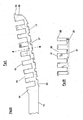
- a toothbrush 10 which comprises a head 11 and a grip handle 12, with a narrowed neck region 13 in between the head 11 and handle 12, all arranged along a longitudinal head- handle direction A- -A.
- the head 11 comprises a plastic material head part 14 which has a first surface 15 in which tufts 16 of bristles are mounted.
- the head part 14 has a second opposite surface 17 on which an elastomer material part 18 has been formed.
- the first and second surfaces 15, 17 are distanced by a side surface 19.
- Fig. 1A is a plan view looking down onto the first surface 15.
- Fig. 1C is a side view.
- the head part 14 has been formed integrally with handle 12 and neck 13 of polypropylene by injection moulding.
- the elastomer material part 18 is formed of the SEBS thermoplastic elastomer material Kraiburg TF3AAHTM.
- the elastomer part 18 comprises plural elastomer ribs 110.
- Fig. 1 shows that the ribs 110 are arranged sequentially longitudinally along the second surface 17 of head 11.
- Ribs 110 are in the form of flexible lamellae having an elongate direction transversely across the longitudinal direction A- -A, and extending from the second surface 17 in a height direction perpendicular to a plane between the first and second surfaces, with a height dimension "h" greater than their thickness dimension "t” (shown more clearly in Fig. 3 ) as measured in the toothbrush longitudinal direction.
- the lamellae have a section, cut in the toothbrush longitudinal direction A- -A which tapers as seen in Fig. 1C and 3 , to be narrower remote from the second surface 17, i.e. being of a wedge profile.
- ribs 110 are shown straight, but may be curved in an arc with its convex side facing away from the handle i.e. to the right as seen in Fig. 1 .
- Figs. 2 , 3 and 4 show the construction of head part 14 in more detail.
- Figs 2A and 3A show longitudinal sections and Figs 2B and 3B showing cross sections across the longitudinal axis A- - A about the lines B - - B of Figs. 2A and 3A .
- Fig 4 shows a plan view of the surface 17.
- Features shown in Fig. 1 are numbered correspondingly.
- Figs. 2 and 3 show conventional bristle holes 20 which have been formed in the plastic material of surface 15 of head part 14 using bristle pins in a conventional manner. Bristle tufts 16 are subsequently fixed into holes 20.
- grooves 21 In the opposite surface 17 are grooves 21 which facilitate the anchoring of the lamellae 110 into surface 17. Grooves 21 extend transversely to the longitudinal axis A- -A in positions corresponding to lamellae 110.
- flanges 22 Around the side surfaces 19 of head part 14 are flanges 22.
- a flow channel 23 also extends transversely across surface 17 and as seen in Fig. 4 around the edge of second surface 17.
- Fig. 5 shows a cross section through part 30 of an injection mould immediately adjacent to the mould cavity 31, and enclosing a head part 14 as shown in Fig. 1 sectioned as shown in Fig. 3B .
- Injection mould 30 may or may not also enclose handle 12.
- Fig. 6 shows a longitudinal section through the same part 30, enclosing the head part 14 as shown in Fig. 1 sectioned as shown in Fig. 3A , and shown enclosing part of handle 12.
- Fig. 6 shows a section cut along the line X - Y of Fig. 5 .
- Injection mould 30 comprises first 32 and second 33 mould blocks which include a respective first 34 and second 35 part mould cavity. Blocks 32 and 33 mate at a primary split line 36, so that the part mould cavities 34,35 combine to form the mould cavity 31.
- Primary split line 36 intersects the head part 14 enclosed in the cavity 31 at the edge surface 19 between the first 15 and second 17 surfaces.
- First part mould cavity 34 encloses the first surface 15, and the second part mould cavity 35 encloses the second surface 17 and includes a concavity 37 which defines the shape of the elastomer part 18 to be formed therein, concavity 37 being a shape complementary to the shape of the rib 110.
- the second mould block 33 incorporates a conventional injection moulding port 38 for introduction of a thermoplastic elastomer material into the second mould cavity 35 to thereby form the elastomer material part.
- the mating at line 36 is tight against escape of any elastomer material injected therein from cavity 35.
- Fig. 4 shows where the injection port 38 opens into the cavity 35 relative to the head part 14 enclosed therein, i.e. into a part adjacent to one of the grooves 21.
- Second mould block 33 comprises two second part mould blocks 33A, 33B which mate at a second mould block split line 39.
- Fig. 4 shows by dashed line S - - S the alignment of this split line 39, being the alignment of the toothbrush longitudinal direction A - - A. It is seen that this split line 39 extends in a direction perpendicular to a plane between the first and second surfaces 15, 17, i.e. the plane of primary split line 36.
- This second mould block split line 39 is sufficiently wide to allow the venting of air from the second part mould cavity 35 when fluid elastomer material is injected therein but is sufficiently narrow that no fluid elastomer material may escape.
- Split line 39 functions as a conduit communicating between the second part mould cavity and the outside of the mould block 33, in the form of a narrow slot extending in the toothbrush longitudinal direction A - A. As is seen from Fig. 4 this split line 39 provides communication between plural concavities 37 and the outside of the mould block 33.
- blocks 33A and 33B are firmly and rigidly fixed together mating at line 39, for example by means of bolts (not shown) or a surrounding frame (not shown) which clamps them together resistant to the stresses and pressures of use in the toothbrush manufacturing process.
- the mating of the blocks 33A and 33B at the line 39 is fluid- tight enough to prevent any escape of injected elastomer material via the line 39, the mating at line 39 allows air to vent from the interior of the cavity 35.
- the mould block 30 will be incorporated into conventional injection moulding machinery (not shown) of a type otherwise conventional in the toothbrush manufacturing art.
- the blocks 32,33A,33B are made of steel and the cavities 34,35 are formed therein using a conventional process of spark erosion (or electro- discharge machining) as commonly used in the art of making toothbrush moulds.
- the apparatus shown in Figs. 5 and 6 may be used to make a toothbrush head 11 as shown in Fig. 1 by the following process.
- a plastic material head part 14 as shown in Fig. 2 normally integrally made with its handle 12 and the neck part 13, is enclosed in the injection mould cavity 31, for example by first introducing the head part 14 into part mould cavity 34 in block 32, then mating block 32 with block 33 at primary split line 36 to form cavity 31 by combination of first and second part mould cavities 34, 35.
- the plastic material head part 14 may be introduced into the cavity 31 using manipulation procedures conventional in the toothbrush art.
- toothbrushes to be formed e.g. the handle 12 and neck 13 need not be enclosed in the cavity 31.
- the fluid elastomer material 18 is injected into cavity 31 via port 38.
- the fluid elastomer material 18 flows to all parts of cavity 31, including into concavity 35 to form the ribs 110, and to flow along conduit 23.
- flange 22 offsets the side surface 19 from the inside wall of the mould cavity 31, so that elastomer material flows between the head part 14 and the wall of the mould to deposit the elastomer material 18 as a layer around head part 14.
- the port 38 communicates with one of the concavities 17 in second mould cavity 33B, and the orifice between port 38 and concavity 37 can easily be made small enough that the residual disturbance of the shape of the rib 110 is inconspicuous.
- elastomer material 18 may follow the flow paths indicated by the arrows along the grooves 21 in surface 17 of head part 14. If elastomer material follows these flow paths then it will be appreciated that unless air in the cavity 31 is able to escape via split line 39 a bubble might be formed at or near the point 40, resulting in a void in the finished product.
- the venting of air from the second part mould cavity 35 during introduction of the thermoplastic elastomer material 18 into the second mould cavity 35 via second mould block split line 39 reduces the possibility of voids being formed in this way.
- the mould block 30 is then cooled to ca.35°, e.g. using conventional cooling lines (not shown) within block 30, until the elastomer material 18 is solid enough to allow the mould block 30 to be opened across the primary split line 36.
- the head part 14 with its so-formed elastomer material part 18 may then be ejected in a conventional manner, e.g. using ejector pins (not shown) from the mould cavity 34 or 35, and then tufts 16 of bristles may be inserted into bristle holes 20 in a conventional manner.
Landscapes
- Engineering & Computer Science (AREA)
- Manufacturing & Machinery (AREA)
- Mechanical Engineering (AREA)
- Brushes (AREA)
- Injection Moulding Of Plastics Or The Like (AREA)
- Moulds For Moulding Plastics Or The Like (AREA)
- Processing And Handling Of Plastics And Other Materials For Molding In General (AREA)
- Glass Compositions (AREA)
- Iron Core Of Rotating Electric Machines (AREA)
Abstract
Description
- This invention relates to an apparatus and to a process for making toothbrushes, in particular an injection moulding apparatus and process.
- Toothbrushes are well-known articles and normally comprise a head and a grip handle, generally with a narrowed neck region in between, all arranged along a longitudinal head-handle direction. Normally toothbrushes are made primarily of a plastic material, e.g. a polypropylene or styrol acryl nitrol ("SAN"). Many are so called two- component toothbrushes comprising a part made of plastic, e.g. the head and the main structure or "skeleton" of the handle, and a part made of a softer resilient elastomer, such as a thermoplastic elastomer e.g. Santoprene_ e.g. comprising part of the grip handle, to enhance grip, aesthetic appearance or to influence flexibility. Such toothbrushes are disclosed for example in
US-A-5,054,154 andEP-A-O 336 641 WO-A-04/041025 GB-A- 2 391 462 - Toothbrushes are normally made by a process in which the plastic material part of their structure is first made, generally by injection moulding. Then this plastic part is enclosed in a mould cavity which defines the shape of the elastomer material part, and the elastomer material of the second component in a fluid state is injected into this mould cavity to form the elastomer material part. Normally the plastic material is formed with one or more cavity to receive this second material.
US-A- 3,633,237 discloses such a toothbrush head having cavities in the plastic material part with which the elastomer part can engage. - Normally such injection moulds are mould assemblies comprising one or more, generally two, mould blocks each with a part mould cavity therein, which when brought together in the assembled mould mate so that their part mould cavities combine to form a complete mould cavity between them, the surface across which they mate being Known in the art as the "split line", and termed herein the "primary split line". Such processes are well known.
WO-A-02/13656 DE-A-199 43 599 ,JP-A-2003 033953 EP-A-1 312 455 ,DE-A-101 04 034 ,JP- A-2122910 JP-A-60046222 US-A-3,555,619 . - There is a problem in making toothbrush heads having an elastomer material part in the form of elastomer ribs extending transverse to the longitudinal direction, because during the injection of the elastomer material into the mould cavity air can become trapped in the parts of the mould cavity which define these ribs, for example as fluid elastomer material flows simultaneously from transversely opposite ends of these parts to trap air between these ends. This can result in voids in the so- formed elastomer part. It is an object of this invention to address this problem by providing a process and mould in which inter alia venting of air is improved, and flow of fluid elastomer material in the mould cavity is improved.
- Accordingly this invention provides an apparatus for making a toothbrush head according to claim 1, and a process for making a toothbrush head using this apparatus according to claim 5.
- The plastic material head part may be provided by a conventional injection moulding process of the type used in the toothbrush art to manufacture plastic material parts of toothbrushes.
- By providing such means to allow air to vent from the injection mould cavity during introduction of the thermoplastic elastomer material into the injection mould cavity other than via the primary split line air can escape from the cavity, and void formation can be reduced or eliminated. By "air" is included any gaseous atmosphere in the mould cavity. By "vent" is meant escape to the ambient environment.
- The rib may for example be in the form of a flexible lamella. Such a lamella may for example have a section, cut in the toothbrush longitudinal direction which tapers to be narrower remote from the second surface, e.g. of a wedge profile. Typically a height dimension of ca. 1-3 mm is suitable. In their elongate direction, as seen in plan looking onto the second surface, such a rib may for example be straight, may for example be curved e.g. in an "S" shape or e.g. an arc with its convex side facing away from the handle, or for example be chevron shaped e.g. in a "V" shape with the "V" pointing away from the handle, or some other shape.
- In the process of the invention the thermoplastic elastomer material may be introduced into the second mould cavity by means of a conventional injection port of a type well known in the toothbrush making art, for example as generally disclosed in
EP-A-0 749 281 . Such an injection port may pass through the second or first part mould block. A preferred thermoplastic elastomer material is the SEBS material TF3AAH from the supplier Kraiburg. - In an embodiment the first and second mould blocks mate at a primary split line which, when the head part is enclosed in the mould cavity, intersects the head part at the edge surface, between the first and second surfaces.
- The second mould block split line may preferably extend in the toothbrush longitudinal direction in a direction perpendicular to a plane between the first and second surfaces, preferably in a direction parallel to the toothbrush longitudinal direction. Such a second mould block split line may be sufficiently wide to allow the venting of air from the second part mould cavity but sufficiently narrow that no fluid elastomer material may escape. The two second part mould blocks are however fixed rigidly together against pressures and stresses of toothbrush manufacture, e.g. by bolts or an external frame.
- Therefore in a preferred apparatus of this invention: the first and second mould blocks mate at a primary split line which, when the head part is enclosed in the mould cavity, intersects the head part at the edge surface, between the first and second surfaces, the second part mould cavity comprises one or more concavity deeming the shape of an elastomer part which comprises plural ribs having an elongate direction across the longitudinal direction, and extending from the second surface in a height direction perpendicular to a plane between the first and second surfaces, the second mould block comprises at least two second part mould blocks which mate at a second mould block split line which extends in the toothbrush longitudinal direction.
- In the process and apparatus of this invention the injection mould cavity may completely enclose all the surface(s) of the head part upon which the elastomer part is to be formed, but need not completely enclose other parts of the toothbrush.
- In the process and apparatus of the invention the means to introduce thermoplastic elastomer material into the second mould cavity may comprise a conventional injection port of a type well known in the toothbrush making art, for example as generally disclosed in
EP-A-0 749 281 . Such an injection port may pass through the second part mould block. - For use in the process and apparatus of the invention the second surface of the head part, on which the elastomer material part is formed, may incorporate structural features to enhance bonding of the elastomer material thereto. For example in the case of the above-mentioned rib such a structural feature may comprise a groove or discontinuous line of apertures in the second surface corresponding to the elongate direction of the rib.
- The process and apparatus of this invention will now be described by way of example only with reference to
Figs. 1 to 6 which show: -
Fig. 1 A toothbrush made by the process of this invention. -
Fig. 2 Longitudinal and cross sections of the head part of the toothbrush shown inFig. 1 . -
Fig. 3 Longitudinal and cross sections of the head part of the toothbrush ofFig. 1 with the elastomer part in place. -
Fig. 4 Plan view of the second surface of the head part of the toothbrush shown inFig. 1 . -
Fig. 5 Cross section through an injection mould. -
Fig. 6 Longitudinal section through an injection mould. -
- 10
- toothbrush
- 11
- head
- 12
- grip handle
- 13
- neck region
- 14
- plastic material head part
- 15
- first surface
- 16
- tufts of bristles
- 17
- opposite surface
- 18
- elastomer material part
- 19
- side surface
- 110
- plural elastomer ribs
- 20
- bristle holes
- 21
- grooves
- 22
- flange
- 23
- flow channel
- 30
- part of an injection mould
- 31
- mould cavity
- 32
- first mould block
- 33
- second mould block
- 33A,33B
- second part mould blocks
- 34
- first part mould cavity
- 35
- second part mould cavity
- 36
- primary split line
- 37
- concavity
- 38
- injection moulding port
- 39
- second mould block split line
- 40
- bubble point
- Referring to
Fig. 1 , atoothbrush 10 is shown which comprises ahead 11 and agrip handle 12, with a narrowedneck region 13 in between thehead 11 and handle 12, all arranged along a longitudinal head- handle direction A- -A. Thehead 11 comprises a plasticmaterial head part 14 which has afirst surface 15 in whichtufts 16 of bristles are mounted. Thehead part 14 has a secondopposite surface 17 on which anelastomer material part 18 has been formed. The first andsecond surfaces side surface 19.Fig. 1A is a plan view looking down onto thefirst surface 15.Fig. 1C is a side view. - The
head part 14 has been formed integrally withhandle 12 andneck 13 of polypropylene by injection moulding. - The
elastomer material part 18 is formed of the SEBS thermoplastic elastomer material Kraiburg TF3AAH™. Theelastomer part 18 comprisesplural elastomer ribs 110.Fig. 1 shows that theribs 110 are arranged sequentially longitudinally along thesecond surface 17 ofhead 11.Ribs 110 are in the form of flexible lamellae having an elongate direction transversely across the longitudinal direction A- -A, and extending from thesecond surface 17 in a height direction perpendicular to a plane between the first and second surfaces, with a height dimension "h" greater than their thickness dimension "t" (shown more clearly inFig. 3 ) as measured in the toothbrush longitudinal direction. The lamellae have a section, cut in the toothbrush longitudinal direction A- -A which tapers as seen inFig. 1C and3 , to be narrower remote from thesecond surface 17, i.e. being of a wedge profile. In their elongate direction, as seen in plan inFig. 1B looking onto thesecond surface 17,ribs 110 are shown straight, but may be curved in an arc with its convex side facing away from the handle i.e. to the right as seen inFig. 1 . -
Figs. 2 ,3 and4 show the construction ofhead part 14 in more detail.Figs 2A and3A show longitudinal sections andFigs 2B and3B showing cross sections across the longitudinal axis A- - A about the lines B - - B ofFigs. 2A and3A .Fig 4 shows a plan view of thesurface 17. Features shown inFig. 1 are numbered correspondingly. -
Figs. 2 and3 show conventional bristle holes 20 which have been formed in the plastic material ofsurface 15 ofhead part 14 using bristle pins in a conventional manner.Bristle tufts 16 are subsequently fixed intoholes 20. In theopposite surface 17 aregrooves 21 which facilitate the anchoring of thelamellae 110 intosurface 17.Grooves 21 extend transversely to the longitudinal axis A- -A in positions corresponding tolamellae 110. Around the side surfaces 19 ofhead part 14 areflanges 22. Aflow channel 23 also extends transversely acrosssurface 17 and as seen inFig. 4 around the edge ofsecond surface 17. -
Fig. 5 shows a cross section throughpart 30 of an injection mould immediately adjacent to themould cavity 31, and enclosing ahead part 14 as shown inFig. 1 sectioned as shown inFig. 3B .Injection mould 30 may or may not also enclosehandle 12.Fig. 6 shows a longitudinal section through thesame part 30, enclosing thehead part 14 as shown inFig. 1 sectioned as shown inFig. 3A , and shown enclosing part ofhandle 12.Fig. 6 shows a section cut along the line X - Y ofFig. 5 . -
Injection mould 30 comprises first 32 and second 33 mould blocks which include a respective first 34 and second 35 part mould cavity.Blocks primary split line 36, so that thepart mould cavities mould cavity 31.Primary split line 36 intersects thehead part 14 enclosed in thecavity 31 at theedge surface 19 between the first 15 and second 17 surfaces. Firstpart mould cavity 34 encloses thefirst surface 15, and the secondpart mould cavity 35 encloses thesecond surface 17 and includes aconcavity 37 which defines the shape of theelastomer part 18 to be formed therein,concavity 37 being a shape complementary to the shape of therib 110. Thesecond mould block 33 incorporates a conventionalinjection moulding port 38 for introduction of a thermoplastic elastomer material into thesecond mould cavity 35 to thereby form the elastomer material part. The mating atline 36 is tight against escape of any elastomer material injected therein fromcavity 35.Fig. 4 shows where theinjection port 38 opens into thecavity 35 relative to thehead part 14 enclosed therein, i.e. into a part adjacent to one of thegrooves 21. -
Second mould block 33 comprises two second part mould blocks 33A, 33B which mate at a second mould block splitline 39.Fig. 4 shows by dashed line S - - S the alignment of thissplit line 39, being the alignment of the toothbrush longitudinal direction A - - A. It is seen that thissplit line 39 extends in a direction perpendicular to a plane between the first andsecond surfaces primary split line 36. This second mould block splitline 39 is sufficiently wide to allow the venting of air from the secondpart mould cavity 35 when fluid elastomer material is injected therein but is sufficiently narrow that no fluid elastomer material may escape.Split line 39 functions as a conduit communicating between the second part mould cavity and the outside of themould block 33, in the form of a narrow slot extending in the toothbrush longitudinal direction A - A. As is seen fromFig. 4 thissplit line 39 provides communication betweenplural concavities 37 and the outside of themould block 33. - Normally for
use blocks line 39, for example by means of bolts (not shown) or a surrounding frame (not shown) which clamps them together resistant to the stresses and pressures of use in the toothbrush manufacturing process. Although the mating of theblocks line 39 is fluid- tight enough to prevent any escape of injected elastomer material via theline 39, the mating atline 39 allows air to vent from the interior of thecavity 35. - Normally the
mould block 30 will be incorporated into conventional injection moulding machinery (not shown) of a type otherwise conventional in the toothbrush manufacturing art. Theblocks cavities - The apparatus shown in
Figs. 5 and6 may be used to make atoothbrush head 11 as shown inFig. 1 by the following process. - A plastic
material head part 14 as shown inFig. 2 , normally integrally made with itshandle 12 and theneck part 13, is enclosed in theinjection mould cavity 31, for example by first introducing thehead part 14 intopart mould cavity 34 inblock 32, thenmating block 32 withblock 33 atprimary split line 36 to formcavity 31 by combination of first and secondpart mould cavities material head part 14 may be introduced into thecavity 31 using manipulation procedures conventional in the toothbrush art. - Other parts of the toothbrush to be formed, e.g. the
handle 12 andneck 13 need not be enclosed in thecavity 31. - When the
blocks elastomer material 18, thefluid elastomer material 18 is injected intocavity 31 viaport 38. Typically Kraiburg SEBS TF3AAH may be injected in at a temperature of 250°. Thefluid elastomer material 18 flows to all parts ofcavity 31, including intoconcavity 35 to form theribs 110, and to flow alongconduit 23. It is seen thatflange 22 offsets theside surface 19 from the inside wall of themould cavity 31, so that elastomer material flows between thehead part 14 and the wall of the mould to deposit theelastomer material 18 as a layer aroundhead part 14. Theport 38 communicates with one of theconcavities 17 insecond mould cavity 33B, and the orifice betweenport 38 andconcavity 37 can easily be made small enough that the residual disturbance of the shape of therib 110 is inconspicuous. - From
Fig. 4 it is seen thatelastomer material 18 may follow the flow paths indicated by the arrows along thegrooves 21 insurface 17 ofhead part 14. If elastomer material follows these flow paths then it will be appreciated that unless air in thecavity 31 is able to escape via split line 39 a bubble might be formed at or near thepoint 40, resulting in a void in the finished product. The venting of air from the secondpart mould cavity 35 during introduction of thethermoplastic elastomer material 18 into thesecond mould cavity 35 via second mould block splitline 39 reduces the possibility of voids being formed in this way. - The
mould block 30 is then cooled to ca.35°, e.g. using conventional cooling lines (not shown) withinblock 30, until theelastomer material 18 is solid enough to allow themould block 30 to be opened across theprimary split line 36. Thehead part 14 with its so-formedelastomer material part 18 may then be ejected in a conventional manner, e.g. using ejector pins (not shown) from themould cavity tufts 16 of bristles may be inserted into bristle holes 20 in a conventional manner.
Claims (5)
- Apparatus for making a toothbrush head (11) for a toothbrush of the type comprising a head (11) and a grip handle and having a longitudinal head-handle direction, by means of a process which comprises providing a plastic material head part (14) having a first surface (15) in which bristles (16) are mounted or are to be mounted, and having a second opposite surface (17) on which an elastomer material part (18) is to be formed, the first and opposite surfaces (15,17) being distanced by a side surface (19), enclosing the head part (14) in an injection mould cavity (31) defining at least part of the shape of the elastomer part (18) to be formed, introducing a thermoplastic elastomer material into the injection mould cavity (31) to thereby form the elastomer material part (18), the apparatus comprising an injection mould (30) which comprises first and second mould blocks (32,33) which include a respective first and second part mould cavity (34,35) and which mate at a primary split line (36), so that the part mould cavities (34,35) combine to form a mould cavity (31) suitable to enclose the plastic material head part (14), and the second part mould cavity (35) comprises one or more concavity defining the shape of an elastomer part (18) which comprises plural ribs (110) having an elongate direction across the longitudinal direction, and extending from the second surface (17) in a height direction perpendicular to a plane between the first and second surfaces (15,17), the injection mould (30) being adapted for introduction of a thermoplastic elastomer material into the second part mould cavity (35) to thereby form the elastomer material part (18):characterised in that: the second mould block (33) comprises at least two part second mould blocks (33) which mate at a second mould block split line (39) which extends in the toothbrush longitudinal direction, said second mould block split line (39) comprising means which allow air to vent from the injection mould cavity (31) during introduction of the thermoplastic elastomer material into the injection mould cavity (31) other than via the primary split line (36).
- Apparatus according to claim 1 characterised in that the concavity defines the shape of a rib (110) which has a section cut in the longitudinal toothbrush directon which tapers to be narrower remote from the second surface (17).
- Apparatus according to claim 1 characterised by an injection port (38) for thermoplastic elastomer material passing through the second mould block (33).
- Apparatus according to claim 1, 2 or 3 characterised in that the second mould block split line is sufficiently wide to allow the venting of air from the second mould block cavity, but sufficiently narrow that no fluid elastomer material escapes during injection of thermoplastic elastomer material into the injection mould cavity (31).
- A process in which 1 a toothbrush head (11) for a toothbrush of the type comprising a head (11) and a grip handle (12) and having a longitudinal head-handle direction, and comprising a plastic material head part (14) having a first surface (15) in which bristles (16) are mounted or are to be mounted, and having a second opposite surface (17) on which an elastomer material part (18) is formed, the first and opposite surfaces (15,17) being distanced by a side surface is made, the process characterised by:enclosing the head part (14) in an injection mould cavity (31) of an apparatus as claimed in any one of claims 1 to 4, introducing a thermoplastic elastomer material into the injection mould cavity (31) to thereby form the elastomer material part (18), and allowing air to vent from the injection mould cavity (31) during introduction of the thermoplastic elastomer material into the injection mould cavity (31) via the second mould block split line (39).
Applications Claiming Priority (2)
| Application Number | Priority Date | Filing Date | Title |
|---|---|---|---|
| GBGB0404583.7A GB0404583D0 (en) | 2004-03-01 | 2004-03-01 | Process |
| PCT/EP2005/002111 WO2005084487A2 (en) | 2004-03-01 | 2005-02-25 | Injection moulding process |
Publications (2)
| Publication Number | Publication Date |
|---|---|
| EP1750543A2 EP1750543A2 (en) | 2007-02-14 |
| EP1750543B1 true EP1750543B1 (en) | 2010-11-17 |
Family
ID=32088503
Family Applications (1)
| Application Number | Title | Priority Date | Filing Date |
|---|---|---|---|
| EP05715612A Expired - Lifetime EP1750543B1 (en) | 2004-03-01 | 2005-02-25 | Injection moulding process |
Country Status (8)
| Country | Link |
|---|---|
| US (1) | US7691309B2 (en) |
| EP (1) | EP1750543B1 (en) |
| JP (1) | JP4764413B2 (en) |
| AT (1) | ATE488155T1 (en) |
| DE (1) | DE602005024796D1 (en) |
| ES (1) | ES2352449T3 (en) |
| GB (1) | GB0404583D0 (en) |
| WO (1) | WO2005084487A2 (en) |
Families Citing this family (7)
| Publication number | Priority date | Publication date | Assignee | Title |
|---|---|---|---|---|
| US8510893B2 (en) | 2008-06-20 | 2013-08-20 | Colgate-Palmolive Company | Toothbrush with visual and/or other sensory effects |
| DE102011011323A1 (en) * | 2011-02-16 | 2012-08-16 | Interbros Gmbh | Mouth or tooth cleaning device |
| WO2014070542A1 (en) * | 2012-11-05 | 2014-05-08 | The Gillette Company | Toothbrush comprising elastomeric cleaning elements over-molded with a harder plastic and method for producing the same |
| US9802347B2 (en) | 2015-02-02 | 2017-10-31 | Colgate-Palmolive Company | Method of forming an oral care implement |
| USD777446S1 (en) | 2015-07-23 | 2017-01-31 | Colgate-Palmolive Company | Oral care implement handle |
| CN107920654A (en) | 2015-07-23 | 2018-04-17 | 高露洁-棕榄公司 | Oral care implement |
| CN105711034B (en) * | 2016-03-18 | 2018-10-16 | 广东小天才科技有限公司 | Injection molding process |
Family Cites Families (20)
| Publication number | Priority date | Publication date | Assignee | Title |
|---|---|---|---|---|
| JPS6046222A (en) * | 1983-08-24 | 1985-03-13 | Matsushita Electric Ind Co Ltd | Mold device for vacuum exhaustion |
| US4909972A (en) * | 1985-12-02 | 1990-03-20 | Britz Johannes H | Method and apparatus for making a solid foamed tire core |
| GB9106511D0 (en) * | 1991-03-27 | 1991-05-15 | Lingner & Fischer Gmbh | Novel article |
| FR2690318A1 (en) * | 1992-04-27 | 1993-10-29 | Oreal | Brush intended for the application of a cosmetic product, in particular on the eyelashes or the hair, and method of manufacturing such a brush. |
| DE4229152A1 (en) * | 1992-09-01 | 1994-03-03 | Jordan As Oslo | Toothbrush and manufacturing process for toothbrushes |
| US6408476B1 (en) * | 1996-01-18 | 2002-06-25 | The Procter & Gamble Company | Toothbrush with elastomer filled flexible head |
| FR2756509B1 (en) * | 1996-12-04 | 1999-01-08 | Oreal | BLOW MOLDING OF A THERMOPLASTIC CONTAINER |
| US6514445B1 (en) * | 1996-12-24 | 2003-02-04 | The Procter & Gamble Company | Brush making |
| TW467734B (en) | 1998-09-10 | 2001-12-11 | Colgate Palmolive Co | Toothbrush head with an elastomeric bumper and method of production thereof |
| AUPP784098A0 (en) * | 1998-12-18 | 1999-01-21 | Filter Technology Australia Pty Limited | A filter cartridge and process |
| US6306238B1 (en) * | 1999-06-10 | 2001-10-23 | General Mills, Inc. | Thermal annealing of plastic pieces |
| JP2001070043A (en) * | 1999-09-02 | 2001-03-21 | Koeisha:Kk | Gum massage brush |
| DE19943599A1 (en) * | 1999-09-11 | 2001-03-15 | Zahoransky Anton Gmbh & Co | Brush manufacturing machine has mould halves, one of which, contains cassette with channels into which ends of bundles of bristles are inserted for bonding together by injection molding and which is fitted with sealing plate |
| DE10005738A1 (en) * | 2000-02-09 | 2001-08-23 | Trisa Holding Ag Triengen | Hollow toothbrush handle is composed of two shell sections bonded together in an injection mold by an injected seam along the joint between them |
| DE10104034A1 (en) * | 2001-01-31 | 2002-08-01 | Zahoransky Anton Gmbh & Co | Machine for making brush bodies or brushes by injection molding has vent channel next to mold cavity and separated from it by thin strip, channel connecting with vent leading to atmosphere |
| JP2003033953A (en) * | 2001-07-26 | 2003-02-04 | Sony Corp | Injection mold apparatus and injection molding method |
| JP3976647B2 (en) * | 2001-08-24 | 2007-09-19 | 花王株式会社 | Toothbrush manufacturing method and toothbrush |
| JP2003144232A (en) * | 2001-08-30 | 2003-05-20 | Lion Corp | Manufacturing method of toothbrush handle |
| JP3981808B2 (en) * | 2001-11-19 | 2007-09-26 | 信越化学工業株式会社 | Injection mold and method for producing injection molded product using the same |
| AU2003283323A1 (en) * | 2002-11-06 | 2004-06-07 | Unilever Plc | Toothbrush |
-
2004
- 2004-03-01 GB GBGB0404583.7A patent/GB0404583D0/en not_active Ceased
-
2005
- 2005-02-25 US US10/591,062 patent/US7691309B2/en not_active Expired - Lifetime
- 2005-02-25 WO PCT/EP2005/002111 patent/WO2005084487A2/en not_active Ceased
- 2005-02-25 ES ES05715612T patent/ES2352449T3/en not_active Expired - Lifetime
- 2005-02-25 DE DE602005024796T patent/DE602005024796D1/en not_active Expired - Lifetime
- 2005-02-25 AT AT05715612T patent/ATE488155T1/en not_active IP Right Cessation
- 2005-02-25 JP JP2007501192A patent/JP4764413B2/en not_active Expired - Lifetime
- 2005-02-25 EP EP05715612A patent/EP1750543B1/en not_active Expired - Lifetime
Also Published As
| Publication number | Publication date |
|---|---|
| US20080164633A1 (en) | 2008-07-10 |
| JP2007525294A (en) | 2007-09-06 |
| EP1750543A2 (en) | 2007-02-14 |
| ATE488155T1 (en) | 2010-12-15 |
| JP4764413B2 (en) | 2011-09-07 |
| ES2352449T3 (en) | 2011-02-18 |
| DE602005024796D1 (en) | 2010-12-30 |
| US7691309B2 (en) | 2010-04-06 |
| GB0404583D0 (en) | 2004-04-07 |
| WO2005084487A3 (en) | 2005-10-27 |
| WO2005084487A2 (en) | 2005-09-15 |
Similar Documents
| Publication | Publication Date | Title |
|---|---|---|
| US7297303B2 (en) | Process of injection molding composite articles and toothbrush obtainable thereby | |
| US4422986A (en) | Method and apparatus for infection molding brushes | |
| US6402494B1 (en) | Apparatus for producing a toothbrush | |
| KR20020079735A (en) | Toothbrush | |
| US20050045361A1 (en) | Harness protector and method for producing the same | |
| US7691309B2 (en) | Process for making a toothbrush | |
| KR20110056381A (en) | How to make a brush, especially a toothbrush | |
| MXPA02008312A (en) | Method for producing a toothbrush. | |
| CA2503778A1 (en) | Toothbrush and process for producing the same | |
| JPH05295642A (en) | Ball chain in continuous length and connecting tool | |
| EP1684964B1 (en) | Process for making toothbrushes | |
| EP1311176B1 (en) | Process for making a toothbrush | |
| GB2071558A (en) | Moulding Brushes | |
| JPH06155509A (en) | Method for manufacturing resin tubular body | |
| JP2024095268A (en) | Toothbrush handle, toothbrush, and method for manufacturing toothbrush handle | |
| JPH06155501A (en) | Production of resin tubular body | |
| JP2003112364A (en) | Split mold and container manufacturing method using the split mold | |
| KR102907557B1 (en) | Double injection molding die for preventing depression on textured surface of injection molded part | |
| JP4080502B2 (en) | Hollow double wall molded product | |
| JPS6130895B2 (en) | ||
| JP2005144748A (en) | Multicolor molded product and molding method thereof | |
| WO1994022652A1 (en) | Apparatus for and a method of injection moulding | |
| JPH0857887A (en) | Manufacture of hollow resin molded form | |
| JP2004181662A (en) | Foam molding insert and method for producing foam molding | |
| HK1010822A1 (en) | Toothbrush |
Legal Events
| Date | Code | Title | Description |
|---|---|---|---|
| PUAI | Public reference made under article 153(3) epc to a published international application that has entered the european phase |
Free format text: ORIGINAL CODE: 0009012 |
|
| 17P | Request for examination filed |
Effective date: 20060928 |
|
| AK | Designated contracting states |
Kind code of ref document: A2 Designated state(s): AT BE BG CH CY CZ DE DK EE ES FI FR GB GR HU IE IS IT LI LT LU MC NL PL PT RO SE SI SK TR |
|
| AX | Request for extension of the european patent |
Extension state: HR LV |
|
| 17Q | First examination report despatched |
Effective date: 20070508 |
|
| RAX | Requested extension states of the european patent have changed |
Extension state: HR Payment date: 20060928 Extension state: LV Payment date: 20060928 |
|
| GRAP | Despatch of communication of intention to grant a patent |
Free format text: ORIGINAL CODE: EPIDOSNIGR1 |
|
| RIN1 | Information on inventor provided before grant (corrected) |
Inventor name: EBNER, WINFRIED Inventor name: MUELLER, WOLF-DIETER |
|
| GRAS | Grant fee paid |
Free format text: ORIGINAL CODE: EPIDOSNIGR3 |
|
| GRAA | (expected) grant |
Free format text: ORIGINAL CODE: 0009210 |
|
| AK | Designated contracting states |
Kind code of ref document: B1 Designated state(s): AT BE BG CH CY CZ DE DK EE ES FI FR GB GR HU IE IS IT LI LT LU MC NL PL PT RO SE SI SK TR |
|
| AX | Request for extension of the european patent |
Extension state: HR LV |
|
| REG | Reference to a national code |
Ref country code: GB Ref legal event code: FG4D |
|
| REG | Reference to a national code |
Ref country code: CH Ref legal event code: EP Ref country code: CH Ref legal event code: NV Representative=s name: ISLER & PEDRAZZINI AG |
|
| REG | Reference to a national code |
Ref country code: IE Ref legal event code: FG4D Ref country code: NL Ref legal event code: T3 |
|
| REF | Corresponds to: |
Ref document number: 602005024796 Country of ref document: DE Date of ref document: 20101230 Kind code of ref document: P |
|
| REG | Reference to a national code |
Ref country code: SE Ref legal event code: TRGR |
|
| REG | Reference to a national code |
Ref country code: ES Ref legal event code: FG2A Effective date: 20110208 |
|
| LTIE | Lt: invalidation of european patent or patent extension |
Effective date: 20101117 |
|
| PG25 | Lapsed in a contracting state [announced via postgrant information from national office to epo] |
Ref country code: LT Free format text: LAPSE BECAUSE OF FAILURE TO SUBMIT A TRANSLATION OF THE DESCRIPTION OR TO PAY THE FEE WITHIN THE PRESCRIBED TIME-LIMIT Effective date: 20101117 |
|
| PG25 | Lapsed in a contracting state [announced via postgrant information from national office to epo] |
Ref country code: SI Free format text: LAPSE BECAUSE OF FAILURE TO SUBMIT A TRANSLATION OF THE DESCRIPTION OR TO PAY THE FEE WITHIN THE PRESCRIBED TIME-LIMIT Effective date: 20101117 Ref country code: AT Free format text: LAPSE BECAUSE OF FAILURE TO SUBMIT A TRANSLATION OF THE DESCRIPTION OR TO PAY THE FEE WITHIN THE PRESCRIBED TIME-LIMIT Effective date: 20101117 Ref country code: IS Free format text: LAPSE BECAUSE OF FAILURE TO SUBMIT A TRANSLATION OF THE DESCRIPTION OR TO PAY THE FEE WITHIN THE PRESCRIBED TIME-LIMIT Effective date: 20110317 Ref country code: CY Free format text: LAPSE BECAUSE OF FAILURE TO SUBMIT A TRANSLATION OF THE DESCRIPTION OR TO PAY THE FEE WITHIN THE PRESCRIBED TIME-LIMIT Effective date: 20101117 Ref country code: FI Free format text: LAPSE BECAUSE OF FAILURE TO SUBMIT A TRANSLATION OF THE DESCRIPTION OR TO PAY THE FEE WITHIN THE PRESCRIBED TIME-LIMIT Effective date: 20101117 Ref country code: PT Free format text: LAPSE BECAUSE OF FAILURE TO SUBMIT A TRANSLATION OF THE DESCRIPTION OR TO PAY THE FEE WITHIN THE PRESCRIBED TIME-LIMIT Effective date: 20110317 Ref country code: BG Free format text: LAPSE BECAUSE OF FAILURE TO SUBMIT A TRANSLATION OF THE DESCRIPTION OR TO PAY THE FEE WITHIN THE PRESCRIBED TIME-LIMIT Effective date: 20110217 |
|
| PG25 | Lapsed in a contracting state [announced via postgrant information from national office to epo] |
Ref country code: GR Free format text: LAPSE BECAUSE OF FAILURE TO SUBMIT A TRANSLATION OF THE DESCRIPTION OR TO PAY THE FEE WITHIN THE PRESCRIBED TIME-LIMIT Effective date: 20110218 |
|
| PG25 | Lapsed in a contracting state [announced via postgrant information from national office to epo] |
Ref country code: CZ Free format text: LAPSE BECAUSE OF FAILURE TO SUBMIT A TRANSLATION OF THE DESCRIPTION OR TO PAY THE FEE WITHIN THE PRESCRIBED TIME-LIMIT Effective date: 20101117 Ref country code: EE Free format text: LAPSE BECAUSE OF FAILURE TO SUBMIT A TRANSLATION OF THE DESCRIPTION OR TO PAY THE FEE WITHIN THE PRESCRIBED TIME-LIMIT Effective date: 20101117 |
|
| PG25 | Lapsed in a contracting state [announced via postgrant information from national office to epo] |
Ref country code: PL Free format text: LAPSE BECAUSE OF FAILURE TO SUBMIT A TRANSLATION OF THE DESCRIPTION OR TO PAY THE FEE WITHIN THE PRESCRIBED TIME-LIMIT Effective date: 20101117 Ref country code: DK Free format text: LAPSE BECAUSE OF FAILURE TO SUBMIT A TRANSLATION OF THE DESCRIPTION OR TO PAY THE FEE WITHIN THE PRESCRIBED TIME-LIMIT Effective date: 20101117 Ref country code: SK Free format text: LAPSE BECAUSE OF FAILURE TO SUBMIT A TRANSLATION OF THE DESCRIPTION OR TO PAY THE FEE WITHIN THE PRESCRIBED TIME-LIMIT Effective date: 20101117 Ref country code: RO Free format text: LAPSE BECAUSE OF FAILURE TO SUBMIT A TRANSLATION OF THE DESCRIPTION OR TO PAY THE FEE WITHIN THE PRESCRIBED TIME-LIMIT Effective date: 20101117 |
|
| PLBE | No opposition filed within time limit |
Free format text: ORIGINAL CODE: 0009261 |
|
| STAA | Information on the status of an ep patent application or granted ep patent |
Free format text: STATUS: NO OPPOSITION FILED WITHIN TIME LIMIT |
|
| PG25 | Lapsed in a contracting state [announced via postgrant information from national office to epo] |
Ref country code: MC Free format text: LAPSE BECAUSE OF NON-PAYMENT OF DUE FEES Effective date: 20110228 |
|
| 26N | No opposition filed |
Effective date: 20110818 |
|
| REG | Reference to a national code |
Ref country code: IE Ref legal event code: MM4A |
|
| REG | Reference to a national code |
Ref country code: DE Ref legal event code: R097 Ref document number: 602005024796 Country of ref document: DE Effective date: 20110818 |
|
| PG25 | Lapsed in a contracting state [announced via postgrant information from national office to epo] |
Ref country code: IE Free format text: LAPSE BECAUSE OF NON-PAYMENT OF DUE FEES Effective date: 20110225 |
|
| PG25 | Lapsed in a contracting state [announced via postgrant information from national office to epo] |
Ref country code: LU Free format text: LAPSE BECAUSE OF NON-PAYMENT OF DUE FEES Effective date: 20110225 |
|
| PG25 | Lapsed in a contracting state [announced via postgrant information from national office to epo] |
Ref country code: TR Free format text: LAPSE BECAUSE OF FAILURE TO SUBMIT A TRANSLATION OF THE DESCRIPTION OR TO PAY THE FEE WITHIN THE PRESCRIBED TIME-LIMIT Effective date: 20101117 |
|
| PG25 | Lapsed in a contracting state [announced via postgrant information from national office to epo] |
Ref country code: HU Free format text: LAPSE BECAUSE OF FAILURE TO SUBMIT A TRANSLATION OF THE DESCRIPTION OR TO PAY THE FEE WITHIN THE PRESCRIBED TIME-LIMIT Effective date: 20101117 |
|
| REG | Reference to a national code |
Ref country code: FR Ref legal event code: PLFP Year of fee payment: 12 |
|
| PGFP | Annual fee paid to national office [announced via postgrant information from national office to epo] |
Ref country code: ES Payment date: 20160217 Year of fee payment: 12 Ref country code: CH Payment date: 20160125 Year of fee payment: 12 |
|
| PGFP | Annual fee paid to national office [announced via postgrant information from national office to epo] |
Ref country code: SE Payment date: 20160208 Year of fee payment: 12 Ref country code: NL Payment date: 20160205 Year of fee payment: 12 Ref country code: BE Payment date: 20160218 Year of fee payment: 12 |
|
| REG | Reference to a national code |
Ref country code: FR Ref legal event code: PLFP Year of fee payment: 13 |
|
| PG25 | Lapsed in a contracting state [announced via postgrant information from national office to epo] |
Ref country code: BE Free format text: LAPSE BECAUSE OF NON-PAYMENT OF DUE FEES Effective date: 20170228 |
|
| REG | Reference to a national code |
Ref country code: CH Ref legal event code: PL |
|
| REG | Reference to a national code |
Ref country code: SE Ref legal event code: EUG |
|
| REG | Reference to a national code |
Ref country code: NL Ref legal event code: MM Effective date: 20170301 |
|
| PG25 | Lapsed in a contracting state [announced via postgrant information from national office to epo] |
Ref country code: LI Free format text: LAPSE BECAUSE OF NON-PAYMENT OF DUE FEES Effective date: 20170228 Ref country code: CH Free format text: LAPSE BECAUSE OF NON-PAYMENT OF DUE FEES Effective date: 20170228 |
|
| PG25 | Lapsed in a contracting state [announced via postgrant information from national office to epo] |
Ref country code: NL Free format text: LAPSE BECAUSE OF NON-PAYMENT OF DUE FEES Effective date: 20170301 Ref country code: SE Free format text: LAPSE BECAUSE OF NON-PAYMENT OF DUE FEES Effective date: 20170226 |
|
| REG | Reference to a national code |
Ref country code: FR Ref legal event code: PLFP Year of fee payment: 14 |
|
| REG | Reference to a national code |
Ref country code: BE Ref legal event code: MM Effective date: 20170228 |
|
| REG | Reference to a national code |
Ref country code: ES Ref legal event code: FD2A Effective date: 20180629 |
|
| PG25 | Lapsed in a contracting state [announced via postgrant information from national office to epo] |
Ref country code: ES Free format text: LAPSE BECAUSE OF NON-PAYMENT OF DUE FEES Effective date: 20170226 |
|
| REG | Reference to a national code |
Ref country code: GB Ref legal event code: 732E Free format text: REGISTERED BETWEEN 20200604 AND 20200610 |
|
| REG | Reference to a national code |
Ref country code: DE Ref legal event code: R081 Ref document number: 602005024796 Country of ref document: DE Owner name: GLAXOSMITHKLINE CONSUMER HEALTHCARE (UK) IP LI, GB Free format text: FORMER OWNER: GLAXOSMITHKLINE CONSUMER HEALTHCARE GMBH & CO. KG, 77815 BUEHL, DE Ref country code: DE Ref legal event code: R082 Ref document number: 602005024796 Country of ref document: DE Representative=s name: HOFFMANN - EITLE PATENT- UND RECHTSANWAELTE PA, DE |
|
| PGFP | Annual fee paid to national office [announced via postgrant information from national office to epo] |
Ref country code: DE Payment date: 20240123 Year of fee payment: 20 Ref country code: GB Payment date: 20240123 Year of fee payment: 20 |
|
| PGFP | Annual fee paid to national office [announced via postgrant information from national office to epo] |
Ref country code: IT Payment date: 20240123 Year of fee payment: 20 Ref country code: FR Payment date: 20240123 Year of fee payment: 20 |
|
| REG | Reference to a national code |
Ref country code: DE Ref legal event code: R071 Ref document number: 602005024796 Country of ref document: DE |
|
| REG | Reference to a national code |
Ref country code: GB Ref legal event code: PE20 Expiry date: 20250224 |
|
| PG25 | Lapsed in a contracting state [announced via postgrant information from national office to epo] |
Ref country code: GB Free format text: LAPSE BECAUSE OF EXPIRATION OF PROTECTION Effective date: 20250224 |