EP1750468A1 - Mobile packet communication system - Google Patents
Mobile packet communication system Download PDFInfo
- Publication number
- EP1750468A1 EP1750468A1 EP04734391A EP04734391A EP1750468A1 EP 1750468 A1 EP1750468 A1 EP 1750468A1 EP 04734391 A EP04734391 A EP 04734391A EP 04734391 A EP04734391 A EP 04734391A EP 1750468 A1 EP1750468 A1 EP 1750468A1
- Authority
- EP
- European Patent Office
- Prior art keywords
- radio
- transmission
- communication terminal
- mobile communication
- time
- Prior art date
- Legal status (The legal status is an assumption and is not a legal conclusion. Google has not performed a legal analysis and makes no representation as to the accuracy of the status listed.)
- Withdrawn
Links
Images





Classifications
-
- H—ELECTRICITY
- H04—ELECTRIC COMMUNICATION TECHNIQUE
- H04B—TRANSMISSION
- H04B1/00—Details of transmission systems, not covered by a single one of groups H04B3/00 - H04B13/00; Details of transmission systems not characterised by the medium used for transmission
- H04B1/69—Spread spectrum techniques
- H04B1/707—Spread spectrum techniques using direct sequence modulation
-
- H—ELECTRICITY
- H04—ELECTRIC COMMUNICATION TECHNIQUE
- H04W—WIRELESS COMMUNICATION NETWORKS
- H04W72/00—Local resource management
- H04W72/50—Allocation or scheduling criteria for wireless resources
- H04W72/54—Allocation or scheduling criteria for wireless resources based on quality criteria
- H04W72/543—Allocation or scheduling criteria for wireless resources based on quality criteria based on requested quality, e.g. QoS
Definitions
- the present invention relates to a mobile packet communication system that employs a radio access scheme such as CDMA, and more particularly, to a scheduling that helps to improve following capability of transmission processing with respect to data required to be processed in real-time.
- a radio access scheme such as CDMA
- IP Internet Protocol
- Patent Document 1 Japanese Patent Application Laid-Open No. 2001-223716
- the priority is calculated from the time based on the cycle time of each service and the amount of reception data, and a service with strict requirements regarding delay will not be preferentially processed. Therefore, the service can be delayed by the cycle time or can fluctuate.
- the estimated transmission-completion time is determined based on reference time adopted in a parent station. Hence, the estimated transmission-completion time is not synchronized with the time when a request is made for data transmission, which can cause a delay.
- the present invention has been achieved to solve the above problems, and an object of the present invention is to provide a mobile packet communication system in which real-time IP data required to be handled in real-time is transmitted from a mobile communication terminal via a radio transmission path, at the codec timing of the mobile communication terminal in an up-transmission from the mobile communication terminal, thereby minimizing the delay resulting from a radio access and reducing transfer delay between transmission and reception terminals.
- a mobile packet communication system includes a radio base station that allocates, when performing a real-time Internet-protocol data communication, up-link radio resources, based on basic information of transmission data, so that the transmission data is transmitted in synchronization with a codec cycle of a mobile communication terminal in a concentrated manner, and notifies a result of allocating the up-link radio resources to the mobile communication terminal as an up-transmission schedule; and a mobile communication terminal that controls transmission of a radio frame based on the up-transmission schedule. Therefore, the mobile communication terminal transmits real-time IP data to the radio transmission path in an up-direction at the codec timing of the mobile communication terminal. This reduces the delay resulting from a radio access and decreases the transfer delay between the transmission and reception terminals.
- the basic information of the transmission data includes codec start-time information determined by the mobile communication terminal
- the up-transmission schedule created by the radio base station includes a codec start-timing of the mobile communication terminal. That is, the mobile communication terminal determines a codec start reference time, and transmits transmission-data basic information including codec start-time information which includes the reference time, to the radio base station.
- the radio base station generates an up-transmission schedule taking into consideration the codec start-time information, at the time of scheduling.
- the mobile communication terminal controls the transmission of radio frames based on the up-transmission schedule.
- the mobile communication terminal dominantly determines the codec start-time, thereby stabilizing session-start timing.
- the mobile communication terminal determines the codec start-timing based on the up-transmission schedule transmitted from the radio base station. That is, instead of including information on the codec start-time in the transmission-data basic information transmitted from the mobile communication terminal to the radio base station, the mobile communication terminal determines the codec start-timing based on the up-transmission schedule prepared by the radio base station.
- the radio base station dominantly determines the codec start-time of the mobile communication terminal, thereby further reducing delay due to a radio access.
- the mobile communication terminal determines a codec start-timing based on the up-transmission schedule. Therefore, the up-transmission schedule is prepared by taking into consideration data with different configuration depending on the service content. As a result, the codec start-time can be determined more accurately, thereby realizing a highly reliable transmission operation.
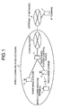
- Fig. 1 is a distribution diagram of a configuration of a mobile packet communication system according to the present invention.
- a mobile communication terminal 1 a radio base station device 2, a radio-base-station control device 3, and a core network 4 constitute a mobile communication network 5.
- the mobile communication network 5 is connected to an external IP network 6, to which an IP terminal 7 is connected.
- CDMA code division multiple access
- Fig. 2 is a functional block diagram of parts that prepare an up-transmission schedule in the mobile communication terminal 1.
- the mobile communication terminal 1 includes an encoding unit 11, a transmission-signal generating unit 12, a radio-signal transmitting unit 13, a reception-signal analyzing unit 14, and a control unit 16.
- the transmission-signal generating unit 12 superposes transmission data encoded by the encoding unit 11, on a predetermined radio-channel control signal to generate a transmission signal.
- the transmission signal is transmitted from the radio-signal transmitting unit 13.
- a radio-signal receiving unit 15 receives a reception signal, which is analyzed by the reception-signal analyzing unit 14.
- the control unit 16 controls these operations.
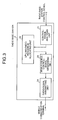
- Fig. 3 is a functional block diagram of parts that prepare the up-transmission schedule in the radio base station 2.
- the radio base station 2 includes a radio-signal analyzing unit 21, an up-link-radio-resource allocating unit 22, a mobile-device-control-signal generating unit 23, and a radio-signal transmitting unit 24.
- a signal input from the radio-base-station control device 3 is a request for setting of a radio channel
- the signal is sent to the up-link-radio-resource allocating unit 22.
- the up-link-radio-resource allocating unit 22 allocates up-link radio resources, that is, performs up-transmission scheduling.
- the obtained up-transmission schedule is sent to the mobile-device-control-signal generating unit 23, by which the schedule is superposed on a predetermined radio-channel control signal to generate a transmission signal.
- the radio-signal transmitting unit 24 transmits the transmission signal to the mobile communication terminal 1.
- the.radio base station 2 for the cell or the sector to which data will be transmitted determines an up-transmission schedule for the mobile communication terminal 1 in the same procedure as establishing the radio channel.
- up-link radio resources are allocated according to the transmission-data basic information so that the transmission data can be continuously transmitted at the codec cycle of the mobile communication terminal 1, thereby accomplishing real-time IP data communications.
- the mobile packet communication system has the radio base station 2 that informs the result of the allocation as a transmission schedule to the mobile communication terminal 1, and the mobile communication terminal 1 that controls the transmission of radio frames according to the up-transmission schedule. Therefore, the mobile communication terminal 1 transmits the real-time IP data through the radio transmission path in an up-communication direction at the codec timing of the mobile communication terminal 1.
- the delay resulting from a radio access is reduced, and the transfer delay between the transmission and reception terminals can be reduced.
- the transmission-data basic information generated by the mobile communication terminal 1 includes the information on a codec start-time determined by the mobile communication terminal 1.
- the up-transmission schedule prepared by the radio base station 2 also includes the codec start-timing of the mobile communication terminal 1. That is, the mobile communication terminal 1 determines the codec start reference time and transmits the transmission-data basic information including this reference time to the radio base station 2 through the radio-base-station control device 3.
- the radio base station 2 generates an up-transmission schedule taking into consideration the codec start-time information. Based on the up-transmission schedule thus generated, the mobile communication terminal 1 controls the transmission of radio frames.
- the mobile communication terminal 1 dominantly determines the codec start-time, thereby providing a timing of starting a stable session.
- the radio-base-station control device 3 adds communication-parameter information representing the service content of the transmission data, to the transmission-data basic information to be transmitted to the radio base station 2. Hence, a further precise codec start-time can be obtained, thereby ensuring a highly reliable transmission operation.
- Fig. 7 is a schematic diagram for explaining determination of an up-transmission schedule from a codec start-time obtained by a backward calculation, which characterizes a mobile packet communication system according to a second embodiment of the present invention.
- the mobile communication terminal 1 determines the codec start-timing based on the transmission schedule prepared by the radio base station 2, on the contrary to the first embodiment.
- the up-transmission schedule acquired through the radio-signal receiving unit 15 and the reception-signal analyzing unit 12 is sent to the control unit 13.
- the control unit 13 controls the encoding unit 11 according to the up-transmission schedule, so that the encoding unit 11 shifts the codec start-timing taking into consideration the process time between a codec-completion timing and a radio-frame transmission, to minimize the delay between the codec completion and the transmission of radio signals. Thereafter, the control unit controls the transmission of the radio-signal transmitting unit 14.
- Fig. 8 is an explanatory diagram of the up-transmission schedule at the time of a hand-over process.
- the radio base station 2 for the cell or the sector to which data will be transmitted determines an up-schedule for the mobile communication terminal 1 in the same procedure as establishing the radio channel.
- the codec start-timing is changed as shown in Fig. 8. Hence, the data under encoding is discarded.
- the mobile communication terminal 1 determines the codec start-timing from the up-transmission schedule in the mobile packet communication system according this embodiment. That is, the transmission-data basic information prepared by the mobile communication terminal 1 does not include information about the start of the codec.
- the mobile communication terminal 1 determines the codec start-timing based on the up-transmission schedule prepared by the radio base station 2.
- the radio base station 2 dominantly determines the codec start-time, thereby further reducing the delay resulting from a radio access.
- the radio base station 2 of the cell or the sector to which data is transmitted prepares an up-transmission schedule in the same procedure as described above. Hence, the delay resulting from a radio access can be reduced, also for the up-transmission of real-time IP data during the hand-over process.
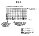
- Fig. 9 is a graph of information relating to radio resource allocation, which characterizes a mobile packet communication system according to a third embodiment of the present invention.
- the present embodiment is characterized by an operation that is performed when a request for retransmission of data is received.
- the mobile communication terminal 1 receives the request for retransmission of data from the radio-base-station control device 3 or the radio base station 2
- this retransmission request is transmitted to the control unit 16 through the radio-signal receiving unit 15 (see Fig. 2) and the radio-signal transmitting unit 14.
- the control unit 13 uses the radio resources of best-effort data, not the real-time data, to control the transmission-signal generating unit 12 and the radio-signal transmitting unit 14, to transmit retransmission data according to the radio resource allocating scheme for best effort (a scheme of determining the timing of transmitting any radio resource not allocated to real-time data from, for example, a random variable).
- the radio resource allocating scheme for best effort a scheme of determining the timing of transmitting any radio resource not allocated to real-time data from, for example, a random variable.
- the mobile communication terminal 1 performs transmission by using the radio resources allocated to each codec cycle, to establish ordinary real-time IP data communications. To transmit the same data again, the mobile communication terminal 1 uses the radio resources allocated for best-effort.
- the radio resource allocating scheme for best effort can prevent a delay in cyclic transmission of the packets due to retransmission of the packets.
- Figs. 10(a) and 10(b) are graphs of radio resource allocation that changes dynamically, which characterize a mobile packet communication system according to a fourth embodiment of the present invention.
- the number of allocated radio resources is plotted on the ordinate, and time is plotted on the abscissa.
- the up-link-radio-resource allocating unit 22 stops allocating the radio resources in which radio frames would be transmitted continuously as shown in Fig. 10(a). Instead, the up-link-radio-resource allocating unit 22 allocates the radio resources again so as to transmit radio transmission frames as shown in Fig. 10(b), by dispersing (averaging) along the time axis. The radio base station 2 then notifies a transmission schedule as the result of radio resource allocation, to the mobile communication terminal 1.
- the up-link-radio-resource allocating unit 22 allocates radio frames again so that radio frames can be transmitted continuously as at the initial stage of transmission. This information is notified to the mobile communication terminal 1. According to this information, the mobile communication terminal 1 transmits radio signals in the same way as in the first embodiment.
- the radio base station 2 performs re-scheduling, preparing a schedule in which up-transmission schedule is averaged along the time axis at the time when the quality of radio transmission is degraded. This can reduces a packet loss resulting from the burst errors made when the quality of radio transmission is degraded.
- Fig. 11 is a flowchart of an operation when radio resource allocation has failed, which characterizes a mobile packet communication system according to a firth embodiment of the present invention.
- the present embodiment is characterized by the process that is performed when the radio resource allocation fails.
- the up-link-radio-resource allocating unit 22 performs the process shown in Fig. 11, not rejecting the allocation of radio resources (step 107 in Fig. 6), when the radio resource allocation fails.
- coefficient N is initialized (step 111 in Fig. 11).
- a radio resource that can transmit a maximum amount of data per cycle time for each up-transmission reference time + N x unit transmission-time or for each codec-cycle time can be secured, it is considered that radio resources have been successfully provisionally allocated, and a corresponding spreading factor is allocated (steps 112, 113, and 114 in Fig. 11).
- the up-link-radio-resource allocating unit 22 rejects the allocation of radio resources (step 117 in Fig. 11).
- a radio resource in which the delay resulting from a radio access can be minimized cannot be allocated, a radio resource in which delay is minimized is allocated from among radio resources that can be allocated in a codec cycle time, and this information is notified to the mobile communication terminal 1.
- the up-link-radio-resource allocating unit 22 allocates this radio resource in place of one of the radio resources that have been provisionally allocated. The up-link-radio-resource allocating unit 22 then notifies this information to the mobile communication terminal 1.
- the mobile communication terminal 1 controls the transmission of radio signals in the same way as in the first embodiment.
- the delay resulting from a radio access can thus be reduced while decreasing the probability of call-reception failure, in the mobile packet communication system according to the present embodiment.
- the radio base station 2 allocates up-link radio resources according to the transmission-data basic information so that data can be transmitted continuously in synchronization with the codec cycle of the mobile communication terminal 1 when real-time IP data communication is performed, in the mobile packet communication system according to this invention.
- the radio base station 2 notifies this information, as an up-transmission schedule, to the mobile communication terminal 1.
- the mobile communication terminal 1 controls the transmission of radio frames based on the transmission schedule. Therefore, the mobile communication terminal 1 transmits IP data to the radio transmission path in an up-direction at the codec timing of the mobile communication terminal 1. This reduces the delay resulting from a radio access and decreases the transfer delay between the transmission and reception terminals.
- the mobile packet communication system employs a radio access scheme such as CDMA, and is suitable for use in the transfer of real-time data required to be handled in real-time, such as audio or moving images, in IP packets.
- a radio access scheme such as CDMA
Landscapes
- Engineering & Computer Science (AREA)
- Quality & Reliability (AREA)
- Computer Networks & Wireless Communication (AREA)
- Signal Processing (AREA)
- Mobile Radio Communication Systems (AREA)
- Data Exchanges In Wide-Area Networks (AREA)
Abstract
Description
- The present invention relates to a mobile packet communication system that employs a radio access scheme such as CDMA, and more particularly, to a scheduling that helps to improve following capability of transmission processing with respect to data required to be processed in real-time.
- At present, studies are underway to provide Internet Protocol (IP) for all mobile communication systems. In such a system, it is expected that real-time data required to be processed in real-time, such as audio data and video data, will be IP-packetized, which can increase a transfer delay between two terminals for transmission and reception, depending on a routing path to be used. It is desirable to reduce the delay in a radio access as much as possible.
- Conventionally, a method in which real-time data and burst data are mixed and subjected to dynamic band-allocation (scheduling) is proposed, in contrast to a time-division radio access scheme. According to this method, priorities are imparted to each of CBR/VBR/ABR classes according to an estimated transmission-completion time (time obtained by adding cycle time to transmission time) and an amount of data to be received before the estimated transmission-completion time. Bands are then allocated in preferential order from transfer data with higher priority (see Patent Document 1).
- Patent Document 1:
Japanese Patent Application Laid-Open No. 2001-223716 - However, in the conventional scheduling method, the priority is calculated from the time based on the cycle time of each service and the amount of reception data, and a service with strict requirements regarding delay will not be preferentially processed. Therefore, the service can be delayed by the cycle time or can fluctuate. In the scheduling method, the estimated transmission-completion time is determined based on reference time adopted in a parent station. Hence, the estimated transmission-completion time is not synchronized with the time when a request is made for data transmission, which can cause a delay.
- The present invention has been achieved to solve the above problems, and an object of the present invention is to provide a mobile packet communication system in which real-time IP data required to be handled in real-time is transmitted from a mobile communication terminal via a radio transmission path, at the codec timing of the mobile communication terminal in an up-transmission from the mobile communication terminal, thereby minimizing the delay resulting from a radio access and reducing transfer delay between transmission and reception terminals.
- A mobile packet communication system according to one aspect of the present invention includes a radio base station that allocates, when performing a real-time Internet-protocol data communication, up-link radio resources, based on basic information of transmission data, so that the transmission data is transmitted in synchronization with a codec cycle of a mobile communication terminal in a concentrated manner, and notifies a result of allocating the up-link radio resources to the mobile communication terminal as an up-transmission schedule; and a mobile communication terminal that controls transmission of a radio frame based on the up-transmission schedule. Therefore, the mobile communication terminal transmits real-time IP data to the radio transmission path in an up-direction at the codec timing of the mobile communication terminal. This reduces the delay resulting from a radio access and decreases the transfer delay between the transmission and reception terminals.
- Furthermore, the basic information of the transmission data includes codec start-time information determined by the mobile communication terminal, and the up-transmission schedule created by the radio base station includes a codec start-timing of the mobile communication terminal. That is, the mobile communication terminal determines a codec start reference time, and transmits transmission-data basic information including codec start-time information which includes the reference time, to the radio base station. The radio base station generates an up-transmission schedule taking into consideration the codec start-time information, at the time of scheduling. The mobile communication terminal controls the transmission of radio frames based on the up-transmission schedule. Thus, the mobile communication terminal dominantly determines the codec start-time, thereby stabilizing session-start timing.
- Alternatively, there is a method in which the mobile communication terminal determines the codec start-timing based on the up-transmission schedule transmitted from the radio base station. That is, instead of including information on the codec start-time in the transmission-data basic information transmitted from the mobile communication terminal to the radio base station, the mobile communication terminal determines the codec start-timing based on the up-transmission schedule prepared by the radio base station. Thus, the radio base station dominantly determines the codec start-time of the mobile communication terminal, thereby further reducing delay due to a radio access.
- Moreover, the mobile communication terminal determines a codec start-timing based on the up-transmission schedule. Therefore, the up-transmission schedule is prepared by taking into consideration data with different configuration depending on the service content. As a result, the codec start-time can be determined more accurately, thereby realizing a highly reliable transmission operation.
-
- Fig. 1 is a distribution diagram of a configuration of a mobile packet communication system according to the present invention;
- Fig. 2 is a functional block diagram of parts that prepare an up-transmission schedule in the mobile communication terminal;
- Fig. 3 is a functional block diagram of parts that prepare an up-transmission schedule in a radio base station;
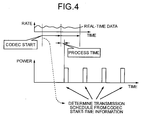
- Fig. 4 is a schematic diagram for explaining a state in which the up-transmission schedule has been determined based on codec start-time information;
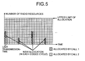
- Fig. 5 is a graph of a state of radio resource allocation according to a first embodiment of the present invention;
- Fig. 6 is a flowchart of an operation of allocating radio resources according to the first embodiment;
- Fig. 7 is a schematic diagram for explaining determination of an up-transmission schedule from a codec start-time obtained by a backward calculation, which characterizes a mobile packet communication system according to a second embodiment of the present invention;
- Fig. 8 is an explanatory diagram of the up-transmission schedule at the time of a hand-over;
- Fig. 9 is a graph of information relating to radio resource allocation, which characterizes a mobile packet communication system according to a third embodiment of the present invention;
- Figs. 10(a) and 10(b) are graphs of a state of radio resource allocation that change dynamically, which characterize a mobile packet communication system according to a fourth embodiment of the present invention;
- Fig. 11 is a flowchart of an operation when radio resource allocation has failed, which characterizes a mobile packet communication system according to a firth embodiment of the present invention; and
- Figs. 12(a) and 12(b) are graphs of a state of reallocation from tentatively allocated radio resources to radio resources initially scheduled to be allocated.
- Exemplary embodiments of a mobile packet communication system according to the present invention will be explained in detail below with reference to the drawings. The present invention is not limited to the embodiments.
- Fig. 1 is a distribution diagram of a configuration of a mobile packet communication system according to the present invention. As shown in Fig. 1, a
mobile communication terminal 1, a radiobase station device 2, a radio-base-station control device 3, and a core network 4 constitute amobile communication network 5. Themobile communication network 5 is connected to anexternal IP network 6, to which an IP terminal 7 is connected. Assume that the present embodiment employs the code division multiple access (CDMA) as a radio access scheme. - Fig. 2 is a functional block diagram of parts that prepare an up-transmission schedule in the
mobile communication terminal 1. As shown in Fig. 2, themobile communication terminal 1 includes anencoding unit 11, a transmission-signal generatingunit 12, a radio-signal transmitting unit 13, a reception-signal analyzing unit 14, and acontrol unit 16. In themobile communication terminal 1, the transmission-signal generatingunit 12 superposes transmission data encoded by theencoding unit 11, on a predetermined radio-channel control signal to generate a transmission signal. The transmission signal is transmitted from the radio-signal transmittingunit 13. A radio-signal receiving unit 15 receives a reception signal, which is analyzed by the reception-signal analyzingunit 14. Thecontrol unit 16 controls these operations. - Fig. 3 is a functional block diagram of parts that prepare the up-transmission schedule in the
radio base station 2. As shown in Fig. 3, theradio base station 2 includes a radio-signal analyzing unit 21, an up-link-radio-resource allocating unit 22, a mobile-device-control-signal generatingunit 23, and a radio-signal transmitting unit 24. When a signal input from the radio-base-station control device 3 is a request for setting of a radio channel, the signal is sent to the up-link-radio-resource allocating unit 22. The up-link-radio-resource allocating unit 22 allocates up-link radio resources, that is, performs up-transmission scheduling. The obtained up-transmission schedule is sent to the mobile-device-control-signal generatingunit 23, by which the schedule is superposed on a predetermined radio-channel control signal to generate a transmission signal. The radio-signal transmittingunit 24 transmits the transmission signal to themobile communication terminal 1. - Operation will be explained next. An example in which a session of real-time IP data communications is performed between the
mobile communication terminal 1 and the IP terminal 7 will be explained. - (1) Generation of Transmission Data Basic Information in Mobile Communication Terminal
An operation from generation of up-transmission data basic information in themobile communication terminal 1 to notification of the information to the radio-base-station control device will be explained.
When a session of real-time IP data communications is started with an input operation by an operator as a trigger, the control unit 16 (see Fig. 2) recognizes that a procedure of establishing a radio channel for the real-time IP data communications has started. Thecontrol unit 16 requests theencoding unit 11 to determine the start timing of codec. Upon receiving the codec start-timing determination request, theencoding unit 11 determines the time to be the basis of starting the codec and sends this time information to thecontrol unit 16. Thecontrol unit 16 adds a predetermined processing time to this codec start reference time, thus calculating an up-transmission start reference time, which is sent to the transmission-signal generating unit 12. The predetermined processing time is the processing time from the codec-completion timing that is held as inherent information to transmission of a radio frame, in themobile communication terminal 1.
The up-transmission start reference time sent to the transmission-signal generating unit 12 is superposed on a radio-channel control signal and used as a part of quality-of-service (QoS) information. The up-transmission start reference time is then transmitted from the radio-signal transmitting unit 13 to the radio-base-station control device 3 via theradio base station 2.
The up-transmission basic information can be generated in themobile communication terminal 1 and can be notified to the radio-base-station control device 3, in the following method. That is, thecontrol unit 16 recognizes that a procedure of establishing a radio channel has started, and requests theencoding unit 11 to determine the codec start-timing. Theencoding unit 11, which has received the codec start-timing determination request, performs codec on dummy data until a radio channel is established for the real-time IP data. Theencoding unit 11 sends the generated IP packet to the transmission-signal generating unit 12. The transmission-signal generating unit 12 recognizes the time at which it receives the IP packet, as the codec start reference time. The transmission-signal generating unit 12 adds a predetermined processing time to the codec start reference time, thus calculating an up-transmission start reference time. At the same time, the transmission-signal generating unit 12 discards the dummy data. The transmission-signal generating unit 12 superposes the up-transmission reference time as a part of QoS information, on a radio-channel control signal. The up-transmission start reference time is transmitted from the radio-signal transmitting unit 13 to the radio-base-station control device 3 via theradio base station 2. - (2) Radio-Channel Setting Request from the Radio-base-
station control device 3 to theRadio Base Station 2
The radio-base-station control device 3 receives transmission reference time information from themobile communication terminal 1. The radio-base-station control device 3 then writes, as a part of QoS information, this information, the codec cycle time for the session, communication type, and information on a maximum amount of data transmitted per codec-cycle time from themobile communication terminal 1 in a direction (up) to theradio base station 2. The radio-base-station control device 3 then transmits a radio-channel setting request including the QoS information to theradio base station 2. - (3) Allocation of Up-Link Radio Resources in the
Radio Base Station 2
A method of allocating up-link radio resources of theradio base station 2 when theradio base station 2 receives a radio-channel setting request from the radio-base-station control device 3, and a method of informing an up-link schedule to themobile communication terminal 1 are explained.
The control-signal analyzing unit 21 (see Fig. 3), having received the radio-channel setting request from the radio-base-station control device 3, sends the QoS information to the up-link-radio-resource allocating unit 22. The up-link-radio-resource allocating unit 22 determines, from the QoS information, whether the communication type is included in the real-time IP data communications. If the communication type is included in the real-time IP data communications, the up-link-radio-resource allocating unit 22 prepares an up-transmission schedule for transmitting radio frames continuously at the codec timing of themobile communication terminal 1.
Fig. 4 is a schematic diagram for explaining a state in which the up-transmission schedule has been determined based on codec start-time information. As shown in Fig. 4, the up-link-radio-resource allocating unit 22 allocates radio resources based on the QoS information so that radio frames can be transmitted continuously at the codec timing of themobile communication terminal 1. That is, the up-link-radio-resource allocating unit 22 allocates the radio resources continuously during each codec-cycle time until the call is released. An up-transmission schedule obtained by the allocation (including the time for which transmission can be performed, spreading factors, and the like) is transmitted from the mobile-device-control-signal generating unit 23 to themobile communication terminal 1 via the radio-signal transmitting unit 24.
The radio resource allocation operation by the up-link-radio-resource allocating unit 22 will be explained in detail.
Fig. 5 is a graph of radio resource allocation. The number of allocated radio resources is plotted on the ordinate, and time is plotted on the abscissa. Fig. 6 is a flowchart of the operation of allocating radio resources.
Theradio base station 2 manages the allocation of radio resources during each of a unit transmission-time of the up-transmission schedule as shown in Fig. 5. When a new request is made for allocation of radio resources, theradio base station 2 corrects the up-transmission reference time based on the unit transmission-time (step 101 in Fig. 6). The condition of "up-transmission reference time valid before correction" < "up-transmission reference time valid after correction" is applied herein. To meet this condition, the codec-cycle time is repeatedly added if the transmission reference time valid before the correction is less than the time during which up-radio resources can be allocated at present in theradio base station 2, that is, if the above inequality is satisfied (namely, if "up-transmission reference time valid after correction" < "time when allocation can be performed") (steps 102 and 103 in Fig. 6).
If any radio resource that can transmit a large amount of data for one cycle time at the up-transmission reference time valid after recorrection and at a predetermined codec cycle timing is secured (limit of radio resources is determined based on a total value of interference power in the radio base station 2), theradio base station 2 allocates a spreading factor corresponding to the radio resource, indicating that the radio resources have been successfully allocated (steps 104, 105, and 106 in Fig. 6).
If no such radio resources are secured (if NO at steps 104 and 105 in Fig. 6), theradio base station 2 does not allocate radio resources, indicating that the radio resources have not been successfully allocated (step 107 in Fig. 6). - (4) Control of Up-Transmission in the
Mobile Communication Terminal 1
Up-transmission control in themobile communication terminal 1 that has received the up-transmission schedule is explained next. In themobile communication terminal 1, the up-transmission schedule acquired through the radio-signal receiving unit 15 (see Fig. 2) and the reception-signal analyzing unit 14 is sent to thecontrol unit 13. The control unit controls transmission of the radio-signal transmitting unit 14 according to the received transmission schedule. - When the
mobile communication terminal 1 performs hand-over process to any other cell or a sector, the.radio base station 2 for the cell or the sector to which data will be transmitted determines an up-transmission schedule for themobile communication terminal 1 in the same procedure as establishing the radio channel. - Thus, in the mobile packet communication system according to this embodiment, up-link radio resources are allocated according to the transmission-data basic information so that the transmission data can be continuously transmitted at the codec cycle of the
mobile communication terminal 1, thereby accomplishing real-time IP data communications. The mobile packet communication system has theradio base station 2 that informs the result of the allocation as a transmission schedule to themobile communication terminal 1, and themobile communication terminal 1 that controls the transmission of radio frames according to the up-transmission schedule. Therefore, themobile communication terminal 1 transmits the real-time IP data through the radio transmission path in an up-communication direction at the codec timing of themobile communication terminal 1. Thus, the delay resulting from a radio access is reduced, and the transfer delay between the transmission and reception terminals can be reduced. - The transmission-data basic information generated by the
mobile communication terminal 1 includes the information on a codec start-time determined by themobile communication terminal 1. The up-transmission schedule prepared by theradio base station 2 also includes the codec start-timing of themobile communication terminal 1. That is, themobile communication terminal 1 determines the codec start reference time and transmits the transmission-data basic information including this reference time to theradio base station 2 through the radio-base-station control device 3. Theradio base station 2 generates an up-transmission schedule taking into consideration the codec start-time information. Based on the up-transmission schedule thus generated, themobile communication terminal 1 controls the transmission of radio frames. Thus, themobile communication terminal 1 dominantly determines the codec start-time, thereby providing a timing of starting a stable session. - The radio-base-
station control device 3 adds communication-parameter information representing the service content of the transmission data, to the transmission-data basic information to be transmitted to theradio base station 2. Hence, a further precise codec start-time can be obtained, thereby ensuring a highly reliable transmission operation. - Fig. 7 is a schematic diagram for explaining determination of an up-transmission schedule from a codec start-time obtained by a backward calculation, which characterizes a mobile packet communication system according to a second embodiment of the present invention.
- In the present embodiment, the
mobile communication terminal 1 determines the codec start-timing based on the transmission schedule prepared by theradio base station 2, on the contrary to the first embodiment. - Flow of the up-transmission scheduling process by the
mobile communication terminal 1, in cooperation with theradio base station 2 will be explained. - (1) Radio-Channel Setting Request from the Radio-base-
station control device 3 to theRadio Base Station 2
To initiate a session of real-time IP data communication between, for example, themobile communication terminal 1 and the IP terminal 7, the radio-base-station control device 3 writes, as a part of QoS information, the codec-cycle time for the session, the communication type, and information on a maximum amount of data transmitted per codec-cycle time from themobile communication terminal 1 in a direction (up) to theradio base station 2. The radio-base-station control device 3 then transmits a radio-channel setting request including the QoS information to theradio base station 2. - (2) Allocation of Up-Link Radio Resources in the
Radio Base Station 2
The control-signal analyzing unit 21 (see Fig. 3), having received the radio-channel setting request from the radio-base-station control device 3, sends the QoS information to the up-link-radio-resource allocating unit 22. The up-link-radio-resource allocating unit 22 determines, from the QoS information, whether the communication type is included in the real-time IP data communications. If the communication type is included in the real-time IP data communications, the up-link-radio-resource allocating unit 22 allocates the radio frames continuously during each codec-cycle time until the call is released. (That is, a transmission reference time at which cycles can be allocated in theradio base station 2 is determined). An up-transmission schedule is thus obtained by the allocation is transmitted to themobile communication terminal 1 via the mobile-device-control-signal generating unit 23 and the radio-signal transmitting unit 24. - (3) Control of Up-Transmission in the
Mobile Communication Terminal 1 - Up-transmission control in the
mobile communication terminal 1 that has received the up-transmission schedule will be explained. In themobile communication terminal 1, the up-transmission schedule acquired through the radio-signal receiving unit 15 and the reception-signal analyzing unit 12 is sent to thecontrol unit 13. Thecontrol unit 13 controls theencoding unit 11 according to the up-transmission schedule, so that theencoding unit 11 shifts the codec start-timing taking into consideration the process time between a codec-completion timing and a radio-frame transmission, to minimize the delay between the codec completion and the transmission of radio signals. Thereafter, the control unit controls the transmission of the radio-signal transmitting unit 14. - Fig. 8 is an explanatory diagram of the up-transmission schedule at the time of a hand-over process. When the
mobile communication terminal 1 performs a hand-over process to any other cell or a sector, theradio base station 2 for the cell or the sector to which data will be transmitted determines an up-schedule for themobile communication terminal 1 in the same procedure as establishing the radio channel. At this time, the codec start-timing is changed as shown in Fig. 8. Hence, the data under encoding is discarded. - Thus, the
mobile communication terminal 1 determines the codec start-timing from the up-transmission schedule in the mobile packet communication system according this embodiment. That is, the transmission-data basic information prepared by themobile communication terminal 1 does not include information about the start of the codec. Themobile communication terminal 1 determines the codec start-timing based on the up-transmission schedule prepared by theradio base station 2. Thus, theradio base station 2 dominantly determines the codec start-time, thereby further reducing the delay resulting from a radio access. - At the time of the hand-over process, the
radio base station 2 of the cell or the sector to which data is transmitted, prepares an up-transmission schedule in the same procedure as described above. Hence, the delay resulting from a radio access can be reduced, also for the up-transmission of real-time IP data during the hand-over process. - Fig. 9 is a graph of information relating to radio resource allocation, which characterizes a mobile packet communication system according to a third embodiment of the present invention. The present embodiment is characterized by an operation that is performed when a request for retransmission of data is received. When the
mobile communication terminal 1 receives the request for retransmission of data from the radio-base-station control device 3 or theradio base station 2, this retransmission request is transmitted to thecontrol unit 16 through the radio-signal receiving unit 15 (see Fig. 2) and the radio-signal transmitting unit 14. - As shown in Fig. 9, the
control unit 13 uses the radio resources of best-effort data, not the real-time data, to control the transmission-signal generating unit 12 and the radio-signal transmitting unit 14, to transmit retransmission data according to the radio resource allocating scheme for best effort (a scheme of determining the timing of transmitting any radio resource not allocated to real-time data from, for example, a random variable). - Thus, in the mobile packet communication system according to this embodiment, the
mobile communication terminal 1 performs transmission by using the radio resources allocated to each codec cycle, to establish ordinary real-time IP data communications. To transmit the same data again, themobile communication terminal 1 uses the radio resources allocated for best-effort. The radio resource allocating scheme for best effort can prevent a delay in cyclic transmission of the packets due to retransmission of the packets. - Figs. 10(a) and 10(b) are graphs of radio resource allocation that changes dynamically, which characterize a mobile packet communication system according to a fourth embodiment of the present invention. The number of allocated radio resources is plotted on the ordinate, and time is plotted on the abscissa.
- In the first embodiment, if the
radio base station 2 determines that the up-link radio transmission of data from themobile communication terminal 1 has been degraded, the up-link-radio-resource allocating unit 22 stops allocating the radio resources in which radio frames would be transmitted continuously as shown in Fig. 10(a). Instead, the up-link-radio-resource allocating unit 22 allocates the radio resources again so as to transmit radio transmission frames as shown in Fig. 10(b), by dispersing (averaging) along the time axis. Theradio base station 2 then notifies a transmission schedule as the result of radio resource allocation, to themobile communication terminal 1. - When the quality of radio transmission restores, the up-link-radio-
resource allocating unit 22 allocates radio frames again so that radio frames can be transmitted continuously as at the initial stage of transmission. This information is notified to themobile communication terminal 1. According to this information, themobile communication terminal 1 transmits radio signals in the same way as in the first embodiment. - In the mobile packet communication system according to the present embodiment, the
radio base station 2 performs re-scheduling, preparing a schedule in which up-transmission schedule is averaged along the time axis at the time when the quality of radio transmission is degraded. This can reduces a packet loss resulting from the burst errors made when the quality of radio transmission is degraded. - Fig. 11 is a flowchart of an operation when radio resource allocation has failed, which characterizes a mobile packet communication system according to a firth embodiment of the present invention.
- The present embodiment is characterized by the process that is performed when the radio resource allocation fails. In the first and the fourth embodiments, the up-link-radio-
resource allocating unit 22 performs the process shown in Fig. 11, not rejecting the allocation of radio resources (step 107 in Fig. 6), when the radio resource allocation fails. - First, coefficient N is initialized (step 111 in Fig. 11). When a radio resource that can transmit a maximum amount of data per cycle time for each up-transmission reference time + N x unit transmission-time or for each codec-cycle time can be secured, it is considered that radio resources have been successfully provisionally allocated, and a corresponding spreading factor is allocated (steps 112, 113, and 114 in Fig. 11).
- If such a radio resource is not secured and if N x unit transmission-time < codec cycle, the coefficient N is set to N+1. The process then returns to step 112 (step 116 in Fig. 11). Otherwise, the up-link-radio-
resource allocating unit 22 rejects the allocation of radio resources (step 117 in Fig. 11). - In the present embodiment, if it is determined that a radio resource in which the delay resulting from a radio access can be minimized cannot be allocated, a radio resource in which delay is minimized is allocated from among radio resources that can be allocated in a codec cycle time, and this information is notified to the
mobile communication terminal 1. - When any radio resource that is to be allocated initially and that is being used by another call is released, the up-link-radio-
resource allocating unit 22 allocates this radio resource in place of one of the radio resources that have been provisionally allocated. The up-link-radio-resource allocating unit 22 then notifies this information to themobile communication terminal 1. - According to the up-transmission schedule thus updated, the
mobile communication terminal 1 controls the transmission of radio signals in the same way as in the first embodiment. - The delay resulting from a radio access can thus be reduced while decreasing the probability of call-reception failure, in the mobile packet communication system according to the present embodiment.
- As described in the first to the fifth embodiments, the
radio base station 2 allocates up-link radio resources according to the transmission-data basic information so that data can be transmitted continuously in synchronization with the codec cycle of themobile communication terminal 1 when real-time IP data communication is performed, in the mobile packet communication system according to this invention. Theradio base station 2 notifies this information, as an up-transmission schedule, to themobile communication terminal 1. Themobile communication terminal 1 controls the transmission of radio frames based on the transmission schedule. Therefore, themobile communication terminal 1 transmits IP data to the radio transmission path in an up-direction at the codec timing of themobile communication terminal 1. This reduces the delay resulting from a radio access and decreases the transfer delay between the transmission and reception terminals. - As explained above, the mobile packet communication system according to the present invention employs a radio access scheme such as CDMA, and is suitable for use in the transfer of real-time data required to be handled in real-time, such as audio or moving images, in IP packets.
Claims (9)
- A mobile packet communication system comprising:a radio base station that allocates, when performing a real-time Internet-protocol data communication, up-link radio resources, based on basic information of transmission data, so that the transmission data is transmitted in synchronization with a codec cycle of a mobile communication terminal in a concentrated manner, and notifies a result of allocating the up-link radio resources to the mobile communication terminal as an up-transmission schedule; anda mobile communication terminal that controls transmission of a radio frame based on the up-transmission schedule.
- The mobile packet communication system according to claim 1, wherein
the basic information of the transmission data includes codec start-time information determined by the mobile communication terminal, and
the up-transmission schedule created by the radio base station includes a codec start-timing of the mobile communication terminal. - The mobile packet communication system according to claim 1, wherein
the mobile communication terminal determines a codec start-timing based on the up-transmission schedule. - The mobile packet communication system according to claim 1, wherein
service-content-dependent communication-parameter information of the transmission data is added to the basic information of the transmission data by a radio-base-station control device. - The mobile packet communication system according to claim 1, wherein
when a handover is being performed, a radio base station of a cell or a sector of a destination creates the up-transmission schedule. - The mobile packet communication system according to claim 1, wherein
the mobile communication terminal perform the transmission by using radio resources allocated to each codec cycle, and when performing a re-transmission, perform the transmission by using radio resources allocated for best effort. - The mobile packet communication system according to claim 1, wherein
the radio base station performs a re-scheduling, when radio quality is degraded, by time-averaging the up-transmission schedule. - The mobile packet communication system according to claim 1, wherein
the radio base station allocates a radio resource that minimizes occurrence of a delay. - The mobile packet communication system according to claim 1, wherein
when a radio resource with less delay than a radio resource allocated at present is released, the radio base station changes the radio resource to the radio resource with less delay.
Applications Claiming Priority (1)
| Application Number | Priority Date | Filing Date | Title |
|---|---|---|---|
| PCT/JP2004/007324 WO2005115041A1 (en) | 2004-05-21 | 2004-05-21 | Mobile packet communication system |
Publications (2)
| Publication Number | Publication Date |
|---|---|
| EP1750468A1 true EP1750468A1 (en) | 2007-02-07 |
| EP1750468A4 EP1750468A4 (en) | 2009-02-18 |
Family
ID=35428696
Family Applications (1)
| Application Number | Title | Priority Date | Filing Date |
|---|---|---|---|
| EP04734391A Withdrawn EP1750468A4 (en) | 2004-05-21 | 2004-05-21 | MOBILE PACKET COMMUNICATIONS SYSTEM |
Country Status (5)
| Country | Link |
|---|---|
| US (1) | US7672292B2 (en) |
| EP (1) | EP1750468A4 (en) |
| JP (1) | JP4343224B2 (en) |
| CN (1) | CN1954630A (en) |
| WO (1) | WO2005115041A1 (en) |
Cited By (4)
| Publication number | Priority date | Publication date | Assignee | Title |
|---|---|---|---|---|
| EP2364053A1 (en) * | 2008-09-22 | 2011-09-07 | HTC Corporation | Method and related device for synchronizing semi-persistent scheduling data delivery and semi-persistent scheduling resource arrival in a wireless communication system |
| CN103392370A (en) * | 2011-01-20 | 2013-11-13 | 高通股份有限公司 | Method and apparatus to facilitate support for multi-radio coexistence |
| EP2124469A4 (en) * | 2007-03-01 | 2014-07-30 | Ntt Docomo Inc | BASE STATION DEVICE AND METHOD FOR CONTROLLING COMMUNICATION |
| EP2127148A4 (en) * | 2007-03-23 | 2014-10-15 | Samsung Electronics Co Ltd | METHOD AND SYSTEM FOR PROGRAMMING IN MOBILE COMMUNICATION SYSTEM |
Families Citing this family (9)
| Publication number | Priority date | Publication date | Assignee | Title |
|---|---|---|---|---|
| DE202005021930U1 (en) * | 2005-08-01 | 2011-08-08 | Corning Cable Systems Llc | Fiber optic decoupling cables and pre-connected assemblies with toning parts |
| RU2009134937A (en) | 2007-03-01 | 2011-04-10 | НТТ ДоСоМо, Инк. (JP) | BASIC STATION AND COMMUNICATION MANAGEMENT METHOD |
| CN101669395A (en) | 2007-03-01 | 2010-03-10 | 株式会社Ntt都科摩 | Base station apparatus and communication control method |
| US8391219B2 (en) | 2007-03-01 | 2013-03-05 | Ntt Docomo, Inc. | Base station apparatus and communication control method |
| CN101669382B (en) | 2007-03-01 | 2014-02-12 | 株式会社Ntt都科摩 | Base station device and communication control method |
| KR20090118074A (en) * | 2007-03-01 | 2009-11-17 | 가부시키가이샤 엔티티 도코모 | Base station equipment and communication control method |
| BRPI0808393A2 (en) | 2007-03-01 | 2014-07-08 | Ntt Docomo Inc | BASE STATION APPARATUS AND COMMUNICATION CONTROL METHOD. |
| EP2712257B1 (en) * | 2012-09-24 | 2014-11-05 | Alcatel Lucent | Apparatus, method and computer program for scheduling data transmission |
| CN111125241B (en) * | 2018-10-31 | 2023-10-20 | 伊姆西Ip控股有限责任公司 | Methods, devices and computer storage media for data synchronization |
Family Cites Families (12)
| Publication number | Priority date | Publication date | Assignee | Title |
|---|---|---|---|---|
| US4924480A (en) * | 1988-03-11 | 1990-05-08 | American Telephone And Telegraph Company | Codecs with suppression of multiple encoding/decodings across a connection |
| SE515901C2 (en) * | 1995-12-28 | 2001-10-22 | Dynarc Ab | Resource management, plans and arrangements |
| JP4588201B2 (en) | 1999-11-29 | 2010-11-24 | パナソニック株式会社 | Wireless communication system |
| JP3594076B2 (en) * | 2000-03-01 | 2004-11-24 | 日本電気株式会社 | Packet switch and scheduling method thereof |
| EP1209936A1 (en) | 2000-11-22 | 2002-05-29 | Lucent Technologies Inc. | Method and system for UMTS packet transmission scheduling on shared downlink channels |
| EP1209940A1 (en) | 2000-11-22 | 2002-05-29 | Lucent Technologies Inc. | Method and system for UMTS packet transmission scheduling on uplink channels |
| FI110734B (en) * | 2001-03-16 | 2003-03-14 | Nokia Corp | Channel codec test loops |
| US6647273B2 (en) * | 2001-12-28 | 2003-11-11 | Nokia Corporation | Method and apparatus for reducing power consumption in transceivers in wireless communications systems having a power control loop |
| JP3823061B2 (en) * | 2002-03-13 | 2006-09-20 | 祐二 尾家 | Wireless communication apparatus and wireless packet communication method |
| EP1347581A3 (en) * | 2002-03-22 | 2004-11-17 | Kabushiki Kaisha Toshiba | Radio communication apparatus and method |
| JP3914844B2 (en) * | 2002-08-22 | 2007-05-16 | 日本電気株式会社 | Non-instantaneous hard handover control apparatus and method |
| US7339948B2 (en) * | 2003-01-22 | 2008-03-04 | Rockwell Automation Technologies, Inc. | Industrial controller providing deterministic communication on ethernet |
-
2004
- 2004-05-21 WO PCT/JP2004/007324 patent/WO2005115041A1/en not_active Ceased
- 2004-05-21 EP EP04734391A patent/EP1750468A4/en not_active Withdrawn
- 2004-05-21 JP JP2006513663A patent/JP4343224B2/en not_active Expired - Fee Related
- 2004-05-21 US US11/596,669 patent/US7672292B2/en not_active Expired - Fee Related
- 2004-05-21 CN CNA2004800429632A patent/CN1954630A/en active Pending
Cited By (7)
| Publication number | Priority date | Publication date | Assignee | Title |
|---|---|---|---|---|
| EP2124469A4 (en) * | 2007-03-01 | 2014-07-30 | Ntt Docomo Inc | BASE STATION DEVICE AND METHOD FOR CONTROLLING COMMUNICATION |
| EP2127148A4 (en) * | 2007-03-23 | 2014-10-15 | Samsung Electronics Co Ltd | METHOD AND SYSTEM FOR PROGRAMMING IN MOBILE COMMUNICATION SYSTEM |
| US9504064B2 (en) | 2007-03-23 | 2016-11-22 | Samsung Electronics Co., Ltd. | Method and system for scheduling in mobile communication system |
| EP2364053A1 (en) * | 2008-09-22 | 2011-09-07 | HTC Corporation | Method and related device for synchronizing semi-persistent scheduling data delivery and semi-persistent scheduling resource arrival in a wireless communication system |
| US9167594B2 (en) | 2008-09-22 | 2015-10-20 | Htc Corporation | Method and related device of a trigger mechanism of buffer status report and scheduling request in a wireless communication system |
| CN103392370A (en) * | 2011-01-20 | 2013-11-13 | 高通股份有限公司 | Method and apparatus to facilitate support for multi-radio coexistence |
| CN103392370B (en) * | 2011-01-20 | 2018-01-26 | 高通股份有限公司 | Method and apparatus for helping to support multi-radio coexistence |
Also Published As
| Publication number | Publication date |
|---|---|
| CN1954630A (en) | 2007-04-25 |
| US20070242640A1 (en) | 2007-10-18 |
| JPWO2005115041A1 (en) | 2008-03-27 |
| EP1750468A4 (en) | 2009-02-18 |
| JP4343224B2 (en) | 2009-10-14 |
| WO2005115041A1 (en) | 2005-12-01 |
| US7672292B2 (en) | 2010-03-02 |
Similar Documents
| Publication | Publication Date | Title |
|---|---|---|
| KR100879613B1 (en) | Non-scheduled transmission method and apparatus for packet service in mobile communication system | |
| US7672292B2 (en) | Mobile packet communication system | |
| KR20110039160A (en) | Method and apparatus for transmitting scheduling request signal in mobile communication system | |
| JP2002511672A (en) | Flexible radio access and resource allocation in Universal Mobile Telephone System (UMTS) | |
| EP2254384B1 (en) | Signalling scheduling assitance data in a cellular communication system | |
| EP3491869B1 (en) | Techniques for adaptive transmissions during urllc | |
| US20080176576A1 (en) | Fast Indication of Uplink Voice Activity | |
| WO2009075485A1 (en) | Apparatus and method for random access based on call priority in a mobile communication system | |
| CN104823507B (en) | The means of communication and equipment | |
| EP1034642B1 (en) | Telecommunication system with channel sharing | |
| US8369273B2 (en) | Method and apparatus for discriminating between control messages and speech payload | |
| US20050221850A1 (en) | Dynamic identifier allotting method and wireless communications system | |
| US12316459B2 (en) | Communication system | |
| CA2581460C (en) | Resource allocation in a communication system | |
| KR100783045B1 (en) | Data transmission method, system, base station, subscriber station, data processing unit, computer program distribution medium and baseband module | |
| US20090207787A1 (en) | Radio base station, control apparatus, and wireless communication method | |
| US10887061B2 (en) | Systems and methods for packet segmentation in standalone small cell | |
| JP2005101815A (en) | Mobile communication terminal | |
| EP1867184B1 (en) | A method, an apparatus and a system for uplink establishment in a wireless cellular communication having a delay dependent on connection type | |
| KR20070084396A (en) | Mobile communication systems, mobile stations and wireless base stations | |
| Huang et al. | A QoS architecture for IDMA-based multi-service wireless networks | |
| KR100846025B1 (en) | Mobile packet communication system | |
| EP1684473A1 (en) | Method of management of multiple uplink tbfs in gprs systems | |
| KR20060091559A (en) | Non-scheduled data transmission / reception method of reverse link in mobile communication system | |
| CN121220101A (en) | Data processing methods and wireless communication devices |
Legal Events
| Date | Code | Title | Description |
|---|---|---|---|
| PUAI | Public reference made under article 153(3) epc to a published international application that has entered the european phase |
Free format text: ORIGINAL CODE: 0009012 |
|
| 17P | Request for examination filed |
Effective date: 20060922 |
|
| AK | Designated contracting states |
Kind code of ref document: A1 Designated state(s): DE FR GB |
|
| DAX | Request for extension of the european patent (deleted) | ||
| RBV | Designated contracting states (corrected) |
Designated state(s): DE FR GB |
|
| A4 | Supplementary search report drawn up and despatched |
Effective date: 20090121 |
|
| 17Q | First examination report despatched |
Effective date: 20110323 |
|
| RIC1 | Information provided on ipc code assigned before grant |
Ipc: H04B 1/707 20110101ALI20110830BHEP Ipc: H04W 72/12 20090101AFI20110830BHEP |
|
| GRAP | Despatch of communication of intention to grant a patent |
Free format text: ORIGINAL CODE: EPIDOSNIGR1 |
|
| STAA | Information on the status of an ep patent application or granted ep patent |
Free format text: STATUS: THE APPLICATION HAS BEEN WITHDRAWN |
|
| 18W | Application withdrawn |
Effective date: 20120412 |