EP1750169A2 - Liquid crystal display with differently-colored localized display areas - Google Patents
Liquid crystal display with differently-colored localized display areas Download PDFInfo
- Publication number
- EP1750169A2 EP1750169A2 EP06076337A EP06076337A EP1750169A2 EP 1750169 A2 EP1750169 A2 EP 1750169A2 EP 06076337 A EP06076337 A EP 06076337A EP 06076337 A EP06076337 A EP 06076337A EP 1750169 A2 EP1750169 A2 EP 1750169A2
- Authority
- EP
- European Patent Office
- Prior art keywords
- light sources
- color
- light
- liquid crystal
- crystal display
- Prior art date
- Legal status (The legal status is an assumption and is not a legal conclusion. Google has not performed a legal analysis and makes no representation as to the accuracy of the status listed.)
- Withdrawn
Links
- 239000004973 liquid crystal related substance Substances 0.000 title claims abstract description 34
- 238000005286 illumination Methods 0.000 claims abstract description 8
- 210000002858 crystal cell Anatomy 0.000 claims description 13
- 239000000463 material Substances 0.000 claims description 12
- 239000003086 colorant Substances 0.000 claims description 8
- 239000007787 solid Substances 0.000 claims description 2
- 230000001902 propagating effect Effects 0.000 claims 1
- 238000000034 method Methods 0.000 description 5
- 238000004378 air conditioning Methods 0.000 description 2
- 238000010438 heat treatment Methods 0.000 description 2
- 230000003287 optical effect Effects 0.000 description 2
- 230000007704 transition Effects 0.000 description 2
- 238000009423 ventilation Methods 0.000 description 2
- 238000011109 contamination Methods 0.000 description 1
- 238000007796 conventional method Methods 0.000 description 1
- 230000004069 differentiation Effects 0.000 description 1
- 238000002955 isolation Methods 0.000 description 1
- 238000004519 manufacturing process Methods 0.000 description 1
- 230000000644 propagated effect Effects 0.000 description 1
- 238000000926 separation method Methods 0.000 description 1
Images

Classifications
-
- G—PHYSICS
- G02—OPTICS
- G02F—OPTICAL DEVICES OR ARRANGEMENTS FOR THE CONTROL OF LIGHT BY MODIFICATION OF THE OPTICAL PROPERTIES OF THE MEDIA OF THE ELEMENTS INVOLVED THEREIN; NON-LINEAR OPTICS; FREQUENCY-CHANGING OF LIGHT; OPTICAL LOGIC ELEMENTS; OPTICAL ANALOGUE/DIGITAL CONVERTERS
- G02F1/00—Devices or arrangements for the control of the intensity, colour, phase, polarisation or direction of light arriving from an independent light source, e.g. switching, gating or modulating; Non-linear optics
- G02F1/01—Devices or arrangements for the control of the intensity, colour, phase, polarisation or direction of light arriving from an independent light source, e.g. switching, gating or modulating; Non-linear optics for the control of the intensity, phase, polarisation or colour
- G02F1/13—Devices or arrangements for the control of the intensity, colour, phase, polarisation or direction of light arriving from an independent light source, e.g. switching, gating or modulating; Non-linear optics for the control of the intensity, phase, polarisation or colour based on liquid crystals, e.g. single liquid crystal display cells
- G02F1/133—Constructional arrangements; Operation of liquid crystal cells; Circuit arrangements
- G02F1/1333—Constructional arrangements; Manufacturing methods
- G02F1/1335—Structural association of cells with optical devices, e.g. polarisers or reflectors
- G02F1/1336—Illuminating devices
- G02F1/133621—Illuminating devices providing coloured light
-
- G—PHYSICS
- G02—OPTICS
- G02F—OPTICAL DEVICES OR ARRANGEMENTS FOR THE CONTROL OF LIGHT BY MODIFICATION OF THE OPTICAL PROPERTIES OF THE MEDIA OF THE ELEMENTS INVOLVED THEREIN; NON-LINEAR OPTICS; FREQUENCY-CHANGING OF LIGHT; OPTICAL LOGIC ELEMENTS; OPTICAL ANALOGUE/DIGITAL CONVERTERS
- G02F1/00—Devices or arrangements for the control of the intensity, colour, phase, polarisation or direction of light arriving from an independent light source, e.g. switching, gating or modulating; Non-linear optics
- G02F1/01—Devices or arrangements for the control of the intensity, colour, phase, polarisation or direction of light arriving from an independent light source, e.g. switching, gating or modulating; Non-linear optics for the control of the intensity, phase, polarisation or colour
- G02F1/13—Devices or arrangements for the control of the intensity, colour, phase, polarisation or direction of light arriving from an independent light source, e.g. switching, gating or modulating; Non-linear optics for the control of the intensity, phase, polarisation or colour based on liquid crystals, e.g. single liquid crystal display cells
- G02F1/133—Constructional arrangements; Operation of liquid crystal cells; Circuit arrangements
- G02F1/1333—Constructional arrangements; Manufacturing methods
- G02F1/133391—Constructional arrangement for sub-divided displays
-
- G—PHYSICS
- G02—OPTICS
- G02F—OPTICAL DEVICES OR ARRANGEMENTS FOR THE CONTROL OF LIGHT BY MODIFICATION OF THE OPTICAL PROPERTIES OF THE MEDIA OF THE ELEMENTS INVOLVED THEREIN; NON-LINEAR OPTICS; FREQUENCY-CHANGING OF LIGHT; OPTICAL LOGIC ELEMENTS; OPTICAL ANALOGUE/DIGITAL CONVERTERS
- G02F1/00—Devices or arrangements for the control of the intensity, colour, phase, polarisation or direction of light arriving from an independent light source, e.g. switching, gating or modulating; Non-linear optics
- G02F1/01—Devices or arrangements for the control of the intensity, colour, phase, polarisation or direction of light arriving from an independent light source, e.g. switching, gating or modulating; Non-linear optics for the control of the intensity, phase, polarisation or colour
- G02F1/13—Devices or arrangements for the control of the intensity, colour, phase, polarisation or direction of light arriving from an independent light source, e.g. switching, gating or modulating; Non-linear optics for the control of the intensity, phase, polarisation or colour based on liquid crystals, e.g. single liquid crystal display cells
- G02F1/133—Constructional arrangements; Operation of liquid crystal cells; Circuit arrangements
- G02F1/1333—Constructional arrangements; Manufacturing methods
- G02F1/1335—Structural association of cells with optical devices, e.g. polarisers or reflectors
- G02F1/1336—Illuminating devices
- G02F1/133626—Illuminating devices providing two modes of illumination, e.g. day-night
Definitions
- the invention relates to liquid crystal displays. More particularly, the invention relates to a liquid crystal display with differently-colored localized display areas.
- Liquid crystal displays are transmissive in both the asserted and non-asserted display state and the ratio of the two states is the contrast ratio.
- asserted state i.e., an "on” segment or pixel
- non-asserted state i.e. an "off” segment or pixel
- LCDs are designed to include a localized color section
- a filter behind the off-color display area i.e., a patch
- the remaining area of the LCD is not filtered to maximize the utilization of the available light energy.
- an illumination source which contains wavelengths sufficient to produce respectively different colors associated with each of the localized sections, is used to illuminate the LCD.
- the off-color patch tends to have reduced light utilization because of the additional filter losses.
- a walled-off section may be provided below the color patch so the color patch is lit with one color while the rest of the display is lit with another color. Accordingly, light utilization is not reduced by using filters in one or both color areas.
- the "off areas" may still appear to have different colors.
- the walled-off section that separates the areas of different color usually cannot directly abut the LCD. As such, light from one color section may still leak into the other section, thereby shifting the apparent color of both sections in the vicinity of the boundary. This contamination of the color appearance is particularly troublesome with white displays because the eye is very sensitive to chromatic shifts in white tones.
- Another problem associated with walled-off sections is the thickness of the wall boundary itself. For example, when illumination sources are activated on each side of the wall, the wall thickness gives the appearance of a dark line in the "off area" of the LCD.
- the disadvantages described above are overcome and a number of advantages are realized by an inventive liquid crystal display (LCD), which is shown generally at 10 in Figure 1.
- the LCD 10 includes a circuit board 12, a first plurality of light sources that are shown generally at reference signs 14, 14a and a second plurality of light sources 16 located proximate the first plurality of light sources 14, 14a.
- the LCD 10 also includes a light box 18, a prism structure 20, a sheet of plastic material 24, such as a diffuser or a color converting plastic material, and a liquid crystal cell 26.
- the LCD 10 provides localized, differently-colored on-state segment illumination of control panel graphics 52-60 ( Figure 3).
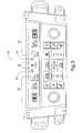
- the graphics 52,60 are shown on a heating, ventilation, and air conditioning (HVAC) control panel 50.
- HVAC heating, ventilation, and air conditioning
- the first plurality of light sources which are generally designated at reference signs 14 and14a, may be further defined as a first group of light sources at reference sign 14 and a second group of light sources at reference sign 14a.
- the first and second group of light sources 14, 14a within the first plurality of light sources emit light having a first color and wavelength.
- the second plurality of light sources 16 emit light having a second, different color and wavelength than the first plurality of light sources 14, 14a.
- the light sources 14, 14a, 16 may comprise any desirable source, such as for example, light emitting diodes (LEDs), incandescent lamps of different color, or the like.
- the LCD may include four plurality of light sources each respectively emitting light in four different colors.
- the LCD 10 is assembled in the following order.
- the light sources 14, 14a, 16 are arranged on the circuit board 12 in any desirable configuration.
- the first group of light sources 14 are arranged in a two-by-seven relationship and the second group of light sources 14a are arranged in a one-by-two relationship.
- the second plurality of light sources 16 are also arranged in a one-by-two relationship adjacent to the one-by-two relationship of the second group of light sources 14a.
- the first group of light sources 14 correspond to and illuminate a first plurality of graphics which are identified generally at reference signs 56, 58, and 60
- the second group of light sources 14a and the second plurality of light sources 16 correspond to and illuminate a second plurality of graphics, which are identified generally at reference signs 52 and 54.
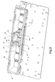
- the light box 18 Upon positioning the light sources 14, 14a, 16 on the circuit board 12, the light box 18 is attached to the circuit board 12 with fasteners (not shown) and snap clips. As seen more clearly in Figure 2, the light box 18 provides a perimeter of material encompassing the light sources 14, 14a, 16. When secured to the circuit board 12, any light propagated from the light sources 14, 14a, 16 is contained by an inner wall 28 of the light box 18 and directed toward the liquid crystal cell 26. Additionally, the light box 18 engages the circuit board 12 to prevent undesirable light leakage thereabout.
- the prism structure 20 Upon securing the light box 18 to the circuit board 12, the prism structure 20 is secured thereto; however, it will be appreciated the prism structure 20 may be secured to the light box 18 first, and then the light box 18 may be subsequently secured to the circuit board 12. As illustrated, the prism structure 20 includes a snap section 22 that engages the light box 18. As similarly described above with respect to the light box 18 and circuit board 12, the prism structure 20 engages the light box 18 at a shallow skirt 32 of opaque material to prevent undesirable light leakage of the second plurality of light sources 16 into the area of the light box 18 that is occupied by the first group of light sources 14. Upon securing the prism structure 20 to the light box 18 as described above, the sheet of plastic material 24 and liquid crystal cell 26 are positioned over and secured to the light box 18.
- the prism structure 20 relies on the optical property of right angle rectangular prisms with a sufficiently high index of refraction compared with its surrounding material such that light entering one face can only exit through the same face or the opposing face.
- the three sets of opposing faces therefore can be considered to be optically isolated from one another.
- the prism structure 20 includes a pair of substantially solid, rectangular prisms 30 located on each side of the snap section 22. Although only two prisms 30 are shown, it will be appreciated that any desirable number of prisms 30 may be incorporated into the design of the prism structure to function in the following manner.
- each rectangular prism 30 isolates one light source from the second plurality of light sources 16 and one light source from the second group of light sources 14a.
- one of the two light sources from the second group of light sources 14a is used to illuminate off-state segments of the second plurality of graphics 52, 54 in the first color while one of the light sources from the second plurality of light sources 16 is used to illuminate on-state segments of the second plurality of graphics 52, 54 in the second, different color.
- a shallow skirt of opaque material 32 integral with the light box 18 may encase a bottom face of the rectangular prism 30.
- the illustrated embodiment is directed to a rectangular prism 30, it will be appreciated that other shapes also can be used so long as some degree of optical isolation is maintained between the faces separating illumination of the graphic 52, 54 from the illumination in the general area surrounding the graphics 52, 54.
- the color segment (i.e. the "on” segments) of the second plurality of graphics 52, 54 of the liquid crystal cell 26 are not on, the general color light from the first plurality of light sources 14, 14a is turned on and illuminates the "off" color segments of the liquid crystal cell 26. Accordingly, the background color of the liquid crystal cell 26 is uniform since all of the illumination color is similar.
- the first group of light sources 14 are used to illuminate "on" segments of the first plurality of graphics 56, 58, 60 in the first color and the second plurality of light sources 16 are used to illuminate "on" segments of the second plurality of graphics 52, 54 in the second, different color.
- the prism 30 localizes and maintains the second, different color of the second plurality of graphics 52, 54 when segments from the first plurality of graphics 56, 58, 60 are illuminated by the first plurality of light sources 14 in the first color.
- the transition zone between the on-state graphic color and the off-state general background color can be quite small and depends on the distance from the top surface 34 of the rectangular prism 30 to the liquid crystal cell 26.
- the transition zone is not dark, as was found in conventional methods with separation walls, but rather, the zone consists of a boundary in which the colors may be somewhat mixed.
- the top surface 34 of the rectangular prism 30 is approximately same size or slightly larger than the area of the graphics 52, 54 to minimize color bleed in "off” areas. However, this bleed is only evident when the area of the graphics 52, 54 is/are in the on state. Accordingly, the portion of the liquid crystal cell with "on” segments diverts attention from the local "off" portions of the liquid crystal cell 26.
- the above-described LCD 10 may be illuminated with any desirable combination of colors for background lighting as well as color differentiation at the first plurality of graphics identified generally at 56, 58, 60 and the second plurality of graphics identified generally at 52, 54.
- the rear defrost graphic 52 and the front defrost graphic 54 may include an orange color while the remaining graphics 56, 58, 60 include a white color, when the color segments of the graphics are in the "on" state.
- the first plurality of light sources 14, 14a may include a stimulant color of a shorter wavelength, such as a blue and/or ultraviolet color, which may be down-converted to a color having a longer wavelength when the stimulant color passes through the color converting plastic material 24.
- the second plurality of light sources 16 may produce light having a longer wavelength than the stimulant color, which may pass through the color converting plastic material 24 without being converted to a substantially different color.
Landscapes
- Physics & Mathematics (AREA)
- Nonlinear Science (AREA)
- Mathematical Physics (AREA)
- Chemical & Material Sciences (AREA)
- Crystallography & Structural Chemistry (AREA)
- General Physics & Mathematics (AREA)
- Optics & Photonics (AREA)
- Devices For Indicating Variable Information By Combining Individual Elements (AREA)
- Liquid Crystal (AREA)
Abstract
Description
- The invention relates to liquid crystal displays. More particularly, the invention relates to a liquid crystal display with differently-colored localized display areas.
- Liquid crystal displays (LCDs) are transmissive in both the asserted and non-asserted display state and the ratio of the two states is the contrast ratio. For the purposes of discussion, assume the asserted state (i.e., an "on" segment or pixel) is more transmissive than the non-asserted state (i.e. an "off" segment or pixel). Because light leaks through "off" segments, the color of the light beneath the segment is often somewhat visible.
- Traditionally, when LCDs are designed to include a localized color section, one technique known in the art is to place a filter behind the off-color display area (i.e., a patch). Usually, the remaining area of the LCD is not filtered to maximize the utilization of the available light energy. Then, an illumination source, which contains wavelengths sufficient to produce respectively different colors associated with each of the localized sections, is used to illuminate the LCD. For this application, the off-color patch tends to have reduced light utilization because of the additional filter losses.
- Another traditional technique to localize color patches is to place a black (opaque) mask around the segments in the color patch. This is usually done when filters are used to produce the tone in the patch. While this method prevents the "off state" background color from being visible, the patch appears to be dark if the light source is turned off in the LCD "off state." If the light is left on when the segment is "off" the segment will leak light while its surrounding area will not. Because the eye is very sensitive to contrast, this application often appears as if the segment were either dimly lit (i.e., partly on) or fully lit, depending on other parameters.
- Other techniques for providing localized color sections may apply the use of a filter in each of the off-color patch area(s). This technique is described in
U.S. Patent No. 5,695,269 and assigned to the assignee of the present invention. However, when a filter is provided in each area of the LCD and if the lamps in both sections of the display are illuminated at the same time, the background color (i.e., "off" state) in both sections may tend to have different colors. - In some applications, a walled-off section may be provided below the color patch so the color patch is lit with one color while the rest of the display is lit with another color. Accordingly, light utilization is not reduced by using filters in one or both color areas. However, even with the application of a walled-off section, the "off areas" may still appear to have different colors. Even further, due to manufacturing tolerances, the walled-off section that separates the areas of different color usually cannot directly abut the LCD. As such, light from one color section may still leak into the other section, thereby shifting the apparent color of both sections in the vicinity of the boundary. This contamination of the color appearance is particularly troublesome with white displays because the eye is very sensitive to chromatic shifts in white tones. Another problem associated with walled-off sections is the thickness of the wall boundary itself. For example, when illumination sources are activated on each side of the wall, the wall thickness gives the appearance of a dark line in the "off area" of the LCD.
- As such, a need exists to improve the appearance of localized color sections in an LCD display.
- The present invention will now be described, by way of example, with reference to the accompanying drawings, in which:
- Figure 1 is an exploded view of a liquid crystal display according to an embodiment;
- Figure 2 is a partially assembled view of the liquid crystal display according to Figure 1; and
- Figure 3 is a top view of a heating, ventilation, and air conditioning (HVAC) control panel for the liquid crystal display according to Figure 1.
- The disadvantages described above are overcome and a number of advantages are realized by an inventive liquid crystal display (LCD), which is shown generally at 10 in Figure 1. The LCD 10 includes a
circuit board 12, a first plurality of light sources that are shown generally atreference signs light sources 16 located proximate the first plurality oflight sources light box 18, aprism structure 20, a sheet ofplastic material 24, such as a diffuser or a color converting plastic material, and aliquid crystal cell 26. In operation, the LCD 10 provides localized, differently-colored on-state segment illumination of control panel graphics 52-60 (Figure 3). According to the illustrated embodiment, thegraphics control panel 50. - The first plurality of light sources, which are generally designated at
reference signs 14 and14a, may be further defined as a first group of light sources atreference sign 14 and a second group of light sources atreference sign 14a. In general, the first and second group oflight sources light sources 16 emit light having a second, different color and wavelength than the first plurality oflight sources light sources light sources - Referring to Figures 1 and 2, the LCD 10 is assembled in the following order. First, the
light sources circuit board 12 in any desirable configuration. As illustrated, the first group oflight sources 14 are arranged in a two-by-seven relationship and the second group oflight sources 14a are arranged in a one-by-two relationship. The second plurality oflight sources 16 are also arranged in a one-by-two relationship adjacent to the one-by-two relationship of the second group oflight sources 14a. In reference to Figure 3, which illustrates the layout of the graphics 52-60 on theHVAC control panel 50, the first group oflight sources 14 correspond to and illuminate a first plurality of graphics which are identified generally atreference signs light sources 14a and the second plurality oflight sources 16 correspond to and illuminate a second plurality of graphics, which are identified generally atreference signs - Upon positioning the
light sources circuit board 12, thelight box 18 is attached to thecircuit board 12 with fasteners (not shown) and snap clips. As seen more clearly in Figure 2, thelight box 18 provides a perimeter of material encompassing thelight sources circuit board 12, any light propagated from thelight sources inner wall 28 of thelight box 18 and directed toward theliquid crystal cell 26. Additionally, thelight box 18 engages thecircuit board 12 to prevent undesirable light leakage thereabout. - Upon securing the
light box 18 to thecircuit board 12, theprism structure 20 is secured thereto; however, it will be appreciated theprism structure 20 may be secured to thelight box 18 first, and then thelight box 18 may be subsequently secured to thecircuit board 12. As illustrated, theprism structure 20 includes asnap section 22 that engages thelight box 18. As similarly described above with respect to thelight box 18 andcircuit board 12, theprism structure 20 engages thelight box 18 at ashallow skirt 32 of opaque material to prevent undesirable light leakage of the second plurality oflight sources 16 into the area of thelight box 18 that is occupied by the first group oflight sources 14. Upon securing theprism structure 20 to thelight box 18 as described above, the sheet ofplastic material 24 andliquid crystal cell 26 are positioned over and secured to thelight box 18. - Functionally, the
prism structure 20 relies on the optical property of right angle rectangular prisms with a sufficiently high index of refraction compared with its surrounding material such that light entering one face can only exit through the same face or the opposing face. The three sets of opposing faces therefore can be considered to be optically isolated from one another. As illustrated, theprism structure 20 includes a pair of substantially solid,rectangular prisms 30 located on each side of thesnap section 22. Although only twoprisms 30 are shown, it will be appreciated that any desirable number ofprisms 30 may be incorporated into the design of the prism structure to function in the following manner. - As illustrated, each
rectangular prism 30 isolates one light source from the second plurality oflight sources 16 and one light source from the second group oflight sources 14a. When isolated in this manner, one of the two light sources from the second group oflight sources 14a is used to illuminate off-state segments of the second plurality ofgraphics light sources 16 is used to illuminate on-state segments of the second plurality ofgraphics light sources 16 from leaking out into the general area of the first plurality oflight sources 14, a shallow skirt ofopaque material 32 integral with thelight box 18 may encase a bottom face of therectangular prism 30. Although the illustrated embodiment is directed to arectangular prism 30, it will be appreciated that other shapes also can be used so long as some degree of optical isolation is maintained between the faces separating illumination of the graphic 52, 54 from the illumination in the general area surrounding thegraphics - In operation, when the color segment (i.e. the "on" segments) of the second plurality of
graphics liquid crystal cell 26 are not on, the general color light from the first plurality oflight sources liquid crystal cell 26. Accordingly, the background color of theliquid crystal cell 26 is uniform since all of the illumination color is similar. Conversely, when the "on" color segments of the second plurality ofgraphics liquid crystal cell 26 are on, the first group oflight sources 14 are used to illuminate "on" segments of the first plurality ofgraphics light sources 16 are used to illuminate "on" segments of the second plurality ofgraphics - In relation to the second plurality of
graphics rectangular prisms 30, when the color segments are changed to the "on" state, the general color light from the first group oflight sources 14a under theprism 30 is turned off and the color light from one of the second plurality oflight sources 16 for the graphic 52, 54 is turned on. Accordingly, when the "on" segments of the second plurality ofgraphics light sources 16, theprism 30 localizes and maintains the second, different color of the second plurality ofgraphics graphics light sources 14 in the first color. - The transition zone between the on-state graphic color and the off-state general background color can be quite small and depends on the distance from the
top surface 34 of therectangular prism 30 to theliquid crystal cell 26. The transition zone is not dark, as was found in conventional methods with separation walls, but rather, the zone consists of a boundary in which the colors may be somewhat mixed. Preferably, thetop surface 34 of therectangular prism 30 is approximately same size or slightly larger than the area of thegraphics graphics liquid crystal cell 26. - The above-described LCD 10 may be illuminated with any desirable combination of colors for background lighting as well as color differentiation at the first plurality of graphics identified generally at 56, 58, 60 and the second plurality of graphics identified generally at 52, 54. According to the illustrated embodiment, the rear defrost graphic 52 and the front defrost graphic 54 may include an orange color while the remaining
graphics light sources plastic material 24. The second plurality oflight sources 16 may produce light having a longer wavelength than the stimulant color, which may pass through the color convertingplastic material 24 without being converted to a substantially different color. - While the invention has been specifically described in connection with certain specific embodiments thereof, it is to be understood that this is by way of illustration and not of limitation, and the scope of the appended claims should be construed as broadly as the prior art will permit.
Claims (11)
- A liquid crystal display (10) comprising:a first plurality of light sources including a first group of light sources (14) and a second group of light sources (14a), wherein the first group of light sources (14) illuminates segments of a first plurality of graphics (56, 58, 60) in a first color;a second plurality of light sources (16) that illuminates on segments of a second plurality of graphics (52, 54) in a second color; anda prism structure (20) located over the second plurality of light sources (16) and the second group of light sources (14a) to localize and maintain the illumination of the on segments of the second plurality of graphics (52, 54) in the second color when the first plurality of graphics (56, 58, 60) are illuminated in the first color by the first group of light sources (14).
- The liquid crystal display (10) according to Claim 1, wherein the second group of light sources (14a) illuminate the off segments of the second plurality of graphics (52, 54) in the first color when the second plurality of light sources (16) that illuminate the on segments of the second plurality of graphics (52, 54) in the second color are in the off state.
- The liquid crystal display (10) according to Claim 1 further comprising a light box (18) secured to a circuit board (12) providing a perimeter of material encompassing the first and second plurality of light sources (14, 14a, 16), wherein a liquid crystal cell (26) is operationally secured to the light box (18) and circuit board (12).
- The liquid crystal display (10) according to Claim 3 further comprising a sheet of color converting plastic material (24) placed between the light box (18) and the liquid crystal cell (26) to convert light propagating from the first plurality of light sources (14) and/or the second plurality of light sources (16) toward the liquid crystal cell.
- The liquid crystal display (10) according to Claim 3, wherein the prism structure (20) is secured to the light box (18) by a snap section (22).
- The liquid crystal display (10) according to Claim 5, wherein the prism structure (20) includes at least two substantially solid, rectangular prisms (30) located on each side of the snap section (22).
- The liquid crystal display (10) according to Claim 6, wherein each rectangular prism (30) is placed behind of the second plurality of graphics (52, 54).
- The liquid crystal display (10) according to Claim 1, wherein the first and second plurality of light sources (14, 14a, 16) are light emitting diodes.
- The liquid crystal display (10) according to Claim 4, wherein the first plurality of light sources (14, 14a) include a blue and/or ultraviolet light color having a shorter wavelength that is down-converted to a color of light of longer wavelengths when the blue or ultraviolet colored light passes through the color converting plastic material (24).
- The liquid crystal display (10) according to Claim 9 where the second plurality of light sources (16) produce light having a longer wavelength than the blue or ultraviolet colored light, wherein the light from the second plurality of light sources (16) passes through the color converting plastic (24) without being converted to a substantially different color.
- The liquid crystal display (10) according to Claim 1 wherein the first and second plurality of light sources (14, 14a, 16) are incandescent lamps of different colors.
Applications Claiming Priority (1)
| Application Number | Priority Date | Filing Date | Title |
|---|---|---|---|
| US11/196,701 US20070030413A1 (en) | 2005-08-03 | 2005-08-03 | Liquid crystal display with differently-colored localized display areas |
Publications (2)
| Publication Number | Publication Date |
|---|---|
| EP1750169A2 true EP1750169A2 (en) | 2007-02-07 |
| EP1750169A3 EP1750169A3 (en) | 2007-03-14 |
Family
ID=36888947
Family Applications (1)
| Application Number | Title | Priority Date | Filing Date |
|---|---|---|---|
| EP06076337A Withdrawn EP1750169A3 (en) | 2005-08-03 | 2006-06-30 | Liquid crystal display with differently-colored localized display areas |
Country Status (2)
| Country | Link |
|---|---|
| US (1) | US20070030413A1 (en) |
| EP (1) | EP1750169A3 (en) |
Families Citing this family (2)
| Publication number | Priority date | Publication date | Assignee | Title |
|---|---|---|---|---|
| KR20140046679A (en) * | 2012-10-10 | 2014-04-21 | 엘지전자 주식회사 | A display apparatus for air conditioner and controlling method of the same |
| CN104216169B (en) * | 2013-05-30 | 2017-09-05 | 群创光电股份有限公司 | display device |
Citations (1)
| Publication number | Priority date | Publication date | Assignee | Title |
|---|---|---|---|---|
| US5695269A (en) | 1996-01-29 | 1997-12-09 | Delco Electronics Corporation | Multi-color display lighting by led |
Family Cites Families (12)
| Publication number | Priority date | Publication date | Assignee | Title |
|---|---|---|---|---|
| GB2094051A (en) * | 1981-02-28 | 1982-09-08 | Thorn Emi Ltd | Display device |
| CA1258312A (en) * | 1985-04-12 | 1989-08-08 | Kozo Katogi | Liquid crystal color display apparatus |
| US5339178A (en) * | 1993-03-19 | 1994-08-16 | Motorola, Inc. | LCD assembly with light pipe having lightguides extending from surface to surface and retaining means integral with the lightpipe |
| US5428468A (en) * | 1993-11-05 | 1995-06-27 | Alliedsignal Inc. | Illumination system employing an array of microprisms |
| US5785404A (en) * | 1995-06-29 | 1998-07-28 | Siemens Microelectronics, Inc. | Localized illumination device |
| DE19702957C2 (en) * | 1997-01-28 | 1999-01-28 | Hella Kg Hueck & Co | Display device, in particular for the actuation unit of a motor vehicle component such as an air conditioning system |
| US6795137B1 (en) * | 1999-04-26 | 2004-09-21 | Microsoft Corporation | Methods and apparatus for implementing transmissive display devices |
| JP2001035652A (en) * | 1999-07-21 | 2001-02-09 | Matsushita Electric Ind Co Ltd | ELECTROLUMINESCENT ELEMENT AND LIGHTING UNIT USING SAME |
| JP2002042535A (en) * | 2000-07-05 | 2002-02-08 | Internatl Business Mach Corp <Ibm> | Display device and surface light source device |
| US7052152B2 (en) * | 2003-10-03 | 2006-05-30 | Philips Lumileds Lighting Company, Llc | LCD backlight using two-dimensional array LEDs |
| US20050280894A1 (en) * | 2004-04-02 | 2005-12-22 | David Hartkop | Apparatus for creating a scanning-column backlight in a scanning aperture display device |
| US7350934B2 (en) * | 2005-05-03 | 2008-04-01 | Delphi Technologies, Inc. | Illuminated display system |
-
2005
- 2005-08-03 US US11/196,701 patent/US20070030413A1/en not_active Abandoned
-
2006
- 2006-06-30 EP EP06076337A patent/EP1750169A3/en not_active Withdrawn
Patent Citations (1)
| Publication number | Priority date | Publication date | Assignee | Title |
|---|---|---|---|---|
| US5695269A (en) | 1996-01-29 | 1997-12-09 | Delco Electronics Corporation | Multi-color display lighting by led |
Also Published As
| Publication number | Publication date |
|---|---|
| US20070030413A1 (en) | 2007-02-08 |
| EP1750169A3 (en) | 2007-03-14 |
Similar Documents
| Publication | Publication Date | Title |
|---|---|---|
| US7630028B2 (en) | Color liquid crystal display having a blue light source and fluorescent wavelength conversion areas | |
| JP2889949B2 (en) | LCD lighting system | |
| US20030012035A1 (en) | Programmable multi-color backlight for a liquid crystal display | |
| US8354992B2 (en) | Appearance improvement for zone backlit LCD displays | |
| US7152988B2 (en) | Direct point-light type backlight module and liquid crystal display using the same | |
| US20070274093A1 (en) | LED backlight system for LCD displays | |
| US7762703B2 (en) | Heads-up display, motor vehicle and method of operating a heads-up display | |
| CN208141087U (en) | A kind of display device | |
| JPH09146089A (en) | Surface light source for color display device and liquid crystal display device | |
| EP1319553A1 (en) | Vehicle instrument | |
| CN111103723A (en) | A liquid crystal display backlight module | |
| KR100739797B1 (en) | Display device using external light | |
| RU2361285C2 (en) | Display for forming colour images and text, recognisable in incident light | |
| CN201439906U (en) | Edge-lighting backlight module and liquid crystal display (LCD) | |
| US12117702B2 (en) | Backlight unit for a vehicle component | |
| US8876326B1 (en) | Multi-mode LED edge-light for NVIS compatible operation | |
| CN101501558B (en) | Liquid crystal display device | |
| US7014347B2 (en) | Illumination device for a color liquid crystal display | |
| US7959340B2 (en) | Device for backlighting a liquid-crystal display facility for a display and/or control unit, in particular in a household appliance | |
| US20070030413A1 (en) | Liquid crystal display with differently-colored localized display areas | |
| US8232492B1 (en) | Electronically balanced illuminated panel | |
| US20090180052A1 (en) | Liquid crystal display device and back light unit thereof | |
| JPS61285429A (en) | Liquid crystal flat panel display | |
| KR200195635Y1 (en) | Multi display signboard | |
| JP2003057629A (en) | Display panel device |
Legal Events
| Date | Code | Title | Description |
|---|---|---|---|
| PUAI | Public reference made under article 153(3) epc to a published international application that has entered the european phase |
Free format text: ORIGINAL CODE: 0009012 |
|
| AK | Designated contracting states |
Kind code of ref document: A2 Designated state(s): AT BE BG CH CY CZ DE DK EE ES FI FR GB GR HU IE IS IT LI LT LU LV MC NL PL PT RO SE SI SK TR |
|
| AX | Request for extension of the european patent |
Extension state: AL BA HR MK YU |
|
| PUAL | Search report despatched |
Free format text: ORIGINAL CODE: 0009013 |
|
| AK | Designated contracting states |
Kind code of ref document: A3 Designated state(s): AT BE BG CH CY CZ DE DK EE ES FI FR GB GR HU IE IS IT LI LT LU LV MC NL PL PT RO SE SI SK TR |
|
| AX | Request for extension of the european patent |
Extension state: AL BA HR MK YU |
|
| 17P | Request for examination filed |
Effective date: 20070914 |
|
| 17Q | First examination report despatched |
Effective date: 20071022 |
|
| AKX | Designation fees paid |
Designated state(s): AT BE BG CH CY CZ DE DK EE ES FI FR GB GR HU IE IS IT LI LT LU LV MC NL PL PT RO SE SI SK TR |
|
| STAA | Information on the status of an ep patent application or granted ep patent |
Free format text: STATUS: THE APPLICATION IS DEEMED TO BE WITHDRAWN |
|
| 18D | Application deemed to be withdrawn |
Effective date: 20080503 |