EP1749985A1 - Exhaust gas purifier - Google Patents
Exhaust gas purifier Download PDFInfo
- Publication number
- EP1749985A1 EP1749985A1 EP04745287A EP04745287A EP1749985A1 EP 1749985 A1 EP1749985 A1 EP 1749985A1 EP 04745287 A EP04745287 A EP 04745287A EP 04745287 A EP04745287 A EP 04745287A EP 1749985 A1 EP1749985 A1 EP 1749985A1
- Authority
- EP
- European Patent Office
- Prior art keywords
- particulate filter
- temperature sensor
- exhaust gas
- exhaust
- sensing element
- Prior art date
- Legal status (The legal status is an assumption and is not a legal conclusion. Google has not performed a legal analysis and makes no representation as to the accuracy of the status listed.)
- Granted
Links
Images




Classifications
-
- F—MECHANICAL ENGINEERING; LIGHTING; HEATING; WEAPONS; BLASTING
- F01—MACHINES OR ENGINES IN GENERAL; ENGINE PLANTS IN GENERAL; STEAM ENGINES
- F01N—GAS-FLOW SILENCERS OR EXHAUST APPARATUS FOR MACHINES OR ENGINES IN GENERAL; GAS-FLOW SILENCERS OR EXHAUST APPARATUS FOR INTERNAL-COMBUSTION ENGINES
- F01N3/00—Exhaust or silencing apparatus having means for purifying, rendering innocuous, or otherwise treating exhaust
- F01N3/02—Exhaust or silencing apparatus having means for purifying, rendering innocuous, or otherwise treating exhaust for cooling, or for removing solid constituents of, exhaust
- F01N3/021—Exhaust or silencing apparatus having means for purifying, rendering innocuous, or otherwise treating exhaust for cooling, or for removing solid constituents of, exhaust by means of filters
- F01N3/033—Exhaust or silencing apparatus having means for purifying, rendering innocuous, or otherwise treating exhaust for cooling, or for removing solid constituents of, exhaust by means of filters in combination with other devices
- F01N3/0335—Exhaust or silencing apparatus having means for purifying, rendering innocuous, or otherwise treating exhaust for cooling, or for removing solid constituents of, exhaust by means of filters in combination with other devices with exhaust silencers in a single housing
-
- B—PERFORMING OPERATIONS; TRANSPORTING
- B01—PHYSICAL OR CHEMICAL PROCESSES OR APPARATUS IN GENERAL
- B01D—SEPARATION
- B01D46/00—Filters or filtering processes specially modified for separating dispersed particles from gases or vapours
- B01D46/24—Particle separators, e.g. dust precipitators, using rigid hollow filter bodies
- B01D46/2403—Particle separators, e.g. dust precipitators, using rigid hollow filter bodies characterised by the physical shape or structure of the filtering element
- B01D46/2418—Honeycomb filters
-
- B—PERFORMING OPERATIONS; TRANSPORTING
- B01—PHYSICAL OR CHEMICAL PROCESSES OR APPARATUS IN GENERAL
- B01D—SEPARATION
- B01D46/00—Filters or filtering processes specially modified for separating dispersed particles from gases or vapours
- B01D46/42—Auxiliary equipment or operation thereof
- B01D46/44—Auxiliary equipment or operation thereof controlling filtration
- B01D46/448—Auxiliary equipment or operation thereof controlling filtration by temperature measuring
-
- B—PERFORMING OPERATIONS; TRANSPORTING
- B01—PHYSICAL OR CHEMICAL PROCESSES OR APPARATUS IN GENERAL
- B01D—SEPARATION
- B01D46/00—Filters or filtering processes specially modified for separating dispersed particles from gases or vapours
- B01D46/66—Regeneration of the filtering material or filter elements inside the filter
- B01D46/80—Chemical processes for the removal of the retained particles, e.g. by burning
- B01D46/82—Chemical processes for the removal of the retained particles, e.g. by burning with catalysts
-
- B—PERFORMING OPERATIONS; TRANSPORTING
- B01—PHYSICAL OR CHEMICAL PROCESSES OR APPARATUS IN GENERAL
- B01D—SEPARATION
- B01D53/00—Separation of gases or vapours; Recovering vapours of volatile solvents from gases; Chemical or biological purification of waste gases, e.g. engine exhaust gases, smoke, fumes, flue gases, aerosols
- B01D53/34—Chemical or biological purification of waste gases
- B01D53/92—Chemical or biological purification of waste gases of engine exhaust gases
- B01D53/94—Chemical or biological purification of waste gases of engine exhaust gases by catalytic processes
-
- F—MECHANICAL ENGINEERING; LIGHTING; HEATING; WEAPONS; BLASTING
- F01—MACHINES OR ENGINES IN GENERAL; ENGINE PLANTS IN GENERAL; STEAM ENGINES
- F01N—GAS-FLOW SILENCERS OR EXHAUST APPARATUS FOR MACHINES OR ENGINES IN GENERAL; GAS-FLOW SILENCERS OR EXHAUST APPARATUS FOR INTERNAL-COMBUSTION ENGINES
- F01N13/00—Exhaust or silencing apparatus characterised by constructional features
- F01N13/008—Mounting or arrangement of exhaust sensors in or on exhaust apparatus
-
- F—MECHANICAL ENGINEERING; LIGHTING; HEATING; WEAPONS; BLASTING
- F01—MACHINES OR ENGINES IN GENERAL; ENGINE PLANTS IN GENERAL; STEAM ENGINES
- F01N—GAS-FLOW SILENCERS OR EXHAUST APPARATUS FOR MACHINES OR ENGINES IN GENERAL; GAS-FLOW SILENCERS OR EXHAUST APPARATUS FOR INTERNAL-COMBUSTION ENGINES
- F01N13/00—Exhaust or silencing apparatus characterised by constructional features
- F01N13/009—Exhaust or silencing apparatus characterised by constructional features having two or more separate purifying devices arranged in series
- F01N13/0097—Exhaust or silencing apparatus characterised by constructional features having two or more separate purifying devices arranged in series the purifying devices are arranged in a single housing
-
- F—MECHANICAL ENGINEERING; LIGHTING; HEATING; WEAPONS; BLASTING
- F01—MACHINES OR ENGINES IN GENERAL; ENGINE PLANTS IN GENERAL; STEAM ENGINES
- F01N—GAS-FLOW SILENCERS OR EXHAUST APPARATUS FOR MACHINES OR ENGINES IN GENERAL; GAS-FLOW SILENCERS OR EXHAUST APPARATUS FOR INTERNAL-COMBUSTION ENGINES
- F01N3/00—Exhaust or silencing apparatus having means for purifying, rendering innocuous, or otherwise treating exhaust
- F01N3/02—Exhaust or silencing apparatus having means for purifying, rendering innocuous, or otherwise treating exhaust for cooling, or for removing solid constituents of, exhaust
- F01N3/021—Exhaust or silencing apparatus having means for purifying, rendering innocuous, or otherwise treating exhaust for cooling, or for removing solid constituents of, exhaust by means of filters
-
- F—MECHANICAL ENGINEERING; LIGHTING; HEATING; WEAPONS; BLASTING
- F01—MACHINES OR ENGINES IN GENERAL; ENGINE PLANTS IN GENERAL; STEAM ENGINES
- F01N—GAS-FLOW SILENCERS OR EXHAUST APPARATUS FOR MACHINES OR ENGINES IN GENERAL; GAS-FLOW SILENCERS OR EXHAUST APPARATUS FOR INTERNAL-COMBUSTION ENGINES
- F01N3/00—Exhaust or silencing apparatus having means for purifying, rendering innocuous, or otherwise treating exhaust
- F01N3/02—Exhaust or silencing apparatus having means for purifying, rendering innocuous, or otherwise treating exhaust for cooling, or for removing solid constituents of, exhaust
- F01N3/021—Exhaust or silencing apparatus having means for purifying, rendering innocuous, or otherwise treating exhaust for cooling, or for removing solid constituents of, exhaust by means of filters
- F01N3/033—Exhaust or silencing apparatus having means for purifying, rendering innocuous, or otherwise treating exhaust for cooling, or for removing solid constituents of, exhaust by means of filters in combination with other devices
- F01N3/035—Exhaust or silencing apparatus having means for purifying, rendering innocuous, or otherwise treating exhaust for cooling, or for removing solid constituents of, exhaust by means of filters in combination with other devices with catalytic reactors
-
- F—MECHANICAL ENGINEERING; LIGHTING; HEATING; WEAPONS; BLASTING
- F01—MACHINES OR ENGINES IN GENERAL; ENGINE PLANTS IN GENERAL; STEAM ENGINES
- F01N—GAS-FLOW SILENCERS OR EXHAUST APPARATUS FOR MACHINES OR ENGINES IN GENERAL; GAS-FLOW SILENCERS OR EXHAUST APPARATUS FOR INTERNAL-COMBUSTION ENGINES
- F01N2560/00—Exhaust systems with means for detecting or measuring exhaust gas components or characteristics
- F01N2560/06—Exhaust systems with means for detecting or measuring exhaust gas components or characteristics the means being a temperature sensor
Definitions
- the present invention relates to an exhaust emission control device.
- Particulates or particulate matter from a diesel engine is mainly constituted by carbonic soot and a soluble organic fraction (SOF) of high-boiling hydrocarbon and contains a trace of sulfate (misty sulfuric acid fraction).
- SOF soluble organic fraction
- a particulate filter 6 is incorporated in an exhaust pipe 4 through which exhaust gas 3 from a diesel engine 1 flows.
- the muffler 5 has inlet and outlet pipes 8 and 9 between which is secured a required size of reception chamber 12 defined by and between dispersion plates 10 and 11 and with a number of communicating holes 10a and 11a, respectively.
- the particulate filter 6 is in the reception chamber 12.
- the particulate filter 6 is constituted by a porous honeycomb structure made of ceramics and having lattice-like compartmentalized passages 6a; alternate ones of the passages 6a have plugged inlets and the remaining passages 6a with unplugged open inlets are plugged at their outlets.
- the exhaust gas 3 passing through thin porous walls 6b compartmentalizing the respective passages 6a is discharged downstream.
- the particulates which are captured by and accumulated on inner surfaces of the walls 6b, require to be appropriately burned off so as to regenerate the particulate filter 6 before exhaust resistance increases considerably due to clogging.
- the exhaust gas from the diesel engine in a normal operating status rarely has a chance to reach a temperature level at which the particulates spontaneously ignite.
- catalytic regenerative particulate filter 6 integrally carrying oxidation catalyst has been developed for practical use, said oxidation catalyst being for example platinum-alumina catalyst added with an appropriate amount of rare-earth element such as cerium.
- Adoption of such catalytic regenerative particulate filter 6 accelerates oxidation reaction of the captured particulates to lower their ignition temperature, so that the particulates can be burned off at an exhaust temperature lower than ever before.
- addition of the fuel upstream of the particulate filter 6 causes the added fuel to effect oxidation reaction on the oxidation catalyst of the filter 6; reaction heat generated therefrom increases the catalyst floor temperature to burn off the particulates, thereby regenerating the particulate filter 6.
- Fig. 4 which includes a flow-through type oxidation catalyst 13 (see Fig. 5) upstream of the particulate filter 6 in the reception chamber 12 so as to especially accelerate the oxidation reaction of the captured particulates
- the added fuel is oxidized at the oxidation catalyst 13 upstream of the particulate filter 6 to generate reaction heat; the exhaust gas 3 elevated in temperature by the reaction heat is introduced into the particulate filter 6.
- forcible regeneration of the particulate filter 6 can be accomplished even at further lower exhaust temperature.
- a temperature sensor is attached to the filter casing 7 to detect inner temperature of the reception chamber 12, and regeneration control is conducted on the basis of temperature detected by the temperature sensor.
- a temperature sensor is attached to the filter casing 7 to detect inner temperature of the reception chamber 12, and regeneration control is conducted on the basis of temperature detected by the temperature sensor.
- consideration has been taken only to the facts that interference with surrounding structures is averted and that a minimum height above ground (clearance between roadbed and a lowermost part of chassis mechanism: load clearance) is ensured; actually, no specific consideration has been taken as to position of a sensing element of the temperature sensor within the filter casing 7.
- a sensing element 15 of the temperature sensor 14 inserted into the reception chamber 12 near the inlet-side dispersion plate 10 happens to get behind a wall portion between the communicating holes 10a on the dispersion plate 10
- the sensing element 15 of the sensor 14 is not exposed to any flow of the exhaust gas 3, which may cause lowering of accuracy in temperature sensing especially at a lower flow rate of the exhaust gas 3, failing to accurately conduct the regeneration control of the particulate filter 6.
- the invention was made in view of the above and has its object to enhance sensing accuracy of a temperature sensor so as to accurately conduct regeneration control of a particulate filter.
- the invention is directed to an exhaust emission control device wherein a pair of dispersion plates with a number of communicating holes are arranged in a filter casing incorporated in an exhaust pipe such that the plates are opposed to each other in a direction of flows of exhaust gas, a catalytic regenerative particulate filter being received in a reception chamber defined by and between the dispersion plates, characterized in that a temperature sensor is fitted to the filter casing so as to detect exhaust temperature in the reception chamber, a sensing element of the temperature sensor being adapted to be in a flow of the exhaust gas.
- the sensing element of the temperature sensor is always exposed to the exhaust gas flow, so that sensing accuracy of the temperature sensor is enhanced to thereby attain accurate regeneration control of the particulate filter.
- the sensing element of the temperature sensor may be arranged just behind one of the communication holes of the inlet-side dispersion plate and/or just before one of the communicating holes of the outlet-side dispersion plate; alternatively or further, in a case where oxidation catalyst is arranged upstream of the particulate filter within the reception chamber, the sensing member of the temperature sensor may be arranged in a flow of the exhaust gas between the oxidation catalyst and the particulate filter.
- the sensing element of the temperature sensor can be always exposed to a flow of the exhaust gas, which advantageously results in excellent effect that sensing accuracy of the temperature sensor can be substantially enhanced in comparison with the prior art and thus the regeneration control of the particulate filter can be accurately conducted.
- Figs. 7 and 8 show an embodiment of the invention in which parts similar to those in Figs. 1-6 are designated by the same reference numerals.
- a pair of dispersion plates 10 and 11 with a number of communicating holes 10a and 11a, respectively, are arranged in a filter casing 7 incorporated in an exhaust pipe 4 such that the dispersion plates are opposed to each other in a direction of flows of the exhaust gas 3, catalytic regenerative particulate filter 6 being received in a reception chamber 12 defined by and between the dispersion plates 10 and 11, oxidation catalyst 13 being arranged in the reception chamber 12 and upstream of the particulate filter 6.
- a sensing element of the temperature sensor 14 is arranged in each of a position within the reception chamber 12 and adjacent to the inlet-side dispersion plate 10, a position within the reception chamber 12 and adjacent to the outlet-side dispersion plate 11 and a position between the oxidation catalyst 13 and the particulate filter 6.
- the temperature sensor 14 in the reception chamber 12 adjacent to the inlet-side dispersion plate 10 has the sensing element 15 arranged just behind one of the communicating holes 10a of the dispersion plate 10.
- the temperature sensor 14 in the reception chamber 12 adjacent to the outlet-side dispersion plate 11 has the sensing element 15 arranged just in front of one of the communicating holes 11a of the dispersion plate 11.
- the sensing elements 15 of the temperature sensors 14 are arranged to correspond with the relatively larger-diameter communicating holes 10a and 11a surrounding connections to the inlet and exit pipes 8 and 9, respectively; alternatively, they may be arranged to correspond with the relatively smaller-diameter communicating holes 10a and 11a surrounding the connections to the inlet and exit pipes 8 and 9, respectively.
- the temperature sensor 14 between the oxidation catalyst 13 and the particulate filter 6 has the sensing element 15 arranged in one of flows of the exhaust gas from the passages of the oxidation catalyst 13 to the passages 6a of the particulate filter 6.
- the exhaust gas flowing via a specific one of the communicating holes 10a of the inlet-side dispersion plate 10 into the reception chamber 12 always tends to form flow of the exhaust gas directed to a specific one of the communicating holes 11a on the outlet-side dispersion plate 11, so that predetermined flows of the exhaust gas 3 are formed between the oxidation catalyst 13 and the particulate filter 6, the sensing element 15 of the temperature sensor 14 being arranged in one of such flows of the exhaust gas.
- the sensing elements 15 of the temperature sensors 14 are always exposed to flows of the exhaust gas 3, whereby sensing accuracy of the temperature sensors 14 are substantially enhanced in comparison with the prior art and thus regeneration control of the particulate filter 6 can be accurately conducted.
- Fig. 9 shows a further embodiment applied to the dispersion plates of a type different from that shown in Fig. 8.
- the dispersion plates 10 and 11 shown have the inlet and exit pipes 8 and 9 arranged eccentrically due to layout relationship of the muffler 5 with surrounding structures, a number of relatively smaller-diameter communicating holes 10a and 11a being dispersed around connections to the pipes.
- the temperature sensor 14 positioned in the reception chamber 12 and adjacent to the inlet-side dispersion plate 10 has the sensing element arranged just behind a relatively larger-diameter communicating hole 10a among the communicating holes 10a on the dispersion plate 10; similarly, the temperature sensor 14 in the reception chamber 12 adjacent to the outlet-side dispersion plate 11 has the sensing element 15 just in front of a relatively larger-diameter communicating hole 11a among the communicating holes 11a on the dispersion plate 11.
- Such embodiment applied to this kind of dispersion plates 10 and 11 can have effects and advantages similar to those in the above-mentioned embodiment.
- an exhaust emission control device of the invention is not limited to the above-mentioned embodiments and that various changes and modifications may be made without leaving the gist of the invention.
- the communicating holes on the outlet-side dispersion plate may be provided with inner pipes for enhancing the silencing effect.
Landscapes
- Engineering & Computer Science (AREA)
- Chemical & Material Sciences (AREA)
- Combustion & Propulsion (AREA)
- Chemical Kinetics & Catalysis (AREA)
- General Engineering & Computer Science (AREA)
- Mechanical Engineering (AREA)
- Analytical Chemistry (AREA)
- Health & Medical Sciences (AREA)
- General Chemical & Material Sciences (AREA)
- Oil, Petroleum & Natural Gas (AREA)
- Physics & Mathematics (AREA)
- Geometry (AREA)
- Environmental & Geological Engineering (AREA)
- Biomedical Technology (AREA)
- Exhaust Gas After Treatment (AREA)
- Processes For Solid Components From Exhaust (AREA)
Abstract
Description
- The present invention relates to an exhaust emission control device.
- Particulates or particulate matter from a diesel engine is mainly constituted by carbonic soot and a soluble organic fraction (SOF) of high-boiling hydrocarbon and contains a trace of sulfate (misty sulfuric acid fraction). In order to suppress suck kind of particulates from being discharged to atmosphere, it has been carried out as shown in Fig. 1 that a
particulate filter 6 is incorporated in anexhaust pipe 4 through whichexhaust gas 3 from adiesel engine 1 flows. - In the example shown,
exhaust gas 3 discharged from an automobile's diesel engine 1 (internal combustion engine) via anexhaust manifold 2 flows through anexhaust pipe 4 with amuffler 5 which receives therein catalyticregenerative particulate filter 6 integrally carrying oxidation catalyst, theparticulate filter 6 being encased by afilter casing 7 which forms an outer cylinder of themuffler 5. - More specifically, as shown in enlarged scale in Fig. 2, the
muffler 5 has inlet andoutlet pipes reception chamber 12 defined by and betweendispersion plates holes particulate filter 6 is in thereception chamber 12. - As schematically shown in section in Fig. 3, the
particulate filter 6 is constituted by a porous honeycomb structure made of ceramics and having lattice-like compartmentalized passages 6a; alternate ones of the passages 6a have plugged inlets and the remaining passages 6a with unplugged open inlets are plugged at their outlets. Thus, only theexhaust gas 3 passing through thin porous walls 6b compartmentalizing the respective passages 6a is discharged downstream. - The particulates, which are captured by and accumulated on inner surfaces of the walls 6b, require to be appropriately burned off so as to regenerate the
particulate filter 6 before exhaust resistance increases considerably due to clogging. However, the exhaust gas from the diesel engine in a normal operating status rarely has a chance to reach a temperature level at which the particulates spontaneously ignite. Thus, catalytic regenerativeparticulate filter 6 integrally carrying oxidation catalyst has been developed for practical use, said oxidation catalyst being for example platinum-alumina catalyst added with an appropriate amount of rare-earth element such as cerium. - Adoption of such catalytic
regenerative particulate filter 6 accelerates oxidation reaction of the captured particulates to lower their ignition temperature, so that the particulates can be burned off at an exhaust temperature lower than ever before. - However, even if such catalytic
regenerative particulate filter 6 is adopted, an accumulated particulate amount may exceed a treated particulate amount in an operation region with lower exhaust temperature. When such operation status with lower exhaust temperature continues, there may be a fear that regeneration of theparticulate filter 6 does not proceed well, disadvantageously resulting in excessive capturing of particulates by theparticulate filter 6. In order to overcome this, it has been considered that, when the accumulated particulate amount becomes increased, fuel is added to theexhaust gas 3 upstream of theparticulate filter 6 so as to forcibly regenerate thefilter 6. - More specifically, addition of the fuel upstream of the
particulate filter 6 causes the added fuel to effect oxidation reaction on the oxidation catalyst of thefilter 6; reaction heat generated therefrom increases the catalyst floor temperature to burn off the particulates, thereby regenerating theparticulate filter 6. - This kind of forcible regeneration of the
particulate filter 6 is disclosed, for example, in the followingReferences - [Reference 1]
JP2003-155915A - [Reference 2]
JP2003-222040A - In an exhaust emission control device as shown in Fig. 4 which includes a flow-through type oxidation catalyst 13 (see Fig. 5) upstream of the
particulate filter 6 in thereception chamber 12 so as to especially accelerate the oxidation reaction of the captured particulates, the added fuel is oxidized at theoxidation catalyst 13 upstream of theparticulate filter 6 to generate reaction heat; theexhaust gas 3 elevated in temperature by the reaction heat is introduced into theparticulate filter 6. Thus, forcible regeneration of theparticulate filter 6 can be accomplished even at further lower exhaust temperature. - For forcible regeneration of the
particulate filter 6 through this kind of fuel addition, a temperature sensor is attached to thefilter casing 7 to detect inner temperature of thereception chamber 12, and regeneration control is conducted on the basis of temperature detected by the temperature sensor. However, upon attachment of such temperature sensor on thefilter casing 7 incorporated in theexhaust pipe 4, conventionally, consideration has been taken only to the facts that interference with surrounding structures is averted and that a minimum height above ground (clearance between roadbed and a lowermost part of chassis mechanism: load clearance) is ensured; actually, no specific consideration has been taken as to position of a sensing element of the temperature sensor within thefilter casing 7. - Thus, for example as shown in Fig. 6, if a
sensing element 15 of thetemperature sensor 14 inserted into thereception chamber 12 near the inlet-side dispersion plate 10 happens to get behind a wall portion between the communicatingholes 10a on thedispersion plate 10, thesensing element 15 of thesensor 14 is not exposed to any flow of theexhaust gas 3, which may cause lowering of accuracy in temperature sensing especially at a lower flow rate of theexhaust gas 3, failing to accurately conduct the regeneration control of theparticulate filter 6. - The invention was made in view of the above and has its object to enhance sensing accuracy of a temperature sensor so as to accurately conduct regeneration control of a particulate filter.
- The invention is directed to an exhaust emission control device wherein a pair of dispersion plates with a number of communicating holes are arranged in a filter casing incorporated in an exhaust pipe such that the plates are opposed to each other in a direction of flows of exhaust gas, a catalytic regenerative particulate filter being received in a reception chamber defined by and between the dispersion plates, characterized in that a temperature sensor is fitted to the filter casing so as to detect exhaust temperature in the reception chamber, a sensing element of the temperature sensor being adapted to be in a flow of the exhaust gas.
- Thus, the sensing element of the temperature sensor is always exposed to the exhaust gas flow, so that sensing accuracy of the temperature sensor is enhanced to thereby attain accurate regeneration control of the particulate filter.
- In specifically embodying the inventive exhaust emission control device, the sensing element of the temperature sensor may be arranged just behind one of the communication holes of the inlet-side dispersion plate and/or just before one of the communicating holes of the outlet-side dispersion plate; alternatively or further, in a case where oxidation catalyst is arranged upstream of the particulate filter within the reception chamber, the sensing member of the temperature sensor may be arranged in a flow of the exhaust gas between the oxidation catalyst and the particulate filter.
- According to an exhaust emission control device of the invention, the sensing element of the temperature sensor can be always exposed to a flow of the exhaust gas, which advantageously results in excellent effect that sensing accuracy of the temperature sensor can be substantially enhanced in comparison with the prior art and thus the regeneration control of the particulate filter can be accurately conducted.
- Embodiments of the invention will be described in conjunction with the drawings.
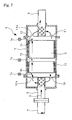
- Figs. 7 and 8 show an embodiment of the invention in which parts similar to those in Figs. 1-6 are designated by the same reference numerals.
- As shown in Fig. 7, in the embodiment, a pair of
dispersion plates holes filter casing 7 incorporated in anexhaust pipe 4 such that the dispersion plates are opposed to each other in a direction of flows of theexhaust gas 3, catalytic regenerativeparticulate filter 6 being received in areception chamber 12 defined by and between thedispersion plates oxidation catalyst 13 being arranged in thereception chamber 12 and upstream of theparticulate filter 6. A sensing element of thetemperature sensor 14 is arranged in each of a position within thereception chamber 12 and adjacent to the inlet-side dispersion plate 10, a position within thereception chamber 12 and adjacent to the outlet-side dispersion plate 11 and a position between theoxidation catalyst 13 and theparticulate filter 6. - More specifically, as shown in enlarged scale in Fig. 8, the
temperature sensor 14 in thereception chamber 12 adjacent to the inlet-side dispersion plate 10 has thesensing element 15 arranged just behind one of the communicatingholes 10a of thedispersion plate 10. Similarly, thetemperature sensor 14 in thereception chamber 12 adjacent to the outlet-side dispersion plate 11 has thesensing element 15 arranged just in front of one of the communicatingholes 11a of thedispersion plate 11. - In Fig. 8, the
sensing elements 15 of thetemperature sensors 14 are arranged to correspond with the relatively larger-diameter communicating holes exit pipes diameter communicating holes exit pipes - The
temperature sensor 14 between theoxidation catalyst 13 and theparticulate filter 6 has thesensing element 15 arranged in one of flows of the exhaust gas from the passages of theoxidation catalyst 13 to the passages 6a of theparticulate filter 6. - Further specifically, according to the inventors' knowledge obtained from various kinds of experiments, the exhaust gas flowing via a specific one of the communicating
holes 10a of the inlet-side dispersion plate 10 into thereception chamber 12 always tends to form flow of the exhaust gas directed to a specific one of the communicatingholes 11a on the outlet-side dispersion plate 11, so that predetermined flows of theexhaust gas 3 are formed between theoxidation catalyst 13 and theparticulate filter 6, thesensing element 15 of thetemperature sensor 14 being arranged in one of such flows of the exhaust gas. - With the thus constructed exhaust emission control device, the
sensing elements 15 of thetemperature sensors 14 are always exposed to flows of theexhaust gas 3, whereby sensing accuracy of thetemperature sensors 14 are substantially enhanced in comparison with the prior art and thus regeneration control of theparticulate filter 6 can be accurately conducted. - Fig. 9 shows a further embodiment applied to the dispersion plates of a type different from that shown in Fig. 8. The
dispersion plates exit pipes muffler 5 with surrounding structures, a number of relatively smaller-diameter communicating holes - The
temperature sensor 14 positioned in thereception chamber 12 and adjacent to the inlet-side dispersion plate 10 has the sensing element arranged just behind a relatively larger-diameter communicating hole 10a among the communicatingholes 10a on thedispersion plate 10; similarly, thetemperature sensor 14 in thereception chamber 12 adjacent to the outlet-side dispersion plate 11 has thesensing element 15 just in front of a relatively larger-diameter communicating hole 11a among the communicatingholes 11a on thedispersion plate 11. Such embodiment applied to this kind ofdispersion plates - It is to be understood that an exhaust emission control device of the invention is not limited to the above-mentioned embodiments and that various changes and modifications may be made without leaving the gist of the invention. For example, the communicating holes on the outlet-side dispersion plate may be provided with inner pipes for enhancing the silencing effect.
-
- [Fig. 1] A schematic view showing a whole structure of a conventional exhaust emission control device.
- [Fig. 2] A sectional view showing particulars of an inner structure of the muffler shown in Fig. 1.
- [Fig. 3] A sectional view schematically showing a structure of the particulate filter shown in Fig. 2.
- [Fig. 4] A sectional view showing an arrangement with oxidation catalyst upstream of the particulate filter.
- [Fig. 5] A perspective view partly cut out for schematically showing the structure of the oxidation catalyst shown in Fig. 4.
- [Fig. 6] A front view showing position relationship between the dispersion plate and the sensing element of the temperature sensor shown in Fig. 4.
- [Fig. 7] A sectional view showing an embodiment of the invention.
- [Fig. 8] A front view showing position relationship between the dispersion plate and the sensing element of the temperature sensor shown in Fig. 7.
- [Fig. 9] A front view showing application to the dispersion plates of a type different from that of Fig. 8.
-
- 3
- exhaust gas
- 4
- exhaust pipe
- 6
- particulate filter
- 7
- filter casing
- 10
- dispersion plate
- 10a
- communicating hole
- 11
- dispersion plate
- 11a
- communicating hole
- 12
- reception chamber
- 13
- oxidation catalyst
- 14
- temperature sensor
- 15
- sensing element
Claims (8)
- An exhaust emission control device wherein a pair of dispersion plates(10, 11) with a number of communicating holes (10a, 11a) are arranged in a filter casing (7) incorporated in an exhaust pipe (4) such that the plates (10, 11) are opposed to each other in a direction of flows of exhaust gas (3), a catalytic regenerative particulate filter (6) being received in a reception chamber (12) defined by and between the dispersion plates (10, 11), said exhaust emission control device comprising a temperature sensor (14) fitted to the filter casing (7) so as to detect exhaust temperature in the reception chamber (12), a sensing element (15) of the temperature sensor (14) being adapted to be in a flow of the exhaust gas (3).
- An exhaust emission control device as claimed in claim 1, wherein the sensing element (15) of the temperature sensor (14) is arranged just behind one of the communicating holes (10a) on the inlet-side dispersion plate (10).
- An exhaust emission control device as claimed in claim 1, wherein the sensing element (15) of the temperature sensor (14) is arranged just in front of one of the communicating holes (11a) on the outlet-side dispersion plate (11).
- An exhaust emission control device as claimed in claim 2, wherein a sensing element (15) of a temperature sensor (14) is arranged just in front of one of the communicating holes (11a) of the outlet-side dispersion plate (11).
- An exhaust emission control device as claimed in claim 1, wherein oxidation catalyst (13) is arranged in the reception chamber (12) and upstream of the particulate filter (6), the sensing element (15) of the temperature sensor (14) being arranged in one of flows of the exhaust gas (3) between the oxidation catalyst (13) and the particulate filter (6).
- An exhaust emission control device as claimed in claim 2, wherein oxidation catalyst (13) is arranged in the reception chamber (12) and upstream of the particulate filter (6), a sensing element (15) of a temperature sensor (14) being arranged in one of flows of the exhaust gas (3) between the oxidation catalyst (13) and the particulate filter (6).
- An exhaust emission control device as claimed in claim 3, wherein oxidation catalyst (13) is arranged in the reception chamber (12) and upstream of the particulate filter (6), a sensing element (15) of a temperature sensor (14) being arranged in one of flows of the exhaust gas (3) between the oxidation catalyst (13) and the particulate filter (6).
- An exhaust emission control device as claimed in claim 4, wherein oxidation catalyst (13) is arranged in the reception chamber (12) and upstream of the particulate filter (6), a sensing element (15) of a temperature sensor (14) being arranged in one of flows of the exhaust gas (3) between the oxidation catalyst (13) and the particulate filter (6).
Applications Claiming Priority (1)
| Application Number | Priority Date | Filing Date | Title |
|---|---|---|---|
| PCT/JP2004/007078 WO2005113951A1 (en) | 2004-05-24 | 2004-05-24 | Exhaust gas purifier |
Publications (3)
| Publication Number | Publication Date |
|---|---|
| EP1749985A1 true EP1749985A1 (en) | 2007-02-07 |
| EP1749985A4 EP1749985A4 (en) | 2007-08-22 |
| EP1749985B1 EP1749985B1 (en) | 2008-07-30 |
Family
ID=35428443
Family Applications (1)
| Application Number | Title | Priority Date | Filing Date |
|---|---|---|---|
| EP04745287A Expired - Lifetime EP1749985B1 (en) | 2004-05-24 | 2004-05-24 | Exhaust gas purifier |
Country Status (6)
| Country | Link |
|---|---|
| US (1) | US7549286B2 (en) |
| EP (1) | EP1749985B1 (en) |
| CN (1) | CN100465415C (en) |
| DE (1) | DE602004015512D1 (en) |
| PT (1) | PT1749985E (en) |
| WO (1) | WO2005113951A1 (en) |
Cited By (2)
| Publication number | Priority date | Publication date | Assignee | Title |
|---|---|---|---|---|
| CN108691629A (en) * | 2017-04-04 | 2018-10-23 | 福特环球技术公司 | System and method for exhaust particulate matter sensing |
| EP4180650A1 (en) * | 2021-11-15 | 2023-05-17 | Suzuki Motor Corporation | Air cleaner |
Families Citing this family (18)
| Publication number | Priority date | Publication date | Assignee | Title |
|---|---|---|---|---|
| JP3873999B2 (en) * | 2004-09-09 | 2007-01-31 | いすゞ自動車株式会社 | Induction structure and exhaust gas purification device |
| JP2008255858A (en) * | 2007-04-03 | 2008-10-23 | Yanmar Co Ltd | Black smoke eliminating device for diesel engine |
| JP4949152B2 (en) | 2007-07-20 | 2012-06-06 | 三菱ふそうトラック・バス株式会社 | Exhaust gas purification device for internal combustion engine |
| JP4949151B2 (en) | 2007-07-20 | 2012-06-06 | 三菱ふそうトラック・バス株式会社 | Exhaust gas purification device for internal combustion engine |
| US7815370B2 (en) * | 2007-10-11 | 2010-10-19 | Cummins Filtration Ip, Inc. | Apparatus, system, and method for detecting temperature threshold events in an aftertreatment device |
| JP5112815B2 (en) * | 2007-10-24 | 2013-01-09 | 日野自動車株式会社 | Exhaust purification device |
| US20130333352A1 (en) * | 2012-06-19 | 2013-12-19 | Caterpillar Inc. | Flow Distributor For Engine Exhaust Aftertreatment Component |
| CN103908848B (en) * | 2014-03-31 | 2015-10-07 | 成都易态科技有限公司 | Dedusting purification method and system |
| US20160040942A1 (en) * | 2014-08-08 | 2016-02-11 | Halla Visteon Climate Control Corp. | Heat exchanger with integrated noise suppression |
| CN104763494B (en) * | 2015-03-26 | 2018-07-20 | 成都易态科技有限公司 | Automobile exhaust gas purifying installation |
| CN105107289B (en) * | 2015-07-31 | 2019-02-05 | 深圳江南环保工程设计院有限公司 | A kind of emission-control equipment with electric control valve |
| CN106285874B (en) * | 2016-08-26 | 2018-10-12 | 东莞理工学院 | A kind of compound muffler for vehicle |
| CN106768442A (en) * | 2016-12-23 | 2017-05-31 | 洛阳拖拉机研究所有限公司 | A kind of DPF carrier insides temperature field testing device and method of testing |
| CN107269349A (en) * | 2017-08-22 | 2017-10-20 | 芜湖恒耀汽车零部件有限公司 | A kind of automotive exhaust catalysis device |
| KR101919440B1 (en) | 2018-04-11 | 2018-11-19 | 남춘옥 | Air Cleaner for Vehicle |
| CN108625933A (en) * | 2018-06-25 | 2018-10-09 | 江阴市硕淳环保科技有限公司 | A kind of diesel particulate trap based on DOC and DPF |
| CN108786319B (en) * | 2018-08-15 | 2024-04-26 | 盐城工业职业技术学院 | Filtering device of electrochemical carbon monoxide sensor |
| CN111102037B (en) * | 2019-12-18 | 2021-11-12 | 湘潭大学 | Engine catalysis type particulate trap with amortization guiding device |
Family Cites Families (21)
| Publication number | Priority date | Publication date | Assignee | Title |
|---|---|---|---|---|
| US3802163A (en) * | 1972-08-23 | 1974-04-09 | G Riojas | Internal combustion engine mufflers |
| US4673168A (en) * | 1985-06-25 | 1987-06-16 | The Goodyear Tire & Rubber Company | Airspring and a method for making airspring flexible members |
| US5121601A (en) * | 1986-10-21 | 1992-06-16 | Kammel Refaat A | Diesel engine exhaust oxidizer |
| JPS63119817A (en) | 1986-11-07 | 1988-05-24 | Tsukushi:Kk | Filter paper folding device |
| JPS63119817U (en) * | 1987-01-29 | 1988-08-03 | ||
| US4899540A (en) * | 1987-08-21 | 1990-02-13 | Donaldson Company, Inc. | Muffler apparatus with filter trap and method of use |
| JPH0364613A (en) | 1989-07-31 | 1991-03-20 | Suzuki Motor Corp | Exhaust gas purifying device for two cycle engine |
| JPH0441914A (en) * | 1990-06-01 | 1992-02-12 | Nissan Motor Co Ltd | Exhaust gas processor for internal combustion engine |
| JPH0486314A (en) | 1990-07-27 | 1992-03-18 | Toyota Autom Loom Works Ltd | Exhaust emission control device for diesel engine |
| US6520286B1 (en) * | 1996-09-30 | 2003-02-18 | Silentor Holding A/S | Silencer and a method of operating a vehicle |
| JP3839171B2 (en) * | 1998-09-22 | 2006-11-01 | 本田技研工業株式会社 | Heater energization control device |
| GB2351923A (en) * | 1999-07-12 | 2001-01-17 | Perkins Engines Co Ltd | Self-cleaning particulate filter utilizing electric discharge currents |
| CN2471937Y (en) * | 2001-03-29 | 2002-01-16 | 熊金良 | IC engine exhaust gas treating and cyclic using device |
| JP4506060B2 (en) * | 2001-09-14 | 2010-07-21 | 三菱自動車工業株式会社 | Particulate filter regeneration control device |
| JP3782698B2 (en) | 2001-09-28 | 2006-06-07 | 日野自動車株式会社 | Exhaust purification device |
| JP2003155915A (en) | 2001-11-20 | 2003-05-30 | Hino Motors Ltd | Exhaust gas purification device |
| JP2003214136A (en) | 2002-01-25 | 2003-07-30 | Hino Motors Ltd | Exhaust gas purification device |
| JP3901526B2 (en) | 2002-01-29 | 2007-04-04 | 日野自動車株式会社 | Particulate filter regeneration method |
| JP3861733B2 (en) | 2002-04-04 | 2006-12-20 | トヨタ自動車株式会社 | Exhaust gas purification device for internal combustion engine |
| US6989045B2 (en) * | 2002-04-12 | 2006-01-24 | Illinois Valley Holding Co. | Apparatus and method for filtering particulate and reducing NOx emissions |
| JP2005214159A (en) * | 2004-02-02 | 2005-08-11 | Hino Motors Ltd | Exhaust purification equipment |
-
2004
- 2004-05-24 US US11/569,132 patent/US7549286B2/en not_active Expired - Fee Related
- 2004-05-24 PT PT04745287T patent/PT1749985E/en unknown
- 2004-05-24 EP EP04745287A patent/EP1749985B1/en not_active Expired - Lifetime
- 2004-05-24 DE DE602004015512T patent/DE602004015512D1/en not_active Expired - Lifetime
- 2004-05-24 CN CNB2004800431416A patent/CN100465415C/en not_active Expired - Fee Related
- 2004-05-24 WO PCT/JP2004/007078 patent/WO2005113951A1/en not_active Ceased
Cited By (4)
| Publication number | Priority date | Publication date | Assignee | Title |
|---|---|---|---|---|
| CN108691629A (en) * | 2017-04-04 | 2018-10-23 | 福特环球技术公司 | System and method for exhaust particulate matter sensing |
| CN108691629B (en) * | 2017-04-04 | 2022-04-15 | 福特环球技术公司 | System and method for exhaust particulate matter sensing |
| EP4180650A1 (en) * | 2021-11-15 | 2023-05-17 | Suzuki Motor Corporation | Air cleaner |
| US11857906B2 (en) | 2021-11-15 | 2024-01-02 | Suzuki Motor Corporation | Air cleaner |
Also Published As
| Publication number | Publication date |
|---|---|
| CN100465415C (en) | 2009-03-04 |
| EP1749985A4 (en) | 2007-08-22 |
| WO2005113951A1 (en) | 2005-12-01 |
| CN1957161A (en) | 2007-05-02 |
| PT1749985E (en) | 2008-09-15 |
| EP1749985B1 (en) | 2008-07-30 |
| DE602004015512D1 (en) | 2008-09-11 |
| US7549286B2 (en) | 2009-06-23 |
| US20080229732A1 (en) | 2008-09-25 |
| HK1104599A1 (en) | 2008-01-18 |
Similar Documents
| Publication | Publication Date | Title |
|---|---|---|
| EP1749985B1 (en) | Exhaust gas purifier | |
| JP4978856B2 (en) | Exhaust gas purification device for internal combustion engine | |
| JP4881213B2 (en) | Exhaust purification device | |
| US8950173B2 (en) | Integrated exhaust gas after-treatment system for diesel fuel engines | |
| US9194272B2 (en) | Power system | |
| CN104995379A (en) | Multi-lobed soot blower | |
| EP2921667B1 (en) | Exhaust gas purification apparatus for an internal combustion engine | |
| JP2009013927A (en) | Exhaust purification device | |
| CN103133107B (en) | For determining the system and method for exhaust system condition | |
| WO2011142011A1 (en) | Exhaust gas purification system for internal combustion engine | |
| EP1795720A1 (en) | Apparatus for clarifying exhaust gas | |
| EP2927445B1 (en) | Exhaust gas purification system for internal combustion engine | |
| JP2004108332A (en) | Particulate filter | |
| JP4133367B2 (en) | Exhaust purification device | |
| JP5112815B2 (en) | Exhaust purification device | |
| JP6297827B2 (en) | Exhaust purification device | |
| JP4577099B2 (en) | Exhaust gas purification device for internal combustion engine | |
| JP6454067B2 (en) | Exhaust purification device | |
| JP2009047016A (en) | Exhaust purification device | |
| JP3782698B2 (en) | Exhaust purification device | |
| JP6306428B2 (en) | Exhaust purification device | |
| JP5013994B2 (en) | Exhaust purification device | |
| CN101304800A (en) | Heat-resistant discharge filtration method and device | |
| JP5553519B2 (en) | Exhaust purification device | |
| HK1104599B (en) | Exhaust gas purifier |
Legal Events
| Date | Code | Title | Description |
|---|---|---|---|
| PUAI | Public reference made under article 153(3) epc to a published international application that has entered the european phase |
Free format text: ORIGINAL CODE: 0009012 |
|
| 17P | Request for examination filed |
Effective date: 20061110 |
|
| AK | Designated contracting states |
Kind code of ref document: A1 Designated state(s): DE FR GB PT |
|
| RBV | Designated contracting states (corrected) |
Designated state(s): DE FR GB PT |
|
| A4 | Supplementary search report drawn up and despatched |
Effective date: 20070723 |
|
| DAX | Request for extension of the european patent (deleted) | ||
| 17Q | First examination report despatched |
Effective date: 20071001 |
|
| GRAP | Despatch of communication of intention to grant a patent |
Free format text: ORIGINAL CODE: EPIDOSNIGR1 |
|
| GRAS | Grant fee paid |
Free format text: ORIGINAL CODE: EPIDOSNIGR3 |
|
| GRAA | (expected) grant |
Free format text: ORIGINAL CODE: 0009210 |
|
| AK | Designated contracting states |
Kind code of ref document: B1 Designated state(s): DE FR GB PT |
|
| REG | Reference to a national code |
Ref country code: GB Ref legal event code: FG4D |
|
| REF | Corresponds to: |
Ref document number: 602004015512 Country of ref document: DE Date of ref document: 20080911 Kind code of ref document: P |
|
| REG | Reference to a national code |
Ref country code: PT Ref legal event code: SC4A Free format text: AVAILABILITY OF NATIONAL TRANSLATION Effective date: 20080902 |
|
| PLBE | No opposition filed within time limit |
Free format text: ORIGINAL CODE: 0009261 |
|
| STAA | Information on the status of an ep patent application or granted ep patent |
Free format text: STATUS: NO OPPOSITION FILED WITHIN TIME LIMIT |
|
| 26N | No opposition filed |
Effective date: 20090506 |
|
| GBPC | Gb: european patent ceased through non-payment of renewal fee |
Effective date: 20090524 |
|
| REG | Reference to a national code |
Ref country code: FR Ref legal event code: ST Effective date: 20100129 |
|
| REG | Reference to a national code |
Ref country code: PT Ref legal event code: MM4A Free format text: LAPSE DUE TO NON-PAYMENT OF FEES Effective date: 20100224 |
|
| PG25 | Lapsed in a contracting state [announced via postgrant information from national office to epo] |
Ref country code: FR Free format text: LAPSE BECAUSE OF NON-PAYMENT OF DUE FEES Effective date: 20090602 Ref country code: PT Free format text: LAPSE BECAUSE OF NON-PAYMENT OF DUE FEES Effective date: 20100224 |
|
| PG25 | Lapsed in a contracting state [announced via postgrant information from national office to epo] |
Ref country code: GB Free format text: LAPSE BECAUSE OF NON-PAYMENT OF DUE FEES Effective date: 20090524 |
|
| PGFP | Annual fee paid to national office [announced via postgrant information from national office to epo] |
Ref country code: DE Payment date: 20150605 Year of fee payment: 12 |
|
| REG | Reference to a national code |
Ref country code: DE Ref legal event code: R119 Ref document number: 602004015512 Country of ref document: DE |
|
| PG25 | Lapsed in a contracting state [announced via postgrant information from national office to epo] |
Ref country code: DE Free format text: LAPSE BECAUSE OF NON-PAYMENT OF DUE FEES Effective date: 20161201 |