EP1749970B1 - Verlängerung der Plattform einer Turbinenschaufel mit einer niedrigen Spannung in seinem Stützpfeiler - Google Patents
Verlängerung der Plattform einer Turbinenschaufel mit einer niedrigen Spannung in seinem Stützpfeiler Download PDFInfo
- Publication number
- EP1749970B1 EP1749970B1 EP20060252876 EP06252876A EP1749970B1 EP 1749970 B1 EP1749970 B1 EP 1749970B1 EP 20060252876 EP20060252876 EP 20060252876 EP 06252876 A EP06252876 A EP 06252876A EP 1749970 B1 EP1749970 B1 EP 1749970B1
- Authority
- EP
- European Patent Office
- Prior art keywords
- platform
- thickness
- point
- buttress
- blade
- Prior art date
- Legal status (The legal status is an assumption and is not a legal conclusion. Google has not performed a legal analysis and makes no representation as to the accuracy of the status listed.)
- Ceased
Links
Images



Classifications
-
- F—MECHANICAL ENGINEERING; LIGHTING; HEATING; WEAPONS; BLASTING
- F01—MACHINES OR ENGINES IN GENERAL; ENGINE PLANTS IN GENERAL; STEAM ENGINES
- F01D—NON-POSITIVE DISPLACEMENT MACHINES OR ENGINES, e.g. STEAM TURBINES
- F01D5/00—Blades; Blade-carrying members; Heating, heat-insulating, cooling or antivibration means on the blades or the members
- F01D5/30—Fixing blades to rotors; Blade roots ; Blade spacers
- F01D5/3007—Fixing blades to rotors; Blade roots ; Blade spacers of axial insertion type
-
- F—MECHANICAL ENGINEERING; LIGHTING; HEATING; WEAPONS; BLASTING
- F01—MACHINES OR ENGINES IN GENERAL; ENGINE PLANTS IN GENERAL; STEAM ENGINES
- F01D—NON-POSITIVE DISPLACEMENT MACHINES OR ENGINES, e.g. STEAM TURBINES
- F01D5/00—Blades; Blade-carrying members; Heating, heat-insulating, cooling or antivibration means on the blades or the members
- F01D5/12—Blades
- F01D5/14—Form or construction
- F01D5/147—Construction, i.e. structural features, e.g. of weight-saving hollow blades
-
- F—MECHANICAL ENGINEERING; LIGHTING; HEATING; WEAPONS; BLASTING
- F05—INDEXING SCHEMES RELATING TO ENGINES OR PUMPS IN VARIOUS SUBCLASSES OF CLASSES F01-F04
- F05D—INDEXING SCHEME FOR ASPECTS RELATING TO NON-POSITIVE-DISPLACEMENT MACHINES OR ENGINES, GAS-TURBINES OR JET-PROPULSION PLANTS
- F05D2240/00—Components
- F05D2240/80—Platforms for stationary or moving blades
-
- F—MECHANICAL ENGINEERING; LIGHTING; HEATING; WEAPONS; BLASTING
- F05—INDEXING SCHEMES RELATING TO ENGINES OR PUMPS IN VARIOUS SUBCLASSES OF CLASSES F01-F04
- F05D—INDEXING SCHEME FOR ASPECTS RELATING TO NON-POSITIVE-DISPLACEMENT MACHINES OR ENGINES, GAS-TURBINES OR JET-PROPULSION PLANTS
- F05D2250/00—Geometry
- F05D2250/70—Shape
Definitions
- the present invention relates to a turbine blade having a platform provided with additional material for reducing stress acting on the blade by distributing loads away from a buttress portion of the turbine blade.
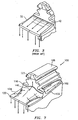
- the turbine blade 30 has a platform 32, an airfoil portion 34 (only a portion of which is shown) radially extending from the platform 32, and an attachment portion 36.
- the attachment portion typically includes a dovetail portion 38 for connecting the blade 30 to a rotating disk (not shown), a neck portion 40, and a buttress portion 42 which extends between the neck portion 40 and an underside 44 of the platform 32.
- the lower speeds and temperatures faced by certain blades allow the airfoil portion to have short root necks and buttresses that adjoin to serrations.
- the buttress portion 42 serves to minimize secondary flow leakage. Blades which face higher stress and temperature have airfoils which use side plates to cover the leakage area between the buttress and the serrations.
- Some turbine blades have a relatively large leading edge platform which is necessary to minimize flowpath leakage between the blade and vane.
- the large overhang of the platform, high rotor speed, short root neck, and relatively high temperature create a stress concentration where the upper serration meets the suction side and pressure side buttresses.
- a turbine blade having the features of the preamble of claim 1 is disclosed in US-B1-6506016 .
- a turbine blade of the present invention is provided with a system for redistributing a load path away from the buttress portion of the turbine blade.
- the turbine blade 100 has a platform 102, an airfoil portion 104 radially extending from a first side 106 of the platform 102, and an attachment portion 108 extending from a second side or underside 110 of the platform 102.
- the attachment portion 108 includes a dovetail portion 112 for securing the turbine blade 100 in a slot (not shown) in a rotor (not shown), such as a disk.
- the attachment portion 108 further includes a neck portion 114 between the dovetail portion 112 and the second side 110 of the platform 102.
- the attachment portion 108 has a buttress 116 between the second side 110 of the platform 102 and the leading end of the neck portion 114. During operation, the buttress 116 as previously discussed is subject to stress.
- the platform 102 has a leading edge 120, a suction side 122, a leading edge root face 123, and a pressure side 124.
- the platform leading edge 120 has a thickness T1.
- the suction side 122 and the pressure side 124 each have a thickness T2.
- the platform further has a central longitudinal axis 126.
- the leading edge of the platform 102 is provided with additional material 140 so as to redistribute the load away from the buttress 116 towards the center of the leading edge root face 123.
- This additional material 140 is preferably the same material that is being used to form the platform 102 and the turbine blade 100.
- the additional material 140 may be formed during the casting of the turbine blade 100.
- the additional material 140 has a shape similar to that of a platypus bill.
- FIG. 8 there is shown a contour map of an exemplary additional material formation which comprises a system for redistributing the loads away from the buttress 116.
- the thicknesses of the additional material 140 for the various points 1 - 24 shown in FIG. 8 are listed in Table I. The thicknesses are given as normalized percentages with the largest thickness at the thickest point 5 being 100%.
- TABLE I PT NO. 1 2 3 4 5 6 7 8 THICKNESS 41.8 53.8 70.6 93.5 100 73.5 57.1 45.3 PT NO. 9 10 11 12 13 14 15 16 THICKNESS 34.1 43.5 52.4 57.7 55.9 48.2 38.8 31.2 PT NO. 17 18 19 20 21 22 23 24 THICKNESS 30.0 34.7 38.9 40.6 38.8 34.1 30.0 27.1
- the thicknesses 1 - 24 are taken along three lines A, B, and C in the region between the front root face 121 and the leading edge 120.
- Line A is located closest to the buttress 116 at a normalized distance of about 13.51% from the front root face 121.
- Line B is located at a normalized distance of about 47.30% from the front root face 121 and line C is located at a normalized distance of about 88.59% from the front root face 121.
- the thickness of the additional material 140 on the second side 110 gradually increases from both the suction side 122 and the pressure side 124 towards a maximum point 5 (on line A), 13 (on line B), and 21 (on line C), which maximum point is preferably offset from the central longitudinal axis 126.
- the thickness of the platform 102 on the second side 110 gradually increases from points along line C, nearest to the leading edge 120, to the point 5.
- the additional material 140 is advantageous in that it distributes loads, both stress and strain, away from the buttress 116 towards the center of leading edge root face 123. This is different from conventional blades where the loads are funneled into the middle and distributed along the entire width of the leading edge of the platform.
Landscapes
- Engineering & Computer Science (AREA)
- Mechanical Engineering (AREA)
- General Engineering & Computer Science (AREA)
- Architecture (AREA)
- Turbine Rotor Nozzle Sealing (AREA)
Claims (15)
- Schaufel (100) zur Verwendung in einem Gasturbinentriebwerk, umfassend:eine Plattform (102), einen Profilabschnitt (104), der sich radial von einer ersten Seite (106) der Plattform (102) erstreckt, und einen Anbringungsabschnitt (108), der sich von einer zweiten Seite (110) der Plattform (102) erstreckt, wobei die Plattform (102) eine Druckseite (124), eine Ansaugseite (122), eine Vorderkante (120) und eine Dicke (T1) an der Vorderkante (120) aufweist;wobei der Anbringungsabschnitt (108) eine Strebpfeiler (116) aufweist, der an der zweiten Seite (110) der Plattform (102) anliegt; unddadurch gekennzeichnet, dass:die zweite Seite (110) ein Mittel (140) zum Umverteilen von Last fort von dem Strebpfeiler (116) aufweist, wobei das Mittel eine konturierte Konfiguration umfasst, wobei eine Dicke von einer Druckseite oder einer Ansaugseite der Plattform aus zunimmt und mit eine erste Region, mit einer ersten Dicke, die größer als die Dicke (T1) an der Vorderkante ist, und eine zweite Region mit einer zweiten Dicke aufweist, die größer als die erste Dicke ist.
- Schaufel nach Anspruch 1, wobei die Plattform (102) eine Ansaugseite (122) und eine Druckseite (124) aufweist und wobei das Lastumverteilungsmittel (140) ein Mittel zum Lenken der Last nach außen zu einer Mitte der Vorderkantenfußfläche (123) umfasst.
- Schaufel nach Anspruch 1 oder 2, wobei die Plattform (102) eine mittlere Längsachse (126) aufweist und die erste und zweite Region gegenüber der mittleren Längsachse (126) versetzt sind.
- Schaufel nach Anspruch 3, wobei die erste Region in der Nähe der Vorderkante (120) der Plattform ist und die zweite Region an dem Strebpfeiler (116) anliegt.
- Schaufel nach einem der vorangehenden Ansprüche, wobei die Ansaugseite (122) eine Dicke (T2) aufweist und das Mittel zum Umverteilen der Last eine dritte Region umfasst, die gegenüber einem Mittelpunkt des Strebpfeilers (116) versetzt ist, und die Dicke in der dritten Region größer als die Dicke (T2) auf der Ansaugseite (122) ist.
- Schaufel nach Anspruch 5, wobei die Plattform (102) eine Dicke aufweist, die von der Ansaugseite (122) zur dritten Region zunimmt.
- Schaufel nach Anspruch 5 oder 6, wobei die Druckseite (124) eine Dicke (T2) aufweist und die Dicke an der dritten Region größer als die Dicke (T2) auf der Druckseite (124) ist.
- Schaufel nach Anspruch 7, wobei die Dicke der Plattform (102) von der Druckseite (124) zur dritten Region zunimmt.
- Schaufel nach einem der vorangehenden Ansprüche, wobei das Lastumverteilungsmittel zusätzliches Material (140) umfasst, das auf der zweiten Seite (110) der Plattform (102) angeordnet ist.
- Schaufel nach einem der vorangehenden Ansprüche, wobei die zweite Seite (110) eine Unterseite der Plattform (102) ist.
- Schaufel nach Anspruch 1, wobei:der Anbringungsabschnitt (108) einen Halsabschnitt (114) aufweist, der sich von der zweiten Seite (110) der Plattform (102) aus erstreckt; undder Strebpfeiler (116) benachbart zu einem Schnittpunkt des Halsabschnitts (114) und der zweiten Seite (110) angeordnet ist;und das Lastumverteilungsmittel zusätzliches Material (140) umfasst, das an der zweiten Seite (110) der Plattform (102) gebildet ist.
- Turbinenschaufel nach Anspruch 11, ferner umfassend:dass das zusätzliche Material (140) an einem ersten Punkt in der Nähe der Vorderseite (120) beginnt und zu einem zweiten Punkt in Anlage an dem Strebpfeiler (116) hin an Dicke zunimmt;dass das zusätzliche Material (140) an einem dritten Punkt in benachbart zur Ansaugseite (122) beginnt und zu von dem dritten Punkt zum zweiten Punkt hin an Dicke zunimmt; unddass das zusätzliche Material (140) ferner an einem vierten Punkt benachbart zu der Druckseite (124) beginnt und von dem vierten Punkt zum zweiten Punkt hin an Dicke zunimmt.
- Turbinenschaufel nach Anspruch 12, ferner umfassend, dass die Plattform (102) eine mittlere Längsachse (126) aufweist und der zweite Punkt gegenüber der mittleren Längsachse (126) versetzt ist.
- Turbinenschaufel nach Anspruch 13, wobei der erste Punkt gegenüber der mittleren Längsachse (126) versetzt ist.
- Turbinenschaufel nach einem der Ansprüche 11 bis 14, wobei der Profilabschnitt (104) ein fliegend gelagerter Profilabschnitt ist.
Applications Claiming Priority (1)
| Application Number | Priority Date | Filing Date | Title |
|---|---|---|---|
| US11/197,162 US20070031260A1 (en) | 2005-08-03 | 2005-08-03 | Turbine airfoil platform platypus for low buttress stress |
Publications (3)
| Publication Number | Publication Date |
|---|---|
| EP1749970A2 EP1749970A2 (de) | 2007-02-07 |
| EP1749970A3 EP1749970A3 (de) | 2010-05-26 |
| EP1749970B1 true EP1749970B1 (de) | 2015-05-13 |
Family
ID=37387422
Family Applications (1)
| Application Number | Title | Priority Date | Filing Date |
|---|---|---|---|
| EP20060252876 Ceased EP1749970B1 (de) | 2005-08-03 | 2006-06-02 | Verlängerung der Plattform einer Turbinenschaufel mit einer niedrigen Spannung in seinem Stützpfeiler |
Country Status (6)
| Country | Link |
|---|---|
| US (1) | US20070031260A1 (de) |
| EP (1) | EP1749970B1 (de) |
| JP (1) | JP2007040295A (de) |
| CN (1) | CN1908379A (de) |
| SG (1) | SG130114A1 (de) |
| TW (1) | TW200710319A (de) |
Families Citing this family (4)
| Publication number | Priority date | Publication date | Assignee | Title |
|---|---|---|---|---|
| DE102010004854A1 (de) * | 2010-01-16 | 2011-07-21 | MTU Aero Engines GmbH, 80995 | Laufschaufel für eine Strömungsmaschine und Strömungsmaschine |
| US9976433B2 (en) * | 2010-04-02 | 2018-05-22 | United Technologies Corporation | Gas turbine engine with non-axisymmetric surface contoured rotor blade platform |
| WO2019136672A1 (zh) * | 2018-01-11 | 2019-07-18 | 贵州智慧能源科技有限公司 | 基于样条曲线设计的涡轮叶片缘板 |
| FR3107301B1 (fr) * | 2020-02-19 | 2022-03-11 | Safran Aircraft Engines | aube pour roue aubagée mobile de turbomachine d’aéronef comprenant un becquet d’étanchéité à section évolutive optimisée |
Family Cites Families (12)
| Publication number | Priority date | Publication date | Assignee | Title |
|---|---|---|---|---|
| US2807436A (en) * | 1952-03-25 | 1957-09-24 | Gen Motors Corp | Turbine wheel and bucket assembly |
| US4259037A (en) * | 1976-12-13 | 1981-03-31 | General Electric Company | Liquid cooled gas turbine buckets |
| GB2228541B (en) * | 1989-02-23 | 1993-04-14 | Rolls Royce Plc | Device for damping vibrations in turbomachinery blades |
| US5302085A (en) * | 1992-02-03 | 1994-04-12 | General Electric Company | Turbine blade damper |
| FR2712631B1 (fr) * | 1993-11-19 | 1998-08-21 | Gen Electric | Ailette de rotor et ensemble ailettes-disque de rotor comportant une telle ailette. |
| FR2743845B1 (fr) * | 1996-01-23 | 1998-02-20 | Snecma | Aube mobile de soufflante a profil de securite |
| US6158962A (en) * | 1999-04-30 | 2000-12-12 | General Electric Company | Turbine blade with ribbed platform |
| US6511294B1 (en) * | 1999-09-23 | 2003-01-28 | General Electric Company | Reduced-stress compressor blisk flowpath |
| US6561761B1 (en) * | 2000-02-18 | 2003-05-13 | General Electric Company | Fluted compressor flowpath |
| US6422820B1 (en) * | 2000-06-30 | 2002-07-23 | General Electric Company | Corner tang fan blade |
| US6506016B1 (en) * | 2001-11-15 | 2003-01-14 | General Electric Company | Angel wing seals for blades of a gas turbine and methods for determining angel wing seal profiles |
| FR2851285B1 (fr) * | 2003-02-13 | 2007-03-16 | Snecma Moteurs | Realisation de turbines pour turbomachines ayant des aubes a frequences de resonance ajustees differentes et procede d'ajustement de la frequence de resonance d'une aube de turbine |
-
2005
- 2005-08-03 US US11/197,162 patent/US20070031260A1/en not_active Abandoned
-
2006
- 2006-04-24 TW TW095114575A patent/TW200710319A/zh unknown
- 2006-05-29 JP JP2006147671A patent/JP2007040295A/ja active Pending
- 2006-06-02 CN CNA2006100887133A patent/CN1908379A/zh active Pending
- 2006-06-02 EP EP20060252876 patent/EP1749970B1/de not_active Ceased
- 2006-08-02 SG SG200605221-1A patent/SG130114A1/en unknown
Also Published As
| Publication number | Publication date |
|---|---|
| TW200710319A (en) | 2007-03-16 |
| SG130114A1 (en) | 2007-03-20 |
| JP2007040295A (ja) | 2007-02-15 |
| US20070031260A1 (en) | 2007-02-08 |
| CN1908379A (zh) | 2007-02-07 |
| EP1749970A3 (de) | 2010-05-26 |
| EP1749970A2 (de) | 2007-02-07 |
Similar Documents
| Publication | Publication Date | Title |
|---|---|---|
| EP1953343B1 (de) | Kühlsystem für eine Gasturbinenschaufel und enstprechende Gasturbinenschaufel | |
| EP2752557B1 (de) | Turbinenschaufel ohne Plattform | |
| US7549846B2 (en) | Turbine blades | |
| US7351035B2 (en) | Hollow rotor blade for the turbine of a gas turbine engine, the blade being fitted with a “bathtub” | |
| US6669445B2 (en) | Endwall shape for use in turbomachinery | |
| JP4179921B2 (ja) | 根元ノッチ付きタービンブレード | |
| EP1882816B1 (de) | Radial geteilter Mikrokühlkreis | |
| US6506022B2 (en) | Turbine blade having a cooled tip shroud | |
| EP1561900B1 (de) | Kühlkreislauf für Turbinenschaufelplattform | |
| US7059834B2 (en) | Turbine blade | |
| EP1726782B1 (de) | Konfiguration der Abströmkante einer Turbinenschaufel | |
| EP2228518B1 (de) | Gasturbinenschaufel mit gekühlter Plattform | |
| EP1270141A2 (de) | Verfahren zum Reparieren von Rissen in der Hinterkantenwurzel einer Turbinenschaufel | |
| EP2022941B1 (de) | Turbinenschaufel von einem Gasturbinentriebwerk | |
| US7273353B2 (en) | Shroud honeycomb cutter | |
| JP2008128234A (ja) | 二重送り蛇行冷却ブレード | |
| EP1887186A2 (de) | Vorderkantenkühlung mit Mikroschaltungs-Anticoriolis-Vorrichtung | |
| US7094032B2 (en) | Turbine blade shroud cutter tip | |
| US20050265841A1 (en) | Cooled rotor blade | |
| EP1749970A2 (de) | Verlängerung der Plattform einer Turbinenschaufel mit einer niedrigen Spannung in seinem Stützpfeiler | |
| US7399163B2 (en) | Rotor blade for a compressor or a gas turbine | |
| US7708528B2 (en) | Platform mate face contours for turbine airfoils | |
| EP1618287B1 (de) | Turbinenschaufel mit gekrümmten hinteren schaftwänden zur spannungsverminderung | |
| US20090136358A1 (en) | Blade cooling | |
| KR20070016928A (ko) | 낮은 버팀벽 응력을 위한 터빈 에어포일 플랫폼 플래티퍼스 |
Legal Events
| Date | Code | Title | Description |
|---|---|---|---|
| PUAI | Public reference made under article 153(3) epc to a published international application that has entered the european phase |
Free format text: ORIGINAL CODE: 0009012 |
|
| AK | Designated contracting states |
Kind code of ref document: A2 Designated state(s): AT BE BG CH CY CZ DE DK EE ES FI FR GB GR HU IE IS IT LI LT LU LV MC NL PL PT RO SE SI SK TR |
|
| AX | Request for extension of the european patent |
Extension state: AL BA HR MK YU |
|
| PUAL | Search report despatched |
Free format text: ORIGINAL CODE: 0009013 |
|
| AK | Designated contracting states |
Kind code of ref document: A3 Designated state(s): AT BE BG CH CY CZ DE DK EE ES FI FR GB GR HU IE IS IT LI LT LU LV MC NL PL PT RO SE SI SK TR |
|
| AX | Request for extension of the european patent |
Extension state: AL BA HR MK YU |
|
| 17P | Request for examination filed |
Effective date: 20101125 |
|
| AKX | Designation fees paid |
Designated state(s): DE GB |
|
| GRAP | Despatch of communication of intention to grant a patent |
Free format text: ORIGINAL CODE: EPIDOSNIGR1 |
|
| INTG | Intention to grant announced |
Effective date: 20141215 |
|
| GRAS | Grant fee paid |
Free format text: ORIGINAL CODE: EPIDOSNIGR3 |
|
| GRAA | (expected) grant |
Free format text: ORIGINAL CODE: 0009210 |
|
| AK | Designated contracting states |
Kind code of ref document: B1 Designated state(s): DE GB |
|
| REG | Reference to a national code |
Ref country code: GB Ref legal event code: FG4D |
|
| REG | Reference to a national code |
Ref country code: DE Ref legal event code: R096 Ref document number: 602006045413 Country of ref document: DE Effective date: 20150625 |
|
| REG | Reference to a national code |
Ref country code: DE Ref legal event code: R097 Ref document number: 602006045413 Country of ref document: DE |
|
| PLBE | No opposition filed within time limit |
Free format text: ORIGINAL CODE: 0009261 |
|
| STAA | Information on the status of an ep patent application or granted ep patent |
Free format text: STATUS: NO OPPOSITION FILED WITHIN TIME LIMIT |
|
| 26N | No opposition filed |
Effective date: 20160216 |
|
| REG | Reference to a national code |
Ref country code: DE Ref legal event code: R082 Ref document number: 602006045413 Country of ref document: DE Representative=s name: SCHMITT-NILSON SCHRAUD WAIBEL WOHLFROM PATENTA, DE |
|
| PGFP | Annual fee paid to national office [announced via postgrant information from national office to epo] |
Ref country code: DE Payment date: 20190521 Year of fee payment: 14 |
|
| REG | Reference to a national code |
Ref country code: DE Ref legal event code: R119 Ref document number: 602006045413 Country of ref document: DE |
|
| PG25 | Lapsed in a contracting state [announced via postgrant information from national office to epo] |
Ref country code: DE Free format text: LAPSE BECAUSE OF NON-PAYMENT OF DUE FEES Effective date: 20210101 |
|
| PGFP | Annual fee paid to national office [announced via postgrant information from national office to epo] |
Ref country code: GB Payment date: 20240521 Year of fee payment: 19 |
|
| GBPC | Gb: european patent ceased through non-payment of renewal fee |
Effective date: 20250602 |
|
| PG25 | Lapsed in a contracting state [announced via postgrant information from national office to epo] |
Ref country code: GB Free format text: LAPSE BECAUSE OF NON-PAYMENT OF DUE FEES Effective date: 20250602 |