EP1749902A2 - Revêtement à base d'une composition résistant à l'usure et composant ayant cette revêtement - Google Patents
Revêtement à base d'une composition résistant à l'usure et composant ayant cette revêtement Download PDFInfo
- Publication number
- EP1749902A2 EP1749902A2 EP06253871A EP06253871A EP1749902A2 EP 1749902 A2 EP1749902 A2 EP 1749902A2 EP 06253871 A EP06253871 A EP 06253871A EP 06253871 A EP06253871 A EP 06253871A EP 1749902 A2 EP1749902 A2 EP 1749902A2
- Authority
- EP
- European Patent Office
- Prior art keywords
- component
- percent
- wear
- resistant coating
- coating mixture
- Prior art date
- Legal status (The legal status is an assumption and is not a legal conclusion. Google has not performed a legal analysis and makes no representation as to the accuracy of the status listed.)
- Withdrawn
Links
- 238000000576 coating method Methods 0.000 title claims abstract description 64
- 239000011248 coating agent Substances 0.000 title claims abstract description 61
- 239000000203 mixture Substances 0.000 title claims abstract description 59
- 239000000758 substrate Substances 0.000 claims abstract description 45
- PXHVJJICTQNCMI-UHFFFAOYSA-N Nickel Chemical compound [Ni] PXHVJJICTQNCMI-UHFFFAOYSA-N 0.000 claims abstract description 44
- XEEYBQQBJWHFJM-UHFFFAOYSA-N Iron Chemical compound [Fe] XEEYBQQBJWHFJM-UHFFFAOYSA-N 0.000 claims abstract description 38
- 229910045601 alloy Inorganic materials 0.000 claims abstract description 34
- 239000000956 alloy Substances 0.000 claims abstract description 34
- 229910052759 nickel Inorganic materials 0.000 claims abstract description 22
- 229910052742 iron Inorganic materials 0.000 claims abstract description 19
- 229910052710 silicon Inorganic materials 0.000 claims abstract description 19
- 239000010703 silicon Substances 0.000 claims abstract description 19
- ZOXJGFHDIHLPTG-UHFFFAOYSA-N Boron Chemical compound [B] ZOXJGFHDIHLPTG-UHFFFAOYSA-N 0.000 claims abstract description 17
- 229910052796 boron Inorganic materials 0.000 claims abstract description 17
- VYZAMTAEIAYCRO-UHFFFAOYSA-N Chromium Chemical compound [Cr] VYZAMTAEIAYCRO-UHFFFAOYSA-N 0.000 claims abstract description 12
- 229910052804 chromium Inorganic materials 0.000 claims abstract description 12
- 239000011651 chromium Substances 0.000 claims abstract description 12
- FXNGWBDIVIGISM-UHFFFAOYSA-N methylidynechromium Chemical compound [Cr]#[C] FXNGWBDIVIGISM-UHFFFAOYSA-N 0.000 claims description 3
- 239000003575 carbonaceous material Substances 0.000 claims description 2
- 238000013459 approach Methods 0.000 description 14
- 239000011230 binding agent Substances 0.000 description 13
- 239000011247 coating layer Substances 0.000 description 12
- 238000002844 melting Methods 0.000 description 12
- 239000000463 material Substances 0.000 description 10
- 238000005219 brazing Methods 0.000 description 8
- UFGZSIPAQKLCGR-UHFFFAOYSA-N chromium carbide Chemical compound [Cr]#C[Cr]C#[Cr] UFGZSIPAQKLCGR-UHFFFAOYSA-N 0.000 description 8
- 238000000034 method Methods 0.000 description 8
- 229910003470 tongbaite Inorganic materials 0.000 description 8
- 239000007789 gas Substances 0.000 description 6
- 238000005304 joining Methods 0.000 description 5
- 239000002245 particle Substances 0.000 description 5
- 238000004519 manufacturing process Methods 0.000 description 4
- 238000012545 processing Methods 0.000 description 4
- 239000007787 solid Substances 0.000 description 4
- 239000000853 adhesive Substances 0.000 description 3
- 230000001070 adhesive effect Effects 0.000 description 3
- 239000010941 cobalt Substances 0.000 description 3
- 229910017052 cobalt Inorganic materials 0.000 description 3
- GUTLYIVDDKVIGB-UHFFFAOYSA-N cobalt atom Chemical compound [Co] GUTLYIVDDKVIGB-UHFFFAOYSA-N 0.000 description 3
- 238000010438 heat treatment Methods 0.000 description 3
- 230000008018 melting Effects 0.000 description 3
- 239000000843 powder Substances 0.000 description 3
- OKTJSMMVPCPJKN-UHFFFAOYSA-N Carbon Chemical compound [C] OKTJSMMVPCPJKN-UHFFFAOYSA-N 0.000 description 2
- 229910052799 carbon Inorganic materials 0.000 description 2
- 239000000567 combustion gas Substances 0.000 description 2
- 238000009713 electroplating Methods 0.000 description 2
- 239000000446 fuel Substances 0.000 description 2
- 239000007791 liquid phase Substances 0.000 description 2
- WPBNNNQJVZRUHP-UHFFFAOYSA-L manganese(2+);methyl n-[[2-(methoxycarbonylcarbamothioylamino)phenyl]carbamothioyl]carbamate;n-[2-(sulfidocarbothioylamino)ethyl]carbamodithioate Chemical compound [Mn+2].[S-]C(=S)NCCNC([S-])=S.COC(=O)NC(=S)NC1=CC=CC=C1NC(=S)NC(=O)OC WPBNNNQJVZRUHP-UHFFFAOYSA-L 0.000 description 2
- 239000011159 matrix material Substances 0.000 description 2
- 239000000155 melt Substances 0.000 description 2
- 238000005245 sintering Methods 0.000 description 2
- ZOKXTWBITQBERF-UHFFFAOYSA-N Molybdenum Chemical compound [Mo] ZOKXTWBITQBERF-UHFFFAOYSA-N 0.000 description 1
- 229910018487 Ni—Cr Inorganic materials 0.000 description 1
- RTAQQCXQSZGOHL-UHFFFAOYSA-N Titanium Chemical compound [Ti] RTAQQCXQSZGOHL-UHFFFAOYSA-N 0.000 description 1
- QCWXUUIWCKQGHC-UHFFFAOYSA-N Zirconium Chemical compound [Zr] QCWXUUIWCKQGHC-UHFFFAOYSA-N 0.000 description 1
- 239000003082 abrasive agent Substances 0.000 description 1
- 239000003990 capacitor Substances 0.000 description 1
- VNNRSPGTAMTISX-UHFFFAOYSA-N chromium nickel Chemical compound [Cr].[Ni] VNNRSPGTAMTISX-UHFFFAOYSA-N 0.000 description 1
- 238000004140 cleaning Methods 0.000 description 1
- 239000012612 commercial material Substances 0.000 description 1
- 238000010276 construction Methods 0.000 description 1
- 238000001816 cooling Methods 0.000 description 1
- 238000010586 diagram Methods 0.000 description 1
- 238000007606 doctor blade method Methods 0.000 description 1
- 238000005516 engineering process Methods 0.000 description 1
- 238000001125 extrusion Methods 0.000 description 1
- 238000010285 flame spraying Methods 0.000 description 1
- 238000000227 grinding Methods 0.000 description 1
- 238000003754 machining Methods 0.000 description 1
- 229910001092 metal group alloy Inorganic materials 0.000 description 1
- 238000012986 modification Methods 0.000 description 1
- 230000004048 modification Effects 0.000 description 1
- 229910052750 molybdenum Inorganic materials 0.000 description 1
- 239000011733 molybdenum Substances 0.000 description 1
- 239000011368 organic material Substances 0.000 description 1
- 239000012071 phase Substances 0.000 description 1
- 238000012805 post-processing Methods 0.000 description 1
- 238000003825 pressing Methods 0.000 description 1
- 238000005096 rolling process Methods 0.000 description 1
- 238000007493 shaping process Methods 0.000 description 1
- 238000007711 solidification Methods 0.000 description 1
- 230000008023 solidification Effects 0.000 description 1
- 229910052715 tantalum Inorganic materials 0.000 description 1
- GUVRBAGPIYLISA-UHFFFAOYSA-N tantalum atom Chemical compound [Ta] GUVRBAGPIYLISA-UHFFFAOYSA-N 0.000 description 1
- 239000010936 titanium Substances 0.000 description 1
- 229910052719 titanium Inorganic materials 0.000 description 1
- WFKWXMTUELFFGS-UHFFFAOYSA-N tungsten Chemical compound [W] WFKWXMTUELFFGS-UHFFFAOYSA-N 0.000 description 1
- 229910052721 tungsten Inorganic materials 0.000 description 1
- 239000010937 tungsten Substances 0.000 description 1
- 238000003466 welding Methods 0.000 description 1
- 238000009736 wetting Methods 0.000 description 1
- 229910052726 zirconium Inorganic materials 0.000 description 1
Images

Classifications
-
- C—CHEMISTRY; METALLURGY
- C23—COATING METALLIC MATERIAL; COATING MATERIAL WITH METALLIC MATERIAL; CHEMICAL SURFACE TREATMENT; DIFFUSION TREATMENT OF METALLIC MATERIAL; COATING BY VACUUM EVAPORATION, BY SPUTTERING, BY ION IMPLANTATION OR BY CHEMICAL VAPOUR DEPOSITION, IN GENERAL; INHIBITING CORROSION OF METALLIC MATERIAL OR INCRUSTATION IN GENERAL
- C23C—COATING METALLIC MATERIAL; COATING MATERIAL WITH METALLIC MATERIAL; SURFACE TREATMENT OF METALLIC MATERIAL BY DIFFUSION INTO THE SURFACE, BY CHEMICAL CONVERSION OR SUBSTITUTION; COATING BY VACUUM EVAPORATION, BY SPUTTERING, BY ION IMPLANTATION OR BY CHEMICAL VAPOUR DEPOSITION, IN GENERAL
- C23C26/00—Coating not provided for in groups C23C2/00 - C23C24/00
-
- Y—GENERAL TAGGING OF NEW TECHNOLOGICAL DEVELOPMENTS; GENERAL TAGGING OF CROSS-SECTIONAL TECHNOLOGIES SPANNING OVER SEVERAL SECTIONS OF THE IPC; TECHNICAL SUBJECTS COVERED BY FORMER USPC CROSS-REFERENCE ART COLLECTIONS [XRACs] AND DIGESTS
- Y10—TECHNICAL SUBJECTS COVERED BY FORMER USPC
- Y10T—TECHNICAL SUBJECTS COVERED BY FORMER US CLASSIFICATION
- Y10T428/00—Stock material or miscellaneous articles
- Y10T428/12—All metal or with adjacent metals
- Y10T428/12493—Composite; i.e., plural, adjacent, spatially distinct metal components [e.g., layers, joint, etc.]
- Y10T428/12535—Composite; i.e., plural, adjacent, spatially distinct metal components [e.g., layers, joint, etc.] with additional, spatially distinct nonmetal component
- Y10T428/12576—Boride, carbide or nitride component
-
- Y—GENERAL TAGGING OF NEW TECHNOLOGICAL DEVELOPMENTS; GENERAL TAGGING OF CROSS-SECTIONAL TECHNOLOGIES SPANNING OVER SEVERAL SECTIONS OF THE IPC; TECHNICAL SUBJECTS COVERED BY FORMER USPC CROSS-REFERENCE ART COLLECTIONS [XRACs] AND DIGESTS
- Y10—TECHNICAL SUBJECTS COVERED BY FORMER USPC
- Y10T—TECHNICAL SUBJECTS COVERED BY FORMER US CLASSIFICATION
- Y10T428/00—Stock material or miscellaneous articles
- Y10T428/12—All metal or with adjacent metals
- Y10T428/12493—Composite; i.e., plural, adjacent, spatially distinct metal components [e.g., layers, joint, etc.]
- Y10T428/12771—Transition metal-base component
- Y10T428/12861—Group VIII or IB metal-base component
- Y10T428/12931—Co-, Fe-, or Ni-base components, alternative to each other
Definitions
- This invention relates to a coating that may be applied to the surface of an article substrate and, in particular, to a multicomponent coating whose properties may be controlled by the selection of the type and amount of the components.
- gas turbine In an aircraft gas turbine (jet) engine, air is drawn into the front of the engine, compressed by a shaft-mounted compressor, and mixed with fuel. The mixture of air and fuel is burned, and the hot combustion gases are passed through a turbine mounted on the same shaft. The flow of combustion gas turns the turbine by impingement against an airfoil section of the turbine blades and vanes, which turns the shaft and provides power to the compressor and fan.
- the compressor and a high-pressure turbine are mounted on one shaft, and the fan and low-pressure turbine are mounted on a separate shaft.
- the hot exhaust gases flow from the back of the engine, driving it and the aircraft forward.
- the compressor and turbine of the gas turbine engine include many pairs of components that contact and rub against each other during operation of the engine.
- the contact and rubbing can cause wear damage to one or both of the components, if allowed to proceed uncontrolled.
- Coatings are often placed onto the surfaces of one or both of the components in order to protect against the damage.
- Such a coating may be hard and abrasive to resist wear damage, or more lubricious to reduce the coefficient of friction and thence the wear damage.
- a variety of techniques are used to apply such wear-resistant coatings to components of gas turbine engines and in other applications. Examples of such techniques include flame spraying, electroplating, and brazing. Each of the techniques has advantages and disadvantages, but in general it is desired to apply the coating of the proper thickness and with acceptable quality and performance to the surface in a controlled manner at minimal cost, in both new-make and repair applications as appropriate.
- the present approach provides a wear-resistant coating mixture and an approach for applying a wear-resistant coating of the mixture to a surface of a component substrate.
- the wear-resistant coating mixture is formed of two (or more) components, one of which is a lower-melting component and the other of which is a higher-melting component.
- the lower-melting first component is a nickel-base alloy having a solidus temperature of about 1775°F-1825°F, which is lower than the melting temperature of other available lower-melting nickel-base compositions used in brazing mixtures.
- the use of such a lower-melting component allows the application of the wear coating during brazing cycles of other portions of the structure, thereby reducing the number of heating cycles required and thence the production costs as compared with application techniques that require separate application cycles.
- the higher-melting second component may be either an abrasive material or a lubricious material. The approach may therefore be used to apply a wear-resistant coating having a second component that is either more abrasive than the first component or is more lubricious than the first component.
- a wear-resistant coating mixture may comprise a first component having a first-component solidus temperature and having a nominal composition in weight percent of (i) from about 6 to about 8 percent chromium, from about 2.5 to about 3.5 percent iron, from about 4 to about 5 percent silicon, from about 2.75 to about 3.5 percent boron, balance nickel and minor elements, or (ii) about 0.5 maximum percent iron, from about 4 to about 5 percent silicon, from about 2.75 to about 3.5 percent boron, balance nickel and minor elements, and a second component having a second-component solidus temperature greater than the first-component solidus temperature.
- the first component preferably has a nominal composition in weight percent of (i) about 82.9 percent nickel, about 7 percent chromium, about 3 percent iron, about 4.1 percent silicon, and about 3 percent boron, or (ii) about 92.4 percent nickel, about 0.2 percent iron, about 4.5 percent silicon, and about 2.9 percent boron.
- the wear-resistant coating mixture may be in a "green" state where the first component has not been melted while in contact with the second component, or a sintered state where at least some of the first component has been melted in contact with the second component.
- a binder preferably an organic binder, that binds the first component and the second component together until the first component has been melted.
- the second component has a second-component abrasiveness greater than the first-component abrasiveness. In another embodiment, the second-component is more lubricious than is the first-component.
- An example of a more-abrasive second component is chromium carbide (CrC), and an example of a more-lubricious second component is a cobalt-base alloy such as Mar M509 or T800.
- a wear-resistant coating mixture comprises a nickel-base alloy first component having a first-component solidus temperature of from about 1775°F to about 1825°F, and a second component having a second-component solidus temperature greater than the first-component solidus temperature.
- the first component preferably has a nominal composition in weight percent of (i) from about 6 to about 8 percent chromium, from about 2.5 to about 3.5 percent iron, from about 4 to about 5 percent silicon, from about 2.75 to about 3.5 percent boron, balance nickel and minor elements, or (ii) about 0.5 maximum percent iron, from about 4 to about 5 percent silicon, from about 2.75 to about 3.5 percent boron, balance nickel and minor elements.
- An article may comprise a substrate having a surface, and a wear-resistant coating mixture applied to the surface of the substrate.
- the wear-resistant coating mixture comprises a nickel-base alloy first component having a first-component solidus temperature of from about 1775°F to about 1825°F, and a second component having a second-component solidus temperature greater than the first-component solidus temperature.
- Other compatible features as discussed above may be used with this embodiment.
- a method for forming a structure may comprise the steps of providing a substrate having a surface, and applying a wear-resistant coating mixture to the surface of the substrate as a wear-resistant coating layer.
- the wear-resistant coating mixture comprises a nickel-base alloy first component having a first-component solidus temperature of from about 1775°F to about 1825°F, and a second component having a second-component solidus temperature greater than the first-component solidus temperature.
- the step of applying includes the step of heating the substrate and the wear-resistant coating mixture to a coating temperature greater than the first-component solidus temperature.
- the first component and the second component are preferably as described above, and other compatible features as described herein may be used with the method.
- Various aspects and embodiments of the present approach thus provide a wear-resistant coating mixture using a nickel-base lower-melting first component that has good strength and adherence properties to typical nickel-base substrates, in combination with a low melting point that results in good economics and reduced manufacturing costs as compared with lower-melting components that melt at increased temperatures.
- Figure 1 depicts an article 20 that comprises a substrate 22 having a surface 24, and a wear-resistant coating mixture 26 applied as a wear-resistant coating layer 28 to the surface 24 of the substrate 22.
- the substrate 22 is preferably a component of a gas turbine engine such as a compressor vane sector. Examples of materials of construction of substrates 22 to which the wear-resistant coating layer 28 may be applied include Alloy 625 and Alloy 718.
- the wear-resistant coating mixture 26 in its green form of Figure 1 comprises a nickel-base alloy first component 30, a second component 32, and a third component 34.
- Green as used herein in reference to the wear-resistant coating mixture, means that the first component 30 has not been melted in contact with the second component 32, and the third component 34 is present.
- the first component 30 and the second component 32 are in the form of small particles, typically of a particle size of -325 mesh.
- the third component 34 is a binder, preferably an organic binder that binds the first component 30 and the second component 32 together, and aids in adhering them to the surface 24.
- the first component 30, which is a low-melting component as compared with the second component 32, has a first-component solidus temperature of from 1775°F to 1825°F.
- This relatively low melting temperature for a nickel-base alloy allows the coating processing (to be described subsequently) to be conducted at a relatively low temperature that is compatible with brazing cycles used for other portions of the manufacture of the component.
- a "nickel-base” alloy has more nickel (by weight) than any other element.
- the nickel-base alloy first component 30 has at least 80 percent by weight nickel. The use of a large weight percentage of nickel makes the first component 30, which is melted during processing, compatible with a nickel-base substrate 22, the preferred application.
- Two preferred nickel-base alloys that may be used as the first component 30 have compositions in weight percent of (i) from 6 to 8 percent chromium, from 2.5 to 3.5 percent iron, from 4 to 5 percent silicon, from 2.75 to 3.5 percent boron, balance nickel and minor elements (alloy AMS 4777), with a preferred composition being 82.9 percent nickel, 7 percent chromium, 3 percent iron, 4.1 percent silicon, and 3 percent boron; or (ii) 0.5 maximum percent iron, from 4 to 5 percent silicon, from 2.75 to 3.5 percent boron, balance nickel and minor elements (alloy AMS 4778), with a preferred composition being 92.4 percent nickel, 0.2 percent iron, 4.5 percent silicon, and 2.9 percent boron.
- the first component 30 has a first-component solidus temperature. Both of these preferred nickel-base alloys have a solidus temperature of about 1800°F.
- the first nickel-base alloy has a liquidus temperature of about 1825°F and a preferred coating temperature of about 1950 +/- 25°F.
- the second nickel-base alloy has a liquidus temperature of about 1875°F and a preferred coating temperature of about 1950 +/- 25°F.
- the second component 32 is of a different composition than the first component.
- the second component 32 has a second-component solidus temperature greater than the first-component solidus temperature. That is, there is an intermediate temperature range at which the first component 30 melts but the second component 32 does not melt.
- the coating temperature preferably lies in this intermediate temperature range.
- the second component is selected according to whether the second-component is more abrasive than the first component, or whether the second component is more lubricious than the first component.
- An example wherein the second component is more abrasive than the first component is chromium-carbon material such as CrC.
- CrC When CrC is used, it is preferably provided as a prealloyed powder of CrC and nickel-chromium metallic alloy to facilitate wetting of the melted first component to the CrC.
- a preferred composition in weight percent is 3.5-4.5 percent carbon, 7.0-9.0 percent nickel, 1.5 percent maximum manganese, 0.7 percent maximum iron, 1.5 percent maximum silicon, 2.0 maximum percent all other elements except chromium, balance chromium.
- An example of a second component wherein the second component is more lubricious than the first component is a cobalt-base alloy such as Mar M509, having a nominal composition in weight percent of about 0.6 percent carbon, about 0.1 percent manganese, about 0.4 percent maximum silicon, about 22.5-24.25 percent chromium, about 1.5 percent maximum iron, about 0.15-0.30 percent titanium, about 0.01 percent maximum boron, about 0.3-0.6 percent zirconium, about 9-11 percent nickel, about 6.5-7.5 percent tungsten, about 3-4 percent tantalum, balance cobalt and minor elements; or alloy T800, having a nominal composition in weight percent of from about 16.5 to about 18.5 percent chromium, from about 27 to about 30 percent molybdenum, about 3 to about 3.8 weight percent silicon, about 1.5 maximum percent iron, about 1.5 percent maximum nickel, balance cobalt, with minor elements also present.
- a cobalt-base alloy such as Mar M509, having a nominal composition in weight percent of about 0.6 percent carbon, about
- Some preferred relative amounts of the second component 32 and the first component 30 in weight percents are from 18 to 30 percent, preferably from 25 to 27 percent, most preferably 27 percent CrC (chromium carbide), balance alloy 4778; from 10 to 20 percent, preferably from 14 to 16 percent, most preferably 15 percent alloy T800, balance alloy 4777; from 15 to 35 percent, preferably from 25 to 28 percent, most preferably 27 percent Mar M509, balance alloy 4777; and from 15 to 50 percent, preferably from 37 to 41 percent, most preferably 40 percent Mar M509, balance alloy 4778.
- These preferred relative amounts are selected so that the melted material has the proper fluidity, and to achieve an acceptable surface finish in the final solidified product.
- the third component 34 of the green wear-resistant coating mixture 26 illustrated in Figure 1 is the binder.
- the binder is preferably an organic material that aids in adhering and binding the first component 30 and the second component 32 together to each other and to the surface 24 during initial handling and in the green form on the substrate surface 24.
- Commercial materials such as Nicrobraze 520 and Nicrobraze 1000 may be used as the third-component 34, as these binders vaporize in a subsequent step leaving little residue.
- Nicrobraze 520 and Nicrobraze 1000 may be used as the third-component 34, as these binders vaporize in a subsequent step leaving little residue.
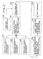
- Figure 2 illustrates the steps of a method for practicing an aspect of the present approach.
- a powder of the first component 30 is provided, step 40; a powder of the second component 32 is provided, step 42, and the binder component 34 is provided, step 44.
- the components 30, 32, and 34 are as described previously.
- the relative proportions of the components 30 and 32 are preferably as described above.
- the binder third component 34 is typically about 10 percent by weight of the total weight of the first component 30 and the second component 32.
- the three components 30, 32, and 34 are mixed together and, preferably, formed into a tape, step 46, by any operable approach, such as rolling, extrusion, doctor blade technique, or the like.
- the tape may be of any operable thickness and width. A preferred thickness is about 0.010 inches or less, and the tape is made as wide as necessary to cover the area to be coated.
- the tape may be made in short segments or substantially continuous, and in the latter approach appropriate lengths are cut off as needed.
- the tape may be used in this "green" form wherein the first component has not been melted at all in the tape, or optionally fired to partially pre-sinter the tape.
- the tape is heated to a pre-sintering temperature where a small portion of the first component partially melts but the second component does not melt.
- the binder is vaporized. The binder is no longer needed, as the partially melted first component holds the remainder of the first component and the second component together with sufficient strength for subsequent handling and joining to the substrate.
- the substrate 22 is provided, step 48.
- the substrate 22 is preferably made of a nickel-base alloy such as Alloy 625 or Alloy 718, although other types of alloys may be used as well.
- the green tape or pre-sintered tape prepared in step 46 is joined to the surface 24 of the substrate 22, step 50. At this stage, the joining of the green tape or pre-sintered tape to the surface 24 need be only sufficient to hold the tape in place for the initial stages of the next step. For some applications, a pressing onto the surface may be sufficient in step 50. In other applications, an adhesive such as Borden's SAF-T may be used as a temporary adhesive.
- the pre-sintered tape may be joined to the surface 24 by a tack weld such as produced by capacitor discharge welding.
- the substrate 22 with the applied wear-resistant coating mixture of the components 30, 32, and 34 is heated to a coating temperature, step 52.
- the preferred coating temperature is 1950 +/- 25°F. This coating temperature is significantly lower than those of other available alloys that may be used as the first component.
- the binder third component 34 and the adhesive, if any, are vaporized and removed.
- the first component begins to melt, but the second component 32 remains a solid.
- the liquid phase of the first component 30 begins to partially interdiffuse with the solid particles of the second component 32 and with the substrate material at the surface 24, forming metallurgical bonds.
- a strong metallurgical bond is formed between the phases and the surface 24 as the sintered wear-resistant coating layer 28 is formed. This state is termed a "sintered" state, where the first component 30 has melted but the second component 32 and the substrate 22 have not melted, but there is a degree of interdiffusion due to the liquid phase of the first component 30.
- Figure 3 illustrates the article 20 with the first component 30 and the second component 32 sintered after step 52.
- the first component 30 is no longer in a particle form, but instead is a first-component matrix 36 that binds the particles of the second component 32 (which did not melt in step 52) to each other and to the surface 24 of the substrate.
- the sintered wear-resistant coating layer 28 and substrate 22 are thereafter post processed as necessary.
- Post processing may include shaping the wear-resistant coating layer 28 as necessary, for example by grinding or machining. It may also include further heat-treating, cleaning, or other processing.
- a wear shoe made of Alloy 718 was coated with the indicated shoe coating.
- the coated shoe was worn in sliding friction against a block made of Alloy 718 and coated with T104CS material, at a temperature of 950°F.
- the stroke cycle was 0.005 inch length at 100 Hertz (Hz), followed by 0.100 inch length at 1 Hz.
- the T104CS material is a known wear-resistant coating made by electroplating a mixture of cobalt and chromium carbide that is the preferred conventional wear-resistant coating for many applications, and the remaining four shoe coatings are compositions prepared according to embodiments of the present approach. Shoe Coating Average.
- a minus sign (-) indicates a pit, while a positive value indicates a buildup of material.
- Figure 4 illustrates the use of an aspect of the present approach to produce a wear-resistant coating layer 28 on the substrate 22, simultaneously with the brazing of the substrate 22 to another piece 60.
- the method of Figure 2 is used, except that prior to step 52 the substrate 22 is assembled into contact with the piece 60 with a braze joint 62 either prepositioned between the substrate 22 and the piece 60, or with the substrate 22 and the piece 60 spaced apart by a controlled distance, such as about 0.010 inch, and a reservoir of the braze material for the braze joint 62 adjacent to the gap between the substrate 22 and the piece 60, step 56.
- the braze material for the braze joint 62 is selected to have a brazing temperature compatible with the coating temperature of the wear-resistant coating mixture 26.
- step 52 the first component 30 of the wear-resistant coating mixture 26 is melted to form the sintered wear-resistant coating layer 28 illustrated in Figure 3, and simultaneously the braze material is melted to form the braze joint 62.
- the solid wear-resistant coating layer 28 and the solid braze joint 62 remain.
- More complex structures may be built by joining several substrates and pieces together by brazing, simultaneously with the wear-resistant coating of those portions of the structure that are subject to wear damage, in a single heating cycle.
- the substrate 22 may be joined to the piece 60 directly, as illustrated in Figure 4, or indirectly with other elements of structure between the substrate 22 and the piece 60, as long as the wear-resistant coating layer 28 and the braze joint 62 are present and are preferably formed simultaneously as described.
- This combined joining and wear protection is an important cost-saving advance in the processing of subcomponents and components, since braze joining and wear protection with the wear-resistant coating layer are performed in a single step, rather than in multiple steps as with prior approaches.
Landscapes
- Chemical & Material Sciences (AREA)
- Chemical Kinetics & Catalysis (AREA)
- Engineering & Computer Science (AREA)
- Materials Engineering (AREA)
- Mechanical Engineering (AREA)
- Metallurgy (AREA)
- Organic Chemistry (AREA)
- Other Surface Treatments For Metallic Materials (AREA)
Applications Claiming Priority (1)
| Application Number | Priority Date | Filing Date | Title |
|---|---|---|---|
| US11/188,820 US20070037008A1 (en) | 2005-07-25 | 2005-07-25 | Wear-resistant coating mixture and article having the wear-resistant coating mixture applied thereto |
Publications (2)
| Publication Number | Publication Date |
|---|---|
| EP1749902A2 true EP1749902A2 (fr) | 2007-02-07 |
| EP1749902A3 EP1749902A3 (fr) | 2007-11-21 |
Family
ID=37106930
Family Applications (1)
| Application Number | Title | Priority Date | Filing Date |
|---|---|---|---|
| EP06253871A Withdrawn EP1749902A3 (fr) | 2005-07-25 | 2006-07-24 | Revêtement à base d'une composition résistant à l'usure et composant ayant cette revêtement |
Country Status (2)
| Country | Link |
|---|---|
| US (1) | US20070037008A1 (fr) |
| EP (1) | EP1749902A3 (fr) |
Cited By (1)
| Publication number | Priority date | Publication date | Assignee | Title |
|---|---|---|---|---|
| WO2016120068A1 (fr) * | 2015-01-30 | 2016-08-04 | Siemens Aktiengesellschaft | Pièce découpée comprenant un film de brasage fritté sur celle-ci, procédé et composant |
Citations (2)
| Publication number | Priority date | Publication date | Assignee | Title |
|---|---|---|---|---|
| US20020119338A1 (en) | 1999-06-29 | 2002-08-29 | Wayne Charles Hasz | Tubine engine component having wear coating and method for coating a turbine engine component |
| EP1516942A1 (fr) | 2003-09-17 | 2005-03-23 | General Electric Company | Procédé de revêtement d'un substrat |
Family Cites Families (10)
| Publication number | Priority date | Publication date | Assignee | Title |
|---|---|---|---|---|
| DE1198169B (de) * | 1963-04-06 | 1965-08-05 | Deutsche Edelstahlwerke Ag | Karbidhaltiges Pulvergemisch zum Aufspritzen und Aufschweissen von Metallueberzuegen |
| US3678570A (en) * | 1971-04-01 | 1972-07-25 | United Aircraft Corp | Diffusion bonding utilizing transient liquid phase |
| US4008844A (en) * | 1975-01-06 | 1977-02-22 | United Technologies Corporation | Method of repairing surface defects using metallic filler material |
| US4285459A (en) * | 1979-07-31 | 1981-08-25 | Chromalloy American Corporation | High temperature braze repair of superalloys |
| GB8816738D0 (en) * | 1988-07-14 | 1988-08-17 | Rolls Royce Plc | Alloy mix & method of repair of article therewith |
| US5240491A (en) * | 1991-07-08 | 1993-08-31 | General Electric Company | Alloy powder mixture for brazing of superalloy articles |
| US5561827A (en) * | 1994-12-28 | 1996-10-01 | General Electric Company | Coated nickel-base superalloy article and powder and method useful in its preparation |
| US6464128B1 (en) * | 1999-05-28 | 2002-10-15 | General Electric Company | Braze repair of a gas turbine engine stationary shroud |
| US6283356B1 (en) * | 1999-05-28 | 2001-09-04 | General Electric Company | Repair of a recess in an article surface |
| US6679680B2 (en) * | 2002-03-25 | 2004-01-20 | General Electric Company | Built-up gas turbine component and its fabrication |
-
2005
- 2005-07-25 US US11/188,820 patent/US20070037008A1/en not_active Abandoned
-
2006
- 2006-07-24 EP EP06253871A patent/EP1749902A3/fr not_active Withdrawn
Patent Citations (2)
| Publication number | Priority date | Publication date | Assignee | Title |
|---|---|---|---|---|
| US20020119338A1 (en) | 1999-06-29 | 2002-08-29 | Wayne Charles Hasz | Tubine engine component having wear coating and method for coating a turbine engine component |
| EP1516942A1 (fr) | 2003-09-17 | 2005-03-23 | General Electric Company | Procédé de revêtement d'un substrat |
Cited By (1)
| Publication number | Priority date | Publication date | Assignee | Title |
|---|---|---|---|---|
| WO2016120068A1 (fr) * | 2015-01-30 | 2016-08-04 | Siemens Aktiengesellschaft | Pièce découpée comprenant un film de brasage fritté sur celle-ci, procédé et composant |
Also Published As
| Publication number | Publication date |
|---|---|
| EP1749902A3 (fr) | 2007-11-21 |
| US20070037008A1 (en) | 2007-02-15 |
Similar Documents
| Publication | Publication Date | Title |
|---|---|---|
| CA2581908C (fr) | Reparation des anneaux de cerclage d'une turbine haute pression avec des preformes frittees | |
| JP4901107B2 (ja) | 高押圧接触に曝された表面を修復する方法 | |
| CA2445237C (fr) | Methode de reparation d'une enveloppe fixe de turbine a gaz par soudage a l'arc a transfert de plasma | |
| US7335427B2 (en) | Preform and method of repairing nickel-base superalloys and components repaired thereby | |
| US7867628B2 (en) | Brazed articles | |
| US6679680B2 (en) | Built-up gas turbine component and its fabrication | |
| US20060248719A1 (en) | Superalloy repair methods and inserts | |
| US20040086635A1 (en) | Method of repairing a stationary shroud of a gas turbine engine using laser cladding | |
| EP1559868A2 (fr) | Méthode de rétablissement des dimensions d'une aube et préformé pour son application | |
| US20130156555A1 (en) | Braze materials, brazing processes, and components with wear-resistant coatings formed thereby | |
| US7748601B2 (en) | Brazed articles, braze assemblies and methods therefor utilizing gold/copper/nickel brazing alloys | |
| US10654137B2 (en) | Repair of worn component surfaces | |
| US7328832B2 (en) | Gold/nickel/copper brazing alloys for brazing WC-Co to titanium alloys | |
| EP1749902A2 (fr) | Revêtement à base d'une composition résistant à l'usure et composant ayant cette revêtement | |
| US7434720B2 (en) | Gold/nickel/copper/titanium brazing alloys for brazing WC-Co to titanium alloys | |
| US20090011276A1 (en) | Silver/aluminum/copper/titanium nickel/brazing alloys for brazing wc-co to titanium and alloys thereof, brazing methods, and brazed articles | |
| RU2825685C1 (ru) | Предварительно спеченная заготовка с высокой термостойкостью, используемая, в частности, в качестве абразивного покрытия для лопаток газовой турбины | |
| JP2024503811A (ja) | 高温性能を有する、具体的にはガスタービンブレード用研磨コーティングとしての予備焼結プリフォーム |
Legal Events
| Date | Code | Title | Description |
|---|---|---|---|
| PUAI | Public reference made under article 153(3) epc to a published international application that has entered the european phase |
Free format text: ORIGINAL CODE: 0009012 |
|
| AK | Designated contracting states |
Kind code of ref document: A2 Designated state(s): AT BE BG CH CY CZ DE DK EE ES FI FR GB GR HU IE IS IT LI LT LU LV MC NL PL PT RO SE SI SK TR |
|
| AX | Request for extension of the european patent |
Extension state: AL BA HR MK YU |
|
| RAP1 | Party data changed (applicant data changed or rights of an application transferred) |
Owner name: GENERAL ELECTRIC COMPANY |
|
| PUAL | Search report despatched |
Free format text: ORIGINAL CODE: 0009013 |
|
| AK | Designated contracting states |
Kind code of ref document: A3 Designated state(s): AT BE BG CH CY CZ DE DK EE ES FI FR GB GR HU IE IS IT LI LT LU LV MC NL PL PT RO SE SI SK TR |
|
| AX | Request for extension of the european patent |
Extension state: AL BA HR MK YU |
|
| 17P | Request for examination filed |
Effective date: 20080521 |
|
| 17Q | First examination report despatched |
Effective date: 20080625 |
|
| AKX | Designation fees paid |
Designated state(s): DE FR GB |
|
| STAA | Information on the status of an ep patent application or granted ep patent |
Free format text: STATUS: THE APPLICATION IS DEEMED TO BE WITHDRAWN |
|
| 18D | Application deemed to be withdrawn |
Effective date: 20100202 |