EP1749746A2 - Paper-sheet punching device, paper-sheet folding device, and image forming device - Google Patents
Paper-sheet punching device, paper-sheet folding device, and image forming device Download PDFInfo
- Publication number
- EP1749746A2 EP1749746A2 EP06253996A EP06253996A EP1749746A2 EP 1749746 A2 EP1749746 A2 EP 1749746A2 EP 06253996 A EP06253996 A EP 06253996A EP 06253996 A EP06253996 A EP 06253996A EP 1749746 A2 EP1749746 A2 EP 1749746A2
- Authority
- EP
- European Patent Office
- Prior art keywords
- paper sheet
- paper
- punching
- sheet
- delivery
- Prior art date
- Legal status (The legal status is an assumption and is not a legal conclusion. Google has not performed a legal analysis and makes no representation as to the accuracy of the status listed.)
- Granted
Links
Images










Classifications
-
- B—PERFORMING OPERATIONS; TRANSPORTING
- B26—HAND CUTTING TOOLS; CUTTING; SEVERING
- B26F—PERFORATING; PUNCHING; CUTTING-OUT; STAMPING-OUT; SEVERING BY MEANS OTHER THAN CUTTING
- B26F1/00—Perforating; Punching; Cutting-out; Stamping-out; Apparatus therefor
- B26F1/24—Perforating by needles or pins
-
- B—PERFORMING OPERATIONS; TRANSPORTING
- B65—CONVEYING; PACKING; STORING; HANDLING THIN OR FILAMENTARY MATERIAL
- B65H—HANDLING THIN OR FILAMENTARY MATERIAL, e.g. SHEETS, WEBS, CABLES
- B65H29/00—Delivering or advancing articles from machines; Advancing articles to or into piles
- B65H29/58—Article switches or diverters
-
- G—PHYSICS
- G03—PHOTOGRAPHY; CINEMATOGRAPHY; ANALOGOUS TECHNIQUES USING WAVES OTHER THAN OPTICAL WAVES; ELECTROGRAPHY; HOLOGRAPHY
- G03G—ELECTROGRAPHY; ELECTROPHOTOGRAPHY; MAGNETOGRAPHY
- G03G15/00—Apparatus for electrographic processes using a charge pattern
- G03G15/65—Apparatus which relate to the handling of copy material
- G03G15/6538—Devices for collating sheet copy material, e.g. sorters, control, copies in staples form
- G03G15/6541—Binding sets of sheets, e.g. by stapling, glueing
- G03G15/6544—Details about the binding means or procedure
-
- B—PERFORMING OPERATIONS; TRANSPORTING
- B26—HAND CUTTING TOOLS; CUTTING; SEVERING
- B26F—PERFORATING; PUNCHING; CUTTING-OUT; STAMPING-OUT; SEVERING BY MEANS OTHER THAN CUTTING
- B26F1/00—Perforating; Punching; Cutting-out; Stamping-out; Apparatus therefor
- B26F1/0092—Perforating means specially adapted for printing machines
-
- B—PERFORMING OPERATIONS; TRANSPORTING
- B65—CONVEYING; PACKING; STORING; HANDLING THIN OR FILAMENTARY MATERIAL
- B65H—HANDLING THIN OR FILAMENTARY MATERIAL, e.g. SHEETS, WEBS, CABLES
- B65H2301/00—Handling processes for sheets or webs
- B65H2301/30—Orientation, displacement, position of the handled material
- B65H2301/34—Modifying, selecting, changing direction of displacement
- B65H2301/341—Modifying, selecting, changing direction of displacement without change of plane of displacement
- B65H2301/3411—Right angle arrangement, i.e. 90 degrees
- B65H2301/34112—Right angle arrangement, i.e. 90 degrees changing leading edge
-
- B—PERFORMING OPERATIONS; TRANSPORTING
- B65—CONVEYING; PACKING; STORING; HANDLING THIN OR FILAMENTARY MATERIAL
- B65H—HANDLING THIN OR FILAMENTARY MATERIAL, e.g. SHEETS, WEBS, CABLES
- B65H2301/00—Handling processes for sheets or webs
- B65H2301/50—Auxiliary process performed during handling process
- B65H2301/51—Modifying a characteristic of handled material
- B65H2301/515—Cutting handled material
- B65H2301/5152—Cutting partially, e.g. perforating
-
- G—PHYSICS
- G03—PHOTOGRAPHY; CINEMATOGRAPHY; ANALOGOUS TECHNIQUES USING WAVES OTHER THAN OPTICAL WAVES; ELECTROGRAPHY; HOLOGRAPHY
- G03G—ELECTROGRAPHY; ELECTROPHOTOGRAPHY; MAGNETOGRAPHY
- G03G2215/00—Apparatus for electrophotographic processes
- G03G2215/00362—Apparatus for electrophotographic processes relating to the copy medium handling
- G03G2215/00367—The feeding path segment where particular handling of the copy medium occurs, segments being adjacent and non-overlapping. Each segment is identified by the most downstream point in the segment, so that for instance the segment labelled "Fixing device" is referring to the path between the "Transfer device" and the "Fixing device"
- G03G2215/00417—Post-fixing device
- G03G2215/0043—Refeeding path
-
- G—PHYSICS
- G03—PHOTOGRAPHY; CINEMATOGRAPHY; ANALOGOUS TECHNIQUES USING WAVES OTHER THAN OPTICAL WAVES; ELECTROGRAPHY; HOLOGRAPHY
- G03G—ELECTROGRAPHY; ELECTROPHOTOGRAPHY; MAGNETOGRAPHY
- G03G2215/00—Apparatus for electrophotographic processes
- G03G2215/00362—Apparatus for electrophotographic processes relating to the copy medium handling
- G03G2215/00535—Stable handling of copy medium
- G03G2215/00556—Control of copy medium feeding
- G03G2215/00561—Aligning or deskewing
-
- G—PHYSICS
- G03—PHOTOGRAPHY; CINEMATOGRAPHY; ANALOGOUS TECHNIQUES USING WAVES OTHER THAN OPTICAL WAVES; ELECTROGRAPHY; HOLOGRAPHY
- G03G—ELECTROGRAPHY; ELECTROPHOTOGRAPHY; MAGNETOGRAPHY
- G03G2215/00—Apparatus for electrophotographic processes
- G03G2215/00362—Apparatus for electrophotographic processes relating to the copy medium handling
- G03G2215/00789—Adding properties or qualities to the copy medium
- G03G2215/00818—Punch device
-
- G—PHYSICS
- G03—PHOTOGRAPHY; CINEMATOGRAPHY; ANALOGOUS TECHNIQUES USING WAVES OTHER THAN OPTICAL WAVES; ELECTROGRAPHY; HOLOGRAPHY
- G03G—ELECTROGRAPHY; ELECTROPHOTOGRAPHY; MAGNETOGRAPHY
- G03G2215/00—Apparatus for electrophotographic processes
- G03G2215/00362—Apparatus for electrophotographic processes relating to the copy medium handling
- G03G2215/00789—Adding properties or qualities to the copy medium
- G03G2215/00822—Binder, e.g. glueing device
- G03G2215/00831—Stitcher
-
- G—PHYSICS
- G03—PHOTOGRAPHY; CINEMATOGRAPHY; ANALOGOUS TECHNIQUES USING WAVES OTHER THAN OPTICAL WAVES; ELECTROGRAPHY; HOLOGRAPHY
- G03G—ELECTROGRAPHY; ELECTROPHOTOGRAPHY; MAGNETOGRAPHY
- G03G2215/00—Apparatus for electrophotographic processes
- G03G2215/00362—Apparatus for electrophotographic processes relating to the copy medium handling
- G03G2215/00789—Adding properties or qualities to the copy medium
- G03G2215/00877—Folding device
Definitions
- the present invention relates to a paper-sheet punching device that punches a hole in a paper sheet.
- Japanese Patent Laid-Open Publication No. S62-32798 discloses a conventional punching device that punches holes in a copy paper-sheet, which is a copy of an original paper-sheet, after the copy paper-sheet is discharged from a copying machine.
- the punching device includes a positioning plate for positioning the copy paper-sheet, a punch that punches holes in the copy paper-sheet, a die provided at a position opposite to the punch so as to sandwich the paper sheet in association with the punch, and a paper sheet pressing plate that presses the copy paper-sheet while the punch punches holes in the copy paper-sheet so that the copy paper-sheet does not move.
- the copy paper-sheet with the holes passes through a nip between the punch and the die and is conveyed downstream.
- a paper-sheet punching device punches a hole in a paper sheet and includes a punching unit that receives a paper sheet from a first arrangement via an inlet, and punches a hole in the paper sheet; and a switchback delivery unit that delivers the paper sheet with the hole to a second arrangement via an outlet.
- an image forming device that forms an image on a paper sheet based on an electrostatic latent image read from an original includes the above paper sheet punching device.
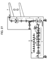
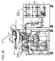
- Figs. 27 and 28 are side views of a copying machine (an image forming device) according to an embodiment of the present invention.
- the copying machine includes a main body 200.
- Reference numeral 1 denotes a paper sheet folding device connected to the rear surface of the main body 200.
- the paper sheet folding device 1 comprises a connecting section 2 for connecting the paper sheet folding device 1 to the main body 200; an edge-face folding section 3 that folds the edge face of a paper sheet tip; an accordion-folding section 4 that accordion-folds a paper sheet in the delivery direction; a delivery switching section 5 that switches the accordion-folded paper sheet in the delivery direction; a cross-folding section 6 that cross-folds the switched paper sheet in the delivery direction; a reversing section 7 that reverses the paper sheet folded into A4 size in the cross-folding section 6; a rotating section 8 that rotates the paper sheet; and a tray 9 that the paper sheet is discharged thereto.
- the main body 200 includes an image reader 205 and a manual paper feeding tray 208 arranged under the image reader 205.
- the paper sheet is fed into the main body 200 and paused by a regist roller 207 and then fed into an image forming unit 206 at an appropriate timing.
- the image forming unit 206 forms a latent image corresponding to image data on a photoreceptor, the latent image is developed with toner, and the toner is fixed on the paper sheet by a fixing device 210.
- the paper sheet is then discharged by a paper sheet discharging roll 211 from the copying machine and fed into the paper sheet folding device 1 when the paper sheet is to be folded.
- the paper sheet is fed into the middle part of the main body 200 by an upper paper sheet discharging roller 209 with a switching claw (not shown).
- the edge-face folding section 3 folds an edge face of the paper sheet delivered into the paper sheet folding device 1.
- the paper sheet is further accordion-folded in the delivery direction by the accordion-folding section 4 and delivered to the delivery switching section 5.
- the accordion-folded paper sheet delivered to the delivery switching section 5 is subjected to skew correction in a direction indicated by arrow A in Fig. 28 and punched if the paper sheet is to be punched, and then delivered to the cross-folding section 6.
- the accordion-folded paper sheet delivered to the cross-folding section 6 is further accordion-folded to be in A4 size in a direction perpendicular to the first accordion-folded direction.
- the paper sheet folded in A4 size is reversed by the reversing section 7 to be face-down and rotated to the left and right by 90 degrees to be aligned in the same direction by the rotating section 8 and then discharged to the tray 9.
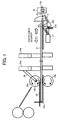
- Fig. 1 is a side view and Fig. 2 is an plan view of the delivery switching section 5.
- Fig. 3 is an enlarged side view of the delivery switching section 5.
- a paper sheet P in Fig. 3 is in the state where the edge face of paper sheet has been folded in the edge-face folding section 3, and the paper sheet is further accordion-folded in the delivery direction in the accordion-folding section 4.
- Inlet delivery rollers 20 rotate in directions indicated by respective arrows.
- the side of the paper sheet contacts a drop guide plate 29 whereby the paper sheet is dropped into a jogger fence 22.
- a jogger fence 22a in the upstream side is located under the inlet delivery rollers 20 on standby.
- a jogger motor 39 rotates clockwise, a drive belt 37 that is coupled to the jogger fence 22a and a jogger fence 22b rotates in a direction indicated by arrows via a jogger motor pulley 39a, a drive belt 40, and a pulley 38, so that the jogger fences 22a, 22b are closed.
- a jogger fence home position light shielding plate 22e fixed to the jogger fence 22a is in a standby position
- the jogger fence home position light shielding plate 22e shields a jogger fence home position sensor 28 against the light so that the jogger fence home position sensor 28 turns ON.
- the jogger fences 22a, 22b move, the jogger fence home position sensor 28 turns OFF.
- the moving distance of jogger fences 22a, 22b is determined based on the driving time of the jogger motor 39.
- each of the jogger fences 22a and 22b moves for the same distance.
- the distances between each of the jogger fences 22a, 22b and the delivery center of the cross-folding section 6 in the downstream side are equal.
- the distances between the jogger fences 22a, 22b and the delivery center of the rotation section 8 are equal.
- the center line of a paper sheet P is always set on a prespecified position regardless of the size of the paper sheet P.
- the jogger fence 22b in the downstream side is rotatable around a rotation center 22c, and a long hole 22d of the jogger fence 22b is coupled to a jogger fence oscillating solenoid 27.
- a jogger fence oscillating solenoid 27 turns ON, the jogger fence 22b rotates around the rotation center 22c and escapes from the paper sheet delivery path (See Fig. 1).
- the paper sheet delivered to the jogger fences 22a, 22b can be delivered in either a vertical direction or a lateral direction both in the upstream side and in the downstream side by return rollers 23.
- a plurality of the return rollers 23 are provided for stable delivery of the paper sheet P even though the type of folding and the size of a paper sheet are different such as an A1-sized paper sheet in Fig. 10 or an A4-sized paper sheet in Fig. 13.
- the return rollers 23 are disposed facing to a punching section (hole positions) in a lateral hole punching unit 10 to prevent skewing of the paper sheet when delivering to the punching section and provide a stable punching.
- the return rollers 23 are also disposed adjacent to the jogger fence 22a in the upstream side.
- a pulley 34 secured on the same shaft with drive return rollers 23b is connected to a drive belt 35, a pulley 32, a drive belt 31, and a vertical delivery motor pulley 30a.
- a vertical delivery motor 30 shown in Fig. 15 rotates counterclockwise
- the drive return rollers 23b also rotate counterclockwise.
- the drive return rollers 23b also rotate clockwise.
- a pulley 33 secured on the same shaft with the inlet delivery roller 20 is connected to the drive belt 35, the pulley 32, the drive belt 31, and the vertical delivery motor pulley 30a.
- the pulley 33 also rotates counterclockwise so that the paper sheet is delivered and dropped into the jogger fence 22.
- a pressing guide 25 is rotatably attached on the same shaft with a rotation fulcrum shaft 23c of the pressure driven return roller 23a. As shown Fig. 5, when the pressure driven return roller 23a contacts the paper sheet P, the pressing guide 25 presses the top surface of the paper sheet.
- the paper sheet delivered to the jogger fences 22a, 22b may be delivered to the cross-folding section 6 in the downstream side by a lateral delivery roller 24.
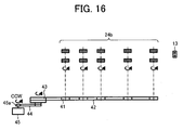
- a pulley 41 secured on the same shaft with lateral delivery drive rollers 24b is connected to a drive belt 42, a pulley 43, a drive belt 44, and a lateral delivery motor pulley 45a.
- a lateral delivery motor 45 rotates counterclockwise, the lateral delivery drive rollers 24b are driven to rotate counterclockwise so that the paper sheet is delivered to the cross-folding section 6.
- a pressure driven lateral delivery roller 24a is, as shown in Fig. 18, connected to a lateral delivery oscillating pressure bracket 50 via a shaft 24c of the pressure driven lateral delivery roller 24a and a spring 51.
- the lateral delivery oscillating pressure bracket 50 supporting a line of a plurality of the pressure driven lateral delivery rollers 24a rotates and oscillates from a position indicated by the dashed-two dotted line that is a standby position to a position indicated by the solid line around a rotation center 50a.
- the lateral delivery oscillating pressure bracket 50 is rotatably connected to a lateral delivery oscillating pressure arm 53 at a lateral delivery oscillating pressure arm connecting fulcrum 50b, and the lateral delivery oscillating pressure arm 53 is rotatably connected to a lateral delivery oscillating lever 54 coupled to a pulley 55 at a lateral delivery oscillating pressure lever connecting fulcrum 53a.
- the pulley 55 is connected to a pulley 57a of a lateral delivery oscillating pressure motor 57 via a drive belt 56.
- the lateral delivery oscillating pressure motor 57 rotates clockwise, the pressure driven lateral delivery rollers 24a move from a position indicated by the solid line where the lateral delivery drive rollers 24b contact to a position indicated by the dashed-two dotted line that is a standby position.
- the pressure driven lateral delivery rollers 24a move from a position indicated by the dashed-two dotted line that is a standby position to a position indicated by the solid line where the lateral delivery drive rollers 24b contact.
- the lateral delivery oscillating pressure arm 53 includes a home position detecting light shielding plate 50c and detects a position with a home position sensor 52 at the position indicated by the dashed-two dotted line, namely at the standby position of the pressure driven lateral delivery rollers 24a.
- the lateral hole punching unit 10 includes, as shown in Fig. 19, a clutch for lateral hole punching 60 on the same shaft with a drive shaft 10a of the lateral hole punching unit that punches by moving up and down, and holds a home position light shielding plate for lateral hole punching 62 on the same shaft.
- the clutch for lateral hole punching 60 is connected to a motor for lateral hole punching 63, and the home position light shielding plate for lateral hole punching 62 shields a home position sensor for lateral hole punching 61 against the light at the standby position and then the home position sensor for lateral hole punching 61 turns ON.
- the clutch for lateral hole punching 60 turns ON and the drive shaft 10a of the lateral hole punching unit rotates, so that the lateral hole punching unit 10 starts punching by moving up and down.
- the drive shaft 10a of the lateral hole punching unit rotates by 360 degrees
- the home position light shielding plate for lateral hole punching 62 shields the home position sensor for lateral hole punching 61 against the light
- the home position sensor for lateral hole punching 61 turns ON
- the clutch for lateral hole punching 60 turns OFF
- the home position light shielding plate for lateral hole punching 62 stops at the standby position.
- a paper sheet tip detecting sensor for lateral hole punching 12 is disposed adjacent to the entrance of lateral hole punching unit 10 and detects a timing to stop delivering a paper sheet to the lateral hole punching unit 10.
- the vertical hole punching unit 11 includes a clutch for vertical hole punching 64 on the same shaft with a drive shaft 11a of the vertical hole punching unit that punches by moving up and down, and holds a home position light shielding plate for vertical hole punching 66 on the same shaft.
- the clutch for vertical hole punching 64 is connected to a motor for vertical hole punching 67, and the home position light shielding plate for vertical hole punching 66 shields a home position sensor for vertical hole punching 65 against the light at the standby position and then the home position sensor for vertical hole punching 65 turns ON.
- the clutch for vertical hole punching 64 turns ON and the drive shaft 11a of the vertical hole punching unit rotates, so that the vertical hole punching unit 11 starts punching by moving up and down.
- the drive shaft 11a of the vertical hole punching unit rotates by 360 degrees, the home position light shielding plate for vertical hole punching 66 shields the home position sensor for vertical hole punching 65 against the light, the home position sensor for vertical hole punching 65 turns ON, the clutch for vertical hole punching 64 turns OFF, and then the home position light shielding plate for vertical hole punching 66 stops at the standby position.
- a paper sheet tip detecting sensor for vertical hole punching 13 is disposed adjacent to the entrance of vertical hole punching unit 11 and detects a timing to stop delivering a paper sheet to the vertical hole punching unit 11.
- the vertical hole punching unit 11 is inclined. It is easy to collect paper chips or paper dust produced during the punching that drops into a vertical hole punching chip tray 11c.
- a main body controlling substrate 202 When a main body controlling substrate 202 receives input signals such as the type of folding and the size of paper sheet from an operating section 201 of the main body, information is transmitted to a cross controlling substrate and then a paper sheet is delivered and punched by controlling each motor based on the information transmitted from each sensor.
- step S1 when the vertical delivery motor 30 in Fig. 15 rotates counterclockwise, a paper sheet is delivered into the inlet delivery roller 20 and further delivered along a guide plate 29 in Fig. 3, and then dropped into the jogger fence 22 (step S1).
- the paper sheet P is detected whether a deckle edge of the paper sheet is folded (step S2).
- a flow for measuring the delivery time of the paper sheet is executed as shown in a flowchart of Fig. 22A (steps S3 and S4).
- an inlet sensor for deckle edge folding 21b detects a tip of the paper sheet.
- an inlet sensor for deckle edge folding 21a detects a tip of the paper sheet.
- step S101 For measuring the delivery time of the paper sheet, when the inlet sensor for deckle edge 21a or the inlet sensor for deckle edge 21b turns ON after the paper sheet P is delivered from the accordion-folding section 4 (step S101), the delivery time of the paper sheet a is counted by a delivery switching punch controller 100 (step S102), and then the inlet sensor 21a or the inlet sensor 21b turns OFF (step S103) and the measurement of the delivery time of the paper sheet is completed.
- the paper sheet P is delivered in a direction indicated by an arrow and dropped into the jogger fence 22, and after a prespecified period of time, the vertical delivery motor 30 stops (step S5).
- the delivery switching punch controller 100 calculates moving distance of the jogger fence ß.
- the moving distance of the jogger fence ß is calculated on expressions shown in steps S402 (*2) and S403 (*1) as shown in a flowchart of Fig. 23A.
- Clearances A in Fig. 3 are clearances between a paper sheet and the jogger fence 22a in the upstream side, the jogger fence 22b in the downstream side respectively.
- the paper sheet is dropped in a position close to the jogger fence 22a in the upstream side based on the angle and the height of the guide plate 29, and the discharging velocity of the paper sheet P from the inlet delivery rollers 20.
- the clearance A between the paper sheet and the jogger fence 22a in the upstream side in Fig. 3 is set to zero.
- step S8 When the jogger motor 39 in Fig. 15 rotates clockwise (step S8), the jogger fence 22 is moved by the moving distance of the jogger fence ß calculated in S6 and the jogger motor 39 stops with leaving the clearance A as shown in Fig. 3 (step S9).
- the flow action skips to the lateral delivery movement (step S15).
- skew correction such that the paper sheet is struck to the jogger fence 22a by the drive return rollers 23a, 23b in Fig. 5 is executed.
- the paper sheet P is checked to determine whether the paper sheet P is a portrait A4-sized paper sheet, a landscape A4-sized paper sheet, or a portrait A3-sized paper sheet.
- the solenoid 49 in Fig. 17 turns ON.
- the vertical delivery arm 26 rotates from a position indicated by the dashed-two dotted line to a position indicated by the solid line around the supporting point 26a of the vertical delivery arm 26, and the pressure driven return roller 23a attached to the vertical delivery arm 26 via the pressure spring 46 contacts and pressurizes the drive return roller 23b (step S11).
- the state is shown in Fig. 5.
- the pressing guide 25 rotatably attached on the same shaft with the rotation fulcrum shaft 23c of the pressure driven return roller 23a presses the top surface of the paper sheet.
- the vertical delivery motor 30 in Fig. 15 rotates clockwise, the paper sheet P is delivered to the jogger fence 22a in the upstream side by the drive return roller 23b in Fig. 5 (step S12).
- step S13 when the paper sheet P is delivered from a position indicated by the solid line to a position indicated by the dashed line where the paper sheet P contacts the jogger fence 22a in the upstream side, after a prespecified period of time, the vertical delivery motor 30 stops (step S13).
- the solenoid 49 turns OFF, as shown in Fig. 17, the pressure driven return roller 23a moves away from the drive return roller 23b and rotates from a position indicated by the solid line to a position indicated by the dashed-two dotted line that is the standby position (step S14).
- the lateral delivery oscillating pressure motor 57 stops (step S16).
- the lateral delivery motor 45 rotates counterclockwise as shown in Fig. 16
- the lateral delivery drive rollers 24b are driven to rotate in a direction indicated by arrows.
- the pressure driven lateral delivery rollers 24a press and sandwich the paper sheet P with the lateral delivery drive rollers 24b, and the lateral delivery drive rollers 24b rotate in directions indicated by arrows and deliver the paper sheet P in a lateral direction towards the cross-folding section 6 as shown in Fig. 13 (step S17).
- the paper sheet P is checked to determine whether the paper sheet is to be punched (step S18).
- checking is performed to determine whether the required punching is the vertical hole punching or the lateral hole punching (step S19).
- a paper sheet moving process for vertical hole punching position is executed (step S20).
- a paper sheet moving process for lateral hole punching position is executed (step S21).
- the paper sheet P is delivered in a lateral direction to the cross-folding section 6.
- a tip of the paper sheet P passes through the paper sheet tip detecting sensor for vertical hole punching 13 (step S22), and then a rear end of the paper sheet P passes through the paper sheet tip detecting sensor for vertical hole punching 13 (step S23).
- the lateral delivery motor 45 stops (step S24). Then a jogger fence home position moving process (See Fig. 22B) and a lateral delivery oscillating pressure home position moving process (See Fig. 22C) are executed, and then the processing flow is completed.
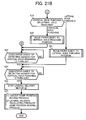
- the jogger fence home position moving process is a process that the jogger fence 22 is returned back to the standby position, namely, to a position where the jogger fence home position light shielding plate 22e shields the jogger fence home position sensor 28 against the light and the jogger fence home position sensor 28 turns ON.
- the jogger motor 39 rotates counterclockwise as shown in Fig. 15 (step S201)
- the jogger fences 22a, 22b move in the open direction
- the jogger fence home position light shielding plate 22e shields the jogger fence home position sensor 28 against the light and the jogger fence home position sensor 28 turns ON (step S202).
- the jogger fence home position sensor 28 turns ON, the jogger motor 39 stops (step S203), and then the jogger fence home position moving process is completed.
- FIG. 22C A flowchart for the lateral delivery oscillating pressure home position moving process in Fig. 22C is described.
- the lateral delivery oscillating pressure motor 57 rotates clockwise (step S301)
- the pressure driven lateral delivery rollers 24a move away from a position indicated by the solid line that contact to the lateral delivery drive rollers 24b to a position indicated by the dashed-two dotted line that is the standby position (step S301).
- the home position detecting light shielding plate 50c for the lateral delivery oscillating pressure arm 53 makes the home position sensor 52 turn ON (step S302), and the home position sensor 52 detects a standby position.
- the lateral delivery oscillating pressure motor 57 stops (step S303), and then the lateral delivery oscillating pressure home position moving process is completed.
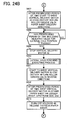
- a flowchart for the paper sheet moving process for vertical hole punching position (step S20) in Fig. 21 is described with reference to a flowchart in Fig. 23B.
- a delivery switching claw solenoid 15 in Fig. 8 turns ON
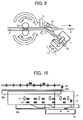
- a punch delivery switching claw 14 in Fig. 9 moves from a position indicated by the dashed lied to a position indicated by the solid line, and the paper sheet delivery path is turned into the vertical hole punching unit 11 (step S501).
- the paper sheet tip detecting sensor for vertical hole punching 13 detects an ON signal (step S502), and the lateral delivery motor 45 in Fig.
- the prespecified period of time for stopping the lateral delivery motor 45 is the total of a period of time for delivering the paper sheet P to a prespecified position to be punched and a period of time for adjusting the vertical hole position as shown in Fig. 8.
- the correction value L for the vertical hole punching position is zero, a tip of the paper sheet contacts to a vertical hole punching struck surface 11b.
- step S506 When the lateral delivery motor 45 stops, a vertical hole punching executing process is made (step S506).
- the lateral delivery motor 45 rotates clockwise, the lateral delivery drive rollers 24b are driven to rotate in the reverse direction and switchback the delivery direction of the paper sheet P indicated by dashed line arrows in Fig. 9 (step S507).
- step S508 When a tip of the paper sheet P passes through the paper sheet tip detecting sensor for vertical hole punching 13 (step S508), the lateral delivery motor 45 stops and the delivery switching claw solenoid 15 in Fig. 8 turns OFF, and then the switchback delivery is stopped (step S509).
- the lateral delivery drive rollers 24b are driven to rotate counterclockwise, and the pressure driven lateral delivery rollers 24a press and sandwich the paper sheet P with the lateral delivery drive rollers 24b.
- the pressure driven lateral delivery rollers 24a and the lateral delivery drive rollers 24b rotate in the directions indicated by arrows as shown in Fig. 16, and the paper sheet P is delivered in a lateral direction to the cross-folding section 6 (step S510), and then the paper sheet moving process for vertical hole punching position is completed.
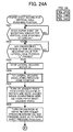
- a flowchart for the paper sheet moving process for lateral hole punching position (step S21) in Fig. 21 is described with reference to a flowchart in Fig. 24.
- the paper sheet tip detecting sensor for vertical hole punching 13 detects an ON signal (step S602) and the lateral delivery motor 45 stops in a prespecified period of time (step S603).
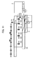
- the prespecified period of time in this case is the total of a period of time for delivering the paper sheet P to a prespecified position to be punched and a period of time for adjusting the lateral hole position as shown Fig. 11.
- a paper sheet moving process for lateral delivery oscillating pressure home position is executed (step S604).
- the jogger fence oscillating solenoid 27 turns ON, the jogger fence 22b rotates around the rotation center 22c and moves from a position indicated by the dashed line that is out of the paper sheet delivery path to a position indicated by the solid line as shown in Fig. 1 (step S605).
- the solenoid 49 in Fig. 17 turns ON, the vertical delivery arm 26 rotates and moves from a position indicated by the dashed-two dotted line to a position indicated by the solid line, and the pressure driven return roller 23a contacts to the drive return roller 23b.
- the state is as shown in Fig. 1 (step S606).
- step S607 After a prespecified period of time, when the vertical delivery motor 30 rotates counterclockwise, the drive return roller 23b in Fig. 1 rotates in a direction of an arrow indicated by the solid line, and the paper sheet P is delivered in a direction of an arrow indicated by the solid line (step S607).
- step S608 When a tip of the paper sheet P passes through the paper sheet tip detecting sensor for lateral hole punching 12 (step S608), the vertical delivery motor 30 stops after a prespecified period of time (step S609).
- the prespecified period of time in this case is the total of a period of time for delivering the paper sheet P to a prespecified position to be punched and a period of time for adjusting the lateral hole position as shown Fig. 11.
- the correction value L for the lateral hole punching position is zero, a tip of the paper sheet contacts to a lateral hole punching struck surface 10b.
- the lateral hole punching unit 10 has an opening with a width enough to insert a paper sheet therein such that the length of binding margin h of the paper sheet P in Fig. 12 is more than the width of binding margin W.
- the return rollers 23 are disposed in a position facing to a punching position of the lateral hole punching unit 10 as shown in Fig. 11. In this state, the lateral hole punching executing process is executed and then lateral hole punching is done (step S610).
- step S611 When the vertical delivery motor 30 in Fig. 15 rotates clockwise, the drive return roller 23b in Fig. 1 rotates in a direction indicated by a dashed line arrow so that the delivery direction is switchback and the paper sheet P is delivered in a direction indicated by a dashed line arrow towards the jogger fence 22a in the upstream side (step S611). After a prespecified period of time, the paper sheet P is struck to the jogger fence 22a in the upstream side and the vertical delivery motor 30 stops (step S612).
- step S613 When the solenoid 49 in Fig. 17 turns OFF, the pressure driven return roller 23a moves away from the drive return roller 23b, and the vertical delivery arm 26 rotates and returns back from a position indicated by the solid line to a position indicated by the dashed-two dotted line that is the standby position (step S613).
- the jogger fence oscillating solenoid 27 in Fig. 1 turns OFF, the jogger fence 22b rotates around the rotation center 22c and moves from a position indicated by the solid line that guides the paper sheet P to a position indicated by the dashed line (step S614).
- the pressure driven lateral delivery rollers 24a move from a position indicated by the dashed-two dotted line that is the standby position to a position indicated by the solid line that contact with the lateral delivery drive rollers 24b (step S615). After a prespecified period of time, the pressure driven lateral delivery rollers 24a move to a position indicated by the dashed line with sandwiching the paper sheet P with the lateral delivery drive rollers 24b, and the lateral delivery oscillating pressure motor 57 stops (step S616).
- step S617 When the lateral delivery motor 45 rotates counterclockwise once again, the paper sheet P in Fig. 11 is delivered towards the cross-folding section 6 (a direction indicated by an arrow) (step S617). After a tip of the paper sheet P is confirmed to be on the paper sheet tip detecting sensor for vertical hole punching 13 (step S618), a rear end of the paper sheet P passes through the paper sheet tip detecting sensor for vertical hole punching 13 (step S619). After the rear end of the paper sheet P passes through the paper sheet tip detecting sensor for vertical hole punching 13, the lateral delivery motor 45 stops (step S620), and the jogger fence home position moving process and the lateral delivery oscillating pressure home position moving process are executed (step S621), and then the flows are completed.
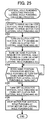
- the vertical/lateral hole punching executing processes in S506, S610 are described with reference to a flowchart in Fig. 25.
- the vertical hole punching unit 11 and the lateral hole punching unit 10 have basically same configuration so that only the vertical hole punching unit 11 is described.
- the motor for vertical hole punching 67 in Fig. 19 rotates in a prespecified direction (step S701)
- the clutch for vertical hole punching 64 turns ON (step S702).
- the home position sensor for vertical hole punching 65 is confirmed to be ON-state that is a standby-state.
- the rotation drive of the motor for vertical hole punching 67 is transmitted via the clutch for vertical hole punching 64 to the drive shaft 11a of vertical hole punching, and a mechanism of the punching (not shown) executes punching.
- the home position sensor for vertical hole punching 65 is switched OFF.
- the home position sensor for vertical hole punching 65 is switched ON to be the standby-state again (step S704).
- the clutch for vertical hole punching 64 turns OFF (step S705), and the motor for vertical hole punching 67 stops in a prespecified period of time, and then the flow of the paper sheet moving process for vertical hole punching is completed.
- the flow of the paper sheet moving process for lateral hole punching is same as the flow of the paper sheet moving process for vertical hole punching.
- the paper sheet with binding holes formed thereon is switchback in the reverse direction, so that the paper sheet need not pass through the lateral hole punching unit 10 and the vertical hole punching unit 11.
- it is unnecessary to provide a wide clearance between the punch and the die in the punching unit so that it may avoid the problem in punching due to the irregular clearances.
- skew correction to the paper sheet is executed.
- the paper sheet is inserted straightforward into the punching units 10, 11 so that it may improve the punching accuracy.
- Skew correction to the folded paper sheet before punched thereon is done by the jogger fence 20, namely skew correction only for punching is not required. Thus, it may reduce costs.
- the punching units 10, 11 include a punching struck surface in the downstream side of the delivery direction respectively so that a distance between a tip of the paper sheet and the punching position is maintained constant. Thus, it may minimize the irregularity of punching positions.
- the vertical hole punching unit 11 is inclined against the delivery direction so that a punching chip drops into a punching chip tray with its own weight. It is unnecessary to provide a mechanism for collecting a punching chip in the vertical hole punching unit 11, so that it may reduce costs.
- the width of the lateral hole punching unit 10 for paper sheet entry is larger than the width of binding margin so that the binding margin of the paper sheet is hardly stuck in the entrance of the lateral hole punching unit 10. Thus, it may avoid the paper jam.
- the present invention is not limited to the embodiments described above and various changes may be made without departing from the scope of the invention. According to the embodiments described above, the vertical hole punching unit 11 is inclined against the delivery direction. Alternatively, the lateral hole punching unit 10 may be inclined against the delivery direction.
- the paper sheet is switchback in the reverse direction, so that the paper sheet need not pass through a punching unit.
Landscapes
- Engineering & Computer Science (AREA)
- Mechanical Engineering (AREA)
- Life Sciences & Earth Sciences (AREA)
- Forests & Forestry (AREA)
- Physics & Mathematics (AREA)
- General Physics & Mathematics (AREA)
- Folding Of Thin Sheet-Like Materials, Special Discharging Devices, And Others (AREA)
- Paper Feeding For Electrophotography (AREA)
- Separation, Sorting, Adjustment, Or Bending Of Sheets To Be Conveyed (AREA)
- Registering Or Overturning Sheets (AREA)
- Perforating, Stamping-Out Or Severing By Means Other Than Cutting (AREA)
Abstract
Description
- The present document incorporates by reference the entire contents of
Japanese priority document, 2005-223684 filed in Japan on August 2, 2005 - The present invention relates to a paper-sheet punching device that punches a hole in a paper sheet.
-
Japanese Patent Laid-Open Publication No. S62-32798 - In the conventional punching device, thus, it is necessary to secure a nip having a sufficient width between the punch and the die in consideration of the thickness of the paper sheet so that a stroke of the punch becomes longer. A longer stroke has a greater chance of punching irregular holes than a shorter stroke.
- It is an object of the present invention to at least partially solve the problems in the conventional technology.
- According to an aspect of the present invention, a paper-sheet punching device punches a hole in a paper sheet and includes a punching unit that receives a paper sheet from a first arrangement via an inlet, and punches a hole in the paper sheet; and a switchback delivery unit that delivers the paper sheet with the hole to a second arrangement via an outlet.
- According to another aspect of the present invention, a paper-sheet folding device that folds a paper sheet includes the above paper sheet punching device.
- According to still another aspect of the present invention, an image forming device that forms an image on a paper sheet based on an electrostatic latent image read from an original includes the above paper sheet punching device.
- The above and other objects, features, advantages and technical and industrial significance of this invention will be better understood by reading the following detailed description of presently preferred embodiments of the invention, when considered in connection with the accompanying drawings.
-
- Fig. 1 is a side view of a delivery switching device according to an embodiment of the present invention;
- Fig. 2 is a plan view of the delivery switching device shown in Fig. 1;
- Fig. 3 is an enlarged side view of the delivery switching device shown in Fig. 1;
- Fig. 4 is a plan view of the delivery switching device for explaining skew correction performed to a portrait A1-sized paper sheet in the switching device;
- Fig. 5 is a side view of the delivery switching device for explaining the skew correction performed to a portrait A1-sized paper sheet in the switching device;
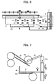
- Fig. 6 is a plan view of the delivery switching device for explaining the skew correction performed to a portrait A1-sized paper sheet in the switching device;
- Fig. 7 is a side view of the delivery switching device for explaining the skew correction performed to a portrait A1-sized paper sheet in the switching device;
- Fig. 8 is a plan view of the delivery switching device for explaining punching of a landscape A2-sized paper sheet;
- Fig. 9 is an enlarged side view of a punching device shown in Fig. 2;
- Fig. 10 is a plan view of the delivery switching device in a state before punching a portrait A1-sized paper sheet;
- Fig. 11 is a plan view of the delivery switching device in a state while punching the portrait A1-sized paper sheet;
- Fig. 12 is a perspective view of a folded portrait A1-sized paper sheet;
- Fig. 13 is a plan view of the delivery switching device for explaining skew correction performed to a landscape A4-sized paper sheet;
- Fig. 14 is a side view of the delivery switching device for explaining skew correction performed to a landscape A4-sized paper sheet;
- Fig. 15 is a plan view for explaining drive configuration of jogger fences, inlet delivery rollers, and return rollers in the delivery switching device;
- Fig. 16 is a plan view for explaining drive configuration of lateral delivery rollers in the delivery switching device;
- Fig. 17 is a schematic view for explaining an oscillating mechanism of a return roller in the delivery switching device;
- Fig. 18 is a schematic view for explaining a pressure oscillating mechanism of the lateral delivery rollers in the delivery switching device;
- Fig. 19 is a schematic block diagram for explaining a punching mechanism of the delivery switching device;
- Fig. 20 is a flowchart for explaining skew correction to a paper sheet according to the present embodiments;
- Fig. 21 is a continuation of the flowchart shown in Fig. 20;
- Fig. 22A is a flowchart for explaining measurement of the delivery time of a paper sheet;
- Fig. 22B is a flowchart for explaining the movement of a jogger fence home position;
- Fig. 22C is a flowchart for explaining the movement of a lateral delivery oscillating pressure home position;
- Fig. 23A is a flowchart for explaining calculation of the moving distance of a jogger;
- Fig. 23B is a flowchart for explaining movement of a paper sheet to a lateral hole punching position;
- Fig. 24 is a flowchart for explaining the movement of a paper sheet for the position of a lateral hole punching position;
- Fig. 25 is a flowchart for explaining a working process of lateral hole punching;
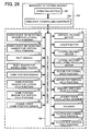
- Fig. 26 is a block diagram of the paper sheet folding device according to the embodiments;
- Fig. 27 is a side view of the paper sheet folding device according to the embodiments; and
- Fig. 28 is a side view of a copying machine with the paper sheet folding device.
- Exemplary embodiments according to the present invention are described below with reference to the accompanying drawings.
- Figs. 27 and 28 are side views of a copying machine (an image forming device) according to an embodiment of the present invention. The copying machine includes a
main body 200.Reference numeral 1 denotes a paper sheet folding device connected to the rear surface of themain body 200. The papersheet folding device 1 comprises a connectingsection 2 for connecting the papersheet folding device 1 to themain body 200; an edge-face folding section 3 that folds the edge face of a paper sheet tip; an accordion-folding section 4 that accordion-folds a paper sheet in the delivery direction; adelivery switching section 5 that switches the accordion-folded paper sheet in the delivery direction; across-folding section 6 that cross-folds the switched paper sheet in the delivery direction; a reversing section 7 that reverses the paper sheet folded into A4 size in thecross-folding section 6; a rotatingsection 8 that rotates the paper sheet; and atray 9 that the paper sheet is discharged thereto. - The
main body 200 includes animage reader 205 and a manualpaper feeding tray 208 arranged under theimage reader 205. When a paper sheet is set on the manualpaper feeding tray 208, the paper sheet is fed into themain body 200 and paused by aregist roller 207 and then fed into animage forming unit 206 at an appropriate timing. - The
image forming unit 206 forms a latent image corresponding to image data on a photoreceptor, the latent image is developed with toner, and the toner is fixed on the paper sheet by afixing device 210. The paper sheet is then discharged by a papersheet discharging roll 211 from the copying machine and fed into the papersheet folding device 1 when the paper sheet is to be folded. When the paper sheet is not to be folded, the paper sheet is fed into the middle part of themain body 200 by an upper papersheet discharging roller 209 with a switching claw (not shown). - The edge-
face folding section 3 folds an edge face of the paper sheet delivered into the papersheet folding device 1. The paper sheet is further accordion-folded in the delivery direction by the accordion-folding section 4 and delivered to thedelivery switching section 5. The accordion-folded paper sheet delivered to thedelivery switching section 5 is subjected to skew correction in a direction indicated by arrow A in Fig. 28 and punched if the paper sheet is to be punched, and then delivered to thecross-folding section 6. - The accordion-folded paper sheet delivered to the
cross-folding section 6 is further accordion-folded to be in A4 size in a direction perpendicular to the first accordion-folded direction. The paper sheet folded in A4 size is reversed by the reversing section 7 to be face-down and rotated to the left and right by 90 degrees to be aligned in the same direction by therotating section 8 and then discharged to thetray 9. - Mechanism for performing skew correction according to the embodiment is described. Fig. 1 is a side view and Fig. 2 is an plan view of the
delivery switching section 5. Fig. 3 is an enlarged side view of thedelivery switching section 5. A paper sheet P in Fig. 3 is in the state where the edge face of paper sheet has been folded in the edge-face folding section 3, and the paper sheet is further accordion-folded in the delivery direction in the accordion-folding section 4.Inlet delivery rollers 20 rotate in directions indicated by respective arrows. At one time, the side of the paper sheet contacts adrop guide plate 29 whereby the paper sheet is dropped into ajogger fence 22. As shown in Fig. 3, ajogger fence 22a in the upstream side is located under theinlet delivery rollers 20 on standby. - As shown in Fig. 15, when a
jogger motor 39 rotates clockwise, a drive belt 37 that is coupled to thejogger fence 22a and ajogger fence 22b rotates in a direction indicated by arrows via ajogger motor pulley 39a, adrive belt 40, and apulley 38, so that thejogger fences light shielding plate 22e fixed to thejogger fence 22a is in a standby position, the jogger fence home positionlight shielding plate 22e shields a jogger fencehome position sensor 28 against the light so that the jogger fencehome position sensor 28 turns ON. When thejogger fences home position sensor 28 turns OFF. The moving distance ofjogger fences jogger motor 39. - As the
jogger motor 39 rotates, each of thejogger fences jogger fences cross-folding section 6 in the downstream side are equal. Furthermore, the distances between thejogger fences rotation section 8 are equal. Thus, the center line of a paper sheet P is always set on a prespecified position regardless of the size of the paper sheet P. - The
jogger fence 22b in the downstream side is rotatable around arotation center 22c, and along hole 22d of thejogger fence 22b is coupled to a joggerfence oscillating solenoid 27. When the joggerfence oscillating solenoid 27 turns ON, thejogger fence 22b rotates around therotation center 22c and escapes from the paper sheet delivery path (See Fig. 1). - The paper sheet delivered to the
jogger fences return rollers 23. A plurality of thereturn rollers 23 are provided for stable delivery of the paper sheet P even though the type of folding and the size of a paper sheet are different such as an A1-sized paper sheet in Fig. 10 or an A4-sized paper sheet in Fig. 13. As shown in Fig. 11, thereturn rollers 23 are disposed facing to a punching section (hole positions) in a lateralhole punching unit 10 to prevent skewing of the paper sheet when delivering to the punching section and provide a stable punching. - The
return rollers 23 are also disposed adjacent to thejogger fence 22a in the upstream side. Apulley 34 secured on the same shaft withdrive return rollers 23b is connected to adrive belt 35, apulley 32, adrive belt 31, and a verticaldelivery motor pulley 30a. When avertical delivery motor 30 shown in Fig. 15 rotates counterclockwise, thedrive return rollers 23b also rotate counterclockwise. - When the
vertical delivery motor 30 rotates clockwise, thedrive return rollers 23b also rotate clockwise. As shown in Fig. 15, apulley 33 secured on the same shaft with theinlet delivery roller 20 is connected to thedrive belt 35, thepulley 32, thedrive belt 31, and the verticaldelivery motor pulley 30a. When thevertical delivery motor 30 rotates counterclockwise, thepulley 33 also rotates counterclockwise so that the paper sheet is delivered and dropped into thejogger fence 22. - When the paper sheet P is delivered and dropped in the
jogger fence 22 by a pressure drivenreturn roller 23a as shown in Fig. 3, the pressure drivenreturn roller 23a moves away from thedrive return roller 23b and sets in a standby position to prevent from contacting the paper sheet. When thevertical delivery motor 30 and thedrive return roller 23b rotate and deliver the paper sheet as shown in Fig. 17, asolenoid 49 turns ON and pulls a verticaldelivery oscillating lever 47, avertical delivery arm 26 rotates from a position indicated by the dashed-two dotted line to a position indicated by the solid line around a supportingpoint 26a of thevertical delivery arm 26 so that the pressure drivenreturn roller 23a attached to thevertical delivery arm 26 via apressure spring 46 contacts and pressurizes thedrive return roller 23b. - When the
solenoid 49 turns OFF and the verticaldelivery oscillating lever 47 is released, thevertical delivery arm 26 rotates from the position indicated by the solid line to the position indicated by the dashed-two dotted line around the supportingpoint 26a of thevertical delivery arm 26 so that the pressure drivenreturn roller 23a attached to thevertical delivery arm 26 moves away from thedrive return roller 23b. As shown in Fig. 2 and Fig. 3, apressing guide 25 is rotatably attached on the same shaft with arotation fulcrum shaft 23c of the pressure drivenreturn roller 23a. As shown Fig. 5, when the pressure drivenreturn roller 23a contacts the paper sheet P, thepressing guide 25 presses the top surface of the paper sheet. - The paper sheet delivered to the
jogger fences cross-folding section 6 in the downstream side by alateral delivery roller 24. As shown in Fig. 16, apulley 41 secured on the same shaft with lateraldelivery drive rollers 24b is connected to adrive belt 42, apulley 43, adrive belt 44, and a lateraldelivery motor pulley 45a. When alateral delivery motor 45 rotates counterclockwise, the lateraldelivery drive rollers 24b are driven to rotate counterclockwise so that the paper sheet is delivered to thecross-folding section 6. - A pressure driven
lateral delivery roller 24a is, as shown in Fig. 18, connected to a lateral delivery oscillatingpressure bracket 50 via ashaft 24c of the pressure drivenlateral delivery roller 24a and a spring 51. The lateral delivery oscillatingpressure bracket 50 supporting a line of a plurality of the pressure drivenlateral delivery rollers 24a rotates and oscillates from a position indicated by the dashed-two dotted line that is a standby position to a position indicated by the solid line around arotation center 50a. - The lateral delivery oscillating
pressure bracket 50 is rotatably connected to a lateral delivery oscillatingpressure arm 53 at a lateral delivery oscillating pressurearm connecting fulcrum 50b, and the lateral delivery oscillatingpressure arm 53 is rotatably connected to a lateraldelivery oscillating lever 54 coupled to apulley 55 at a lateral delivery oscillating pressurelever connecting fulcrum 53a. - As shown in Fig. 18, the
pulley 55 is connected to a pulley 57a of a lateral delivery oscillatingpressure motor 57 via adrive belt 56. When the lateral delivery oscillatingpressure motor 57 rotates clockwise, the pressure drivenlateral delivery rollers 24a move from a position indicated by the solid line where the lateraldelivery drive rollers 24b contact to a position indicated by the dashed-two dotted line that is a standby position. When the lateral delivery oscillatingpressure motor 57 rotates counterclockwise, the pressure drivenlateral delivery rollers 24a move from a position indicated by the dashed-two dotted line that is a standby position to a position indicated by the solid line where the lateraldelivery drive rollers 24b contact. - The lateral delivery oscillating
pressure arm 53 includes a home position detectinglight shielding plate 50c and detects a position with ahome position sensor 52 at the position indicated by the dashed-two dotted line, namely at the standby position of the pressure drivenlateral delivery rollers 24a. - Configurations of the lateral hole punching unit (punching unit) 10 provided in parallel to the right downstream side of the
jogger fence 22b and the vertical hole punching unit (punching unit) 11 perpendicular to the lateral delivery direction are described below. The lateralhole punching unit 10 includes, as shown in Fig. 19, a clutch for lateral hole punching 60 on the same shaft with adrive shaft 10a of the lateral hole punching unit that punches by moving up and down, and holds a home position light shielding plate for lateral hole punching 62 on the same shaft. - The clutch for lateral hole punching 60 is connected to a motor for lateral hole punching 63, and the home position light shielding plate for lateral hole punching 62 shields a home position sensor for lateral hole punching 61 against the light at the standby position and then the home position sensor for lateral hole punching 61 turns ON. When the motor for lateral hole punching 63 starts rotating, the clutch for lateral hole punching 60 turns ON and the
drive shaft 10a of the lateral hole punching unit rotates, so that the lateralhole punching unit 10 starts punching by moving up and down. Thedrive shaft 10a of the lateral hole punching unit rotates by 360 degrees, the home position light shielding plate for lateral hole punching 62 shields the home position sensor for lateral hole punching 61 against the light, the home position sensor for lateral hole punching 61 turns ON, the clutch for lateral hole punching 60 turns OFF, and then the home position light shielding plate for lateral hole punching 62 stops at the standby position. - A paper sheet tip detecting sensor for lateral hole punching 12 is disposed adjacent to the entrance of lateral
hole punching unit 10 and detects a timing to stop delivering a paper sheet to the lateralhole punching unit 10. The verticalhole punching unit 11 includes a clutch for vertical hole punching 64 on the same shaft with adrive shaft 11a of the vertical hole punching unit that punches by moving up and down, and holds a home position light shielding plate for vertical hole punching 66 on the same shaft. - The clutch for vertical hole punching 64 is connected to a motor for vertical hole punching 67, and the home position light shielding plate for vertical hole punching 66 shields a home position sensor for vertical hole punching 65 against the light at the standby position and then the home position sensor for vertical hole punching 65 turns ON. When the motor for vertical hole punching 67 starts rotating, the clutch for vertical hole punching 64 turns ON and the
drive shaft 11a of the vertical hole punching unit rotates, so that the verticalhole punching unit 11 starts punching by moving up and down. Thedrive shaft 11a of the vertical hole punching unit rotates by 360 degrees, the home position light shielding plate for vertical hole punching 66 shields the home position sensor for vertical hole punching 65 against the light, the home position sensor for vertical hole punching 65 turns ON, the clutch for vertical hole punching 64 turns OFF, and then the home position light shielding plate for vertical hole punching 66 stops at the standby position. - A paper sheet tip detecting sensor for vertical hole punching 13 is disposed adjacent to the entrance of vertical
hole punching unit 11 and detects a timing to stop delivering a paper sheet to the verticalhole punching unit 11. - As shown in Fig. 9, the vertical
hole punching unit 11 is inclined. It is easy to collect paper chips or paper dust produced during the punching that drops into a vertical holepunching chip tray 11c. - When a main body controlling substrate 202 receives input signals such as the type of folding and the size of paper sheet from an
operating section 201 of the main body, information is transmitted to a cross controlling substrate and then a paper sheet is delivered and punched by controlling each motor based on the information transmitted from each sensor. - Functions and advantages of the paper sheet folding device are described below. With reference to Figs. 2 to 7, there is described the operation of skew correction to the paper sheet P that is folded its edge face in the edge-
face folding section 3 and further accordion-folded in the delivery direction in the accordion-folding section 4. - As shown in the flowchart of Fig. 20, when the
vertical delivery motor 30 in Fig. 15 rotates counterclockwise, a paper sheet is delivered into theinlet delivery roller 20 and further delivered along aguide plate 29 in Fig. 3, and then dropped into the jogger fence 22 (step S1). - For detecting the delivery time of the paper sheet P, the paper sheet P is detected whether a deckle edge of the paper sheet is folded (step S2). When the deckle edge of the paper sheet is folded, a flow for measuring the delivery time of the paper sheet is executed as shown in a flowchart of Fig. 22A (steps S3 and S4). When the deckle edge of the paper sheet is folded, an inlet sensor for
deckle edge folding 21b detects a tip of the paper sheet. When the deckle edge of the paper sheet is not folded, an inlet sensor fordeckle edge folding 21a detects a tip of the paper sheet. - For measuring the delivery time of the paper sheet, when the inlet sensor for
deckle edge 21a or the inlet sensor fordeckle edge 21b turns ON after the paper sheet P is delivered from the accordion-folding section 4 (step S101), the delivery time of the paper sheet a is counted by a delivery switching punch controller 100 (step S102), and then theinlet sensor 21a or theinlet sensor 21b turns OFF (step S103) and the measurement of the delivery time of the paper sheet is completed. - The paper sheet P is delivered in a direction indicated by an arrow and dropped into the
jogger fence 22, and after a prespecified period of time, thevertical delivery motor 30 stops (step S5). The deliveryswitching punch controller 100 calculates moving distance of the jogger fence ß. The moving distance of the jogger fence ß is calculated on expressions shown in steps S402 (*2) and S403 (*1) as shown in a flowchart of Fig. 23A. - (*1): [Distance between the jogger fences at the jogger home positions] minus [[delivery time of the paper sheet a] plus [clearance A]]
- (*2): [Distance between the jogger fences at the jogger home positions] minus [[delivery time of the paper sheet a] plus [clearance A]] plus [correction value L for the vertical hole punching position]
- Clearances A in Fig. 3 are clearances between a paper sheet and the
jogger fence 22a in the upstream side, thejogger fence 22b in the downstream side respectively. In the present example, when a paper sheet is delivered along theguide plate 29 and dropped into thejogger fence 22, the paper sheet is dropped in a position close to thejogger fence 22a in the upstream side based on the angle and the height of theguide plate 29, and the discharging velocity of the paper sheet P from theinlet delivery rollers 20. The clearance A between the paper sheet and thejogger fence 22a in the upstream side in Fig. 3 is set to zero. - When the
jogger motor 39 in Fig. 15 rotates clockwise (step S8), thejogger fence 22 is moved by the moving distance of the jogger fence ß calculated in S6 and thejogger motor 39 stops with leaving the clearance A as shown in Fig. 3 (step S9). - When the paper sheet P is not folded in the
cross-folding section 6 in the downstream side, in the example, when the paper sheet P in Fig. 2 is a portrait A4-sized paper sheet, a landscape A4-sized paper sheet, or a portrait A3-sized paper sheet, the flow action skips to the lateral delivery movement (step S15). When the paper sheet P is folded in thecross-folding section 6, skew correction such that the paper sheet is struck to thejogger fence 22a by thedrive return rollers - In the following step S10, the paper sheet P is checked to determine whether the paper sheet P is a portrait A4-sized paper sheet, a landscape A4-sized paper sheet, or a portrait A3-sized paper sheet. When the paper sheet P is not any of a portrait A4-sized paper sheet, a landscape A4-sized paper sheet, and a portrait A3-sized paper sheet, the
solenoid 49 in Fig. 17 turns ON. When thesolenoid 49 turns ON and pulls the verticaldelivery oscillating lever 47, thevertical delivery arm 26 rotates from a position indicated by the dashed-two dotted line to a position indicated by the solid line around the supportingpoint 26a of thevertical delivery arm 26, and the pressure drivenreturn roller 23a attached to thevertical delivery arm 26 via thepressure spring 46 contacts and pressurizes thedrive return roller 23b (step S11). - The state is shown in Fig. 5. The
pressing guide 25 rotatably attached on the same shaft with therotation fulcrum shaft 23c of the pressure drivenreturn roller 23a presses the top surface of the paper sheet. After a prespecified period of time, when thevertical delivery motor 30 in Fig. 15 rotates clockwise, the paper sheet P is delivered to thejogger fence 22a in the upstream side by thedrive return roller 23b in Fig. 5 (step S12). - As shown in Fig. 6, when the paper sheet P is delivered from a position indicated by the solid line to a position indicated by the dashed line where the paper sheet P contacts the
jogger fence 22a in the upstream side, after a prespecified period of time, thevertical delivery motor 30 stops (step S13). When thesolenoid 49 turns OFF, as shown in Fig. 17, the pressure drivenreturn roller 23a moves away from thedrive return roller 23b and rotates from a position indicated by the solid line to a position indicated by the dashed-two dotted line that is the standby position (step S14). - When the lateral delivery oscillating
pressure motor 57 in Fig. 18 rotates counterclockwise, the pressure drivenlateral delivery rollers 24a move from a position indicated by dashed-two dotted line that is the standby position to a position indicated by the solid line that contact to the lateraldelivery drive rollers 24b (step S15). - After a prespecified period of time, when the pressure driven
lateral delivery rollers 24a press and sandwich the paper sheet P with the lateraldelivery drive rollers 24b, the lateral delivery oscillatingpressure motor 57 stops (step S16). When thelateral delivery motor 45 rotates counterclockwise as shown in Fig. 16, the lateraldelivery drive rollers 24b are driven to rotate in a direction indicated by arrows. The pressure drivenlateral delivery rollers 24a press and sandwich the paper sheet P with the lateraldelivery drive rollers 24b, and the lateraldelivery drive rollers 24b rotate in directions indicated by arrows and deliver the paper sheet P in a lateral direction towards thecross-folding section 6 as shown in Fig. 13 (step S17). - The paper sheet P is checked to determine whether the paper sheet is to be punched (step S18). When the paper sheet P is to be punched, checking is performed to determine whether the required punching is the vertical hole punching or the lateral hole punching (step S19). When the vertical hole punching process is made on the paper sheet P, a paper sheet moving process for vertical hole punching position is executed (step S20). When the lateral hole punching process is made on the paper sheet P, a paper sheet moving process for lateral hole punching position is executed (step S21).
- When the punching process is not made on the paper sheet P or after the paper sheet moving process for vertical hole punching position (step S20), the paper sheet P is delivered in a lateral direction to the
cross-folding section 6. As shown in a position indicated by the dashed line in Fig. 6, a tip of the paper sheet P passes through the paper sheet tip detecting sensor for vertical hole punching 13 (step S22), and then a rear end of the paper sheet P passes through the paper sheet tip detecting sensor for vertical hole punching 13 (step S23). After the rear end of the paper sheet P passes through the paper sheet tip detecting sensor for vertical hole punching 13, thelateral delivery motor 45 stops (step S24). Then a jogger fence home position moving process (See Fig. 22B) and a lateral delivery oscillating pressure home position moving process (See Fig. 22C) are executed, and then the processing flow is completed. - A flowchart in Fig. 22B is described. The jogger fence home position moving process is a process that the
jogger fence 22 is returned back to the standby position, namely, to a position where the jogger fence home positionlight shielding plate 22e shields the jogger fencehome position sensor 28 against the light and the jogger fencehome position sensor 28 turns ON. When thejogger motor 39 rotates counterclockwise as shown in Fig. 15 (step S201), thejogger fences light shielding plate 22e shields the jogger fencehome position sensor 28 against the light and the jogger fencehome position sensor 28 turns ON (step S202). When the jogger fencehome position sensor 28 turns ON, thejogger motor 39 stops (step S203), and then the jogger fence home position moving process is completed. - A flowchart for the lateral delivery oscillating pressure home position moving process in Fig. 22C is described. As shown in Fig. 18, when the lateral delivery oscillating
pressure motor 57 rotates clockwise (step S301), the pressure drivenlateral delivery rollers 24a move away from a position indicated by the solid line that contact to the lateraldelivery drive rollers 24b to a position indicated by the dashed-two dotted line that is the standby position (step S301). The home position detectinglight shielding plate 50c for the lateral delivery oscillatingpressure arm 53 makes thehome position sensor 52 turn ON (step S302), and thehome position sensor 52 detects a standby position. When the standby position is detected, the lateral delivery oscillatingpressure motor 57 stops (step S303), and then the lateral delivery oscillating pressure home position moving process is completed. - A flowchart for the paper sheet moving process for vertical hole punching position (step S20) in Fig. 21 is described with reference to a flowchart in Fig. 23B. When a delivery switching
claw solenoid 15 in Fig. 8 turns ON, a punchdelivery switching claw 14 in Fig. 9 moves from a position indicated by the dashed lied to a position indicated by the solid line, and the paper sheet delivery path is turned into the vertical hole punching unit 11 (step S501). As shown in Fig. 8, when a tip of the paper sheet P passes through the paper sheet tip detecting sensor for vertical hole punching 13, the paper sheet tip detecting sensor for vertical hole punching 13 detects an ON signal (step S502), and thelateral delivery motor 45 in Fig. 16 stops (step S505) in a prespecified period of time (step S503). The prespecified period of time for stopping thelateral delivery motor 45 is the total of a period of time for delivering the paper sheet P to a prespecified position to be punched and a period of time for adjusting the vertical hole position as shown in Fig. 8. When the correction value L for the vertical hole punching position is zero, a tip of the paper sheet contacts to a vertical hole punching strucksurface 11b. - When the
lateral delivery motor 45 stops, a vertical hole punching executing process is made (step S506). When thelateral delivery motor 45 rotates clockwise, the lateraldelivery drive rollers 24b are driven to rotate in the reverse direction and switchback the delivery direction of the paper sheet P indicated by dashed line arrows in Fig. 9 (step S507). When a tip of the paper sheet P passes through the paper sheet tip detecting sensor for vertical hole punching 13 (step S508), thelateral delivery motor 45 stops and the delivery switchingclaw solenoid 15 in Fig. 8 turns OFF, and then the switchback delivery is stopped (step S509). - When the
lateral delivery motor 45 rotates counterclockwise once again as shown in Fig. 16, the lateraldelivery drive rollers 24b are driven to rotate counterclockwise, and the pressure drivenlateral delivery rollers 24a press and sandwich the paper sheet P with the lateraldelivery drive rollers 24b. The pressure drivenlateral delivery rollers 24a and the lateraldelivery drive rollers 24b rotate in the directions indicated by arrows as shown in Fig. 16, and the paper sheet P is delivered in a lateral direction to the cross-folding section 6 (step S510), and then the paper sheet moving process for vertical hole punching position is completed. - A flowchart for the paper sheet moving process for lateral hole punching position (step S21) in Fig. 21 is described with reference to a flowchart in Fig. 24. As shown in Fig. 10, when the paper sheet P is delivered in a lateral direction and a tip of the paper sheet P passes through the paper sheet tip detecting sensor for vertical hole punching 13, the paper sheet tip detecting sensor for vertical hole punching 13 detects an ON signal (step S602) and the
lateral delivery motor 45 stops in a prespecified period of time (step S603). The prespecified period of time in this case is the total of a period of time for delivering the paper sheet P to a prespecified position to be punched and a period of time for adjusting the lateral hole position as shown Fig. 11. - For switching from the lateral delivery to the vertical delivery of the paper sheet, a paper sheet moving process for lateral delivery oscillating pressure home position is executed (step S604). When the jogger
fence oscillating solenoid 27 turns ON, thejogger fence 22b rotates around therotation center 22c and moves from a position indicated by the dashed line that is out of the paper sheet delivery path to a position indicated by the solid line as shown in Fig. 1 (step S605). When thesolenoid 49 in Fig. 17 turns ON, thevertical delivery arm 26 rotates and moves from a position indicated by the dashed-two dotted line to a position indicated by the solid line, and the pressure drivenreturn roller 23a contacts to thedrive return roller 23b. The state is as shown in Fig. 1 (step S606). - After a prespecified period of time, when the
vertical delivery motor 30 rotates counterclockwise, thedrive return roller 23b in Fig. 1 rotates in a direction of an arrow indicated by the solid line, and the paper sheet P is delivered in a direction of an arrow indicated by the solid line (step S607). When a tip of the paper sheet P passes through the paper sheet tip detecting sensor for lateral hole punching 12 (step S608), thevertical delivery motor 30 stops after a prespecified period of time (step S609). - The prespecified period of time in this case is the total of a period of time for delivering the paper sheet P to a prespecified position to be punched and a period of time for adjusting the lateral hole position as shown Fig. 11. When the correction value L for the lateral hole punching position is zero, a tip of the paper sheet contacts to a lateral hole punching struck
surface 10b. - The lateral
hole punching unit 10 has an opening with a width enough to insert a paper sheet therein such that the length of binding margin h of the paper sheet P in Fig. 12 is more than the width of binding margin W. Thereturn rollers 23 are disposed in a position facing to a punching position of the lateralhole punching unit 10 as shown in Fig. 11. In this state, the lateral hole punching executing process is executed and then lateral hole punching is done (step S610). - When the
vertical delivery motor 30 in Fig. 15 rotates clockwise, thedrive return roller 23b in Fig. 1 rotates in a direction indicated by a dashed line arrow so that the delivery direction is switchback and the paper sheet P is delivered in a direction indicated by a dashed line arrow towards thejogger fence 22a in the upstream side (step S611). After a prespecified period of time, the paper sheet P is struck to thejogger fence 22a in the upstream side and thevertical delivery motor 30 stops (step S612). - When the
solenoid 49 in Fig. 17 turns OFF, the pressure drivenreturn roller 23a moves away from thedrive return roller 23b, and thevertical delivery arm 26 rotates and returns back from a position indicated by the solid line to a position indicated by the dashed-two dotted line that is the standby position (step S613). When the joggerfence oscillating solenoid 27 in Fig. 1 turns OFF, thejogger fence 22b rotates around therotation center 22c and moves from a position indicated by the solid line that guides the paper sheet P to a position indicated by the dashed line (step S614). - When the lateral delivery oscillating
pressure motor 57 rotates counterclockwise as shown in Fig. 18, the pressure drivenlateral delivery rollers 24a move from a position indicated by the dashed-two dotted line that is the standby position to a position indicated by the solid line that contact with the lateraldelivery drive rollers 24b (step S615). After a prespecified period of time, the pressure drivenlateral delivery rollers 24a move to a position indicated by the dashed line with sandwiching the paper sheet P with the lateraldelivery drive rollers 24b, and the lateral delivery oscillatingpressure motor 57 stops (step S616). - When the
lateral delivery motor 45 rotates counterclockwise once again, the paper sheet P in Fig. 11 is delivered towards the cross-folding section 6 (a direction indicated by an arrow) (step S617). After a tip of the paper sheet P is confirmed to be on the paper sheet tip detecting sensor for vertical hole punching 13 (step S618), a rear end of the paper sheet P passes through the paper sheet tip detecting sensor for vertical hole punching 13 (step S619). After the rear end of the paper sheet P passes through the paper sheet tip detecting sensor for vertical hole punching 13, thelateral delivery motor 45 stops (step S620), and the jogger fence home position moving process and the lateral delivery oscillating pressure home position moving process are executed (step S621), and then the flows are completed. - The vertical/lateral hole punching executing processes in S506, S610 are described with reference to a flowchart in Fig. 25. The vertical
hole punching unit 11 and the lateralhole punching unit 10 have basically same configuration so that only the verticalhole punching unit 11 is described. When the motor for vertical hole punching 67 in Fig. 19 rotates in a prespecified direction (step S701), the clutch for vertical hole punching 64 turns ON (step S702). At the same moment, the home position sensor for vertical hole punching 65 is confirmed to be ON-state that is a standby-state. - After the home position sensor for vertical hole punching 65 is confirmed to be ON-state that is the standby-state, the rotation drive of the motor for vertical hole punching 67 is transmitted via the clutch for vertical hole punching 64 to the
drive shaft 11a of vertical hole punching, and a mechanism of the punching (not shown) executes punching. In this state, the home position sensor for vertical hole punching 65 is switched OFF. After the punching, the home position sensor for vertical hole punching 65 is switched ON to be the standby-state again (step S704). At this moment, the clutch for vertical hole punching 64 turns OFF (step S705), and the motor for vertical hole punching 67 stops in a prespecified period of time, and then the flow of the paper sheet moving process for vertical hole punching is completed. The flow of the paper sheet moving process for lateral hole punching is same as the flow of the paper sheet moving process for vertical hole punching. - According to the present invention, after binding holes are formed on the delivered paper sheet at prespecified positions, the paper sheet with binding holes formed thereon is switchback in the reverse direction, so that the paper sheet need not pass through the lateral
hole punching unit 10 and the verticalhole punching unit 11. Thus, it is unnecessary to provide a wide clearance between the punch and the die in the punching unit so that it may avoid the problem in punching due to the irregular clearances. - Before binding holes are formed on the paper sheet, skew correction to the paper sheet is executed. Thus, the paper sheet is inserted straightforward into the punching
units jogger fence 20, namely skew correction only for punching is not required. Thus, it may reduce costs. - The punching
units - The vertical
hole punching unit 11 is inclined against the delivery direction so that a punching chip drops into a punching chip tray with its own weight. It is unnecessary to provide a mechanism for collecting a punching chip in the verticalhole punching unit 11, so that it may reduce costs. - The width of the lateral
hole punching unit 10 for paper sheet entry is larger than the width of binding margin so that the binding margin of the paper sheet is hardly stuck in the entrance of the lateralhole punching unit 10. Thus, it may avoid the paper jam. The present invention is not limited to the embodiments described above and various changes may be made without departing from the scope of the invention. According to the embodiments described above, the verticalhole punching unit 11 is inclined against the delivery direction. Alternatively, the lateralhole punching unit 10 may be inclined against the delivery direction. - According to an aspect of the present invention, after binding holes are formed at prespecified positions on a paper sheet, the paper sheet is switchback in the reverse direction, so that the paper sheet need not pass through a punching unit. Thus, it is not necessary to provide a wide clearance between a punch and a die in the punching unit, so that irregular punching does not occur.
- Although the invention has been described with respect to a specific embodiment for a complete and clear disclosure, the appended claims are not to be thus limited but are to be construed as embodying all modifications and alternative constructions that may occur to one skilled in the art that fairly fall within the basic teaching herein set forth.
Claims (11)
- A paper-sheet punching device punches a hole in a paper sheet, the paper sheet punching device comprising:a punching unit (10, 11) that receives a paper sheet from a first arrangement via an inlet, and punches a hole in the paper sheet; anda switchback delivery unit (23) that delivers the paper sheet with the hole to a second arrangement via an outlet.
- The paper-sheet punching device according to claim 1, wherein the switchback delivery unit (23) includes
a first path that leads a paper sheet from the inlet to a node;
a second path that leads a paper sheet from the node to the outlet without leading to the punching unit (10, 11);
a third path that leads a paper sheet from the node to the outlet via the punching unit (10, 11); and
a delivery switching unit (100) that switches paths for leading a paper sheet between the second path and the third path at the node. - The paper-sheet punching device according to claims 1 or 2, further comprising a skew correcting unit (22)that is provided between the inlet and the punching unit (10, 11) and corrects skew of a paper sheet received from the inlet, wherein
the punching unit (10, 11) punches holes in skew corrected paper sheet. - The paper-sheet punching device according to claim 3, wherein the skew correcting unit is a jogger fence (22) that holds a paper sheet from the both sides, and corrects skew of the paper sheet by moving the paper sheet.
- The paper-sheet punching device according to claim 1 or 2, further comprising a skew correcting unit that is provided between the punching unit (10, 11) and the outlet, and corrects skew of a paper sheet, wherein
the skew correcting unit is a striking member (10b) that corrects skew of a paper sheet when the paper sheet strikes the striking member (10b), and
the punching unit (10, 11) punches holes in skew corrected paper sheet. - The paper-sheet punching device according to any one of claims 1 to 5, further comprising a punching chip tray (11c) provided under the punching unit (10, 11) for receiving paper chips produced when the punching unit (10, 11) punches a hole in the paper sheet, wherein
the punching unit (10, 11) makes an angle with a paper sheet path that leads the paper sheet from the inlet to the outlet. - The paper-sheet punching device according to any one of claims 1 to 6, wherein a binding allowance with a prespecified width is formed on a paper sheet, and a width of a paper sheet entrance of the punching unit (10, 11) is equal to or more than the binding allowance.
- The paper-sheet punching device according to claim 3, wherein the skew correcting unit includes a delivery roller, and the delivery roller is provided at a position opposite to a punching position of the punching unit (10, 11).
- The paper-sheet punching device according to claim 8, wherein the skew correcting unit includes a plurality of the delivery rollers provided substantially in parallel to the punching position and each of the delivery rollers is driven according to paper sheet size.
- A paper-sheet folding device that folds a paper sheet, the paper-sheet folding device comprising the paper sheet punching device according to any one of claims 1 to 9.
- An image forming device that forms an image on a paper sheet based on an electrostatic latent image read from an original, the image forming device comprising the paper sheet punching device according to any one of claims 1 to 9.
Applications Claiming Priority (1)
| Application Number | Priority Date | Filing Date | Title |
|---|---|---|---|
| JP2005223684A JP4649286B2 (en) | 2005-08-02 | 2005-08-02 | Paper post-processing device, paper folding device, and image forming device |
Publications (3)
| Publication Number | Publication Date |
|---|---|
| EP1749746A2 true EP1749746A2 (en) | 2007-02-07 |
| EP1749746A3 EP1749746A3 (en) | 2007-05-23 |
| EP1749746B1 EP1749746B1 (en) | 2010-03-24 |
Family
ID=37401008
Family Applications (1)
| Application Number | Title | Priority Date | Filing Date |
|---|---|---|---|
| EP06253996A Ceased EP1749746B1 (en) | 2005-08-02 | 2006-07-31 | Paper-sheet punching device, paper-sheet folding device, and image forming device |
Country Status (4)
| Country | Link |
|---|---|
| US (1) | US7783244B2 (en) |
| EP (1) | EP1749746B1 (en) |
| JP (1) | JP4649286B2 (en) |
| DE (1) | DE602006013073D1 (en) |
Cited By (2)
| Publication number | Priority date | Publication date | Assignee | Title |
|---|---|---|---|---|
| EP2168897A3 (en) * | 2008-09-25 | 2010-07-21 | Canon Kabushiki Kaisha | Sheet processing apparatus, method of controlling the same, and image forming apparatus |
| CN106903748A (en) * | 2017-02-24 | 2017-06-30 | 广州市丰华生物工程有限公司 | A hole punch for collecting samples of dried blood spots on filter paper |
Families Citing this family (3)
| Publication number | Priority date | Publication date | Assignee | Title |
|---|---|---|---|---|
| JP4993687B2 (en) * | 2006-11-15 | 2012-08-08 | 株式会社リコー | Sheet folding apparatus and image forming apparatus |
| CN108896468B (en) * | 2018-09-25 | 2023-10-24 | 河南工程学院 | Rock sample seepage flow detection device |
| EP4364708A1 (en) | 2022-11-07 | 2024-05-08 | The Procter & Gamble Company | Array of absorbent articles having waist gasketing elements |
Citations (1)
| Publication number | Priority date | Publication date | Assignee | Title |
|---|---|---|---|---|
| JP2004083212A (en) | 2002-08-27 | 2004-03-18 | Canon Inc | Sheet processing method, sheet processing apparatus, and image forming apparatus |
Family Cites Families (19)
| Publication number | Priority date | Publication date | Assignee | Title |
|---|---|---|---|---|
| JPS59223646A (en) * | 1983-05-27 | 1984-12-15 | Canon Inc | Sheet material processing equipment |
| JPS6232798A (en) | 1985-08-02 | 1987-02-12 | Pioneer Electronic Corp | Diaphragm for speaker |
| JPS6431169A (en) * | 1987-07-27 | 1989-02-01 | Konishiroku Photo Ind | Recording paper processor |
| JPH0412142Y2 (en) | 1987-08-21 | 1992-03-25 | ||
| US5253030A (en) * | 1989-07-18 | 1993-10-12 | Mita Industrial Co., Ltd. | Image forming apparatus |
| JPH04183597A (en) * | 1990-11-16 | 1992-06-30 | Mita Ind Co Ltd | Punch equipment for image forming device |
| JP3423730B2 (en) * | 1992-07-06 | 2003-07-07 | ニスカ株式会社 | Paper processing equipment |
| JPH0624115A (en) * | 1992-07-10 | 1994-02-01 | Mita Ind Co Ltd | Stamp printing device for image creating apparatus |
| JP3288084B2 (en) * | 1992-10-22 | 2002-06-04 | 株式会社リコー | Paper handling equipment |
| JP3440166B2 (en) * | 1995-06-01 | 2003-08-25 | 株式会社リコー | Paper handling equipment |
| JP2965497B2 (en) * | 1995-12-06 | 1999-10-18 | 富士ゼロックス株式会社 | Sheet post-processing equipment |
| JPH11208971A (en) * | 1998-01-20 | 1999-08-03 | Ricoh Co Ltd | Paper post-processing equipment |
| JP3655539B2 (en) * | 2000-08-31 | 2005-06-02 | 京セラミタ株式会社 | Image forming apparatus with punch unit |
| JP3937772B2 (en) * | 2001-08-29 | 2007-06-27 | コニカミノルタホールディングス株式会社 | Paper punching device, paper post-processing device, and image forming device |
| JP2003212424A (en) * | 2002-01-25 | 2003-07-30 | Ricoh Co Ltd | Paper processing apparatus and image forming system |
| US7052005B2 (en) * | 2002-06-07 | 2006-05-30 | Konica Corporation | Sheet postprocessing apparatus for use with image forming apparatus and folding method |
| US6895212B2 (en) * | 2002-12-11 | 2005-05-17 | Konica Minolta Holdings, Inc. | Paper post-processing method, paper post-processing apparatus and image recording apparatus |
| JP2004217348A (en) * | 2003-01-10 | 2004-08-05 | Canon Finetech Inc | Sheet skew amount detecting device, sheet processing device, and image forming device equipped with the sheet processing device |
| JP2005132610A (en) * | 2003-10-31 | 2005-05-26 | Canon Finetech Inc | Sheet handling device and image forming device having the same |
-
2005
- 2005-08-02 JP JP2005223684A patent/JP4649286B2/en not_active Expired - Fee Related
-
2006
- 2006-07-31 EP EP06253996A patent/EP1749746B1/en not_active Ceased
- 2006-07-31 DE DE602006013073T patent/DE602006013073D1/en active Active
- 2006-08-02 US US11/497,363 patent/US7783244B2/en active Active
Patent Citations (1)
| Publication number | Priority date | Publication date | Assignee | Title |
|---|---|---|---|---|
| JP2004083212A (en) | 2002-08-27 | 2004-03-18 | Canon Inc | Sheet processing method, sheet processing apparatus, and image forming apparatus |
Cited By (3)
| Publication number | Priority date | Publication date | Assignee | Title |
|---|---|---|---|---|
| EP2168897A3 (en) * | 2008-09-25 | 2010-07-21 | Canon Kabushiki Kaisha | Sheet processing apparatus, method of controlling the same, and image forming apparatus |
| US7954811B2 (en) | 2008-09-25 | 2011-06-07 | Canon Kabushiki Kaisha | Sheet processing apparatus, method of controlling the same, and image forming apparatus |
| CN106903748A (en) * | 2017-02-24 | 2017-06-30 | 广州市丰华生物工程有限公司 | A hole punch for collecting samples of dried blood spots on filter paper |
Also Published As
| Publication number | Publication date |
|---|---|
| EP1749746A3 (en) | 2007-05-23 |
| JP4649286B2 (en) | 2011-03-09 |
| EP1749746B1 (en) | 2010-03-24 |
| DE602006013073D1 (en) | 2010-05-06 |
| JP2007039178A (en) | 2007-02-15 |
| US7783244B2 (en) | 2010-08-24 |
| US20070029719A1 (en) | 2007-02-08 |
Similar Documents
| Publication | Publication Date | Title |
|---|---|---|
| US8186664B2 (en) | Sheet processing apparatus and sheet processing method | |
| JP4095341B2 (en) | Sheet stacking alignment apparatus, sheet processing apparatus, and image forming apparatus | |
| US7802782B2 (en) | Sheet processing apparatus and image forming system | |
| US7520497B2 (en) | Sheet processing apparatus and image forming apparatus having same | |
| US7007577B2 (en) | Sheet processing apparatus, control method therefor, sheet processing method, and storage media | |
| US8439342B2 (en) | Sheet aligning member for sheet processing apparatus | |
| JP2004026320A (en) | Sheet thickness detecting device, sheet processing device provided with the device, and image forming device | |
| JP5106061B2 (en) | Sheet stacking apparatus, sheet processing apparatus, image forming apparatus | |
| EP1749746B1 (en) | Paper-sheet punching device, paper-sheet folding device, and image forming device | |
| US7631866B2 (en) | Sheet processing apparatus, sheet aligner, and sheet aligning method | |
| US8246030B2 (en) | Sheet folding apparatus and image forming system | |
| JP6163857B2 (en) | Paper discharge device, paper processing device, image forming system, and paper discharge method | |
| JP4827690B2 (en) | Sheet processing apparatus and image forming apparatus | |
| JP3943861B2 (en) | Paper processing device | |
| US7775510B2 (en) | Sheet processing device and image forming apparatus | |
| JP4873970B2 (en) | Paper alignment device, paper processing device, image forming apparatus, and paper alignment method | |
| JP5389514B2 (en) | Sheet conveying apparatus, image forming apparatus, and image forming system | |
| JP3943936B2 (en) | Sheet processing apparatus and image forming apparatus | |
| US6430388B1 (en) | Image forming machine having finisher for different length sheets | |
| US20080185764A1 (en) | Sheet processing apparatus | |
| JP2007062988A (en) | Sheet conveying apparatus and image forming apparatus | |
| JP5817292B2 (en) | Paper processing device | |
| JP4825493B2 (en) | Paper end face folding device, paper post-processing device, and image forming system | |
| JP2008189466A (en) | Sheet processing apparatus and image forming apparatus | |
| JP2024120440A (en) | Post-processing device and image forming apparatus |
Legal Events
| Date | Code | Title | Description |
|---|---|---|---|
| PUAI | Public reference made under article 153(3) epc to a published international application that has entered the european phase |
Free format text: ORIGINAL CODE: 0009012 |
|
| AK | Designated contracting states |
Kind code of ref document: A2 Designated state(s): AT BE BG CH CY CZ DE DK EE ES FI FR GB GR HU IE IS IT LI LT LU LV MC NL PL PT RO SE SI SK TR |
|
| AX | Request for extension of the european patent |
Extension state: AL BA HR MK YU |
|
| PUAL | Search report despatched |
Free format text: ORIGINAL CODE: 0009013 |
|
| AK | Designated contracting states |
Kind code of ref document: A3 Designated state(s): AT BE BG CH CY CZ DE DK EE ES FI FR GB GR HU IE IS IT LI LT LU LV MC NL PL PT RO SE SI SK TR |
|
| AX | Request for extension of the european patent |
Extension state: AL BA HR MK YU |
|
| AKX | Designation fees paid | ||
| 17P | Request for examination filed |
Effective date: 20071123 |
|
| RBV | Designated contracting states (corrected) |
Designated state(s): DE FR |
|
| REG | Reference to a national code |
Ref country code: DE Ref legal event code: 8566 |
|
| 17Q | First examination report despatched |
Effective date: 20080516 |
|
| GRAP | Despatch of communication of intention to grant a patent |
Free format text: ORIGINAL CODE: EPIDOSNIGR1 |
|
| GRAS | Grant fee paid |
Free format text: ORIGINAL CODE: EPIDOSNIGR3 |
|
| GRAA | (expected) grant |
Free format text: ORIGINAL CODE: 0009210 |
|
| AK | Designated contracting states |
Kind code of ref document: B1 Designated state(s): DE FR |
|
| REF | Corresponds to: |
Ref document number: 602006013073 Country of ref document: DE Date of ref document: 20100506 Kind code of ref document: P |
|
| PLBE | No opposition filed within time limit |
Free format text: ORIGINAL CODE: 0009261 |
|
| STAA | Information on the status of an ep patent application or granted ep patent |
Free format text: STATUS: NO OPPOSITION FILED WITHIN TIME LIMIT |
|
| 26N | No opposition filed |
Effective date: 20101228 |
|
| REG | Reference to a national code |
Ref country code: FR Ref legal event code: PLFP Year of fee payment: 11 |
|
| REG | Reference to a national code |
Ref country code: FR Ref legal event code: PLFP Year of fee payment: 12 |
|
| REG | Reference to a national code |
Ref country code: FR Ref legal event code: PLFP Year of fee payment: 13 |
|
| P01 | Opt-out of the competence of the unified patent court (upc) registered |
Effective date: 20230522 |
|
| PGFP | Annual fee paid to national office [announced via postgrant information from national office to epo] |
Ref country code: DE Payment date: 20240719 Year of fee payment: 19 |
|
| PGFP | Annual fee paid to national office [announced via postgrant information from national office to epo] |
Ref country code: FR Payment date: 20240729 Year of fee payment: 19 |
|
| REG | Reference to a national code |
Ref country code: DE Ref legal event code: R119 Ref document number: 602006013073 Country of ref document: DE |
|
| PG25 | Lapsed in a contracting state [announced via postgrant information from national office to epo] |
Ref country code: DE Free format text: LAPSE BECAUSE OF NON-PAYMENT OF DUE FEES Effective date: 20260203 |
|
| PG25 | Lapsed in a contracting state [announced via postgrant information from national office to epo] |
Ref country code: FR Free format text: LAPSE BECAUSE OF NON-PAYMENT OF DUE FEES Effective date: 20250731 |