EP1749697A1 - Electric mirror control device - Google Patents
Electric mirror control device Download PDFInfo
- Publication number
- EP1749697A1 EP1749697A1 EP06115204A EP06115204A EP1749697A1 EP 1749697 A1 EP1749697 A1 EP 1749697A1 EP 06115204 A EP06115204 A EP 06115204A EP 06115204 A EP06115204 A EP 06115204A EP 1749697 A1 EP1749697 A1 EP 1749697A1
- Authority
- EP
- European Patent Office
- Prior art keywords
- mirror
- limit value
- electric
- actuator
- voltage
- Prior art date
- Legal status (The legal status is an assumption and is not a legal conclusion. Google has not performed a legal analysis and makes no representation as to the accuracy of the status listed.)
- Withdrawn
Links
- 238000000034 method Methods 0.000 claims description 3
- 238000001514 detection method Methods 0.000 abstract description 13
- 230000007246 mechanism Effects 0.000 description 17
- 239000003638 chemical reducing agent Substances 0.000 description 5
- 210000000078 claw Anatomy 0.000 description 5
- 238000010586 diagram Methods 0.000 description 5
- 230000003111 delayed effect Effects 0.000 description 1
Images






Classifications
-
- B—PERFORMING OPERATIONS; TRANSPORTING
- B60—VEHICLES IN GENERAL
- B60R—VEHICLES, VEHICLE FITTINGS, OR VEHICLE PARTS, NOT OTHERWISE PROVIDED FOR
- B60R1/00—Optical viewing arrangements; Real-time viewing arrangements for drivers or passengers using optical image capturing systems, e.g. cameras or video systems specially adapted for use in or on vehicles
- B60R1/02—Rear-view mirror arrangements
- B60R1/06—Rear-view mirror arrangements mounted on vehicle exterior
- B60R1/062—Rear-view mirror arrangements mounted on vehicle exterior with remote control for adjusting position
- B60R1/07—Rear-view mirror arrangements mounted on vehicle exterior with remote control for adjusting position by electrically powered actuators
-
- B—PERFORMING OPERATIONS; TRANSPORTING
- B60—VEHICLES IN GENERAL
- B60R—VEHICLES, VEHICLE FITTINGS, OR VEHICLE PARTS, NOT OTHERWISE PROVIDED FOR
- B60R1/00—Optical viewing arrangements; Real-time viewing arrangements for drivers or passengers using optical image capturing systems, e.g. cameras or video systems specially adapted for use in or on vehicles
- B60R1/02—Rear-view mirror arrangements
- B60R1/06—Rear-view mirror arrangements mounted on vehicle exterior
- B60R1/062—Rear-view mirror arrangements mounted on vehicle exterior with remote control for adjusting position
- B60R1/07—Rear-view mirror arrangements mounted on vehicle exterior with remote control for adjusting position by electrically powered actuators
- B60R1/072—Rear-view mirror arrangements mounted on vehicle exterior with remote control for adjusting position by electrically powered actuators for adjusting the mirror relative to its housing
-
- B—PERFORMING OPERATIONS; TRANSPORTING
- B60—VEHICLES IN GENERAL
- B60R—VEHICLES, VEHICLE FITTINGS, OR VEHICLE PARTS, NOT OTHERWISE PROVIDED FOR
- B60R1/00—Optical viewing arrangements; Real-time viewing arrangements for drivers or passengers using optical image capturing systems, e.g. cameras or video systems specially adapted for use in or on vehicles
- B60R1/02—Rear-view mirror arrangements
- B60R1/06—Rear-view mirror arrangements mounted on vehicle exterior
- B60R1/062—Rear-view mirror arrangements mounted on vehicle exterior with remote control for adjusting position
- B60R1/07—Rear-view mirror arrangements mounted on vehicle exterior with remote control for adjusting position by electrically powered actuators
- B60R1/074—Rear-view mirror arrangements mounted on vehicle exterior with remote control for adjusting position by electrically powered actuators for retracting the mirror arrangements to a non-use position alongside the vehicle
-
- Y—GENERAL TAGGING OF NEW TECHNOLOGICAL DEVELOPMENTS; GENERAL TAGGING OF CROSS-SECTIONAL TECHNOLOGIES SPANNING OVER SEVERAL SECTIONS OF THE IPC; TECHNICAL SUBJECTS COVERED BY FORMER USPC CROSS-REFERENCE ART COLLECTIONS [XRACs] AND DIGESTS
- Y10—TECHNICAL SUBJECTS COVERED BY FORMER USPC
- Y10S—TECHNICAL SUBJECTS COVERED BY FORMER USPC CROSS-REFERENCE ART COLLECTIONS [XRACs] AND DIGESTS
- Y10S359/00—Optical: systems and elements
- Y10S359/90—Methods
Definitions
- the present invention relates to an electric mirror control device and particularly to an electric mirror control device in which mirror surface adjustment and electric storage are carried out in an automobile electric mirror.
- the mirror main body As an automobile electric mirror to be mounted on an automobile, there is a type providing a mirror main body and a case for containing this mirror main body.
- the mirror main body often includes such an arrangement that a mirror surface angle is adjustable with respect to the case, and some electric mirrors are equipped with an actuator for adjusting the mirror surface angle.
- This type of electric mirror is arranged so that the mirror surface angle can be adjusted by driving the actuator.
- a moving range of the mirror main body with respect to the case has an allowable range. If the mirror main body attempts to move beyond this allowable range, a clutch provided between the actuator and the mirror main body slips. Thus, by slipping of the clutch, the mirror main body is prevented from moving to a position beyond the allowable range.
- clutch noise is generated, which might give unpleasantness to a driver. Therefore, there is a problem that such a clutch noise should be eliminated or finished as soon as possible even if it is generated.
- use state and fold state are defined and when the electric mirror is opened with respect to a vehicle, the mirror is defined to be in use state and when closed, to be in fold state. Further, in such electric mirrors, an actuator for rotationally driving the case is provided, and positions can be switched between the use state and fold state by driving the actuator. In this type of the automobile electric mirror, the above problem of the clutch noise is also generated.
- This electric mirror control device is provided with a tilting means to tilt a mirror surface, and a control means to control tilting and stop tilting of the mirror surface by this tilting means.
- the control means is arranged so that an angle detecting means determines that a detected angle limit is reached when a detected angle value of the mirror surface becomes constant while the mirror surface is tilted by the tilting means.
- an object of the present invention is to provide an electric mirror control device which can stop slipping of a clutch disposed in an actuator as quickly as possible while preventing the allowable range of a tilting angle of a mirror surface from being narrowed, and can prevent generation of clutch noise.
- An electric mirror control device for an automobile which solved the above problems includes a control method for an automobile electric mirror in which drive control of the electric mirror is performed by controlling an actuator for operating the electric mirror mounted on an automobile, comprising: a voltage sensor for detecting a voltage value applied to the actuator when the actuator is operated; a clamp means for clamping the voltage value detected by the voltage sensor at a predetermined limit value; and a stop control means for performing stop control of the actuator based on the voltage value detected by the voltage sensor and outputted through the clamp means.
- an operation limit (allowable range) of an electric mirror is arranged to be detected based on a voltage value detected by a voltage sensor
- the operation limit deviation is induced with high possibility due to fluctuation of the voltage in the vicinity of the operation limit.
- the problem of operation limit deviation can be avoided by setting the limit value high, but in this case, stop of the actuator is delayed, which promotes clutch slipping.
- a clamp means is provided for clamping a voltage value detected by the voltage sensor to a predetermined limit value, and stop control of the actuator is performed based on the voltage value detected by the voltage sensor and outputted through this clamp means.
- a stop control means may be arranged so as to stop the actuator when the voltage value detected by the voltage sensor exceeds the predetermined upper limit value or drops below the predetermined lower limit value.
- the electric mirror may be arranged so that a case is provided with a mirror main body which is mounted thereto, a mirror surface angle is adjustable with respect to the case in the mirror main body, and the actuator drives the mirror main body so as to adjust the mirror surface angle of the mirror main body.
- the actuator drive control is performed for adjusting the mirror surface angle on the occasion of adjusting the mirror surface angle of the mirror main body. In that case a problem of a slip noise occurs, but the occurrence of the slip noise can be prevented.
- slipping of a clutch disposed in an actuator can be stopped as quickly as possible, and occurrence of a clutch noise can be effectively prevented.
- Fig. 1 is an exploded perspective view of an electric mirror used in an embodiment of the present invention
- Fig. 1 is an exploded perspective view of an electric mirror used in the preferred embodiment of the present invention
- Fig. 2 is an exploded perspective view of a mirror holder and a swinging mechanism body
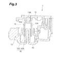
- Fig. 3 is a sectional view of an essential part of the swinging mechanism body.
- a side mirror 1 which is an electric mirror
- the mirror main body 3 is contained within the cover 2.
- a frame 4 and a swinging mechanism body 5 are provided in the cover 2 on a back face side of the mirror main body 3.
- the swinging mechanism body 5 is mounted on the cover 2 through the frame 4, and the mirror main body 3 is mounted on the surface of the swinging mechanism body 5.
- the frame 4 and the swinging mechanism body 5 arc arranged on the back face side of the mirror main body 3 and contained in the cover 2.
- the swinging mechanism body 5 has a mirror body 10 as shown in Fig. 2, and a motor 11, which is an actuator, is provided at the mirror body 10. Moreover, a worm wheel 12 is connected to the motor 11, and an adjust nut 13 is mounted on the worm wheel 12.
- the adjust nut 13 has a cylindrical body portion 13A and a spherical head portion 13B. Moreover, the body portion 13A has a hollow inside thereof as shown in Fig. 3, and a claw portion 13C having elasticity is provided at its base end side. Furthermore, a male thread member 10A is provided at the mirror body 10, and this male thread member 10A is inserted into the body portion 13A of the adjust nut 13.
- the claw portion 13C in the adjust nut 13 is engaged with the threaded portion in the male thread member 10A.
- a base member 14 is fixed to the mirror body 10, and a through hole 14A is formed in the base member 14.
- the adjust nut 13 passes the through hole 14A and projects in the opposite direction of the mirror body 10 sandwiching the base member 14 therebetween.
- a pivot plate 15 is disposed at a position in the mirror body 10 sandwiching the base member 14 therebetween.
- the pivot plate 15 has a hollowed fitting portion 15A having a spherical inner surface, as shown in Fig. 3, and the tip end of the adjust nut 13 is fitted in this fitting portion 15A.
- the mirror main body 3 shown in Fig. 1 is fixed.
- the worm wheel 12 and the adjust nut 13 mounted on this worm wheel 12 arc rotated according to the operating state of the motor 11.
- the adjust nut 13 is rotated, the adjust nut 13 is relatively moved close to / separated from with respect to the cover 2, and the pivot plate 15 in which the adjust nut 13 is fitted is relatively moved close to / separated from the cover 2.
- a mirror surface angle of the mirror main body 3 is adjusted. Also, if the mirror surface angle of the mirror main body 3 exceeds an allowable range, movement of the mirror main body 13 is suppressed.
- the worm wheel 12 and the adjust nut 13 continue to be rotated, but the claw portion 13C provided at the adjust nut 13 is bent and goes over the thread on the male thread member 10A provided on the mirror main body 10, and the adjust nut 13 idles.
- the bent claw portion 13C goes over the thread, a clutch noise is generated.
- the male thread member 10A and the claw portion 13C constitute a clutch mechanism 16.
- a mirror surface angle detection circuit for detecting a swing angle (mirror surface angle) of the mirror main body 3 with respect to the cover 2 is provided.
- Fig. 4 shows a circuit diagram of the mirror surface angle detection circuit.
- the circuit diagram in Fig. 4 shows a circuit for detecting a horizontal angle (angle around the vertical axis) for the mirror surface angle of the mirror main body 3, but a circuit for detecting a vertical angle (angle around the horizontal axis) is also provided as a similar circuit.
- a mirror surface angle detection circuit 20 is provided with a constant current circuit 21, a voltage sensor 22, an amplifier circuit 23, an offset circuit 24 and a clamp circuit 25.
- the constant current circuit 21 supplies a constant current to the voltage sensor 22.
- the voltage sensor 22 has a permanent magnet and a magnetic detection element for detecting a voltage generated from a relative positional change between the permanent magnet and the magnetic detection element with respect to the constant current supplied from the constant current circuit 21. Therefore, the voltage detected by the voltage sensor 22 varies according to the mirror surface angle.
- the amplifier circuit 23 amplifies the voltage detected by the voltage sensor 22.
- the voltage value amplified by the amplifier circuit 23 is outputted to the offset circuit 24.
- the offset circuit 24 offsets the voltage value amplified by the amplifier circuit 23 and adjusts it to a predetermined voltage value.
- the voltage value offset by the offset circuit 24 is outputted to the clamp circuit 25.
- the outputted voltage value is clamped to a predetermined upper limit value and a predetermined lower limit value, which are 4.5V and 0.5V in the embodiment respectively.
- the time when the voltage value becomes 5V and 0V is defined as a state where the mirror surface angle reaches the limit value, respectively.
- the mirror surface angle detection circuit 20 shown in Fig. 4 is a circuit as shown in Fig. 5, for a specific example.
- a control device 6 is connected to the mirror surface angle detection circuit 20, and the motor 11 is connected to the control device 6.
- the control device 6 performs opening / closing control of a switch element S by operating a mirror operating switch SW provided at a driver's seat of an automobile, which is not shown. By this opening / closing control, an electric current is supplied to the motor 11, and by operating the motor 11, the mirror surface angle of the mirror main body 3 is adjusted.
- a voltage detected by the voltage sensor 22 changes depending on the mirror surface angle of the mirror, and the motor 11 is controlled by this change of the voltage so as to suppress movement of the mirror main body 3 exceeding an allowable range.
- the voltage detected by the voltage sensor 22 is amplified by the amplifier circuit 23, and the voltage value is adjusted by the offset circuit 24 and thereafter, the voltage value is clamped to a maximum value and a minimum value set as limit values at the clamp circuit 25.
- a change in the voltage value outputted from the amplifier circuit 23 draws, as shown in Fig. 7a, a waveform increasing in proportion to the operating angle of the mirror surface angle of the mirror main body 3.
- the change in the voltage value outputted from the offset circuit 24 is, as shown in Fig. 7b, located at a position where the voltage value is offset.
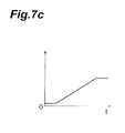
- the change in the voltage value outputted from the clamp circuit 25 forms, as shown in Fig. 7c, a waveform clamped to 4.5V, which is an upper limit value of the voltage value, and 0.5V, which is a lower limit value.
- the motor 11 when tilting the mirror main body 3 by driving the motor 11, if the motor I 1 tries to operate exceeding the allowable range of the mirror main body 3, the motor 11 idles by the clutch mechanism 16. At this time, the voltage detected by the voltage sensor 22 is in the largely oscillated state at the time when the allowable range is exceeded as shown by a straight line L1 in Fig. 8 before outputted by the clamp circuit 25. When this largely oscillated voltage is detected by the voltage sensor 22, it can be determined that the allowable range has been exceeded, but in this case, the accuracy to determine exceeding of the allowable range is low.
- the clamp circuit 25 is provided in the mirror surface angle detection circuit 20.
- This clamp circuit 25 clamps the detected voltage value to the upper limit value and the lower limit value, which are predetermined limit values, respectively. Therefore, it is detected by the voltage sensor 22, and the voltage value outputted from the clamp circuit 25 is, as shown by a straight line L2 in Fig. 8, clamped at a position closest to the allowable range.
- the control device 6 determines if this clamped voltage value continues for a certain period of time or not, and when it is determined that the clamped voltage value has continued for the certain period of time, the switch element S is controlled to be open. Therefore, the motor M can be stopped at a position closest to the allowable range.
- accurate detection can be made, and slipping of the clutch disposed in the actuator is stopped as quickly as possible, consequently generation of the clutch noise can be prevented.
- FIG. 9 is an exploded perspective view of an electric storage portion in the automobile electric mirror.
- An electric storage portion 30 has a speed reducer 31 integrally incorporated in the cover 2, and a motor 32 is mounted to the speed reducer 31.
- An output shaft 33 is mounted to the speed reducer 31, and a lower end of the output shalt 33 is mounted to a base member 40.
- the base member 40 is fixed to a body of a vehicle, which is not shown.
- a position of the cover 2 a using position standing for the use state and a stored position standing for the fold state are specified, and by driving the motor 32, the using position and the stored position are switched.
- the speed reducer 31 is provided with a clutch mechanism, not shown, and when the electric storage mirror is to rotate the cover 2 exceeding the using position or the stored position, the clutch mechanism slips so as to shut off a power from the motor 32.
- the motor is used as the actuator, but other driving mechanisms may be used.
- the motor is stopped to stop driving of the electric mirror, but such a mode may be adopted that the motor is disconnected from the clutch mechanism.
Landscapes
- Engineering & Computer Science (AREA)
- Multimedia (AREA)
- Mechanical Engineering (AREA)
- Rear-View Mirror Devices That Are Mounted On The Exterior Of The Vehicle (AREA)
Abstract
An electric mirror (1) control device is provided which can prevent generation of a clutch noise by stopping slipping of a clutch (16) provided at an actuator (10) as quickly as possible while preventing narrowing of an allowable range of a tilting angle of a mirror surface (3). In controlling an electric mirror, a control device (6) clamps a voltage value of a voltage applied to a motor (11) detected by a mirror surface angle detection circuit to a predetermined upper limit value and a predetermined lower limit value at a clamp circuit (25). Stop control of the motor is performed based on the voltage value clamped to the upper limit value and the lower limit value in this way.

Description
- The present invention relates to an electric mirror control device and particularly to an electric mirror control device in which mirror surface adjustment and electric storage are carried out in an automobile electric mirror.
- As an automobile electric mirror to be mounted on an automobile, there is a type providing a mirror main body and a case for containing this mirror main body. In this type of electric mirror, the mirror main body often includes such an arrangement that a mirror surface angle is adjustable with respect to the case, and some electric mirrors are equipped with an actuator for adjusting the mirror surface angle. This type of electric mirror is arranged so that the mirror surface angle can be adjusted by driving the actuator.
- In this type of electric mirror, a moving range of the mirror main body with respect to the case has an allowable range. If the mirror main body attempts to move beyond this allowable range, a clutch provided between the actuator and the mirror main body slips. Thus, by slipping of the clutch, the mirror main body is prevented from moving to a position beyond the allowable range. However, in case that the clutch is slipping, clutch noise is generated, which might give unpleasantness to a driver. Therefore, there is a problem that such a clutch noise should be eliminated or finished as soon as possible even if it is generated.
- Also, in some automobile electric mirrors, use state and fold state are defined and when the electric mirror is opened with respect to a vehicle, the mirror is defined to be in use state and when closed, to be in fold state. Further, in such electric mirrors, an actuator for rotationally driving the case is provided, and positions can be switched between the use state and fold state by driving the actuator. In this type of the automobile electric mirror, the above problem of the clutch noise is also generated.
- In order to cope with these problems, conventionally there is an electric mirror control device disclosed in
Japanese Patent Application Laid-Open No. 2003-200783 - However, with the electric mirror control device disclosed in the
above Patent Document 1, it is determined that the detected angle limit is reached when a detected angle value of the mirror surface becomes constant. Here, if the detected angle value to determine that the detected angle limit is reached is set low, the determination is made that the detected angel limit is reached before reaching an allowable range, and as a result, there is a fear that the allowable range of a tilting angle of the mirror surface might be narrowed. On the other hand, if the detected angle value is set high, though the allowable range of the tilting angle is widened, excessive tilting beyond the allowable range is promoted, which brings about a problem of more frequent clutch slipping. - Thus, an object of the present invention is to provide an electric mirror control device which can stop slipping of a clutch disposed in an actuator as quickly as possible while preventing the allowable range of a tilting angle of a mirror surface from being narrowed, and can prevent generation of clutch noise.
- An electric mirror control device for an automobile according to the present invention which solved the above problems includes a control method for an automobile electric mirror in which drive control of the electric mirror is performed by controlling an actuator for operating the electric mirror mounted on an automobile, comprising: a voltage sensor for detecting a voltage value applied to the actuator when the actuator is operated; a clamp means for clamping the voltage value detected by the voltage sensor at a predetermined limit value; and a stop control means for performing stop control of the actuator based on the voltage value detected by the voltage sensor and outputted through the clamp means.
- In the case that an operation limit (allowable range) of an electric mirror is arranged to be detected based on a voltage value detected by a voltage sensor, the operation limit deviation is induced with high possibility due to fluctuation of the voltage in the vicinity of the operation limit. The problem of operation limit deviation can be avoided by setting the limit value high, but in this case, stop of the actuator is delayed, which promotes clutch slipping. In this respect, in the electric mirror control device according to the present invention, a clamp means is provided for clamping a voltage value detected by the voltage sensor to a predetermined limit value, and stop control of the actuator is performed based on the voltage value detected by the voltage sensor and outputted through this clamp means. Therefore, since the voltage fluctuation detected at the operation limit can be prevented, the deviation generated in the vicinity of the operation limit can be reduced. Thus, since there is no need to set the limit value high, slipping of the clutch disposed in the actuator can be stopped as quickly as possible while preventing the allowable range of the tilting angle of the mirror surface from being narrowed, and the clutch noise generation can be prevented.
- As the limit value, at least one of a predetermined upper limit value or a predetermined lower limit value is defined, and a stop control means may be arranged so as to stop the actuator when the voltage value detected by the voltage sensor exceeds the predetermined upper limit value or drops below the predetermined lower limit value.
- If slippage occurrence is detected when the voltage value exceeds the predetermined upper limit value or drops below the predetermined lower limit value as described above, it becomes possible to stop slipping of the clutch disposed in the actuator as quickly as possible while preventing favorably the allowable range of the tilting angle of the mirror surface from being narrowed, and thus the clutch noise generation can be prevented.
- Moreover, the electric mirror may be arranged so that a case is provided with a mirror main body which is mounted thereto, a mirror surface angle is adjustable with respect to the case in the mirror main body, and the actuator drives the mirror main body so as to adjust the mirror surface angle of the mirror main body.
- As described above, the actuator drive control is performed for adjusting the mirror surface angle on the occasion of adjusting the mirror surface angle of the mirror main body. In that case a problem of a slip noise occurs, but the occurrence of the slip noise can be prevented.
- According to a control method of an automobile electric mirror of the present invention, slipping of a clutch disposed in an actuator can be stopped as quickly as possible, and occurrence of a clutch noise can be effectively prevented.
- Fig. 1 is an exploded perspective view of an electric mirror used in an embodiment of the present invention;
- Fig. 2 is an exploded perspective view of a mirror holder and a swinging mechanism body;
- Fig. 3 is a sectional view of an essential part of the swinging mechanism body;
- Fig. 4 is a circuit diagram of a mirror-surface angle detection circuit;
- Fig. 5 is a circuit diagram of the mirror-surface angle detection circuit as a specific example;
- Fig. 6 is a circuit diagram of the electric mirror;
- Fig. 7a is a graph showing a waveform of a voltage value outputted from an amplifier circuit;
- Fig. 7b is a graph showing a waveform of a voltage value outputted from an offset circuit;
- Fig. 7c is a graph showing a waveform of a voltage value outputted from a clamp circuit;
- Fig. 8 is a graph showing a change in the voltage value;
- Fig. 9 is an exploded perspective view of an electric storage portion in an automobile electric mirror.
- A preferred embodiment of the present invention will be described below referring to the drawings. Fig. 1 is an exploded perspective view of an electric mirror used in the preferred embodiment of the present invention, Fig. 2 is an exploded perspective view of a mirror holder and a swinging mechanism body, and Fig. 3 is a sectional view of an essential part of the swinging mechanism body. As shown in Fig. 1, a
side mirror 1, which is an electric mirror, is provided with acover 2 and a mirror main body 3, and the mirror main body 3 is contained within thecover 2. Aframe 4 and a swinging mechanism body 5 are provided in thecover 2 on a back face side of the mirror main body 3. The swinging mechanism body 5 is mounted on thecover 2 through theframe 4, and the mirror main body 3 is mounted on the surface of the swinging mechanism body 5. Theframe 4 and the swinging mechanism body 5 arc arranged on the back face side of the mirror main body 3 and contained in thecover 2. - The swinging mechanism body 5 has a
mirror body 10 as shown in Fig. 2, and amotor 11, which is an actuator, is provided at themirror body 10. Moreover, aworm wheel 12 is connected to themotor 11, and anadjust nut 13 is mounted on theworm wheel 12. Theadjust nut 13 has acylindrical body portion 13A and aspherical head portion 13B. Moreover, thebody portion 13A has a hollow inside thereof as shown in Fig. 3, and aclaw portion 13C having elasticity is provided at its base end side. Furthermore, amale thread member 10A is provided at themirror body 10, and thismale thread member 10A is inserted into thebody portion 13A of theadjust nut 13. Also, theclaw portion 13C in theadjust nut 13 is engaged with the threaded portion in themale thread member 10A. Moreover, abase member 14 is fixed to themirror body 10, and a throughhole 14A is formed in thebase member 14. Theadjust nut 13 passes the throughhole 14A and projects in the opposite direction of themirror body 10 sandwiching thebase member 14 therebetween. - Also, at a position in the
mirror body 10 sandwiching thebase member 14 therebetween, apivot plate 15 is disposed. Thepivot plate 15 has a hollowedfitting portion 15A having a spherical inner surface, as shown in Fig. 3, and the tip end of the adjustnut 13 is fitted in thisfitting portion 15A. Moreover, to thispivot plate 15, the mirror main body 3 shown in Fig. 1 is fixed. - Then, when the
motor 11 is operated, theworm wheel 12 and the adjustnut 13 mounted on thisworm wheel 12 arc rotated according to the operating state of themotor 11. When the adjustnut 13 is rotated, the adjustnut 13 is relatively moved close to / separated from with respect to thecover 2, and thepivot plate 15 in which the adjustnut 13 is fitted is relatively moved close to / separated from thecover 2. Thus a mirror surface angle of the mirror main body 3 is adjusted. Also, if the mirror surface angle of the mirror main body 3 exceeds an allowable range, movement of the mirrormain body 13 is suppressed. At this time, theworm wheel 12 and the adjustnut 13 continue to be rotated, but theclaw portion 13C provided at the adjustnut 13 is bent and goes over the thread on themale thread member 10A provided on the mirrormain body 10, and the adjustnut 13 idles. When thebent claw portion 13C goes over the thread, a clutch noise is generated. Themale thread member 10A and theclaw portion 13C constitute aclutch mechanism 16. - Moreover, on the
side mirror 1, a mirror surface angle detection circuit for detecting a swing angle (mirror surface angle) of the mirror main body 3 with respect to thecover 2 is provided. Fig. 4 shows a circuit diagram of the mirror surface angle detection circuit. The circuit diagram in Fig. 4 shows a circuit for detecting a horizontal angle (angle around the vertical axis) for the mirror surface angle of the mirror main body 3, but a circuit for detecting a vertical angle (angle around the horizontal axis) is also provided as a similar circuit. - As shown in Fig. 4, a mirror surface
angle detection circuit 20 is provided with a constantcurrent circuit 21, avoltage sensor 22, anamplifier circuit 23, an offsetcircuit 24 and aclamp circuit 25. The constantcurrent circuit 21 supplies a constant current to thevoltage sensor 22. Thevoltage sensor 22 has a permanent magnet and a magnetic detection element for detecting a voltage generated from a relative positional change between the permanent magnet and the magnetic detection element with respect to the constant current supplied from the constantcurrent circuit 21. Therefore, the voltage detected by thevoltage sensor 22 varies according to the mirror surface angle. - The
amplifier circuit 23 amplifies the voltage detected by thevoltage sensor 22. The voltage value amplified by theamplifier circuit 23 is outputted to the offsetcircuit 24. The offsetcircuit 24 offsets the voltage value amplified by theamplifier circuit 23 and adjusts it to a predetermined voltage value. The voltage value offset by the offsetcircuit 24 is outputted to theclamp circuit 25. In theclamp circuit 25, the outputted voltage value is clamped to a predetermined upper limit value and a predetermined lower limit value, which are 4.5V and 0.5V in the embodiment respectively. Here, in the embodiment, the time when the voltage value becomes 5V and 0V is defined as a state where the mirror surface angle reaches the limit value, respectively. The mirror surfaceangle detection circuit 20 shown in Fig. 4 is a circuit as shown in Fig. 5, for a specific example. - Furthermore, as shown in Fig. 6, a
control device 6 is connected to the mirror surfaceangle detection circuit 20, and themotor 11 is connected to thecontrol device 6. Thecontrol device 6 performs opening / closing control of a switch element S by operating a mirror operating switch SW provided at a driver's seat of an automobile, which is not shown. By this opening / closing control, an electric current is supplied to themotor 11, and by operating themotor 11, the mirror surface angle of the mirror main body 3 is adjusted. - Next, an operation of the electric mirror control device according to the embodiment will be described. In the electric mirror control device according to the embodiment, a voltage detected by the
voltage sensor 22 changes depending on the mirror surface angle of the mirror, and themotor 11 is controlled by this change of the voltage so as to suppress movement of the mirror main body 3 exceeding an allowable range. Here, in the mirror surfaceangle detection circuit 20, the voltage detected by thevoltage sensor 22 is amplified by theamplifier circuit 23, and the voltage value is adjusted by the offsetcircuit 24 and thereafter, the voltage value is clamped to a maximum value and a minimum value set as limit values at theclamp circuit 25. For example, if the mirror main body 3 is moved in a certain direction by operating themotor 11, when the voltage detected by thevoltage sensor 22 is outputted to theamplifier circuit 23, a change in the voltage value outputted from theamplifier circuit 23 draws, as shown in Fig. 7a, a waveform increasing in proportion to the operating angle of the mirror surface angle of the mirror main body 3. When this voltage is outputted to the offsetcircuit 24, the change in the voltage value outputted from the offsetcircuit 24 is, as shown in Fig. 7b, located at a position where the voltage value is offset. When this voltage is outputted to theclamp circuit 25, the change in the voltage value outputted from theclamp circuit 25 forms, as shown in Fig. 7c, a waveform clamped to 4.5V, which is an upper limit value of the voltage value, and 0.5V, which is a lower limit value. - On the one hand, when tilting the mirror main body 3 by driving the
motor 11, if the motor I 1 tries to operate exceeding the allowable range of the mirror main body 3, themotor 11 idles by theclutch mechanism 16. At this time, the voltage detected by thevoltage sensor 22 is in the largely oscillated state at the time when the allowable range is exceeded as shown by a straight line L1 in Fig. 8 before outputted by theclamp circuit 25. When this largely oscillated voltage is detected by thevoltage sensor 22, it can be determined that the allowable range has been exceeded, but in this case, the accuracy to determine exceeding of the allowable range is low. - On the other hand, in the electric mirror control device in this preferred embodiment, the
clamp circuit 25 is provided in the mirror surfaceangle detection circuit 20. Thisclamp circuit 25 clamps the detected voltage value to the upper limit value and the lower limit value, which are predetermined limit values, respectively. Therefore, it is detected by thevoltage sensor 22, and the voltage value outputted from theclamp circuit 25 is, as shown by a straight line L2 in Fig. 8, clamped at a position closest to the allowable range. Thecontrol device 6 determines if this clamped voltage value continues for a certain period of time or not, and when it is determined that the clamped voltage value has continued for the certain period of time, the switch element S is controlled to be open. Therefore, the motor M can be stopped at a position closest to the allowable range. Thus, without narrowing the allowable range of the tilting angle of the mirror surface, accurate detection can be made, and slipping of the clutch disposed in the actuator is stopped as quickly as possible, consequently generation of the clutch noise can be prevented. - In the above embodiment, an example of mirror surface angle adjustment was described for control of an automobile electric mirror, but the similar control can be also performed for control of electric storage. Fig. 9 is an exploded perspective view of an electric storage portion in the automobile electric mirror. An
electric storage portion 30 has aspeed reducer 31 integrally incorporated in thecover 2, and amotor 32 is mounted to thespeed reducer 31. Anoutput shaft 33 is mounted to thespeed reducer 31, and a lower end of the output shalt 33 is mounted to abase member 40. Thebase member 40 is fixed to a body of a vehicle, which is not shown. Also, as a position of thecover 2, a using position standing for the use state and a stored position standing for the fold state are specified, and by driving themotor 32, the using position and the stored position are switched. Moreover, thespeed reducer 31 is provided with a clutch mechanism, not shown, and when the electric storage mirror is to rotate thecover 2 exceeding the using position or the stored position, the clutch mechanism slips so as to shut off a power from themotor 32. - As for the
motor 32 in theelectric storage portion 30 having the above arrangement as well, there is a problem of clutch noise generated while slipping of the clutch mechanism disposed in thespeed reducer 31 as with theabove motor 11 for adjusting the mirror surface angle. In order to cope with this, the generation of the clutch noise while slipping of the clutch mechanism can be prevented by performing the similar control as that of thecontrol device 6. - The preferred embodiments of the present invention have been described so far but the present invention is not limited to the above embodiments. For example, in the above embodiment, the motor is used as the actuator, but other driving mechanisms may be used. Also, the motor is stopped to stop driving of the electric mirror, but such a mode may be adopted that the motor is disconnected from the clutch mechanism.
Claims (3)
- An electric mirror control device, including a control method for an automobile electric mirror in which drive control of the electric mirror is performed by controlling an actuator for operating the electric mirror mounted on an automobile, comprising:a voltage sensor for detecting a voltage value applied to the actuator when the actuator is in operation;a clamp means for clamping the voltage value detected by the voltage sensor to a predetermined limit value; anda stop control means for performing stop control of the actuator based on the voltage value detected by the voltage sensor and outputted through the clamp means.
- The electric mirror control device according to claim 1, wherein at least one of a predetermined upper limit value and a predetermined lower limit value is set as the limit value, and wherein
the stop control means stops the actuator when the voltage value detected by the voltage sensor exceeds the predetermined upper limit value or drops below the predetermined lower limit value. - The electric mirror control device according to claim 1 or 2, wherein the electric mirror has a case to which a mirror main body is mounted, a mirror surface angle of the mirror main body being adjustable with respect to the case, and
the actuator drives the mirror main body so that the mirror surface angle of the mirror main body is adjusted.
Applications Claiming Priority (1)
| Application Number | Priority Date | Filing Date | Title |
|---|---|---|---|
| JP2005223331A JP5038606B2 (en) | 2005-08-01 | 2005-08-01 | Electric mirror control device |
Publications (1)
| Publication Number | Publication Date |
|---|---|
| EP1749697A1 true EP1749697A1 (en) | 2007-02-07 |
Family
ID=37022988
Family Applications (1)
| Application Number | Title | Priority Date | Filing Date |
|---|---|---|---|
| EP06115204A Withdrawn EP1749697A1 (en) | 2005-08-01 | 2006-06-09 | Electric mirror control device |
Country Status (3)
| Country | Link |
|---|---|
| US (2) | US20070024996A1 (en) |
| EP (1) | EP1749697A1 (en) |
| JP (1) | JP5038606B2 (en) |
Cited By (1)
| Publication number | Priority date | Publication date | Assignee | Title |
|---|---|---|---|---|
| CN104044510A (en) * | 2014-06-04 | 2014-09-17 | 常州市凯凌车配有限公司 | Electrically-folded outside rear-view mirror for passenger car |
Families Citing this family (11)
| Publication number | Priority date | Publication date | Assignee | Title |
|---|---|---|---|---|
| USD597460S1 (en) * | 2008-11-20 | 2009-08-04 | Ford Motor Company | Pair of vehicle mirrors |
| USD631414S1 (en) * | 2010-02-19 | 2011-01-25 | Toyota Jidosha Kabushiki Kaisha | Mirror for an automobile |
| US10537392B2 (en) * | 2010-03-03 | 2020-01-21 | Brainlab Ag | Method for enabling medical navigation with minimised invasiveness |
| US8783883B2 (en) * | 2010-08-30 | 2014-07-22 | Honda Motor Co., Ltd. | Method for controlling power to a motor in a vehicle door mirror |
| JP5501950B2 (en) * | 2010-12-27 | 2014-05-28 | 株式会社村上開明堂 | Control method and control device for vehicle mirror |
| JP5758251B2 (en) * | 2011-09-20 | 2015-08-05 | 株式会社村上開明堂 | door mirror |
| WO2016080834A2 (en) * | 2014-11-19 | 2016-05-26 | Mci (Mirror Controls International) Netherlands B.V. | Automatically adjustable mirror assembly |
| NL2013827B1 (en) * | 2014-11-19 | 2016-10-11 | MCI (Mirror Controls International) Netherlands B V | Automatically adjustable mirror assembly. |
| NL2018400B1 (en) * | 2017-02-21 | 2018-09-17 | Mci Mirror Controls Int Netherlands B V | Adjustment instrument and method |
| DE102017216860B4 (en) | 2017-09-22 | 2020-03-19 | Kennametal Inc. | Cutting tool, machining device and method for machining workpieces |
| US11279286B2 (en) * | 2020-04-15 | 2022-03-22 | Motherson Innovations Company Limited | Actuator assembly for mirror |
Citations (5)
| Publication number | Priority date | Publication date | Assignee | Title |
|---|---|---|---|---|
| DE3923174A1 (en) * | 1988-07-13 | 1990-02-01 | Tokai Rika Co Ltd | ELECTRIC REAR MIRROR DEVICE FOR A MOTOR VEHICLE |
| WO1996002849A1 (en) * | 1994-07-19 | 1996-02-01 | Honeywell Inc. | Temperature compensation circuit for a hall effect element |
| US6094027A (en) * | 1999-01-11 | 2000-07-25 | Donnelly Corporation | Vehicle memory mirror position transducer |
| EP1097845A2 (en) * | 1999-11-02 | 2001-05-09 | Donnelly Hohe GmbH & Co. KG | Exterior rear view mirror with position sensor |
| JP2003200783A (en) | 2002-01-08 | 2003-07-15 | Nissan Motor Co Ltd | Electric mirror control device |
Family Cites Families (15)
| Publication number | Priority date | Publication date | Assignee | Title |
|---|---|---|---|---|
| US4770522A (en) * | 1987-11-02 | 1988-09-13 | Siegel-Robert, Inc. | Automobile mirror position sensor and adjuster assembly |
| US4798967A (en) * | 1988-03-24 | 1989-01-17 | Murakami Kaimeido Co | Control system for foldable outside rearview mirror |
| EP0348700B1 (en) * | 1988-06-09 | 1994-01-12 | Hohe Kg | External mirror for a motor vehicle with a reverse gear |
| US5033835A (en) * | 1988-12-09 | 1991-07-23 | Platzer Jr George E | Remote control mirror with angular viewing adjustments |
| US4981349A (en) * | 1989-09-01 | 1991-01-01 | Kabushiki Kaisha Matsuyama Seisakusho | Rearview mirror assembly for automobiles including positioning means with a recess surface extending uniformly horizontally |
| JP2585113B2 (en) * | 1989-12-20 | 1997-02-26 | 株式会社村上開明堂 | Door lock interlocking electric retractable mirror system |
| JP2771686B2 (en) * | 1990-08-29 | 1998-07-02 | 株式会社東海理化電機製作所 | Automotive door mirror control device |
| JPH0840146A (en) * | 1994-08-03 | 1996-02-13 | Murakami Kaimeidou:Kk | Control device for electrically storing type door mirror |
| JPH08156685A (en) * | 1994-12-07 | 1996-06-18 | Ichikoh Ind Ltd | Remote control mirror drive mechanism |
| US5703732A (en) * | 1995-01-17 | 1997-12-30 | Lowell Engineering Corporation | Exterior mirror with indexing and control pivoting |
| US5811957A (en) * | 1995-12-21 | 1998-09-22 | General Motors Corporation | Speed sensorless hybrid vector controlled induction motor with zero speed operation |
| JP3396018B2 (en) * | 1997-03-25 | 2003-04-14 | 株式会社村上開明堂 | Mirror position detector |
| US5952802A (en) * | 1997-12-08 | 1999-09-14 | Delco Electronics Corp. | Method of controlling an automotive mirror |
| JP2004182126A (en) * | 2002-12-04 | 2004-07-02 | Mitsubishi Cable Ind Ltd | Control device for remote-controlled side mirror of automobile and control method used for the same |
| JP4012460B2 (en) * | 2002-11-28 | 2007-11-21 | 株式会社東海理化電機製作所 | Outer mirror device for vehicle |
-
2005
- 2005-08-01 JP JP2005223331A patent/JP5038606B2/en not_active Expired - Fee Related
-
2006
- 2006-06-06 US US11/447,108 patent/US20070024996A1/en not_active Abandoned
- 2006-06-09 EP EP06115204A patent/EP1749697A1/en not_active Withdrawn
-
2009
- 2009-01-12 US US12/352,264 patent/US7722200B2/en not_active Expired - Fee Related
Patent Citations (5)
| Publication number | Priority date | Publication date | Assignee | Title |
|---|---|---|---|---|
| DE3923174A1 (en) * | 1988-07-13 | 1990-02-01 | Tokai Rika Co Ltd | ELECTRIC REAR MIRROR DEVICE FOR A MOTOR VEHICLE |
| WO1996002849A1 (en) * | 1994-07-19 | 1996-02-01 | Honeywell Inc. | Temperature compensation circuit for a hall effect element |
| US6094027A (en) * | 1999-01-11 | 2000-07-25 | Donnelly Corporation | Vehicle memory mirror position transducer |
| EP1097845A2 (en) * | 1999-11-02 | 2001-05-09 | Donnelly Hohe GmbH & Co. KG | Exterior rear view mirror with position sensor |
| JP2003200783A (en) | 2002-01-08 | 2003-07-15 | Nissan Motor Co Ltd | Electric mirror control device |
Non-Patent Citations (1)
| Title |
|---|
| PATENT ABSTRACTS OF JAPAN vol. 2003, no. 11 5 November 2003 (2003-11-05) * |
Cited By (1)
| Publication number | Priority date | Publication date | Assignee | Title |
|---|---|---|---|---|
| CN104044510A (en) * | 2014-06-04 | 2014-09-17 | 常州市凯凌车配有限公司 | Electrically-folded outside rear-view mirror for passenger car |
Also Published As
| Publication number | Publication date |
|---|---|
| US20070024996A1 (en) | 2007-02-01 |
| JP5038606B2 (en) | 2012-10-03 |
| US7722200B2 (en) | 2010-05-25 |
| JP2007038761A (en) | 2007-02-15 |
| US20090122433A1 (en) | 2009-05-14 |
Similar Documents
| Publication | Publication Date | Title |
|---|---|---|
| US7722200B2 (en) | Electric mirror control device | |
| JP5501950B2 (en) | Control method and control device for vehicle mirror | |
| CN103270661B (en) | For the method and apparatus of the adjusting device of controller motor vehicle | |
| JP4287291B2 (en) | Vehicle throttle device | |
| CN114174626A (en) | Drive device for adjusting a vehicle structural component | |
| US20160250970A1 (en) | Full display mirror actuator with linkage arm | |
| EP1027228B1 (en) | Rear-view mirror apparatus for a road vehicle | |
| US12054075B2 (en) | Seat control device | |
| JP4105735B2 (en) | Seat rotating device and vehicle equipped with the seat rotating device | |
| JP2003107554A (en) | Support structure for vibration-proof correcting lens | |
| JPH1092207A (en) | Headlight optical axis adjustment mechanism for vehicles | |
| US7445190B2 (en) | Mirror adjustment mechanism, wing mirror unit and method | |
| EP0463563A1 (en) | Electrical remote-control mirror assembly | |
| JP2007168723A (en) | Steering wheel position adjusting device and position adjusting method | |
| JP2000289626A (en) | Steering position adjustment control device | |
| JP4537900B2 (en) | Control method of electric mirror for automobile | |
| JP2000276927A (en) | Optical axis adjustment device | |
| JP2007106180A (en) | Electric steering device | |
| JP2000016178A (en) | Rearview mirror tilting device for vehicles | |
| KR20050024913A (en) | Apparatus for mirror automatic setting on vehicle and method thereof | |
| JP2004278752A (en) | Selection assisting apparatus of automatic transmission | |
| JP2005133449A (en) | Power window device | |
| KR100623331B1 (en) | Mirror driving device of motorized outdoor mirror with improved fixed shaft output voltage characteristics | |
| CN119840701A (en) | Adjustment drive method for operating an electrically adjustable steering column, control unit, steering column and motor vehicle | |
| KR20020047929A (en) | Locking system of door |
Legal Events
| Date | Code | Title | Description |
|---|---|---|---|
| PUAI | Public reference made under article 153(3) epc to a published international application that has entered the european phase |
Free format text: ORIGINAL CODE: 0009012 |
|
| AK | Designated contracting states |
Kind code of ref document: A1 Designated state(s): AT BE BG CH CY CZ DE DK EE ES FI FR GB GR HU IE IS IT LI LT LU LV MC NL PL PT RO SE SI SK TR |
|
| AX | Request for extension of the european patent |
Extension state: AL BA HR MK YU |
|
| AKX | Designation fees paid | ||
| STAA | Information on the status of an ep patent application or granted ep patent |
Free format text: STATUS: THE APPLICATION IS DEEMED TO BE WITHDRAWN |
|
| 18D | Application deemed to be withdrawn |
Effective date: 20070208 |
|
| REG | Reference to a national code |
Ref country code: DE Ref legal event code: 8566 |