EP1748640A1 - Camera apparatus - Google Patents
Camera apparatus Download PDFInfo
- Publication number
- EP1748640A1 EP1748640A1 EP06013767A EP06013767A EP1748640A1 EP 1748640 A1 EP1748640 A1 EP 1748640A1 EP 06013767 A EP06013767 A EP 06013767A EP 06013767 A EP06013767 A EP 06013767A EP 1748640 A1 EP1748640 A1 EP 1748640A1
- Authority
- EP
- European Patent Office
- Prior art keywords
- air
- case
- port
- camera apparatus
- imaginary axis
- Prior art date
- Legal status (The legal status is an assumption and is not a legal conclusion. Google has not performed a legal analysis and makes no representation as to the accuracy of the status listed.)
- Granted
Links
Images


Classifications
-
- G—PHYSICS
- G08—SIGNALLING
- G08B—SIGNALLING OR CALLING SYSTEMS; ORDER TELEGRAPHS; ALARM SYSTEMS
- G08B13/00—Burglar, theft or intruder alarms
- G08B13/18—Actuation by interference with heat, light, or radiation of shorter wavelength; Actuation by intruding sources of heat, light, or radiation of shorter wavelength
- G08B13/189—Actuation by interference with heat, light, or radiation of shorter wavelength; Actuation by intruding sources of heat, light, or radiation of shorter wavelength using passive radiation detection systems
- G08B13/194—Actuation by interference with heat, light, or radiation of shorter wavelength; Actuation by intruding sources of heat, light, or radiation of shorter wavelength using passive radiation detection systems using image scanning and comparing systems
- G08B13/196—Actuation by interference with heat, light, or radiation of shorter wavelength; Actuation by intruding sources of heat, light, or radiation of shorter wavelength using passive radiation detection systems using image scanning and comparing systems using television cameras
- G08B13/19617—Surveillance camera constructional details
- G08B13/19619—Details of casing
-
- H—ELECTRICITY
- H04—ELECTRIC COMMUNICATION TECHNIQUE
- H04N—PICTORIAL COMMUNICATION, e.g. TELEVISION
- H04N23/00—Cameras or camera modules comprising electronic image sensors; Control thereof
- H04N23/50—Constructional details
- H04N23/51—Housings
-
- G—PHYSICS
- G08—SIGNALLING
- G08B—SIGNALLING OR CALLING SYSTEMS; ORDER TELEGRAPHS; ALARM SYSTEMS
- G08B13/00—Burglar, theft or intruder alarms
- G08B13/18—Actuation by interference with heat, light, or radiation of shorter wavelength; Actuation by intruding sources of heat, light, or radiation of shorter wavelength
- G08B13/189—Actuation by interference with heat, light, or radiation of shorter wavelength; Actuation by intruding sources of heat, light, or radiation of shorter wavelength using passive radiation detection systems
- G08B13/194—Actuation by interference with heat, light, or radiation of shorter wavelength; Actuation by intruding sources of heat, light, or radiation of shorter wavelength using passive radiation detection systems using image scanning and comparing systems
- G08B13/196—Actuation by interference with heat, light, or radiation of shorter wavelength; Actuation by intruding sources of heat, light, or radiation of shorter wavelength using passive radiation detection systems using image scanning and comparing systems using television cameras
- G08B13/19617—Surveillance camera constructional details
- G08B13/1963—Arrangements allowing camera rotation to change view, e.g. pivoting camera, pan-tilt and zoom [PTZ]
Abstract
Description
- The present invention contains subject matter related to
Japanese Patent Application JP 2005-216895 filed in the Japanese Patent Office on July 27, 2005 - The present invention relates to camera apparatuses.
- A camera apparatus (PTZ, Pan/Tilt/Zoom camera) for remotely panning, tilting and zooming a camera has been suggested (refer to,
Japanese Unexamined Patent Application Publication No. 2000-244781 - Such a camera apparatus includes a base attached to the ceiling of the building, an outer case assembled on the base so as to turn (pan) around a first imaginary axis which passes through the base, an inner case assembled in the outer case so as to turn (tilt) around a second imaginary axis which extends in a plane intersecting with the first imaginary axis, a camera and a board for controlling operation of the camera respectively assembled in the inner case.
- The camera includes a lens barrel in which an imaging optical system is accommodated an imaging element for imaging a subject guided by the imaging optical system is provided in the lens barrel.
- The lens barrel has a focusing mechanism for performing focusing operation and a zooming mechanism for performing zooming operation. The focusing operation is performed by moving a movable lens, which is provided in a manner movable in an optical axis direction, in the optical axis direction of the imaging optical system from among a plurality of lenses of the imaging optical system.
- A driver circuit for driving a drive source (motor) of the focusing mechanism and zooming mechanism, a signal processing circuit for generating a video signal to be supplied to a display or the like by driving the imaging element and processing an imaging signal output from the imaging element, and so forth are mounted on the board. These circuits are composed of various electric components.
- Since these electric components generate heat upon operation, these electric components are cooled with a heat sink.
- However, in recent years, even through the electric components are cooled with the heat sink, the heat generated by the electric components is likely to be transmitted to the lens barrel, since a distance between the lens barrel and the board is reduced due to downsizing of the camera apparatus.
- Incidentally, as the movable lens moves in the lens barrel, a part of the lens barrel slides on a part of the movable lens. Accordingly, a lubricant such as a grease is applied to these sliding parts.
- Owing to this, if the lubricant is heated with the heat generated by the electric components, the lubricant may be deteriorated, thereby being disadvantageous to secure durability of the camera.
- In view of above-described problem, it is desirable to provide a camera apparatus capable of improving durability of a camera by effectively cooling electric components and being advantageous to be downsized.
- According to an embodiment of the present invention, there is provided a camera apparatus including: a base; an outer case being assembled on the base so as to turn around a first imaginary axis which passes through the base and having an outer opening extended in the outer case; an inner case being assembled in the outer case so as to turn around a second imaginary line which extends in a plane intersecting with the first imaginary axis, and having an inner opening to be moved along the outer opening when the inner case turns around the second imaginary axis; a supporting member assembled in the inner case; a camera provided at the supporting member, the camera being capable of imaging a subject through the outer opening and the inner opening, and performing focusing operation and zooming operation; and a board provided at the supporting member, the board having a circuit for controlling the focusing operation and the zooming operation and a circuit for processing an image signal generated by imaging the subject, in which a cooling fan is provided in the inner case for blowing cooling air over the board, an air inlet is provided in the inner case for the cooling air, an air outlet is provided in the inner case for the cooling air which has been blown over the board, an air lead-in port is provided in the outer case for leading the cooling air to the air inlet, and an air lead-out port is provided in the outer case for leading the cooling air out of the outer case.
- With such an embodiment, the heat generated by the electric components of the board can be effectively cooled with the cooling air to reduce the heat transmitted to the camera in the inner case. Therefore, the lubricant such as the grease applied to the sliding parts of the camera can be reliably prevented from being deteriorated, thus addressing the problem related to the heat generated by the electric components upon the downsizing of the camera apparatus, and being advantageous to downsize the camera apparatus.
-
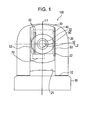
- Fig. 1 is a front view of a
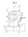
camera apparatus 100 according to a first embodiment of the present invention; - Fig. 2 is a side view of the
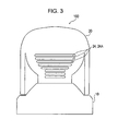
camera apparatus 100; - Fig. 3 is a rear view of the
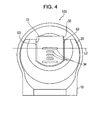
camera apparatus 100; - Fig. 4 is a plan view of the
camera apparatus 100; - Fig. 5 is a cross section showing the inner structure of the
camera apparatus 100; - Fig. 6 is a cross section taken along line VI-VI of Fig. 5;
- Fig. 7 is a view taken along the arrow B of Fig. 6;
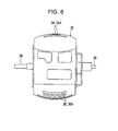
- Fig. 8 is a rear view of an
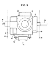
inner case 30; - Fig. 9 is an explanatory view showing a state where a
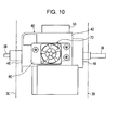
camera 50, acooling fan 70 and the like are attached to a supportingmember 40; - Fig. 10 is a view taken along the arrow A of Fig. 9;
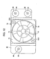
- Fig. 11 is an explanatory view showing a state where the
cooling fan 70 is attached to amounting plate 80; - Fig. 12 is a view taken along the arrow A of Fig. 11; and
- Fig. 13 is an explanatory view of a mounting part of the
cooling fan 70 to themounting plate 80. - An embodiment of a camera apparatus according to the present invention will be described below with reference to the attached drawings.
- Fig. 1 is a front view of a
camera apparatus 100 according to a first embodiment, Fig. 2 is a side view of thecamera apparatus 100, Fig. 3 is a rear view of thecamera apparatus 100, and Fig. 4 is a plan view of thecamera apparatus 100. - As shown in Figs. 1 to 4, the
camera apparatus 100 includes abase 10, anouter case 20 assembled on thebase 10, aninner case 30 assembled in theouter case 20, a supportingmember 40 assembled in theinner case 30, acamera 50 andboards 60 assembled in the supportingmember 40, acooling fan 70 for cooling theboards 60, and the like. - The
base 10 is attached to a ceiling or a wall inside a room, or to a pillar inside/outside the room, and has amounting surface 12 to which theouter case 20 is attached. - As shown in Figs. 1 and 2, the
outer case 20 is assembled on thebase 10 so as to turn around a first imaginary axis L1 which passes through thebase 10. In the present embodiment, theouter case 20 is turnable through 340 degrees around the first imaginary axis L1. In particular, theouter case 20 is turnable through 170 degrees leftward and rightward with respect to a reference position where the optical axis of thecamera 50 is set to the front. - The first imaginary axis L1 is perpendicular to the
mounting surface 12. Theouter case 20 is provided to extend in a direction perpendicular to themounting surface 12. In the present embodiment, the first imaginary axis L1 is a vertical axis. - As shown in Figs. 1, 2 and 4, the
outer case 20 has a front part formed to be cylindrical, and a rear part formed to be spherically bulged toward the rear at the upper part thereof and provided with adisk 21 at the lower part thereof. Thedisk 21 turns on themounting surface 12. - As shown in Figs. 1 and 4, an
outer opening 22 is provided in theouter case 20, theouter opening 22 extending from the front part to the top of theouter case 20 with a regular width. Theouter opening 22 extends from the lower end of theouter case 20, where thedisk 21 is exposed, to the top thereof along a direction parallel to the first imaginary axis L1. - As shown in Figs. 2 and 3, a plurality of slits 24A are provided at the lower rear part of the
outer case 20, the slits 24A horizontally extending and being spaced to each other in the vertical direction. The plurality of slits 24A define an air circulation port 24. - Although not shown, the
outer case 20 is dividable into front and rear parts, so that theinner case 30 is assembled therein. - Fig. 5 is a cross section showing the inner structure of the
camera apparatus 100, Fig. 6 is a cross section taken along line VI-VI of Fig. 5, Fig. 7 is a view taken along the arrow B of Fig. 6, and Fig. 8 is a rear view of theinner case 30. - As shown in Figs. 1 and 4, the
inner case 30 is assembled in theouter case 20 so as to turn around a second imaginary axis L2 extending in a plane perpendicular to the first imaginary axis L1. In the present embodiment, theinner case 30 is turnable through 120 degrees around the second imaginary axis L2. In particular, in such a case where thebase 10 is attached to a horizontal plane, theinner case 30 is turnable through 30 degrees in a direction toward thebase 10 and 90 degrees in a direction away from thebase 10 with respect to the reference position with the optical axis of thecamera 50 set in a horizontal direction. The second imaginary axis L2 is a horizontal axis. - As shown in Fig. 1, the
inner case 30 has a regular width smaller than that of theouter opening 22 to be assembled in theouter case 20 through theouter opening 22. As shown in Fig. 5, theinner case 30 has flat front and rear faces parallel to each other, and spherical upper and lower faces. As shown in Fig. 6, the left and right faces of theinner case 30 are circular with the center being open. - As shown in Fig. 5, a plurality of upper slits 34A and a plurality of lower slits 36A are respectively provided in the upper and lower faces of the
inner case 30. The plurality of upper slits 34A define anair outlet 34, whereas the plurality of lower slits 36A define an air inlet 36. - As shown in Figs. 1, 4 and 5, the gaps S1, S2, S3 and S4 are respectively secured between: the upper face of the
inner case 30 and an upper rear part of an inner face of theouter case 20; the rear face of theinner case 30 and a rear part of the inner face of theouter case 20; the left and right faces of theinner case 30 and left and right parts of the inner face of theouter case 20; and the lower face of theinner case 30 and thedisk 21. - The
inner case 30 is disposed such that the front part thereof is exposed from theouter opening 22. Aninner opening 32 is provided at the front part of theinner case 30. - As shown in Fig. 8,
spindles 38 extend from the center of opposing parts in the width direction of theinner case 30 and project outward from the opposing parts. Bearings (not shown) are provided in theouter case 20 and thespindles 38 are supported by the bearings, so that theinner case 30 is assembled in theouter case 20 so as to be turnable around the second imaginary axis L2. When turning around the second imaginary axis L2, the front part of theinner case 30 moves within theouter opening 22, so that theinner opening 32 moves along theouter opening 22. - As shown in Figs. 5 to 7, the supporting
member 40 is attached to the inside of theinner case 30 with a screw. - The supporting
member 40 is composed of synthetic resin and integrally molded with a die. The supportingmember 40 is provided to extend forward and backward in theinner case 30. - The supporting
member 40 includes abottom plate 42, a standingplate 44 standing on the rear end of the bottomplate lateral plates 46 standing on the left and right ends of thebottom plate 42, and the like. - As shown in Figs. 9 and 10, the above-described
spindles 38 are provided at thelateral plates 46. - As shown in Figs. 5 to 7, the
camera 50 is attached to thebottom plate 42 so as to be capable of imaging a subject through theouter opening 22 and theinner opening 32. - The
camera 50 includes an imaging optical system for guiding a subject image, and an imaging element for imaging the subject image guided by the imaging optical system. The imaging optical system has a focusing mechanism and a zooming mechanism. - In the drawings,
reference numeral 52 denotes an objective lens located in the uppermost part of the imaging optical system. - As shown in Figs. 5 to 7, the two
boards 60 are provided on thebottom plate 42 to be parallel to thelateral plates 46. - A circuit for controlling a focusing operation performed by the focusing mechanism and a zooming operation performed by the zooming mechanism, a circuit for processing an image signal output from the imaging element, and the like are mounted on the
boards 60. - These circuits include electric components such as an integrated circuit element (IC: Integrated Circuit or LSI: Large-Scale Integrated circuit), a current control element (transistor) and the like. The electric components generate heat upon operation as current is supplied thereto.
- Fig. 9 is an explanatory view showing a state where the
camera 50, the coolingfan 70 and the like are attached to the supportingmember 40, and Fig. 10 is a view taken along the arrow A of Fig. 9. - As shown in Figs. 5 to 7, and Figs. 9 and 10, the cooling
fan 70 is provided in theinner case 30 to blow cooling air over theboards 60. - In the present embodiment, the cooling
fan 70 is disposed on a lower face of thebottom plate 42 of the supportingmember 40. Although not shown, an opening for attaching the coolingfan 70 is provided in thebottom plate 42. - Fig. 11 is an explanatory view showing a state where the cooling
fan 70 is attached to a mountingplate 80, Fig. 12 is a view taken along the arrow A of Fig. 11, and Fig. 13 is an explanatory view of a mounting part of the coolingfan 70 connected to the mountingplate 80. - More specifically, as shown in Figs. 11 and 12, the cooling
fan 70 includes afan case 72, amotor 76 disposed at an outer center opening 74 of thefan case 72, andvanes 78 attached to an output shaft of the motor. - As shown in Figs. 11 to 13, the
fan case 72 is attached to the mountingplate 80 withscrews 7202.Vibration absorbing rubbers 84 are fitted to three mounting holes located on the outside of the mountingplate 80.Small diameter portions 4004 at tip ends ofbosses 4002 which are integrally provided with and project from the supportingmember 40 are inserted to center holes of thevibration absorbing rubbers 84.Washers 86 each having a size greater than an outer diameter of thevibration absorbing rubber 84 are arranged at tip ends of thesmall diameter portions 4004, and thewashers 86 are attached to thesmall diameter portions 4004 withscrews 88. Accordingly, the coolingfan 70 is disposed on the supportingmember 40. That is, the coolingfan 70 is disposed with thevibration absorbing rubbers 84 interposed between the coolingfan 70 and the supportingmember 40. - In addition, the air inlet 36 is located on an intake side of the cooling
fan 70. As shown in Figs. 5 and 6, theair outlet 34 is located at a position in an extension of a discharge side of the coolingfan 70 along theboards 60. - Next, a cooling operation by the cooling
fan 70 will be described below. - Firstly, as shown in Fig. 5, while the
inner case 30 is positioned at the reference position with the optical axis of thecamera 50 set in the horizontal direction, the air inlet 36 of theinner case 30 is exposed to thedisk 21 through the gap S4, and theair outlet 34 is exposed to an upper side of theouter case 20 through theouter opening 22. - In this state, when the cooling
fan 70 is driven, ambient air is taken from theouter opening 22 to the air inlet 36 through the gap S4 as well as from the air circulation port 24 to the air inlet 36 through the gap S2, and blown over theboards 60 as the cooling air by the coolingfan 70. The cooling air blown over theboards 60 is discharged to the outside of theouter opening 22 from theair outlet 34. - Therefore, in such a case, the
outer opening 22 serves as an air lead-in port for leading the cooling air to the air inlet 36 and an air lead-out port for leading the cooling air discharged from theair outlet 34 to the outside of theouter case 20. Besides, the air circulation port 24 serves as the air lead-in port for leading the cooling air to the air inlet 36. - Next, while the
inner case 30 is positioned such that the optical axis of thecamera 50 is set in a direction intermediate of the horizontal direction and an upward vertical direction (in a direction turned upward by 90 degrees relative to the horizontal direction), the air inlet 36 of theinner case 30 is exposed to thedisk 21 through the gap S4, and theair outlet 34 is exposed to a rear upper part of the inner face of theouter case 20 through the gap S1. - In this state, when the cooling
fan 70 is driven, the ambient air is taken from theouter opening 22 to the air inlet 36 through the gap S4 and blown over theboards 60 as the cooling air by the coolingfan 70. The cooling air blown over theboards 60 is discharged upward of theouter opening 22 from theair outlet 34 through the gap S1. - Therefore, in such a case, the
outer opening 22 serves as the air lead-in port for leading the cooling air to the air inlet 36 and the air lead-out port for leading the cooling air discharged from theair outlet 34 to the outside of theouter case 20. - Next, while the
inner case 30 is positioned such that the optical axis of thecamera 50 is set in the upward vertical direction (in the direction turned upward by 90 degrees relative to the horizontal direction), the air inlet 36 of theinner case 30 is exposed to the front through theouter opening 22, and theair outlet 34 is exposed to the air circulation port 24 through the gap S2. - In this state, when the cooling
fan 70 is driven, the ambient air is taken from theouter opening 22 to the air inlet 36 and blown over theboards 60 as the cooling air by the coolingfan 70. The cooling air blown over theboards 60 is discharged rearward through the gap S2 and the air circulation port 24 from theair outlet 34. - Therefore, in such a case, the
outer opening 22 serves as the air lead-in port for leading the cooling air to the air inlet 36. Besides, the air circulation port 24 serves as the air lead-out port for leading the cooling air discharged from theair outlet 34 to the outside of theouter case 20. - Next, while the
inner case 30 is positioned such that the optical axis of thecamera 50 is turned downward by 30 degrees relative to the horizontal direction, the air inlet 36 of theinner case 30 is exposed to the air circulation port 24 through the gap S2, and theair outlet 34 is exposed to the outside through theouter opening 22. - In this state, when the cooling
fan 70 is driven, the ambient air is taken from the air circulation port 24 to the air inlet 36 through the gap S2 and blown over theboards 60 as the cooling air by the coolingfan 70. The cooling air blown over theboards 60 is discharged obliquely upward of theouter opening 22 from theair outlet 34. - Therefore, in such a case, the air circulation port 24 serves as the air lead-in port for leading the cooling air to the air inlet 36. Besides, the
outer opening 22 serves as the air lead-out port for leading the cooling air discharged from theair outlet 34 to the outside of theouter case 20. - As described above, according to the present embodiment, regardless of the position of the
inner case 30 which turns around the second imaginary axis L2, the ambient air outside theouter case 20 is taken by the coolingfan 70 through the air lead-in port and the air inlet 36 and blown over theboards 60. The cooling air blown over theboards 60 is discharged out of theouter case 20 through theair outlet 34 and the air lead-out port. - Accordingly, the heat generated by the electric components of the
boards 60 can be effectively cooled with the cooling air. The heat transmitted to thecamera 50 can be reduced in theinner case 30. Accordingly, the lubricant such as the grease applied to the sliding parts of thecamera 50 can be securely prevented from being deteriorated, thereby being significantly advantageous to improve the durability of thecamera 50. - Therefore, the heat-related problems generated by the electric components due to the downsizing of the
camera apparatus 100 can be addressed, which is advantageous to downsize thecamera apparatus 100. - In addition, since the cooling
fan 70 is provided with thevibration absorbing rubbers 84 interposed in the present embodiment, the influence on thecamera 50 on account of the vibration of the coolingfan 70 can be immediately reduced, thereby being advantageous to obtain a sharp image by the Pan/Tilt/Zoom camera. - Incidentally, the above-described lubricant possibly evaporate due to the heat. If the evaporated lubricant is attached to the optical components such as a lens of the imaging optical system of the
camera 50 and causes a haze, the image quality of an image provided by the imaging element is possibly affected by the haze. - However, according to the present embodiment, the heat generated by the electric components of the
boards 60 can be effectively cooled with the cooling air, so that the lubricant is reliably prevented from evaporating, thereby being extremely advantageous to ensure the image quality of the image. - It should be understood by those skilled in the art that various modifications, combinations, sub-combinations and alterations may occur depending on design requirements and other factors insofar as they are within the scope of the appended claims or the equivalents thereof.
Claims (10)
- A camera apparatus (100), comprising:a base (10);an outer case (20) being assembled on the base (10) so as to turn around a first imaginary axis which passes through the base and having an outer opening (22) extended in the outer case (20);an inner case (30) being assembled in the outer case (20) so as to turn around a second imaginary line which extends in a plane intersecting with the first imaginary axis, and having an inner opening to be moved along the outer opening (22) when the inner case (30) turns around the second imaginary axis;a supporting member (40) assembled in the inner case (30) ;a camera (50) provided at the supporting member (40), the camera (50) being capable of imaging a subject through the outer opening (22) and the inner opening, and performing focusing operation and zooming operation; anda board (60) provided at the supporting member (40), the board (60) having a circuit for controlling the focusing operation and the zooming operation and a circuit for processing an image signal generated by imaging the subject, whereina cooling fan (70) is provided in the inner case (30) for blowing cooling air over the board (60),an air inlet (36) is provided in the inner case (30) for the cooling air,an air outlet (34) is provided in the inner case (30) for the cooling air which has been blown over the board (60),an air lead-in port is provided in the outer case (20) for leading the cooling air to the air inlet, andan air lead-out port is provided in the outer case (20) for leading the cooling air out of the outer case (20).
- The camera apparatus (100) according to Claim 1, wherein the second imaginary axis extends in a plane perpendicular to the first imaginary axis, the outer opening extends along a direction parallel to the first imaginary axis, and the outer opening (22) serves as the air lead-in port and the air lead-out port.
- The camera apparatus (100) according to Claim 1, wherein the second imaginary axis extends in a plane perpendicular to the first imaginary axis, the outer opening (22) extends along a direction parallel to the first imaginary axis, an air circulation port capable of circulating air is provided in the outer case, the air lead-in port is constituted by one of the outer opening (22) and the air circulation port, and the air lead-out port is constituted by the other of the outer opening (22) and the air circulation port.
- The camera apparatus (100) according to Claim 1, 2 or 3, wherein the base (10) has a mounting surface to which the outer case (20) is attached, and the first imaginary axis is perpendicular to the mounting surface.
- The camera apparatus (100) according to one of the Claims 1 to 4, wherein the outer case (20) is provided to extend in a direction perpendicular to the mounting surface.
- The camera apparatus (100) according to one of the Claims 1 to 5, wherein the outer opening (22) extends from a position where the outer case is exposed to the mounting surface to an end in the extending direction of the outer case (20).
- The camera apparatus (100) according to one of the Claims 1 to 6, wherein the outer opening (22) serves as the air lead-in port and the air lead-out port.
- The camera apparatus (100) according to one of the Claims 1 to 6, wherein an air circulation port capable of circulating air is provided in the outer case (20), the air lead-in port is constituted by one of the outer opening and the air circulation port, and the air lead-out port is constituted by the other of the outer opening (22) and the air circulation port.
- The camera apparatus (100) according to one of the Claims 1 to 8, wherein the cooling fan (70) is disposed in the inner case (30).
- The camera apparatus (100) according to Claim 1, wherein the cooling fan is attached to the supporting member with a vibration absorbing rubber interposed and is disposed in the inner case.
Applications Claiming Priority (1)
| Application Number | Priority Date | Filing Date | Title |
|---|---|---|---|
| JP2005216895A JP4251163B2 (en) | 2005-07-27 | 2005-07-27 | Camera device |
Publications (2)
| Publication Number | Publication Date |
|---|---|
| EP1748640A1 true EP1748640A1 (en) | 2007-01-31 |
| EP1748640B1 EP1748640B1 (en) | 2009-06-10 |
Family
ID=36829684
Family Applications (1)
| Application Number | Title | Priority Date | Filing Date |
|---|---|---|---|
| EP06013767A Expired - Fee Related EP1748640B1 (en) | 2005-07-27 | 2006-07-03 | Camera apparatus |
Country Status (6)
| Country | Link |
|---|---|
| US (1) | US7540670B2 (en) |
| EP (1) | EP1748640B1 (en) |
| JP (1) | JP4251163B2 (en) |
| CN (1) | CN100559258C (en) |
| DE (1) | DE602006007197D1 (en) |
| TW (1) | TWI337060B (en) |
Cited By (3)
| Publication number | Priority date | Publication date | Assignee | Title |
|---|---|---|---|---|
| CN102375296A (en) * | 2010-08-24 | 2012-03-14 | 佳能株式会社 | Image pickup apparatus |
| WO2014039624A1 (en) * | 2012-09-06 | 2014-03-13 | Sensormatic Electronics, LLC | Pan, tilt, zoom camera system for cooling electronics |
| WO2019072750A1 (en) * | 2017-10-13 | 2019-04-18 | Lumileds Holding B.V. | Driving video recorder for automotive |
Families Citing this family (12)
| Publication number | Priority date | Publication date | Assignee | Title |
|---|---|---|---|---|
| US20070135875A1 (en) | 2002-04-08 | 2007-06-14 | Ardian, Inc. | Methods and apparatus for thermally-induced renal neuromodulation |
| US8233040B2 (en) * | 2006-12-01 | 2012-07-31 | Accu-Sort Systems, Inc. | Modular camera and camera system |
| JP2010072543A (en) * | 2008-09-22 | 2010-04-02 | Fujinon Corp | Lens moving frame and lens device |
| KR101986341B1 (en) * | 2012-03-30 | 2019-06-07 | 삼성전자주식회사 | bi-directional camera module for flip chip bonder used the same |
| JP5983398B2 (en) * | 2012-12-28 | 2016-08-31 | 株式会社Jvcケンウッド | Imaging device |
| CN103616792B (en) * | 2013-12-12 | 2016-03-09 | 天津市电视技术研究所 | A kind of high-temperature electrical holder |
| KR101986994B1 (en) | 2014-08-18 | 2019-06-10 | 한화테크윈 주식회사 | Ptz camera for anti step out of motor |
| JP6666035B2 (en) * | 2015-12-25 | 2020-03-13 | キヤノン株式会社 | Imaging device |
| CN105867053B (en) * | 2016-06-07 | 2019-05-21 | 北京小米移动软件有限公司 | Camera module |
| US11012601B1 (en) | 2019-09-23 | 2021-05-18 | Amazon Technologies, Inc. | Dual camera module systems |
| JP2022126209A (en) * | 2021-02-18 | 2022-08-30 | キヤノン株式会社 | Imaging apparatus |
| US11635167B1 (en) | 2021-09-09 | 2023-04-25 | Amazon Technologies, Inc. | Quick-connect camera mounts with multiple degrees of freedom |
Citations (4)
| Publication number | Priority date | Publication date | Assignee | Title |
|---|---|---|---|---|
| EP0436797A2 (en) * | 1990-01-08 | 1991-07-17 | Sensormatic Electronics Corporation | Outdoor surveillance dome with enhanced environmental aptitude |
| EP0565366A2 (en) * | 1992-04-10 | 1993-10-13 | Sony Corporation | Cooling system for cooling electronic devices |
| US5689304A (en) * | 1996-03-04 | 1997-11-18 | Philips Electronic North America Corporation | Indoor/outdoor surveillance housing |
| JP2000305157A (en) * | 1999-04-19 | 2000-11-02 | Miyota Kk | Structure for dome type monitoring camera |
Family Cites Families (11)
| Publication number | Priority date | Publication date | Assignee | Title |
|---|---|---|---|---|
| US4144932A (en) * | 1977-06-02 | 1979-03-20 | Kohler Co. | Heat sink for rotating electronic circuitry |
| JP3715718B2 (en) * | 1996-07-17 | 2005-11-16 | キヤノン株式会社 | Imaging device |
| US5765043A (en) * | 1997-05-12 | 1998-06-09 | Tyler; Nelson | Enclosure having movable windowed portions |
| JP4045628B2 (en) * | 1998-01-22 | 2008-02-13 | 松下電器産業株式会社 | Electronic equipment cooling system |
| GB2335642B (en) * | 1998-03-27 | 2001-08-15 | Vitec Group Plc | Improvements in or relating to tiltable mountings for tv cameras |
| US6268882B1 (en) * | 1998-12-31 | 2001-07-31 | Elbex Video Ltd. | Dome shaped camera with simplified construction and positioning |
| JP2000244781A (en) | 1999-02-22 | 2000-09-08 | Sony Corp | Dome type video camera device |
| JP2001078066A (en) * | 1999-09-01 | 2001-03-23 | Matsushita Electric Ind Co Ltd | Composite camera and its cooling method |
| JP2001267771A (en) * | 2000-03-17 | 2001-09-28 | Hitachi Ltd | Electronic apparatus |
| US6850025B1 (en) * | 2000-06-30 | 2005-02-01 | Sensormatic Electronics Corporation | Integrated enclosure and controller for video surveillance camera |
| JP3906844B2 (en) * | 2004-01-13 | 2007-04-18 | ソニー株式会社 | Imaging device |
-
2005
- 2005-07-27 JP JP2005216895A patent/JP4251163B2/en not_active Expired - Fee Related
-
2006
- 2006-06-06 TW TW095120048A patent/TWI337060B/en not_active IP Right Cessation
- 2006-06-06 US US11/422,482 patent/US7540670B2/en not_active Expired - Fee Related
- 2006-07-03 EP EP06013767A patent/EP1748640B1/en not_active Expired - Fee Related
- 2006-07-03 DE DE602006007197T patent/DE602006007197D1/en active Active
- 2006-07-18 CN CNB2006101019890A patent/CN100559258C/en not_active Expired - Fee Related
Patent Citations (4)
| Publication number | Priority date | Publication date | Assignee | Title |
|---|---|---|---|---|
| EP0436797A2 (en) * | 1990-01-08 | 1991-07-17 | Sensormatic Electronics Corporation | Outdoor surveillance dome with enhanced environmental aptitude |
| EP0565366A2 (en) * | 1992-04-10 | 1993-10-13 | Sony Corporation | Cooling system for cooling electronic devices |
| US5689304A (en) * | 1996-03-04 | 1997-11-18 | Philips Electronic North America Corporation | Indoor/outdoor surveillance housing |
| JP2000305157A (en) * | 1999-04-19 | 2000-11-02 | Miyota Kk | Structure for dome type monitoring camera |
Non-Patent Citations (1)
| Title |
|---|
| PATENT ABSTRACTS OF JAPAN vol. 2000, no. 14 5 March 2001 (2001-03-05) * |
Cited By (9)
| Publication number | Priority date | Publication date | Assignee | Title |
|---|---|---|---|---|
| CN102375296A (en) * | 2010-08-24 | 2012-03-14 | 佳能株式会社 | Image pickup apparatus |
| US8792023B2 (en) | 2010-08-24 | 2014-07-29 | Canon Kabushiki Kaisha | Heat dissipating system for an image pickup apparatus |
| CN102375296B (en) * | 2010-08-24 | 2014-08-27 | 佳能株式会社 | Image pickup apparatus |
| WO2014039624A1 (en) * | 2012-09-06 | 2014-03-13 | Sensormatic Electronics, LLC | Pan, tilt, zoom camera system for cooling electronics |
| US9075288B2 (en) | 2012-09-06 | 2015-07-07 | Sensormatic Electronics, LLC | Pan, tilt, zoom camera system for cooling electronics |
| WO2019072750A1 (en) * | 2017-10-13 | 2019-04-18 | Lumileds Holding B.V. | Driving video recorder for automotive |
| CN111194546A (en) * | 2017-10-13 | 2020-05-22 | 亮锐控股有限公司 | Traveling video recorder for automobile |
| CN111194546B (en) * | 2017-10-13 | 2022-06-07 | 亮锐控股有限公司 | Traveling video recorder for automobile |
| US11720001B2 (en) | 2017-10-13 | 2023-08-08 | Lumileds Llc | Driving video recorder for automotive and having a fan |
Also Published As
| Publication number | Publication date |
|---|---|
| US7540670B2 (en) | 2009-06-02 |
| EP1748640B1 (en) | 2009-06-10 |
| US20070024743A1 (en) | 2007-02-01 |
| JP2007036658A (en) | 2007-02-08 |
| CN100559258C (en) | 2009-11-11 |
| JP4251163B2 (en) | 2009-04-08 |
| TWI337060B (en) | 2011-02-01 |
| TW200715934A (en) | 2007-04-16 |
| CN1904715A (en) | 2007-01-31 |
| DE602006007197D1 (en) | 2009-07-23 |
Similar Documents
| Publication | Publication Date | Title |
|---|---|---|
| EP1748640B1 (en) | Camera apparatus | |
| US8964042B2 (en) | Imaging device for radiating internal heat | |
| KR970019550A (en) | Rear projection television | |
| US8264556B2 (en) | Lens barrel unit | |
| US20060012757A1 (en) | Blower system | |
| CN101630115B (en) | Projecting camera and lens thereof | |
| CN1869806A (en) | Projection type display unit | |
| CN111107253B (en) | Panoramic camera shooting assembly and camera shooting system | |
| CN102269919A (en) | Lamp unit and projector employing same | |
| US6654182B2 (en) | Lens barrel and optical apparatus with lens barrel | |
| JP7362363B2 (en) | Imaging device | |
| KR101614607B1 (en) | Pan-tilt device and cctv camera system | |
| TW201401859A (en) | Video device | |
| JP2016152444A (en) | Camera device and dew condensation prevention method of the same | |
| JP2016224450A (en) | Rotation device | |
| US11163213B2 (en) | Lighting device and imaging device | |
| CN108107660B (en) | Projector and light source device thereof | |
| JP7278866B2 (en) | lighting equipment | |
| KR100516675B1 (en) | Apparatus for cooling liquid crystal display projection television | |
| US20080225412A1 (en) | Lens device | |
| US6714738B2 (en) | Motor mounting structure for cameras | |
| JP2004200778A (en) | Television camera system | |
| JP2000039657A (en) | Conversion lens mounting mechanism and camera apparatus provided therewith | |
| JP2018084714A (en) | Imaging device | |
| US20080068518A1 (en) | Projection television and mold for molding cabinet of the same |
Legal Events
| Date | Code | Title | Description |
|---|---|---|---|
| PUAI | Public reference made under article 153(3) epc to a published international application that has entered the european phase |
Free format text: ORIGINAL CODE: 0009012 |
|
| AK | Designated contracting states |
Kind code of ref document: A1 Designated state(s): AT BE BG CH CY CZ DE DK EE ES FI FR GB GR HU IE IS IT LI LT LU LV MC NL PL PT RO SE SI SK TR |
|
| AX | Request for extension of the european patent |
Extension state: AL BA HR MK YU |
|
| 17P | Request for examination filed |
Effective date: 20070531 |
|
| 17Q | First examination report despatched |
Effective date: 20070628 |
|
| AKX | Designation fees paid |
Designated state(s): DE FR GB |
|
| GRAP | Despatch of communication of intention to grant a patent |
Free format text: ORIGINAL CODE: EPIDOSNIGR1 |
|
| GRAS | Grant fee paid |
Free format text: ORIGINAL CODE: EPIDOSNIGR3 |
|
| GRAA | (expected) grant |
Free format text: ORIGINAL CODE: 0009210 |
|
| AK | Designated contracting states |
Kind code of ref document: B1 Designated state(s): DE FR GB |
|
| REG | Reference to a national code |
Ref country code: GB Ref legal event code: FG4D |
|
| REF | Corresponds to: |
Ref document number: 602006007197 Country of ref document: DE Date of ref document: 20090723 Kind code of ref document: P |
|
| PLBE | No opposition filed within time limit |
Free format text: ORIGINAL CODE: 0009261 |
|
| STAA | Information on the status of an ep patent application or granted ep patent |
Free format text: STATUS: NO OPPOSITION FILED WITHIN TIME LIMIT |
|
| 26N | No opposition filed |
Effective date: 20100311 |
|
| REG | Reference to a national code |
Ref country code: GB Ref legal event code: 746 Effective date: 20120703 |
|
| REG | Reference to a national code |
Ref country code: DE Ref legal event code: R084 Ref document number: 602006007197 Country of ref document: DE Effective date: 20120614 |
|
| PGFP | Annual fee paid to national office [announced via postgrant information from national office to epo] |
Ref country code: FR Payment date: 20120806 Year of fee payment: 7 |
|
| REG | Reference to a national code |
Ref country code: FR Ref legal event code: ST Effective date: 20140331 |
|
| PG25 | Lapsed in a contracting state [announced via postgrant information from national office to epo] |
Ref country code: FR Free format text: LAPSE BECAUSE OF NON-PAYMENT OF DUE FEES Effective date: 20130731 |
|
| PGFP | Annual fee paid to national office [announced via postgrant information from national office to epo] |
Ref country code: DE Payment date: 20180723 Year of fee payment: 13 |
|
| PGFP | Annual fee paid to national office [announced via postgrant information from national office to epo] |
Ref country code: GB Payment date: 20180719 Year of fee payment: 13 |
|
| REG | Reference to a national code |
Ref country code: DE Ref legal event code: R119 Ref document number: 602006007197 Country of ref document: DE |
|
| GBPC | Gb: european patent ceased through non-payment of renewal fee |
Effective date: 20190703 |
|
| PG25 | Lapsed in a contracting state [announced via postgrant information from national office to epo] |
Ref country code: DE Free format text: LAPSE BECAUSE OF NON-PAYMENT OF DUE FEES Effective date: 20200201 Ref country code: GB Free format text: LAPSE BECAUSE OF NON-PAYMENT OF DUE FEES Effective date: 20190703 |