EP1748392A2 - Real-time conformal terrain rendering - Google Patents
Real-time conformal terrain rendering Download PDFInfo
- Publication number
- EP1748392A2 EP1748392A2 EP06253955A EP06253955A EP1748392A2 EP 1748392 A2 EP1748392 A2 EP 1748392A2 EP 06253955 A EP06253955 A EP 06253955A EP 06253955 A EP06253955 A EP 06253955A EP 1748392 A2 EP1748392 A2 EP 1748392A2
- Authority
- EP
- European Patent Office
- Prior art keywords
- dted
- rtraa
- diamonds
- root
- executing
- Prior art date
- Legal status (The legal status is an assumption and is not a legal conclusion. Google has not performed a legal analysis and makes no representation as to the accuracy of the status listed.)
- Granted
Links
Images

Classifications
-
- G—PHYSICS
- G06—COMPUTING OR CALCULATING; COUNTING
- G06T—IMAGE DATA PROCESSING OR GENERATION, IN GENERAL
- G06T17/00—Three-dimensional [3D] modelling for computer graphics
- G06T17/05—Geographic models
-
- G—PHYSICS
- G06—COMPUTING OR CALCULATING; COUNTING
- G06T—IMAGE DATA PROCESSING OR GENERATION, IN GENERAL
- G06T1/00—General purpose image data processing
-
- G—PHYSICS
- G06—COMPUTING OR CALCULATING; COUNTING
- G06T—IMAGE DATA PROCESSING OR GENERATION, IN GENERAL
- G06T15/00—Three-dimensional [3D] image rendering
- G06T15/005—General purpose rendering architectures
-
- G—PHYSICS
- G06—COMPUTING OR CALCULATING; COUNTING
- G06T—IMAGE DATA PROCESSING OR GENERATION, IN GENERAL
- G06T17/00—Three-dimensional [3D] modelling for computer graphics
- G06T17/20—Finite element generation, e.g. wire-frame surface description, tesselation
- G06T17/205—Re-meshing
-
- G—PHYSICS
- G06—COMPUTING OR CALCULATING; COUNTING
- G06T—IMAGE DATA PROCESSING OR GENERATION, IN GENERAL
- G06T2210/00—Indexing scheme for image generation or computer graphics
- G06T2210/36—Level of detail
Definitions
- the invention relates generally to mobile platform guidance systems. More particularly, the invention relates to three dimensional (3D) terrain rendering for pilot displays.
- Mission requirements typically drive the need for removable storage media, and flight-worthy hardware typically requires this to be solid-state storage.
- Operational requirements drive the need for multiple simultaneous views of similar or differing geographical areas, as well as overlaying terrain with 2D and 3D graphical symbols depicting pathways, obstacles, threats, flight data, etc.
- the pre-existing low-performance embedded hardware platforms i.e. older technology hardware currently installed on most mobile platforms, are not capable of providing such 3D terrain displays.
- to provide such real-time conformal terrain graphics to fast moving helmet mounted displays requires managing several gigabytes of data and updating the display approximately 30-60 times per second.
- the known pre-existing embedded hardware is not capable of processing such large volumes of data at speeds necessary to provide real-time 3D terrain rendering for fast-moving helmet mounted displays.
- a method for rendering a real-time conformal view of terrestrial body's terrain being traversed by a mobile platform includes storing digital terrain elevation data (DTED) tiles for at least a portion of the terrain of a terrestrial body into an external removable mass data storage device (ERMDSD).
- DTED digital terrain elevation data
- ERMDSD external removable mass data storage device
- the ERMDSD is then connected to an onboard computer system (OCS) of a mobile platform.
- OCS comprises embedded mobile platform components that include at least one processing card, at least one random access memory (RAM) device and at least one graphics card.
- the method additionally includes executing a real-time rendering assist application (RTRAA) stored in the processing card to dynamically repackage the DTED tiles into DTED chunks being representative of an area of the terrestrial body to be traversed (ATBT) by the mobile platform.
- the RTRAA additionally loads the DTED chunks into an electronic storage device of the processing card.
- the method further includes executing the RTRAA to create a base mesh of root diamonds representative of the ATBT, the base mesh being stored in the RAM device. Execution of the RTRAA tessellates the root diamonds to create a plurality of leaf diamonds derived from the DTED chunks. Further yet the method includes executing a rendering application included in the graphics card to render the leaf diamonds to generate a real-time conformal view of the ATBT.
- Figure 1 is a block diagram of a real-time rendering assist system, in accordance with various embodiments of the present invention.
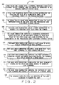
- Figure 2 is a flow chart illustrating a process for rendering a real-time conformal view of terrain being traversed by a mobile platform utilizing the real-time rendering assist system shown in Figure 1.
- a real-time rendering assist system 10 is provided to render conformal terrain views to pilot displays.
- the conformal view provides an overlay of the actual terrain that a mobile platform is traversing onto what the pilot actually sees through the cockpit windows.
- the real-time rendering assist system 10 provides a perspective view of 3-D terrain in such a way that that terrain is conformal with the real world situation, whereas a perspective view means things are scaled in an appropriate fashion to make them look realistic. Therefore, if a pilot's view of the actual terrain is impaired, e.g. by clouds, fog or darkness, the conformal terrain view will display a graphical rendering of the actual terrain that the pilot can not see.
- the real-time rendering assist system 10 includes an existing onboard computer system (OCS) 14 of a mobile platform 18.
- OCS onboard computer system
- the OCS 14 includes at least one random access memory (RAM) device 22 and least one processing card 26 that is communicatively linked to at least one graphics card 30, via a data bus 32.
- the processing card 26 includes at least one processor 34 and at least one electronic storage device (ESD) 36, for example a second RAM device.
- ESD electronic storage device
- the OCS 14 is an existing, installed onboard computer system of the mobile platform 18 and the remaining component(s) of the present invention, as described below, are retrofit with the existing installed OCS 14 to provide the methods and system of the present invention.
- the real-time rendering assist system 10 additionally includes an external removable mass data storage device (ERMDSD) 38 that is adapted to removably connect with the OCS 14 to establish a communication link with the processing card 26.
- ERMDSD 38 can be any suitable computer readable, removable, mass storage medium for electronically storing data, for example a solid state mass storage device such as a PCMCIA card.
- the processor 34 is adapted to execute all functions of the processing card 32. For example, the processor 34 is adapted to access the RAM 32 and the ESD 36 and to execute a real-time rendering assist application (RTRAA) 42 stored on the processing card ESD 36.
- RTRAA real-time rendering assist application
- the processor 34 accesses the RAM device 22 via a PCI bus (not shown) and is divided into a plurality of windows, e.g. 256 MB windows, that can be used one at a time and do not slide.
- the graphics card 30 includes an electronic storage device 46, e.g. a third RAM device, and a processor 50 adapted to render tessellated data stored on the graphics card ESD 46, as described below.
- FIG 2 is a flow chart 100 illustrating a method for providing a real-time conformal view of terrain being traversed by the mobile platform 18 to a pilot of the mobile platform 18 utilizing the real-time rendering assist system 10, shown in Figure 1.
- digital terrain elevation data DTED
- at least one non-graphics processing card tessellates the DTED data and communicates the tessellated data to a graphics card. That is, the DTED data is 'pre-tessellated' and transmitted to the graphics card such that the graphics card does not perform any tessellation, but merely renders the pre-tessellated data.
- DTED is a collection of tiles representing areas of a mathematical representation of a terrestrial body, such as the earth.
- the tiles are stored as files in a pre-defined directory structure and are generally accessed by latitude and longitude.
- Each tile covers a one degree square area bounded by whole degree latitude and longitude lines and referenced by its southwest corner.
- a tile contains a discrete number of grid points whose value is the elevation in meters at the corresponding location. Rows correspond to longitude, ascending from west to east and columns correspond to latitude, ascending from south to north.
- Grid intervals are defined in terms of arc seconds, and the number of points in a row varies with latitude, due to the fact that longitudinal lines converge at the poles.
- a Level 1 DTED tile contains elevations spaced 3 arc seconds apart ( ⁇ 100 m).
- a tile located within the +/- 0-50 degrees latitude band contains 1201 x 1201 posts, but a tile located between +/- 50-70 degrees contains only 601 x 1201 posts.
- the DTED is transferred from a storage media, e.g. data CDs, zip drive, thumb drive, wired or wireless download from remote server system, to a large external storage device the ERMDSD 38 and the ERMDSD 38 is connected to the OCS 14.
- the RTRAA 42 stored on the processing card ESD 42, is executed by the processing card processor 34 to determine the location and size of the area to be rendered based on the current view frustum and related parameters such as mobile platform position, heading velocity or head motion for a helmet mounted display on which the conformal view will be rendered, as indicated at 104.
- the area to be rendered is the area of the terrestrial body, e.g. earth, to be traversed (ATBT) by the mobile platform 18.
- the RTRAA 42 calls a base mesh subroutine included in the RTRAA 42 to load the data representative of the desired area to be rendered into the processing card ESD 36, based on latitude, longitude and elevation of the mobile platform, as indicated at 106.
- the base mesh routine then calls a chunk subroutine included in the RTRAA 42 to request the required DTED tiles, as indicated at 108.
- the DTED tiles are data packets having sizes that are not easily interpretable or manageable by the graphics card. Therefore, the chunk subroutine locates the desired DTED tiles and dynamically repackages or reformats the DTED tiles into DTED chunks representative of the desired area to be rendered that are easily interpretable/manageable by the graphics card.
- the chunk subroutine calls a DTED subroutine included in the RTRAA 42 to request the required DTED tiles.
- the DTED subroutine loads the required DTED tiles from the ERMDSD 38 and returns pointers for the requested tiles to the chunk subroutine.
- the chunk subroutine then repackages/reformats the underlying DTED tiles into the requested DTED chunks that are easily interpretable/manageable by the graphics card.
- the chunk subroutine computes a geocentric coordinate vertex for each data point/grid in the DTED chunk and loads the DTED chunk into the base mesh subroutine, as indicated at 110. Particularly, the chunk subroutine utilizes the latitude, longitude and elevation data of the mobile platform 18 to compute the geocentric coordinate vertices relative to the southwest corner of each data point/grid in the DTED chunk. The chunk subroutine loads the DTED chunk into the base mesh subroutine by returning a pointer to the DTED chunk, now consisting of geocentric coordinate vertex data, to the base mesh subroutine.
- the unit of drawing in graphics hardware is generally the triangle.
- the base mesh subroutine overlays each DTED chunk with one diamond, known as the root diamond, as indicated at 112. That is, the base mesh routine activates the corresponding root diamond.
- Each root diamond has five vertices, one at each of four corners of the data chunk and one in the center.
- the base mesh subroutine creates a base mesh that ties the root diamonds to their underlying data, as indicated at 114.
- the base mesh includes a matrix of root diamonds that represent terrain data covering the area of the terrestrial body's surface desired to be rendered.
- Each rendered view of DTED has its own base mesh, which is the mechanism that allows multiple views of DTED at potentially different points.
- the base mesh subroutine may load one or more root diamonds into the base mesh, depending on the size of the viewable area, e.g. the ATBT, but only one is considered the base diamond.
- the base diamond is used to set the current origin of the base mesh and has priority over the other root diamonds during tessellation.
- the base mesh subroutine then computes a bounding sphere and error value for each root diamond, places the root diamond on a split queue 54 or merge queue 58 in the RAM device 22, and returns a pointer for the root diamond to the RTRAA 42, as indicated at 116.
- the bounding sphere is the smallest sphere that encompasses the entire diamond and is used to determine whether or not the diamond is within the view frustum.
- the error value takes into account the difference between an actual height value of each root diamond and an interpolated height value of each root diamond calculated using the values of two corners of each respective root diamond.
- the error value also takes into account the width of each diamond and is used to decide whether or not a diamond should be split or merged, as described below.
- the split and merge queues 54 and 58 are used to facilitate the splitting and merging of diamonds.
- the process of representing a portion of the terrestrial body's, e.g. earth's, surface as a contiguous mesh of triangles is called tessellation.
- the base mesh subroutine tessellates each diamond stored in the split and merge queues 54 or 58, as indicated at 118.
- the diamond(s) is/are recursively split into four child diamonds, so that each diamond has two parents and four children.
- Each diamond is given a relative priority, which takes into account such things as whether or not it is in view, its size relative to the underlying data, and the differences between elevations within the diamond.
- the diamond is then placed on the appropriate split or merge queue 54 or 58.
- the base mesh subroutine employs a real-time optimally adapting meshes (ROAM) algorithm to compute the bounding sphere and error values, place the root diamond on a split queue 54 or merge queue 58, and perform the tessellation process.
- ROAM real-time optimally adapting meshes
- the base mesh subroutine can employ any other algorithm suitable to tessellate, i.e. split, the diamonds without departing from the scope of the present invention.
- the diamonds are split until they are the same granularity as the underlying data. That is, the diamonds are split until the smallest diamond, called a leaf diamond, has one grid point at each corner and only one in the center. Only leaf diamonds, i.e. diamonds that are not split, are actually rendered by the graphics card 30. Diamonds may also be merged back together, for example to represent an expanse of flat terrain or because they are no longer in view.
- the tessellation process determines which diamonds should be split and which diamonds should be merged together because they may be too small or detailed. If the diamond is too small such that the diamond would not be seen on the screen, the RTRAA 42 merges the small diamonds to make a bigger diamond.
- the error value is utilized during the tessellation process to determine whether a diamond should be split to provide more detail during the rendering process. For example, if an aircraft is flying over mountainous terrain, there will be a lot of height difference within a diamond. Therefore, the diamond will be split into smaller diamonds to provide more details when the diamonds are rendered by the graphics card 30. The diamonds are split until the resulting diamonds have one grid point at each corner and only one in the center, i.e. leaf diamonds or leaf nodes.
- the base mesh subroutine first determines which diamonds should be culled. Each diamond inherits the state of one of its ancestors, specifically its quad-tree parent. If the parent is completely inside or outside of the frustum, the diamond and all its children are considered to have the same status, and no further processing is necessary. However, if the parent is partially inside the frustum the diamond's bounding sphere must be evaluated. Depending on how its state has changed from frame to frame, the diamond may be placed on the split or merge queue 54 or 58. Once cull flags have been updated and diamonds have been placed on the split or merge queue 54 or 58 as appropriate, the base mesh subroutine updates the priority value for each queued diamond.
- Each diamond's priority is based on its error value and its distance from an eye point of a viewer, e.g. the mobile platform operator. After reprioritizing the queued diamonds, splits and merges are actually performed, starting with the highest priority diamonds. This process continues to add to or reconfigure the base mesh until the maximum leaf diamond count has been reached, or the desired fineness is achieved, or a certain number of diamonds have been processed.
- the base mesh is then traversed to find all its leaves, i.e. the diamonds that have no children. Once found, the base mesh subroutine computes the vertices of each leaf diamond's triangles relative to the origin of the base mesh and stores the vertices in a vertex array in the processing card ESD 36, as indicated at 120. When this process is complete, the vertex array is ready to be rendered by the graphics card 30. In various embodiments, the vertex array is transferred from the processing card ESD 36 to memory on the graphics card ESD 46 in segments or pieces. That is, the RTRAA 42 breaks the vertex array into several small pieces, e.g. 256 KB, to send the vertex array and reassembles the vertex array on the graphics card ESD 46.
- the process of transferring the vertex array to the graphics card ESD 46 in pieces uses bandwidth of the data bus 32 more efficiently and avoids stalling of the data bus 32. While the RTRAA 42 transfers the vertex array to the graphics card ESD 46, higher priority data transfers are allowed to interrupt the vertex array transfer. In other words, transferring a large vertex array will not lock out the regular transfer of data that may be changing at much higher rates.
- the graphics card 30 executes the rendering application to render the vertex array, as indicated at 122.
- the graphics card processor 50 can render the vertex array using standard OpenGL triangle drawing techniques. Therefore, all the tessellation is performed by the processing card 26. That is, the processing card 26 'pre-tessellates' the DTED and effectively the only processing performed by the graphics card processor 50 is rendering the vertex array, thereby allowing the graphics card 30 to render the desired area to be viewed as quickly as possible.
- the RTRAA provides 3-D terrain rendering and database management on existing low performance hardware, i.e. hardware currently installed on the mobile platform 18, with the performance required for fast-moving displays, e.g. helmet-mounted displays.
- the RTRAA provides data management routines that efficiently move data from storage media to processors on an as-needed basis; data processing routines that provide a highly efficient level of detail control for multiple viewpoints; and rendering routines that allow real-time capability on low-performance hardware platforms.
- the RTRAA provides efficient database management capable of processing several gigabytes of data to generate real-time 3D terrain rendering for fast-moving displays.
- the RTRAA provides such database management and real-time 3D terrain rendering that is capable of maintaining a display update rate of approximately 60 Hz. This means that all processing is generally completed within approximately 16.6667 ms per frame. Due to the large amount of data and the complex processing that needs to be performed for such displays, the real-time render assist system 10 separates the processing of data from the rendering of it.
Landscapes
- Engineering & Computer Science (AREA)
- Physics & Mathematics (AREA)
- Geometry (AREA)
- Software Systems (AREA)
- General Physics & Mathematics (AREA)
- Theoretical Computer Science (AREA)
- Computer Graphics (AREA)
- Remote Sensing (AREA)
- Processing Or Creating Images (AREA)
- Navigation (AREA)
Abstract
Description
- The invention relates generally to mobile platform guidance systems. More particularly, the invention relates to three dimensional (3D) terrain rendering for pilot displays.
- Situation awareness displays, such as helmet-mounted displays, are rapidly becoming required elements of several existing and future mobile platforms and programs. Conformal views of digital terrain data provide a significant increase in almost any situation awareness application. Although several 3D terrain rendering products are available today, they require high-performance rendering hardware not available for flight-worthy applications.
- Providing 3D terrain displays involves not only the rendering algorithms, but also involves managing and moving large amounts of data between storage media and rendering processor memory. Mission requirements typically drive the need for removable storage media, and flight-worthy hardware typically requires this to be solid-state storage. Operational requirements drive the need for multiple simultaneous views of similar or differing geographical areas, as well as overlaying terrain with 2D and 3D graphical symbols depicting pathways, obstacles, threats, flight data, etc.
- However, the pre-existing low-performance embedded hardware platforms, i.e. older technology hardware currently installed on most mobile platforms, are not capable of providing such 3D terrain displays. Generally, to provide such real-time conformal terrain graphics to fast moving helmet mounted displays requires managing several gigabytes of data and updating the display approximately 30-60 times per second. The known pre-existing embedded hardware is not capable of processing such large volumes of data at speeds necessary to provide real-time 3D terrain rendering for fast-moving helmet mounted displays.
- In various embodiments of the present invention, a method for rendering a real-time conformal view of terrestrial body's terrain being traversed by a mobile platform is provided. The method includes storing digital terrain elevation data (DTED) tiles for at least a portion of the terrain of a terrestrial body into an external removable mass data storage device (ERMDSD). The ERMDSD is then connected to an onboard computer system (OCS) of a mobile platform. The OCS comprises embedded mobile platform components that include at least one processing card, at least one random access memory (RAM) device and at least one graphics card. The method additionally includes executing a real-time rendering assist application (RTRAA) stored in the processing card to dynamically repackage the DTED tiles into DTED chunks being representative of an area of the terrestrial body to be traversed (ATBT) by the mobile platform. The RTRAA additionally loads the DTED chunks into an electronic storage device of the processing card. The method further includes executing the RTRAA to create a base mesh of root diamonds representative of the ATBT, the base mesh being stored in the RAM device. Execution of the RTRAA tessellates the root diamonds to create a plurality of leaf diamonds derived from the DTED chunks. Further yet the method includes executing a rendering application included in the graphics card to render the leaf diamonds to generate a real-time conformal view of the ATBT.
- The features, functions, and advantages of the present invention can be achieved independently in various embodiments of the present inventions or may be combined in yet other embodiments.
- The present invention will become more fully understood from the detailed description and accompanying drawings, wherein;
- Figure 1 is a block diagram of a real-time rendering assist system, in accordance with various embodiments of the present invention; and
- Figure 2 is a flow chart illustrating a process for rendering a real-time conformal view of terrain being traversed by a mobile platform utilizing the real-time rendering assist system shown in Figure 1.
- Corresponding reference numerals indicate corresponding parts throughout the several views of drawings.
- The following description of the preferred embodiments is merely exemplary in nature and is in no way intended to limit the invention, its application or uses. Additionally, the advantages provided by the preferred embodiments, as described below, are exemplary in nature and not all preferred embodiments provide the same advantages or the same degree of advantages.
- Referring to Figure 1, in accordance with various embodiments of the present invention, a real-time
rendering assist system 10 is provided to render conformal terrain views to pilot displays. Generally, the conformal view provides an overlay of the actual terrain that a mobile platform is traversing onto what the pilot actually sees through the cockpit windows. There is a one-to-one correspondence with what the pilot sees in the display versus what the pilot sees through the cockpit windows. More particularly, the real-timerendering assist system 10 provides a perspective view of 3-D terrain in such a way that that terrain is conformal with the real world situation, whereas a perspective view means things are scaled in an appropriate fashion to make them look realistic. Therefore, if a pilot's view of the actual terrain is impaired, e.g. by clouds, fog or darkness, the conformal terrain view will display a graphical rendering of the actual terrain that the pilot can not see. - The real-time
rendering assist system 10 includes an existing onboard computer system (OCS) 14 of amobile platform 18. Although themobile platform 18 is illustrated as an aircraft, the invention is not limited to aircraft, but is applicable to all mobile platforms such as aircraft, ships, buses, trains and automobiles. The OCS 14 includes at least one random access memory (RAM)device 22 and least oneprocessing card 26 that is communicatively linked to at least onegraphics card 30, via adata bus 32. Theprocessing card 26 includes at least oneprocessor 34 and at least one electronic storage device (ESD) 36, for example a second RAM device. It should be understood that the OCS 14 and all components of the OCS 14, e.g. the RAM, processing card andgraphics card mobile platform 18 and the remaining component(s) of the present invention, as described below, are retrofit with the existing installed OCS 14 to provide the methods and system of the present invention. - The real-time
rendering assist system 10 additionally includes an external removable mass data storage device (ERMDSD) 38 that is adapted to removably connect with the OCS 14 to establish a communication link with theprocessing card 26. The ERMDSD 38 can be any suitable computer readable, removable, mass storage medium for electronically storing data, for example a solid state mass storage device such as a PCMCIA card. Theprocessor 34 is adapted to execute all functions of theprocessing card 32. For example, theprocessor 34 is adapted to access theRAM 32 and theESD 36 and to execute a real-time rendering assist application (RTRAA) 42 stored on the processing card ESD 36. In various embodiments, theprocessor 34 accesses theRAM device 22 via a PCI bus (not shown) and is divided into a plurality of windows, e.g. 256 MB windows, that can be used one at a time and do not slide. Additionally, thegraphics card 30 includes anelectronic storage device 46, e.g. a third RAM device, and aprocessor 50 adapted to render tessellated data stored on the graphics card ESD 46, as described below. - Figure 2 is a
flow chart 100 illustrating a method for providing a real-time conformal view of terrain being traversed by themobile platform 18 to a pilot of themobile platform 18 utilizing the real-timerendering assist system 10, shown in Figure 1. Generally, to provide the real-time conformal view, digital terrain elevation data (DTED) is loaded into the real-timerendering assist system 10 from a storage media, then at least one non-graphics processing card tessellates the DTED data and communicates the tessellated data to a graphics card. That is, the DTED data is 'pre-tessellated' and transmitted to the graphics card such that the graphics card does not perform any tessellation, but merely renders the pre-tessellated data. - DTED is a collection of tiles representing areas of a mathematical representation of a terrestrial body, such as the earth. The tiles are stored as files in a pre-defined directory structure and are generally accessed by latitude and longitude. Each tile covers a one degree square area bounded by whole degree latitude and longitude lines and referenced by its southwest corner. A tile contains a discrete number of grid points whose value is the elevation in meters at the corresponding location. Rows correspond to longitude, ascending from west to east and columns correspond to latitude, ascending from south to north. Grid intervals are defined in terms of arc seconds, and the number of points in a row varies with latitude, due to the fact that longitudinal lines converge at the poles. For example, a Level 1 DTED tile contains elevations spaced 3 arc seconds apart (~100 m). A tile located within the +/- 0-50 degrees latitude band contains 1201 x 1201 posts, but a tile located between +/- 50-70 degrees contains only 601 x 1201 posts.
- As illustrated at 102, the DTED is transferred from a storage media, e.g. data CDs, zip drive, thumb drive, wired or wireless download from remote server system, to a large external storage device the ERMDSD 38 and the ERMDSD 38 is connected to the OCS 14. The RTRAA 42, stored on the processing card ESD 42, is executed by the
processing card processor 34 to determine the location and size of the area to be rendered based on the current view frustum and related parameters such as mobile platform position, heading velocity or head motion for a helmet mounted display on which the conformal view will be rendered, as indicated at 104. Generally, the area to be rendered is the area of the terrestrial body, e.g. earth, to be traversed (ATBT) by themobile platform 18. The RTRAA 42 calls a base mesh subroutine included in the RTRAA 42 to load the data representative of the desired area to be rendered into the processing card ESD 36, based on latitude, longitude and elevation of the mobile platform, as indicated at 106. - The base mesh routine then calls a chunk subroutine included in the RTRAA 42 to request the required DTED tiles, as indicated at 108. However, the DTED tiles are data packets having sizes that are not easily interpretable or manageable by the graphics card. Therefore, the chunk subroutine locates the desired DTED tiles and dynamically repackages or reformats the DTED tiles into DTED chunks representative of the desired area to be rendered that are easily interpretable/manageable by the graphics card. To locate and repackage the desired DTED tiles the chunk subroutine calls a DTED subroutine included in the
RTRAA 42 to request the required DTED tiles. The DTED subroutine loads the required DTED tiles from the ERMDSD 38 and returns pointers for the requested tiles to the chunk subroutine. The chunk subroutine then repackages/reformats the underlying DTED tiles into the requested DTED chunks that are easily interpretable/manageable by the graphics card. - The chunk subroutine computes a geocentric coordinate vertex for each data point/grid in the DTED chunk and loads the DTED chunk into the base mesh subroutine, as indicated at 110. Particularly, the chunk subroutine utilizes the latitude, longitude and elevation data of the
mobile platform 18 to compute the geocentric coordinate vertices relative to the southwest corner of each data point/grid in the DTED chunk. The chunk subroutine loads the DTED chunk into the base mesh subroutine by returning a pointer to the DTED chunk, now consisting of geocentric coordinate vertex data, to the base mesh subroutine. The unit of drawing in graphics hardware is generally the triangle. In terms of processing, however, work is done on the basis of diamonds that consist of two right-isosceles triangles joined at a common base edge. In accordance with various embodiments of the present invention, the base mesh subroutine overlays each DTED chunk with one diamond, known as the root diamond, as indicated at 112. That is, the base mesh routine activates the corresponding root diamond. Each root diamond has five vertices, one at each of four corners of the data chunk and one in the center. The base mesh subroutine creates a base mesh that ties the root diamonds to their underlying data, as indicated at 114. Thus, the base mesh includes a matrix of root diamonds that represent terrain data covering the area of the terrestrial body's surface desired to be rendered. Each rendered view of DTED has its own base mesh, which is the mechanism that allows multiple views of DTED at potentially different points. The base mesh subroutine may load one or more root diamonds into the base mesh, depending on the size of the viewable area, e.g. the ATBT, but only one is considered the base diamond. The base diamond is used to set the current origin of the base mesh and has priority over the other root diamonds during tessellation. - The base mesh subroutine then computes a bounding sphere and error value for each root diamond, places the root diamond on a
split queue 54 or mergequeue 58 in theRAM device 22, and returns a pointer for the root diamond to theRTRAA 42, as indicated at 116. The bounding sphere is the smallest sphere that encompasses the entire diamond and is used to determine whether or not the diamond is within the view frustum. The error value takes into account the difference between an actual height value of each root diamond and an interpolated height value of each root diamond calculated using the values of two corners of each respective root diamond. The error value also takes into account the width of each diamond and is used to decide whether or not a diamond should be split or merged, as described below. The split and mergequeues - The process of representing a portion of the terrestrial body's, e.g. earth's, surface as a contiguous mesh of triangles is called tessellation. Starting with the root diamond(s), the base mesh subroutine tessellates each diamond stored in the split and merge
queues queue split queue 54 or mergequeue 58, and perform the tessellation process. Alternatively, the base mesh subroutine can employ any other algorithm suitable to tessellate, i.e. split, the diamonds without departing from the scope of the present invention. - The diamonds are split until they are the same granularity as the underlying data. That is, the diamonds are split until the smallest diamond, called a leaf diamond, has one grid point at each corner and only one in the center. Only leaf diamonds, i.e. diamonds that are not split, are actually rendered by the
graphics card 30. Diamonds may also be merged back together, for example to represent an expanse of flat terrain or because they are no longer in view. - Generally, the tessellation process determines which diamonds should be split and which diamonds should be merged together because they may be too small or detailed. If the diamond is too small such that the diamond would not be seen on the screen, the
RTRAA 42 merges the small diamonds to make a bigger diamond. As described above, the error value is utilized during the tessellation process to determine whether a diamond should be split to provide more detail during the rendering process. For example, if an aircraft is flying over mountainous terrain, there will be a lot of height difference within a diamond. Therefore, the diamond will be split into smaller diamonds to provide more details when the diamonds are rendered by thegraphics card 30. The diamonds are split until the resulting diamonds have one grid point at each corner and only one in the center, i.e. leaf diamonds or leaf nodes. - More specifically, during tessellation, the base mesh subroutine first determines which diamonds should be culled. Each diamond inherits the state of one of its ancestors, specifically its quad-tree parent. If the parent is completely inside or outside of the frustum, the diamond and all its children are considered to have the same status, and no further processing is necessary. However, if the parent is partially inside the frustum the diamond's bounding sphere must be evaluated. Depending on how its state has changed from frame to frame, the diamond may be placed on the split or merge
queue queue - The base mesh is then traversed to find all its leaves, i.e. the diamonds that have no children. Once found, the base mesh subroutine computes the vertices of each leaf diamond's triangles relative to the origin of the base mesh and stores the vertices in a vertex array in the
processing card ESD 36, as indicated at 120. When this process is complete, the vertex array is ready to be rendered by thegraphics card 30. In various embodiments, the vertex array is transferred from theprocessing card ESD 36 to memory on thegraphics card ESD 46 in segments or pieces. That is, theRTRAA 42 breaks the vertex array into several small pieces, e.g. 256 KB, to send the vertex array and reassembles the vertex array on thegraphics card ESD 46. The process of transferring the vertex array to thegraphics card ESD 46 in pieces uses bandwidth of thedata bus 32 more efficiently and avoids stalling of thedata bus 32. While theRTRAA 42 transfers the vertex array to thegraphics card ESD 46, higher priority data transfers are allowed to interrupt the vertex array transfer. In other words, transferring a large vertex array will not lock out the regular transfer of data that may be changing at much higher rates. - Once the vertex array has been transferred to the
graphics card ESD 46, thegraphics card 30 executes the rendering application to render the vertex array, as indicated at 122. For example, thegraphics card processor 50 can render the vertex array using standard OpenGL triangle drawing techniques. Therefore, all the tessellation is performed by theprocessing card 26. That is, the processing card 26 'pre-tessellates' the DTED and effectively the only processing performed by thegraphics card processor 50 is rendering the vertex array, thereby allowing thegraphics card 30 to render the desired area to be viewed as quickly as possible. - Thus, the RTRAA provides 3-D terrain rendering and database management on existing low performance hardware, i.e. hardware currently installed on the
mobile platform 18, with the performance required for fast-moving displays, e.g. helmet-mounted displays. Particularly, the RTRAA provides data management routines that efficiently move data from storage media to processors on an as-needed basis; data processing routines that provide a highly efficient level of detail control for multiple viewpoints; and rendering routines that allow real-time capability on low-performance hardware platforms. In various embodiments, the RTRAA provides efficient database management capable of processing several gigabytes of data to generate real-time 3D terrain rendering for fast-moving displays. - More specifically, the RTRAA provides such database management and real-time 3D terrain rendering that is capable of maintaining a display update rate of approximately 60 Hz. This means that all processing is generally completed within approximately 16.6667 ms per frame. Due to the large amount of data and the complex processing that needs to be performed for such displays, the real-time render
assist system 10 separates the processing of data from the rendering of it. - Those skilled in the art can now appreciate from the foregoing description that the broad teachings of the present invention can be implemented in a variety of forms. Therefore, while this invention has been described in connection with particular examples thereof, the true scope of the invention should not be so limited since other modifications will become apparent to the skilled practitioner upon a study of the drawings, specification and following claims.
Claims (22)
- A method for rendering a real-time conformal view of terrestrial body's terrain being traversed by a mobile platform, said method comprising:determining an area of a terrestrial body to be traversed (ATBT) by a mobile platform;tessellating digital terrain elevation data (DTED) representative of a terrain of the ATBT using a processing card communicatively connected to an independent and separate graphics card, the processing card and the graphics card being embedded components of an onboard computer system (OCS) of the mobile platform; andrendering the tessellated DTED using the graphics card to provide a conformal view of the ATBT terrain as the mobile platform traverses the ATBT.
- The method of Claim 1, further comprises storing DTED of at least a portion of the terrain of the terrestrial body into an external removable mass data storage device (ERMDSD) connectable to the OCS.
- The method of Claim 2, wherein tessellating the DTED comprises executing a base mesh routine to load the DTED representative of the ATBT into a first electronic storage device that is independent and separate from graphics card.
- The method of Claim 3, wherein tessellating the DTED comprises executing the base mesh routine to tessellated the DTED loaded into the first electronic storage device and load the tessellated data into a second electronic storage device included in the graphics card.
- A system for rendering a real-time conformal view of terrestrial body's terrain being traversed by a mobile platform, said system comprising:an onboard computer system (OCS) comprising embedded mobile platform components including at least one processing card, at least random access memory (RAM) device and at least one graphics card,an external removable mass data storage device (ERMDSD) connectable to the OCS and adapted for storing digital terrain elevation data (DTED) tiles for at least a portion of a terrain of a terrestrial body;wherein the processing card comprises a processor adapted to execute a real-time rendering assist application (RTRAA) stored in the processing card to:dynamically repackage the DTED tiles into DETD chunks representative of an area of the terrestrial body to be traversed (ATBT) by the mobile platform;load the DTED chunks into an electronic storage device of the processing card;create a base mesh of root diamonds representative of the ATBT; andtessellate the root diamonds to create a plurality of leaf diamonds, the root diamonds derived from the DTED chunks and the base mesh being stored in the RAM device; andthe graphics card comprises a processor adapted to execute a rendering application included in the graphics card to render the leaf diamonds to generate a real-time conformal view of the ATBT.
- The system of Claim 5, wherein the processing card processor is further adapted to execute a DTED subroutine of the RTRAA to load the required DTED tiles from the ERMDSD by returning pointers for the requested DETD tiles to a chunk subroutine of the RTRAA.
- The system of Claim 5, wherein the processing card processor is further adapted to execute a chunk subroutine of the RTRAA to dynamically repackage the DTED tiles into the DTED chunks that are interpretable by a rendering application of the graphics card.
- The system of Claim 5, wherein the processing card processor is further adapted execute a base mesh subroutine of the RTRAA to overlay each DTED chunk with a root diamond.
- The system of Claim 5, wherein the processing card processor is further adapted execute a base mesh subroutine of the RTRAA to compute a bounding sphere and an error value for each root diamond.
- The system of Claim 9, wherein the processing card processor is further adapted execute the base mesh subroutine to place each root diamond into one of a split queue and a merge queue in the RAM device based on the respective bounding sphere and error value for each root diamond.
- The system of Claim 5, wherein the processing card processor is further adapted execute a base mesh subroutine of the RTRAA to compute vertices for each leaf diamond and create a vertex array therefrom that is stored in processing card electronic storage device.
- The system of Claim 11, wherein the processing card processor is further adapted transfer the vertex array from the processing card electronic storage device to an electronic storage device of the graphics card in segments.
- The system of Claim 12, wherein the graphic card processor is further adapted executing the rendering application to render the vertex array stored in the graphics card electronic storage device to generate the real-time conformal view of the ATBT.
- A method for rendering a real-time conformal view of terrestrial body's terrain being traversed by a mobile platform, said method comprising:storing digital terrain elevation data (DTED) tiles for at least a portion of a terrain of a terrestrial body into an external removable mass data storage device (ERMDSD) connectable to an onboard computer system (OCS) of a mobile platform, the OCS comprising embedded mobile platform components including at least one processing card, at least one random access memory (RAM) device and at least one graphics card;executing a real-time rendering assist application (RTRAA) stored in the processing card to dynamically repackage the DTED tiles into DETD chunks representative of an area of the terrestrial body to be traversed (ATBT) by the mobile platform and load the DTED chunks into an electronic storage device of the processing card;executing the RTRAA to create a base mesh of root diamonds representative of the ATBT and tessellate the root diamonds to create a plurality of leaf diamonds, the root diamonds derived from the DTED chunks and the base mesh being stored in the RAM device;executing a rendering application included in the graphics card to render the leaf diamonds to generate a real-time conformal view of the ATBT.
- The method of Claim 14, wherein executing the RTRAA to dynamically repackage the DTED tiles comprises executing a DTED subroutine of the RTRAA to load the required DTED tiles from the ERMDSD by returning pointers for the requested DETD tiles to a chunk subroutine of the RTRAA.
- The method of Claim 14, wherein executing the RTRAA to dynamically repackage the DTED tiles further comprises executing a chunk subroutine of the RTRAA to dynamically repackage the DTED tiles into the DTED chunks that are interpretable by a rendering application of the graphics card.
- The method of Claim 14, wherein executing RTRAA to create the base mesh of root diamonds comprises executing a base mesh subroutine of the RTRAA to overlay each DTED chunk with a root diamond.
- The method of Claim 14, wherein executing the RTRAA to tessellate the root diamonds comprises executing a base mesh subroutine of the RTRAA to compute a bounding sphere and an error value for each root diamond.
- The method of Claim 18, wherein executing the RTRAA to tessellate the root diamonds further comprises executing the base mesh subroutine to place each root diamond into one of a split queue and a merge queue in the RAM device based on the respective bounding sphere and error value for each root diamond.
- The method of Claim 14, wherein executing the RTRAA to tessellate the root diamonds comprises executing a base mesh subroutine of the RTRAA to compute vertices for each leaf diamond and create a vertex array therefrom that is stored in processing card electronic storage device.
- The method of Claim 20, wherein executing the RTRAA to tessellate the root diamonds further comprises transferring the vertex array from the processing card electronic storage device to an electronic storage device of the graphics card in segments.
- The method of Claim 21, wherein executing a rendering application to render the leaf diamonds comprises executing the rendering application to render the vertex array stored in the graphics card electronic storage device to generate the real-time conformal view of the ATBT.
Applications Claiming Priority (1)
| Application Number | Priority Date | Filing Date | Title |
|---|---|---|---|
| US11/191,621 US7612775B2 (en) | 2005-07-28 | 2005-07-28 | Real-time conformal terrain rendering |
Publications (3)
| Publication Number | Publication Date |
|---|---|
| EP1748392A2 true EP1748392A2 (en) | 2007-01-31 |
| EP1748392A3 EP1748392A3 (en) | 2012-01-11 |
| EP1748392B1 EP1748392B1 (en) | 2018-09-05 |
Family
ID=37087431
Family Applications (1)
| Application Number | Title | Priority Date | Filing Date |
|---|---|---|---|
| EP06253955.6A Not-in-force EP1748392B1 (en) | 2005-07-28 | 2006-07-28 | Real-time conformal terrain rendering |
Country Status (4)
| Country | Link |
|---|---|
| US (1) | US7612775B2 (en) |
| EP (1) | EP1748392B1 (en) |
| JP (1) | JP4953719B2 (en) |
| KR (1) | KR101262380B1 (en) |
Cited By (1)
| Publication number | Priority date | Publication date | Assignee | Title |
|---|---|---|---|---|
| CN105303610A (en) * | 2015-12-05 | 2016-02-03 | 中国航空工业集团公司洛阳电光设备研究所 | Topographic data processing method for drawing airborne topographic three dimensional images |
Families Citing this family (8)
| Publication number | Priority date | Publication date | Assignee | Title |
|---|---|---|---|---|
| AU2008204558A1 (en) * | 2007-01-10 | 2008-07-17 | Tomtom International B.V. | Displaying elevation information from a digital map |
| KR100726031B1 (en) * | 2007-05-02 | 2007-06-08 | 인하대학교 산학협력단 | Terrain Rendering Method Using Cube Mesh Structure |
| US20110050691A1 (en) * | 2008-02-01 | 2011-03-03 | Koshjar Hamedi | Real-time user guided optimization of general 3d data |
| KR101085390B1 (en) * | 2008-04-30 | 2011-11-21 | 주식회사 코아로직 | Image representation method, apparatus for 3D navigation and mobile device including the apparatus |
| US9347792B2 (en) | 2011-10-31 | 2016-05-24 | Honeywell International Inc. | Systems and methods for displaying images with multi-resolution integration |
| GB2536964B (en) * | 2015-04-02 | 2019-12-25 | Ge Aviat Systems Ltd | Avionics display system |
| US11195325B2 (en) | 2015-07-01 | 2021-12-07 | 3D4Medical Limited | Method and apparatus for freeform cutting of digital three dimensional structures |
| US20170336631A1 (en) * | 2016-05-18 | 2017-11-23 | Rockwell Collins, Inc. | Dynamic Vergence for Binocular Display Device |
Citations (1)
| Publication number | Priority date | Publication date | Assignee | Title |
|---|---|---|---|---|
| US20040083038A1 (en) | 2002-10-28 | 2004-04-29 | Gang He | Method for producing 3D perspective view avionics terrain displays |
Family Cites Families (34)
| Publication number | Priority date | Publication date | Assignee | Title |
|---|---|---|---|---|
| US5179638A (en) * | 1990-04-26 | 1993-01-12 | Honeywell Inc. | Method and apparatus for generating a texture mapped perspective view |
| US5949428A (en) * | 1995-08-04 | 1999-09-07 | Microsoft Corporation | Method and apparatus for resolving pixel data in a graphics rendering system |
| US5808617A (en) * | 1995-08-04 | 1998-09-15 | Microsoft Corporation | Method and system for depth complexity reduction in a graphics rendering system |
| US5852443A (en) * | 1995-08-04 | 1998-12-22 | Microsoft Corporation | Method and system for memory decomposition in a graphics rendering system |
| US5990904A (en) * | 1995-08-04 | 1999-11-23 | Microsoft Corporation | Method and system for merging pixel fragments in a graphics rendering system |
| US6359624B1 (en) * | 1996-02-02 | 2002-03-19 | Kabushiki Kaisha Toshiba | Apparatus having graphic processor for high speed performance |
| US6208997B1 (en) * | 1997-10-17 | 2001-03-27 | The Regents Of The University Of California | Rapid production of optimal-quality reduced-resolution representations of very large databases |
| US6856320B1 (en) * | 1997-11-25 | 2005-02-15 | Nvidia U.S. Investment Company | Demand-based memory system for graphics applications |
| US5974423A (en) * | 1998-03-09 | 1999-10-26 | Margolin; Jed | Method for converting a digital elevation database to a polygon database |
| US6342884B1 (en) * | 1999-02-03 | 2002-01-29 | Isurftv | Method and apparatus for using a general three-dimensional (3D) graphics pipeline for cost effective digital image and video editing, transformation, and representation |
| US6317690B1 (en) * | 1999-06-28 | 2001-11-13 | Min-Chung Gia | Path planning, terrain avoidance and situation awareness system for general aviation |
| US6288721B1 (en) * | 1999-07-07 | 2001-09-11 | Litton Systems, Inc. | Rendering process and method for digital map illumination intensity shading |
| US6525726B1 (en) * | 1999-11-02 | 2003-02-25 | Intel Corporation | Method and apparatus for adaptive hierarchical visibility in a tiled three-dimensional graphics architecture |
| US6708090B2 (en) * | 2000-02-29 | 2004-03-16 | Honeywell International Inc. | Method, apparatus and computer program product for managing line-of-sight communications |
| US6674433B1 (en) * | 2000-03-10 | 2004-01-06 | Intel Corporation | Adaptively subdividing a subdivision surface |
| US6567087B1 (en) * | 2000-03-27 | 2003-05-20 | The United States Of America As Represented By The Secretary Of The Army | Method to create a high resolution database |
| US20020060685A1 (en) * | 2000-04-28 | 2002-05-23 | Malcolm Handley | Method, system, and computer program product for managing terrain rendering information |
| US6833797B2 (en) * | 2000-05-26 | 2004-12-21 | Honeywell International Inc. | Method, apparatus and computer program product for displaying terrain in rotary wing aircraft |
| US7245299B2 (en) * | 2003-05-12 | 2007-07-17 | Adrian Sfarti | Bicubic surface real-time tesselation unit |
| US6714196B2 (en) * | 2000-08-18 | 2004-03-30 | Hewlett-Packard Development Company L.P | Method and apparatus for tiled polygon traversal |
| US6597356B1 (en) * | 2000-08-31 | 2003-07-22 | Nvidia Corporation | Integrated tessellator in a graphics processing unit |
| US6600489B2 (en) * | 2000-12-14 | 2003-07-29 | Harris Corporation | System and method of processing digital terrain information |
| US7027046B2 (en) * | 2001-02-09 | 2006-04-11 | Vicarious Visions, Inc. | Method, system, and computer program product for visibility culling of terrain |
| US6954203B2 (en) * | 2001-03-16 | 2005-10-11 | Mitsubishi Electric Research Labs, Inc. | Modeling and combining multiple graphics objects |
| EP1405270A1 (en) * | 2001-07-06 | 2004-04-07 | Goodrich Avionics Systems, Inc. | System and method for synthetic vision terrain display |
| DE60217937T2 (en) * | 2001-07-06 | 2007-11-15 | L-3 Communications Avionics Systems, Inc., Grand Rapids | System and method for generating flight plan data |
| US6985144B2 (en) * | 2001-10-30 | 2006-01-10 | Hewlett-Packard Development Company, L.P. | Layout design apparatus and method for three-dimensional graphical environments |
| US6700573B2 (en) * | 2001-11-07 | 2004-03-02 | Novalogic, Inc. | Method for rendering realistic terrain simulation |
| US7081903B2 (en) * | 2001-12-12 | 2006-07-25 | Hewlett-Packard Development Company, L.P. | Efficient movement of fragment stamp |
| US6862028B2 (en) * | 2002-02-14 | 2005-03-01 | Intel Corporation | Bin pointer and state caching apparatus and method |
| US6980224B2 (en) * | 2002-03-26 | 2005-12-27 | Harris Corporation | Efficient digital map overlays |
| US7239311B2 (en) * | 2002-09-26 | 2007-07-03 | The United States Government As Represented By The Secretary Of The Navy | Global visualization process (GVP) and system for implementing a GVP |
| US7436405B2 (en) * | 2004-05-14 | 2008-10-14 | Microsoft Corporation | Terrain rendering using nested regular grids |
| US8207966B2 (en) * | 2004-05-26 | 2012-06-26 | Sony Online Entertainment Llc | Terrain editor tool for rule-based procedural terrain generation |
-
2005
- 2005-07-28 US US11/191,621 patent/US7612775B2/en not_active Expired - Fee Related
-
2006
- 2006-07-27 JP JP2006205113A patent/JP4953719B2/en not_active Expired - Fee Related
- 2006-07-28 EP EP06253955.6A patent/EP1748392B1/en not_active Not-in-force
- 2006-07-28 KR KR1020060071449A patent/KR101262380B1/en not_active Expired - Fee Related
Patent Citations (1)
| Publication number | Priority date | Publication date | Assignee | Title |
|---|---|---|---|---|
| US20040083038A1 (en) | 2002-10-28 | 2004-04-29 | Gang He | Method for producing 3D perspective view avionics terrain displays |
Non-Patent Citations (1)
| Title |
|---|
| "Real-Time Optimal Adaptation for Planetary Geometry and Texture: 4-8 Tile Hierarchies", IEEE TRANSACTIONS ON VISUALISATION AND COMPUTER GRAPHICS, IEEE SERVICE CENTER, LOS ALAMITOS, CA, USA, vol. 11, no. 4, 1 July 2005 (2005-07-01), pages 355 - 368 |
Cited By (2)
| Publication number | Priority date | Publication date | Assignee | Title |
|---|---|---|---|---|
| CN105303610A (en) * | 2015-12-05 | 2016-02-03 | 中国航空工业集团公司洛阳电光设备研究所 | Topographic data processing method for drawing airborne topographic three dimensional images |
| CN105303610B (en) * | 2015-12-05 | 2018-08-17 | 中国航空工业集团公司洛阳电光设备研究所 | A kind of topographic data processing method drawn for airborne profile 3-D view |
Also Published As
| Publication number | Publication date |
|---|---|
| US7612775B2 (en) | 2009-11-03 |
| KR20070015072A (en) | 2007-02-01 |
| JP2007052775A (en) | 2007-03-01 |
| US20070024616A1 (en) | 2007-02-01 |
| EP1748392A3 (en) | 2012-01-11 |
| JP4953719B2 (en) | 2012-06-13 |
| KR101262380B1 (en) | 2013-05-08 |
| EP1748392B1 (en) | 2018-09-05 |
Similar Documents
| Publication | Publication Date | Title |
|---|---|---|
| US7239311B2 (en) | Global visualization process (GVP) and system for implementing a GVP | |
| CN111784833B (en) | Flood evolution situation three-dimensional dynamic visualization display method based on WebGL | |
| US9626790B1 (en) | View-dependent textures for interactive geographic information system | |
| CN113516769B (en) | Virtual reality three-dimensional scene loading and rendering method and device and terminal equipment | |
| EP3170151B1 (en) | Blending between street view and earth view | |
| CA2651908C (en) | Method and system for generating an image-textured digital surface model (dsm) for a geographical area of interest | |
| EP2697766B1 (en) | Integrating maps and street views | |
| CN110347769A (en) | Processing method, device, equipment and the storage medium of multi-layer map tile | |
| US8059121B2 (en) | Method and aircraft display system for generating three dimensional image | |
| CN111798364B (en) | Panoramic prebaking-based quick rendering method and visual imaging system | |
| CN115690336B (en) | Satellite beam coverage area visualization method, server and storage medium | |
| KR101405891B1 (en) | Reality display system of air inteligence and method thereof | |
| US7612775B2 (en) | Real-time conformal terrain rendering | |
| CN109671150A (en) | Airport Earthwork calculation method based on digital earth | |
| CN114140593A (en) | Digital earth and panorama fusion display method and device | |
| US10262631B1 (en) | Large scale highly detailed model review using augmented reality | |
| US20190072407A1 (en) | Interactive Geo-Contextual Navigation Tool | |
| US10304242B1 (en) | Transparent display terrain representation systems and methods | |
| CN107610233A (en) | A kind of simulating scenes construction method based on outdoor scene | |
| CN110852952A (en) | GPU-based large-scale terrain real-time rendering method | |
| CN111433822B (en) | Planet-scale positioning of augmented reality content | |
| US20170228926A1 (en) | Determining Two-Dimensional Images Using Three-Dimensional Models | |
| CN111210515A (en) | Airborne synthetic vision system based on terrain real-time rendering | |
| CN115221263B (en) | Terrain preloading method and system based on route | |
| Hansen et al. | Real-time synthetic vision cockpit display for general aviation |
Legal Events
| Date | Code | Title | Description |
|---|---|---|---|
| PUAI | Public reference made under article 153(3) epc to a published international application that has entered the european phase |
Free format text: ORIGINAL CODE: 0009012 |
|
| 17P | Request for examination filed |
Effective date: 20060807 |
|
| AK | Designated contracting states |
Kind code of ref document: A2 Designated state(s): AT BE BG CH CY CZ DE DK EE ES FI FR GB GR HU IE IS IT LI LT LU LV MC NL PL PT RO SE SI SK TR |
|
| AX | Request for extension of the european patent |
Extension state: AL BA HR MK YU |
|
| PUAL | Search report despatched |
Free format text: ORIGINAL CODE: 0009013 |
|
| AK | Designated contracting states |
Kind code of ref document: A3 Designated state(s): AT BE BG CH CY CZ DE DK EE ES FI FR GB GR HU IE IS IT LI LT LU LV MC NL PL PT RO SE SI SK TR |
|
| AX | Request for extension of the european patent |
Extension state: AL BA HR MK RS |
|
| RIC1 | Information provided on ipc code assigned before grant |
Ipc: G06T 17/00 20060101ALI20111202BHEP Ipc: G06T 15/00 20110101AFI20111202BHEP Ipc: G06T 17/20 20060101ALN20111202BHEP Ipc: G01C 21/00 20060101ALN20111202BHEP |
|
| AKX | Designation fees paid |
Designated state(s): AT BE BG CH CY CZ DE DK EE ES FI FR GB GR HU IE IS IT LI LT LU LV MC NL PL PT RO SE SI SK TR |
|
| 17Q | First examination report despatched |
Effective date: 20121128 |
|
| GRAP | Despatch of communication of intention to grant a patent |
Free format text: ORIGINAL CODE: EPIDOSNIGR1 |
|
| STAA | Information on the status of an ep patent application or granted ep patent |
Free format text: STATUS: GRANT OF PATENT IS INTENDED |
|
| RIC1 | Information provided on ipc code assigned before grant |
Ipc: G06T 15/00 20110101AFI20171213BHEP Ipc: G01C 21/00 20060101ALN20171213BHEP Ipc: G06T 17/20 20060101ALN20171213BHEP Ipc: G06T 17/00 20060101ALI20171213BHEP |
|
| INTG | Intention to grant announced |
Effective date: 20180104 |
|
| GRAJ | Information related to disapproval of communication of intention to grant by the applicant or resumption of examination proceedings by the epo deleted |
Free format text: ORIGINAL CODE: EPIDOSDIGR1 |
|
| STAA | Information on the status of an ep patent application or granted ep patent |
Free format text: STATUS: EXAMINATION IS IN PROGRESS |
|
| REG | Reference to a national code |
Ref country code: DE Ref legal event code: R079 Ref document number: 602006056243 Country of ref document: DE Free format text: PREVIOUS MAIN CLASS: G06T0017500000 Ipc: G06T0015000000 |
|
| GRAP | Despatch of communication of intention to grant a patent |
Free format text: ORIGINAL CODE: EPIDOSNIGR1 |
|
| STAA | Information on the status of an ep patent application or granted ep patent |
Free format text: STATUS: GRANT OF PATENT IS INTENDED |
|
| INTC | Intention to grant announced (deleted) | ||
| RIC1 | Information provided on ipc code assigned before grant |
Ipc: G06T 15/00 20060101AFI20180301BHEP Ipc: G06T 17/20 20060101ALN20180301BHEP Ipc: G06T 17/00 20060101ALI20180301BHEP Ipc: G01C 21/00 20060101ALN20180301BHEP |
|
| INTG | Intention to grant announced |
Effective date: 20180320 |
|
| GRAS | Grant fee paid |
Free format text: ORIGINAL CODE: EPIDOSNIGR3 |
|
| GRAA | (expected) grant |
Free format text: ORIGINAL CODE: 0009210 |
|
| STAA | Information on the status of an ep patent application or granted ep patent |
Free format text: STATUS: THE PATENT HAS BEEN GRANTED |
|
| AK | Designated contracting states |
Kind code of ref document: B1 Designated state(s): AT BE BG CH CY CZ DE DK EE ES FI FR GB GR HU IE IS IT LI LT LU LV MC NL PL PT RO SE SI SK TR |
|
| REG | Reference to a national code |
Ref country code: GB Ref legal event code: FG4D |
|
| REG | Reference to a national code |
Ref country code: CH Ref legal event code: EP |
|
| REG | Reference to a national code |
Ref country code: AT Ref legal event code: REF Ref document number: 1038728 Country of ref document: AT Kind code of ref document: T Effective date: 20180915 |
|
| REG | Reference to a national code |
Ref country code: IE Ref legal event code: FG4D |
|
| REG | Reference to a national code |
Ref country code: DE Ref legal event code: R096 Ref document number: 602006056243 Country of ref document: DE |
|
| REG | Reference to a national code |
Ref country code: NL Ref legal event code: MP Effective date: 20180905 |
|
| REG | Reference to a national code |
Ref country code: LT Ref legal event code: MG4D |
|
| PG25 | Lapsed in a contracting state [announced via postgrant information from national office to epo] |
Ref country code: SE Free format text: LAPSE BECAUSE OF FAILURE TO SUBMIT A TRANSLATION OF THE DESCRIPTION OR TO PAY THE FEE WITHIN THE PRESCRIBED TIME-LIMIT Effective date: 20180905 Ref country code: GR Free format text: LAPSE BECAUSE OF FAILURE TO SUBMIT A TRANSLATION OF THE DESCRIPTION OR TO PAY THE FEE WITHIN THE PRESCRIBED TIME-LIMIT Effective date: 20181206 Ref country code: FI Free format text: LAPSE BECAUSE OF FAILURE TO SUBMIT A TRANSLATION OF THE DESCRIPTION OR TO PAY THE FEE WITHIN THE PRESCRIBED TIME-LIMIT Effective date: 20180905 Ref country code: LT Free format text: LAPSE BECAUSE OF FAILURE TO SUBMIT A TRANSLATION OF THE DESCRIPTION OR TO PAY THE FEE WITHIN THE PRESCRIBED TIME-LIMIT Effective date: 20180905 Ref country code: BG Free format text: LAPSE BECAUSE OF FAILURE TO SUBMIT A TRANSLATION OF THE DESCRIPTION OR TO PAY THE FEE WITHIN THE PRESCRIBED TIME-LIMIT Effective date: 20181205 |
|
| REG | Reference to a national code |
Ref country code: AT Ref legal event code: MK05 Ref document number: 1038728 Country of ref document: AT Kind code of ref document: T Effective date: 20180905 |
|
| PG25 | Lapsed in a contracting state [announced via postgrant information from national office to epo] |
Ref country code: LV Free format text: LAPSE BECAUSE OF FAILURE TO SUBMIT A TRANSLATION OF THE DESCRIPTION OR TO PAY THE FEE WITHIN THE PRESCRIBED TIME-LIMIT Effective date: 20180905 Ref country code: ES Free format text: LAPSE BECAUSE OF FAILURE TO SUBMIT A TRANSLATION OF THE DESCRIPTION OR TO PAY THE FEE WITHIN THE PRESCRIBED TIME-LIMIT Effective date: 20180905 |
|
| PG25 | Lapsed in a contracting state [announced via postgrant information from national office to epo] |
Ref country code: RO Free format text: LAPSE BECAUSE OF FAILURE TO SUBMIT A TRANSLATION OF THE DESCRIPTION OR TO PAY THE FEE WITHIN THE PRESCRIBED TIME-LIMIT Effective date: 20180905 Ref country code: IT Free format text: LAPSE BECAUSE OF FAILURE TO SUBMIT A TRANSLATION OF THE DESCRIPTION OR TO PAY THE FEE WITHIN THE PRESCRIBED TIME-LIMIT Effective date: 20180905 Ref country code: PL Free format text: LAPSE BECAUSE OF FAILURE TO SUBMIT A TRANSLATION OF THE DESCRIPTION OR TO PAY THE FEE WITHIN THE PRESCRIBED TIME-LIMIT Effective date: 20180905 Ref country code: CZ Free format text: LAPSE BECAUSE OF FAILURE TO SUBMIT A TRANSLATION OF THE DESCRIPTION OR TO PAY THE FEE WITHIN THE PRESCRIBED TIME-LIMIT Effective date: 20180905 Ref country code: NL Free format text: LAPSE BECAUSE OF FAILURE TO SUBMIT A TRANSLATION OF THE DESCRIPTION OR TO PAY THE FEE WITHIN THE PRESCRIBED TIME-LIMIT Effective date: 20180905 Ref country code: AT Free format text: LAPSE BECAUSE OF FAILURE TO SUBMIT A TRANSLATION OF THE DESCRIPTION OR TO PAY THE FEE WITHIN THE PRESCRIBED TIME-LIMIT Effective date: 20180905 Ref country code: IS Free format text: LAPSE BECAUSE OF FAILURE TO SUBMIT A TRANSLATION OF THE DESCRIPTION OR TO PAY THE FEE WITHIN THE PRESCRIBED TIME-LIMIT Effective date: 20190105 Ref country code: EE Free format text: LAPSE BECAUSE OF FAILURE TO SUBMIT A TRANSLATION OF THE DESCRIPTION OR TO PAY THE FEE WITHIN THE PRESCRIBED TIME-LIMIT Effective date: 20180905 |
|
| PG25 | Lapsed in a contracting state [announced via postgrant information from national office to epo] |
Ref country code: SK Free format text: LAPSE BECAUSE OF FAILURE TO SUBMIT A TRANSLATION OF THE DESCRIPTION OR TO PAY THE FEE WITHIN THE PRESCRIBED TIME-LIMIT Effective date: 20180905 Ref country code: PT Free format text: LAPSE BECAUSE OF FAILURE TO SUBMIT A TRANSLATION OF THE DESCRIPTION OR TO PAY THE FEE WITHIN THE PRESCRIBED TIME-LIMIT Effective date: 20190105 |
|
| REG | Reference to a national code |
Ref country code: DE Ref legal event code: R097 Ref document number: 602006056243 Country of ref document: DE |
|
| PLBE | No opposition filed within time limit |
Free format text: ORIGINAL CODE: 0009261 |
|
| STAA | Information on the status of an ep patent application or granted ep patent |
Free format text: STATUS: NO OPPOSITION FILED WITHIN TIME LIMIT |
|
| PG25 | Lapsed in a contracting state [announced via postgrant information from national office to epo] |
Ref country code: DK Free format text: LAPSE BECAUSE OF FAILURE TO SUBMIT A TRANSLATION OF THE DESCRIPTION OR TO PAY THE FEE WITHIN THE PRESCRIBED TIME-LIMIT Effective date: 20180905 |
|
| 26N | No opposition filed |
Effective date: 20190606 |
|
| PG25 | Lapsed in a contracting state [announced via postgrant information from national office to epo] |
Ref country code: SI Free format text: LAPSE BECAUSE OF FAILURE TO SUBMIT A TRANSLATION OF THE DESCRIPTION OR TO PAY THE FEE WITHIN THE PRESCRIBED TIME-LIMIT Effective date: 20180905 |
|
| REG | Reference to a national code |
Ref country code: DE Ref legal event code: R082 Ref document number: 602006056243 Country of ref document: DE Representative=s name: MAIER, LL.M., MICHAEL C., DE Ref country code: DE Ref legal event code: R082 Ref document number: 602006056243 Country of ref document: DE Representative=s name: BOULT WADE TENNANT LLP, DE |
|
| REG | Reference to a national code |
Ref country code: DE Ref legal event code: R082 Ref document number: 602006056243 Country of ref document: DE Representative=s name: BOULT WADE TENNANT LLP, DE |
|
| PG25 | Lapsed in a contracting state [announced via postgrant information from national office to epo] |
Ref country code: MC Free format text: LAPSE BECAUSE OF FAILURE TO SUBMIT A TRANSLATION OF THE DESCRIPTION OR TO PAY THE FEE WITHIN THE PRESCRIBED TIME-LIMIT Effective date: 20180905 |
|
| REG | Reference to a national code |
Ref country code: CH Ref legal event code: PL |
|
| PG25 | Lapsed in a contracting state [announced via postgrant information from national office to epo] |
Ref country code: TR Free format text: LAPSE BECAUSE OF FAILURE TO SUBMIT A TRANSLATION OF THE DESCRIPTION OR TO PAY THE FEE WITHIN THE PRESCRIBED TIME-LIMIT Effective date: 20180905 |
|
| REG | Reference to a national code |
Ref country code: BE Ref legal event code: MM Effective date: 20190731 |
|
| PG25 | Lapsed in a contracting state [announced via postgrant information from national office to epo] |
Ref country code: CH Free format text: LAPSE BECAUSE OF NON-PAYMENT OF DUE FEES Effective date: 20190731 Ref country code: LI Free format text: LAPSE BECAUSE OF NON-PAYMENT OF DUE FEES Effective date: 20190731 Ref country code: LU Free format text: LAPSE BECAUSE OF NON-PAYMENT OF DUE FEES Effective date: 20190728 Ref country code: BE Free format text: LAPSE BECAUSE OF NON-PAYMENT OF DUE FEES Effective date: 20190731 |
|
| PG25 | Lapsed in a contracting state [announced via postgrant information from national office to epo] |
Ref country code: IE Free format text: LAPSE BECAUSE OF NON-PAYMENT OF DUE FEES Effective date: 20190728 |
|
| PGFP | Annual fee paid to national office [announced via postgrant information from national office to epo] |
Ref country code: FR Payment date: 20200728 Year of fee payment: 15 Ref country code: GB Payment date: 20200727 Year of fee payment: 15 Ref country code: DE Payment date: 20200729 Year of fee payment: 15 |
|
| PG25 | Lapsed in a contracting state [announced via postgrant information from national office to epo] |
Ref country code: CY Free format text: LAPSE BECAUSE OF FAILURE TO SUBMIT A TRANSLATION OF THE DESCRIPTION OR TO PAY THE FEE WITHIN THE PRESCRIBED TIME-LIMIT Effective date: 20180905 |
|
| PG25 | Lapsed in a contracting state [announced via postgrant information from national office to epo] |
Ref country code: HU Free format text: LAPSE BECAUSE OF FAILURE TO SUBMIT A TRANSLATION OF THE DESCRIPTION OR TO PAY THE FEE WITHIN THE PRESCRIBED TIME-LIMIT; INVALID AB INITIO Effective date: 20060728 |
|
| REG | Reference to a national code |
Ref country code: DE Ref legal event code: R119 Ref document number: 602006056243 Country of ref document: DE |
|
| GBPC | Gb: european patent ceased through non-payment of renewal fee |
Effective date: 20210728 |
|
| PG25 | Lapsed in a contracting state [announced via postgrant information from national office to epo] |
Ref country code: GB Free format text: LAPSE BECAUSE OF NON-PAYMENT OF DUE FEES Effective date: 20210728 Ref country code: DE Free format text: LAPSE BECAUSE OF NON-PAYMENT OF DUE FEES Effective date: 20220201 |
|
| PG25 | Lapsed in a contracting state [announced via postgrant information from national office to epo] |
Ref country code: FR Free format text: LAPSE BECAUSE OF NON-PAYMENT OF DUE FEES Effective date: 20210731 |