EP1748380A2 - Memory card adaptor - Google Patents
Memory card adaptor Download PDFInfo
- Publication number
- EP1748380A2 EP1748380A2 EP06014151A EP06014151A EP1748380A2 EP 1748380 A2 EP1748380 A2 EP 1748380A2 EP 06014151 A EP06014151 A EP 06014151A EP 06014151 A EP06014151 A EP 06014151A EP 1748380 A2 EP1748380 A2 EP 1748380A2
- Authority
- EP
- European Patent Office
- Prior art keywords
- card
- memory card
- memory
- edge
- wall
- Prior art date
- Legal status (The legal status is an assumption and is not a legal conclusion. Google has not performed a legal analysis and makes no representation as to the accuracy of the status listed.)
- Withdrawn
Links
Images







Classifications
-
- G—PHYSICS
- G06—COMPUTING OR CALCULATING; COUNTING
- G06K—GRAPHICAL DATA READING; PRESENTATION OF DATA; RECORD CARRIERS; HANDLING RECORD CARRIERS
- G06K19/00—Record carriers for use with machines and with at least a part designed to carry digital markings
- G06K19/06—Record carriers for use with machines and with at least a part designed to carry digital markings characterised by the kind of the digital marking, e.g. shape, nature, code
- G06K19/067—Record carriers with conductive marks, printed circuits or semiconductor circuit elements, e.g. credit or identity cards also with resonating or responding marks without active components
- G06K19/07—Record carriers with conductive marks, printed circuits or semiconductor circuit elements, e.g. credit or identity cards also with resonating or responding marks without active components with integrated circuit chips
- G06K19/077—Constructional details, e.g. mounting of circuits in the carrier
-
- G—PHYSICS
- G06—COMPUTING OR CALCULATING; COUNTING
- G06K—GRAPHICAL DATA READING; PRESENTATION OF DATA; RECORD CARRIERS; HANDLING RECORD CARRIERS
- G06K19/00—Record carriers for use with machines and with at least a part designed to carry digital markings
- G06K19/06—Record carriers for use with machines and with at least a part designed to carry digital markings characterised by the kind of the digital marking, e.g. shape, nature, code
- G06K19/067—Record carriers with conductive marks, printed circuits or semiconductor circuit elements, e.g. credit or identity cards also with resonating or responding marks without active components
- G06K19/07—Record carriers with conductive marks, printed circuits or semiconductor circuit elements, e.g. credit or identity cards also with resonating or responding marks without active components with integrated circuit chips
-
- G—PHYSICS
- G06—COMPUTING OR CALCULATING; COUNTING
- G06K—GRAPHICAL DATA READING; PRESENTATION OF DATA; RECORD CARRIERS; HANDLING RECORD CARRIERS
- G06K19/00—Record carriers for use with machines and with at least a part designed to carry digital markings
-
- G—PHYSICS
- G06—COMPUTING OR CALCULATING; COUNTING
- G06K—GRAPHICAL DATA READING; PRESENTATION OF DATA; RECORD CARRIERS; HANDLING RECORD CARRIERS
- G06K19/00—Record carriers for use with machines and with at least a part designed to carry digital markings
- G06K19/06—Record carriers for use with machines and with at least a part designed to carry digital markings characterised by the kind of the digital marking, e.g. shape, nature, code
- G06K19/067—Record carriers with conductive marks, printed circuits or semiconductor circuit elements, e.g. credit or identity cards also with resonating or responding marks without active components
- G06K19/07—Record carriers with conductive marks, printed circuits or semiconductor circuit elements, e.g. credit or identity cards also with resonating or responding marks without active components with integrated circuit chips
- G06K19/077—Constructional details, e.g. mounting of circuits in the carrier
- G06K19/07737—Constructional details, e.g. mounting of circuits in the carrier the record carrier consisting of two or more mechanically separable parts
- G06K19/07739—Constructional details, e.g. mounting of circuits in the carrier the record carrier consisting of two or more mechanically separable parts comprising a first part capable of functioning as a record carrier on its own and a second part being only functional as a form factor changing part, e.g. SIM cards type ID 0001, removably attached to a regular smart card form factor
-
- Y—GENERAL TAGGING OF NEW TECHNOLOGICAL DEVELOPMENTS; GENERAL TAGGING OF CROSS-SECTIONAL TECHNOLOGIES SPANNING OVER SEVERAL SECTIONS OF THE IPC; TECHNICAL SUBJECTS COVERED BY FORMER USPC CROSS-REFERENCE ART COLLECTIONS [XRACs] AND DIGESTS
- Y10—TECHNICAL SUBJECTS COVERED BY FORMER USPC
- Y10S—TECHNICAL SUBJECTS COVERED BY FORMER USPC CROSS-REFERENCE ART COLLECTIONS [XRACs] AND DIGESTS
- Y10S439/00—Electrical connectors
- Y10S439/945—Adapter for pcb or cartridge
Definitions
- the present invention contains subject matter related to Japanese Patent Application JP 2005-215965 filed in the Japanese Patent Office on July 26, 2005 , the entire contents of which being incorporated herein by reference.
- the present invention relates to a card tray to which a memory card is mounted.
- Memory cards including a writable flash memory are being marketed so as to be used for writing data in and reading data from the flash memory.
- Such a memory card is typically mounted in the card slot (connector) of an external apparatus such as personal computer or portable telephone set so as to be used for writing data in and reading data from the flash memory of the memory card.
- Known memory cards include Memory Sticks (Registered Trademark, available from Sony Corporation), Multi Media Cards (MMC: Registered Trademark, available from Infineon Technologies AG) and SD Cards (Registered Trademark, available from Matsushita Electric Industrial Co., Ltd., Toshiba Corporation and SanDisk, Inc.).
- MMC Multi Media Cards
- SD Cards Registered Trademark, available from Matsushita Electric Industrial Co., Ltd., Toshiba Corporation and SanDisk, Inc.
- the above listed known memory cards are manufactured according to different sets of product specifications that differ from each other in terms of external dimensions, outer profiles, interfaces to be used for data communications with external apparatus including standards defming the type and the number of signals for data communications and the sequence of data communications.
- any single card slot for receiving a memory card is not able to receive memory cards of different types.
- the second memory card can be mounted in the card slot for the first memory card through the memory card adaptor.
- such a memory card adaptor has to include first adaptor side contact pieces to be electrically connected to the signal input/output contact pieces of the second memory card, second adaptor side contact pieces to be electrically connected to the terminals of the card slot and conductors for electrically connecting the first adaptor side contact pieces and the second adaptor side contact pieces in order to electrically connect the signal input/output contact pieces of the second memory card and the terminals of the card slot.
- Such downsized memory cards include TransFlash cards (Registered Trademark, available from SanDisk, Inc.) whose electric specifications are substantially same as those of SD cards.
- memory card adaptors to be used for such downsized memory cards have reduced external dimensions.
- a card tray to be mounted to a memory card that can make the memory card mountable in a card slot for memory cards conforming to standards different from those to which the memory card conforms even the memory card is a downsized one.
- a card tray to be mounted to a second memory card that is mounted to a first memory card, the first memory card having a memory section buried in a rectangular plate-shaped holder having a length and a width dimensionally larger than the thickness thereof and a plurality of contact pieces arranged transversally in array on the surface of the holder, the second memory card having a memory section buried in a rectangular plate-shaped holder smaller than the holder of the first memory card and a plurality of contact pieces arranged transversally in array on the surface of the holder at the same pitch as that of the contact pieces of the first memory card, the card tray including: a thin plate-shaped main body; and an open and recessed mount section formed on one of the major surfaces of the main body to which the holder of the second memory card is mounted; a memory-card-mounted body being formed by mounting the second memory card to the recessed mount section with the surface directed opposite to the recessed mount section, the thickness and the width of the memory-card-mounted body
- the terminals of the card slot are electrically directly connected to the corresponding respective contact pieces of the second memory card.
- the card tray does not have to have any adaptor side contact pieces and conductor members and hence it is possible to make the external dimensions of the card tray agree with those of the downsized first memory card so that the second memory card can be mounted in the card slot for receiving the first memory card by mounting it to a card tray and forming a memory-card-mounted body.
- FIG 1 is a schematic perspective view of a first memory card 100.
- FIG 2A is a schematic plan view of the first memory card 100
- FIG 2B is a schematic cross sectional view of the first memory card 100.
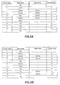
- FIG. 3A is a chart illustrating the correspondence between the contact pieces of the first memory card 100 and signal names.
- each of the first memory card 100 and second memory card 200 by which the card is inserted into a card slot is referred to as front edge whereas the side of each of first memory card 100 and second memory card 200 by which the card is taken out from the card slot is referred to as rear edge.
- each of the first memory card 100 and second memory card 200 and card tray 300 that is found at the right side as viewed from the rear edge is referred to as right edge, whereas the side of each of those that is found at the left side as viewed from the rear edge is referred to as left edge.
- first memory card 100 see FIG. 1
- second memory card 200 see FIG. 4
- the first memory card 100 is a memory card prepared according to specifications substantially same as those of Memory Sticks (Registered Trademark, available from Sony Corporation) in terms of interface but having downsized external dimensions if compared with a Memory Stick.
- the second memory card 200 is a TransFlash (Registered Trademark, available from SanDisk, Inc.) prepared according to specifications substantially same as those of SD cards (Registered Trademark, available from Matsushita Electric Industrial Co., Ltd., Toshiba Corporation and SanDisk, Inc.) in terms of interface but having downsized external dimensions if compared with a TransFlash.
- TransFlash Registered Trademark, available from SanDisk, Inc.
- SD cards Registered Trademark, available from Matsushita Electric Industrial Co., Ltd., Toshiba Corporation and SanDisk, Inc.
- the second memory card 200 has a thickness and a width smaller than those of the first memory card 100 but a length same as that of the first memory card 100.
- the first memory card 100 includes a holder 20, a memory section 22 buried in the holder 20, a controller 24 also buried in the holder 20, a plurality of contact pieces 1 through 11 and 2' through 10' that are connected to the controller 24.
- the holder 20 has a thin plate-shaped profile and includes a printed circuit board 21 that is covered by synthetic resin.
- the holder 20 has a thin and rectangular plate-shaped profile with a width smaller than the length thereof and a thickness smaller than the width thereof.
- the length, the width and the thickness of the holder 20 are respectively 15 mm, 12 mm and 1.2 mm.
- the printed circuit board 21 is covered by insulating synthetic resin at the two oppositely disposed major surfaces thereof.
- the synthetic resin may typically be PC (polycarbonate) or liquid crystal polymer.
- FIGS. 2A and 2B While the memory section 22 and the controller 24 are illustrated separately in FIGS. 2A and 2B for the purpose of easy understanding, they may be arranged to show any of known sophisticated structures such as a multilayer structure.
- the memory section 22, the controller 24 and the plurality of contact pieces 1 through 11 and 2' through 10' are arranged on the printed circuit board 21.
- the memory section 22 is formed by using a flash memory where data are rewritable.
- the controller 24 controls data communications with external apparatus and data input/output operations relative to the memory section 22.
- the controller 24 performs data communications with an external apparatus by way of a predetermined interface for the first memory card 100 when the first memory card 100 is mounted to the external apparatus.
- a predetermined interface as used herein refers to one that conforms to a given standard for data communications in terms of types and numbers of signals to be used for data communications and sequence of data communications.
- the memory section 22, the controller 24 and the contact pieces 1 through 11 and 2' through 10' are arranged on the surface of the holder 20 opposite to the side where the printed circuit board 21 is arranged.
- the contact pieces 1 through 11 and 2' through 10' are arranged in array on the surface along the transversal edges of the holder 20 at the longitudinal opposite ends of the holder 20. More specifically, the contact pieces 1 through 11 are aligned along the front edge 2002 of the surface, whereas the contact pieces 2' through 10' are aligned along the rear edge 2004 of the surface.
- the contact pieces 1 through 11 are arranged at a same pitch P1.
- the contact pieces 2' through 10' are arranged at a same pitch P2, which is larger than the pitch P1.
- the plurality of contact pieces 1 through 11 and 2' through 10' include signal terminals for exchanging signals with the controller 24, a ground terminal for supplying the ground potential to the controller 24 and the memory section 22 and a power supply terminal for supplying power to the controller 24 and the memory section 22.
- the contact piece 1 is a signal terminal where bus state signal BS for indicating a gap separating the data to be transmitted/received by way of data signals DATA0 through DATA3 is input.
- the contact piece 2 is a signal terminal for inputting/outputting data signal DATA1 and the contact piece 3 is a signal terminal for inputting/outputting data signal DATA0, whereas the contact piece 4 is a signal terminal for inputting/outputting data signal DATA2 and the contact piece 6 is a signal terminal for inputting/outputting data signal DATA3.
- the contact piece 3' is a signal terminal for inputting/outputting data signal DATA5 and the contact piece 4' is a signal terminal for inputting/outputting data signal DATA4, whereas the contact piece 5' is a signal terminal for inputting/outputting data signal DATA6 and the contact piece 6' is a signal terminal for inputting/outputting data signal DATA7.
- the contact piece 5 is an insertion/withdrawal detection contact piece. It is a signal terminal for supplying an INS signal to be used by the external apparatus in order to detect insertion/withdrawal of a memory card.
- an INS signal showing the GND level indicates that a memory card is mounted.
- the contact piece 7 is a signal terminal for receiving clock signal SCLK as input.
- Above-described bus state signal BS and data signals DATA0 through DATA7 are used for communications in synchronism with clock signal SCLK.
- the contact piece 8 is a power supply terminal where source voltage Vcc is input.
- the contact piece 9 is a ground terminal connected to the ground level VSS.
- the contact pieces 10, 11 are terminals for receiving interface switching signals supplied from an external apparatus. More specifically, when the controller 24 has a feature of being able to perform data communications by way of a plurality of different interfaces, it can select the interface to be used for data communication by receiving interface switching signals D1, D2 from the external apparatus. Interface switching may be bit width switching (e.g., from 4 bits width to 8 bits width or vice versa) to be used for data communications. However, interface switching will not be described any further because it is not directly related to the gist of the present invention.
- DATA6, DATA7 may be assigned respectively to the contact pieces 9', 10' instead of being assigned to the contact pieces 5', 6' as shown in FIG 3B.
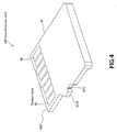
- FIG 4 is a schematic perspective view of the second memory card 200.
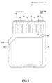
- FIG. 5 is a schematic plan view of the second memory card 200.
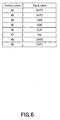
- FIG. 6 is a chart illustrating the correspondence between the contact pieces of second memory card 200 and signal names.
- the second memory card 200 includes a holder 30, a memory section (not shown) buried in the holder 30, a controller (not shown) also buried in the holder 30, a plurality of contact pieces 42 through 49 that are connected to the controller.
- the holder 30 has a thin plate-shaped profile and includes a printed circuit board that is covered by synthetic resin.
- the holder 30 has a thin and rectangular plate-shaped profile with a width smaller than the length thereof and a thickness smaller than the width thereof.
- the length, the width and the thickness of the holder 30 are respectively 15 mm, 11 mm and 1.0 mm.
- the holder 30 of the second memory card 200 has a length same as the holder 20 of the first memory card 100 but the thickness and the width of the holder 30 are smaller than those of the holder 20.
- the memory section, the controller and the plurality of contact pieces 42 through 49 are arranged on the printed circuit board.
- the memory section is formed by using a flash memory where data are rewritable.
- the controller controls data communications with external apparatus and data input/output operations relative to the memory section.
- the controller performs data communications with an external apparatus by way of an interface for the second memory card 200 when the second memory card 200 is mounted to the external apparatus.
- the contact pieces 42 through 49 are arranged in array on the surface along the transversal edges of the holder 30 at the longitudinal opposite ends of the holder 30. More specifically, the contact pieces 42 through 49 are aligned along the front edge 3002 of the surface.
- the contact pieces 42 through 49 are arranged at pitch P2, which is same as the pitch of arrangement of the contact pieces 2' through 10' of the first memory card 100.
- the plurality of contact pieces 42 through 49 include signal terminals for exchanging signals with the controller, a ground terminal for supplying the ground potential to the controller and the memory section and a power supply terminal for supplying power to the controller and the memory section.
- the contact piece 42 is a signal terminal for inputting/outputting data signal DAT2 and the contact piece 43 is a signal terminal for inputting/outputting data signal DAT3, while the contact piece 48 is a signal terminal for inputting/outputting data signal DAT0 and the contact piece 49 is a signal terminal for inputting/outputting data signal DAT1.
- the contact piece 44 is an input terminal for receiving command (CMD).
- the contact piece 45 is a power supply terminal where power source VDD is input.
- the contact piece 46 is a signal terminal for receiving clock signal CLK as input.
- Data signals DAT0 through DAT 3 are used for communications in synchronism with clock signal CLK.
- the contact piece 47 is a ground terminal connected to the ground level VSS.
- card tray 300 will be described below.
- FIG. 7A is a schematic plan view of the card tray 300
- FIG 7B is a schematic view of the card tray 300 as viewed in the direction of arrow B in FIG 7A.
- FIG 8C is a schematic view of the card tray 300 as viewed in the direction of arrow C in FIG 7B
- FIG 8D is a schematic view of the card tray 300 as viewed in the direction of arrow D in FIG 8C
- FIG 8E is a schematic view of the card tray 300 as viewed in the direction of arrow E in FIG 8C
- FIG 8F is a schematic view of the card tray 300 as viewed in the direction of arrow F in FIG. 8C.
- FIG 9A is a schematic perspective view of the card tray 300 and that of second memory card 200 to be mounted to the card tray 300
- FIG 9B is a schematic perspective view of the card tray 300 and that of second memory card 200 to be mounted to the card tray 300, FIG 9B being inverted views of FIG 9A.
- FIG 10A is a schematic perspective view of the card tray 300, showing the card tray 300 alone
- FIG 10B is an inverted schematic perspective view of the card tray 300, also showing the card tray 300 alone.
- the card tray 300 includes a main body 50 and a recessed mount section 52.
- the main body 50 has a rectangular plate-shaped profile and includes front edge and a rear edge that are arranged oppositely relative to each other as well as a left edge and a right edge that are arranged oppositely relative to each other. It has a width same as the holder 20 of the first memory card 100.
- the recessed mount section 52 is formed on one of the major surfaces of the main body 50 so as to receive the holder 30 of the second memory card 200.
- FIG 11A is a schematic view of the memory-card-mounted body 400
- FIG. 11B is an inverted schematic perspective view of the memory-card-mounted body 400.
- FIG 12A is a schematic perspective view of the first memory card 100
- FIG 12B is a schematic perspective view of the memory-card-mounted body 400.
- the memory-card-mounted body 400 is formed as the second memory card 200 is mounted to the recessed mount section 52.
- the recessed mount section 52 is defmed by a rear wall 5204, a left wall 5206 and a right wall 5208 that extend respectively along the rear edge, the left edge and the right edge of the main body 50 and also by the bottom wall 5202 that is surrounded by the rear wall 5204, the left wall 5206 and the right wall 5208.
- a rear wall 5204 a left wall 5206 and a right wall 5208 that extend respectively along the rear edge, the left edge and the right edge of the main body 50 and also by the bottom wall 5202 that is surrounded by the rear wall 5204, the left wall 5206 and the right wall 5208.
- the recessed mount section 52 is defmed by a rear wall 5204, a left wall 5206 and a right wall 5208 that extend respectively along the rear edge, the left edge and the right edge of the main body 50 and also by the bottom wall 5202 that is surrounded by the rear wall 5204, the left wall 5206 and the right wall 5208.
- it is open at the side of one of the major surfaces of the main body and
- the rear wall 5204 has an opening 5205 located on the bottom wall 5202 and extends transversally for receiving the second memory card 200 to be inserted therein from the front edge 3002 of the second memory card 200.
- the inner surface of the right wall 5208 that faces the recessed mount section 52 is provided with an engaging recess 5210 to be engaged with engaging projection 3010 of the second memory card 200 and an engaging projection 5212 to be engaged with engaging recess 3012 of the second memory card 200 as shown in FIG 5.
- the engaging section of the claims is formed by the engaging projection 3010 and the engaging recess 3012
- the engaging section of the claims is formed by the engaging recess 5210 and the engaging projection 5212.
- the inner surface of the left wall 5206 that faces the recessed mount section 52 is a flat surface.
- the thickness of the main body 50 and the depth of the recessed mount section 52 have such dimensions that the height from the other major surface of the main body 50 to the surface of the second memory card 200 is same as the thickness of the first memory card 100 when the second memory card 200 is mounted to the recessed mount section 52 with the surface of the second memory card 200 facing away from the recessed mount section 52.
- the memory-card-mounted body 400 and the first memory card 100 have the same thickness.
- the length of the main body 50 is same as that of the second memory card 200.
- the width of the main body 50 is larger than the width of the second memory card 200.
- the length of the recessed mount section 52 is smaller than the length of the second memory card 200 as the second memory card 200 is inserted into the opening 5210 from the front edge 3002 of the second memory card 200.
- the width of the recessed mount section 52 is substantially same as that of the second memory card 200.
- the second memory card 200 is mounted to the recessed mount section 52, the second memory card 200 is contained within the profile of the card tray 300 as viewed from above.
- FIG 13 is a schematic view of the memory-card-mounted body 400 illustrating the profiles of contact pieces 1 through 11 and 2' through 10' of first memory card 100 aligned with the memory-card-mounted body 400.
- FIG 14 is a chart illustrating the corresponding relationship between contact pieces 2' through 10' of first memory card 100 of FIG 13 and contact pieces 42 through 49 of second memory card 200.
- the contact pieces 3' through 10' of the first memory card 100 and the contact pieces 42 through 49 of the second memory card 200 have longitudinally overlapping parts and transversally overlapping parts as viewed from above.
- signals DAT2, DAT3, CMD, VDD, CLK, VSS, DAT0 and DAT1 assigned respectively to the contact pieces 42 through 49 of the second memory card 200 correspond respectively to the contact pieces 3' through 10' of the first memory card 100.
- the profile of the first memory card 100 and the profile of the card tray 300 agree with each other when the first memory card 100 is placed on the card tray 300 with the left and right edges thereof aligned with each other and viewed from above.
- a recess 5214 is formed on the outer surface of the right wall 5208 at a rearward position.
- a pair of recesses 5216 are formed on the outer surface of the left wall 5206 at longitudinal middle positions and separated from each other by a gap.
- the recess 5214 of the right wall 5208 and the two recesses 5216 of the left wall 5206 are aligned respectively with the recess 2010 and the two recesses 2012 of the first memory card 100 when the first memory card 100 is placed on the card tray 300 with the left and right edges thereof aligned with each other and viewed from above. More specifically, the recess 5214 and the recesses 5216 of the card tray 300 respectively and exactly agree with the recess 2010 and the recesses 2012 of the first memory card 100 in terms of both profile and position.
- front end of the outer surface of the left wall 5206 and the front end of the outer surface of the right wall 5208 are provided with respective curved surfaces 5218 so as to allow the second memory card 200 to be inserted into the card slot with ease.
- the second memory card 200 When the second memory card 200 is mounted to the card tray 300 to form the memory-card-mounted body 400, the second memory card 200 is inserted into the opening 5210 from the front edge 3002 thereof with the rear face of the second memory card 200 facing the recessed mount section 52 of the card tray 300 and the rear surface of the second memory card 200 is held in contact with the surface of the recessed mount section 52 of the card tray 300.
- the second memory card 200 When the second memory card 200 is taken out from the card tray 300, the second memory card 200 that is held in contact with the surface of the recessed mount section 52 of the card tray 300 is lifted at the rear edge thereof to disengage the engagement of the engaging projection 3010 and the engaging recess 5210 and also the engagement of the engaging recess 3012 and the engaging projection 5212. Then, the second memory card 200 is moved upward and frontward from the card tray 300 and pulled out through the opening 5210 from the front edge 3002 of the second memory card 200.
- the external apparatus includes a card slot for receiving a first memory card 100 or a memory-card-mounted body 400 and a control section for writing data in or reading data from the first memory card 100 or the memory-card-mounted body 400 mounted in the card slot.
- the card slot has terminals to be respectively electrically connected to the contact pieces 1 through 11 and the contact pieces 2' through 10' of the first memory card 100 when the first memory card 100 is mounted in it.
- the terminals that respectively correspond to the contact pieces 3' through 10' are electrically connected to the contact pieces 42 through 49 to make it possible to write data in and read data from the memory-card-mounted body 400, or the second memory card 200 to be more accurate.
- the terminals of the card slot are directly electrically connected respectively to the corresponding contact pieces 42 through 49 of the second memory card 200.
- the card tray 300 does not have to have first adaptor side contact pieces to be electrically connected to the contact pieces 42 through 49 of the second memory card 200, second adaptor side contact pieces to be electrically connected to the terminals of the card slot and conductor members for electrically connecting the first adaptor side contact pieces and the second adaptor side contact pieces so that it is possible to make the external dimensions of the card tray 300 agree with the external dimensions of downsized first memory card 100. Then, it is possible to mount the second memory card 200 in the card slot for receiving first memory card 100 by mounting the second memory card 200 to the card tray 300.
- the card slot is provided with a ground terminal (connected to the ground level of the external apparatus) to be connected to the ground (VSS) contact piece 54A and an INS tenninal to be connected to the INS signal contact piece 54B when the card tray 300 is inserted into the card slot.
- a ground terminal connected to the ground level of the external apparatus
- the ground (VSS) contact piece 54A and an INS tenninal to be connected to the INS signal contact piece 54B when the card tray 300 is inserted into the card slot.
- control section monitors the signal supplied to the INS terminal and detects if the signal level of the INS terminal is at the ground level or not, the control section can easily find out if the card tray 300 is inserted into the card slot or not.
- the main body 50 of the card tray 300 may be provided on the left wall 5206 or the right wall 5208 with an identification recess apart from the recesses 5214, 5216 that are already formed while the card slot may be provided with a detection switch for detecting the identification recess so that the control section may be able to find out if it is a first memory card 100 or a memory-card-mounted body 400 that is inserted into the card slot according to the operation of the detection switch.
- the card tray 300 may be provided with an identification recess to be used for the purpose of identifying the memory-card-mounted body 400 carrying a second memory card 200.
- control section of the external apparatus can find out with ease if the card tray 300 is inserted into the card slot or not by detecting and monitoring the operation of the detection switch.
- the main body 50 of the card tray 300 may alternatively be provided at a part thereof facing rearward with an anti-release mechanism for preventing the second memory card 200 from being freed from the recessed mount section 52 once it is mounted to and engaged with the recessed mount section 52.
- the anti-release mechanism will be projecting from the profile of the first memory card 100 when the first memory card 100 is placed on the card tray 300 with the left and right edges thereof aligned with each other and viewed from above.
- the anti-release mechanism will not obstruct at all the operation of mounting the memory-card-mounted body 400 in the card slot because it is located outside the card slot when the memory-card-mounted body 400 is mounted in the card slot.
- the second memory card 200 and the card tray 300 may be bonded to each other by means of a two-sided adhesive tape or like for the purpose of preventing the second memory card 200 from being released.
- the main body 50 of the card tray 300 may be provided at the front end of the left wall 5206 and at the front end of the right wall 5208 with a reinforcement wall that connects those front ends of the left wall 5206 and the right wall 5208.
- the reinforcement wall will be projecting from the profile of the first memory card 100 when the first memory card 100 is placed on the card tray 300 with the left and right edges thereof aligned with each other and viewed from above and the positions of the contact pieces 42 through 49 of the second memory card 200 are displaced rearward by the thickness of the reinforcement wall when the memory-card-mounted body 400 is mounted in the card slot.
- a card tray according to the embodiment of the present invention is applicable to a situation where the length of the holder 30 of the second memory card 200 is smaller than the length of the holder 20 of the first memory card 100 without any problem.
- the ratio of the projection area of the holder 30 of the second memory card 200 that is the product of multiplication of the length and the width of the holder 30 of the second memory card 200 to the projection area of the holder 20 of the first memory card 100 that is the product of multiplication of the length and the width of the holder 20 of the first memory card 100 is no less than 70% and not more than 95% of the projection area of the card tray 300.
- the second memory card 200 may be mounted longitudinally oppositely to the recessed mount section 52.
- the rear edge of the second memory card 200 comes to be aligned with the rear wall 5204 of the recessed mount section 52 of the card tray 300 while the front edge of the second memory card 200 comes to be aligned with the open part of the front edge of the recessed mount section 52 when the second memory card 200 is mounted to the recessed mount section 52 of the card tray 300.
- first memory card 100 is a memory card prepared according to specifications substantially same as those of Memory Sticks in terms of interface but having downsized external dimensions if compared with a Memory Stick and the second memory card 200 is a TransFlash in the above description of the embodiment, the format of the first memory card 100 and that of the second memory card 200 are not limited to those listed above.
- the present invention is by no means limited thereto so long as data can be written in and/or read from the memory sections.
Landscapes
- Engineering & Computer Science (AREA)
- Physics & Mathematics (AREA)
- General Physics & Mathematics (AREA)
- Theoretical Computer Science (AREA)
- Computer Hardware Design (AREA)
- Microelectronics & Electronic Packaging (AREA)
- Coupling Device And Connection With Printed Circuit (AREA)
- Credit Cards Or The Like (AREA)
Abstract
Description
- The present invention contains subject matter related to
Japanese Patent Application JP 2005-215965 filed in the Japanese Patent Office on July 26, 2005 - The present invention relates to a card tray to which a memory card is mounted.
- Memory cards including a writable flash memory are being marketed so as to be used for writing data in and reading data from the flash memory.
- Such a memory card is typically mounted in the card slot (connector) of an external apparatus such as personal computer or portable telephone set so as to be used for writing data in and reading data from the flash memory of the memory card.
- Known memory cards include Memory Sticks (Registered Trademark, available from Sony Corporation), Multi Media Cards (MMC: Registered Trademark, available from Infineon Technologies AG) and SD Cards (Registered Trademark, available from Matsushita Electric Industrial Co., Ltd., Toshiba Corporation and SanDisk, Inc.).
- The above listed known memory cards are manufactured according to different sets of product specifications that differ from each other in terms of external dimensions, outer profiles, interfaces to be used for data communications with external apparatus including standards defming the type and the number of signals for data communications and the sequence of data communications.
- Therefore, any single card slot for receiving a memory card is not able to receive memory cards of different types.
- For this reason, if there are first and second memory cards manufactured according to different sets of specifications, in case of mounting the second memory card in the card slot for the first memory card, a memory card adaptor for converting the set of specifications for the second card to the set of specifications for the first card is used (see Patent Document 1: Jpn. Pat. Appln. Laid-Open Publication No.
2004-265621 - That is, by mounting the second memory card to the memory card adaptor, the second memory card can be mounted in the card slot for the first memory card through the memory card adaptor.
- Now, such a memory card adaptor has to include first adaptor side contact pieces to be electrically connected to the signal input/output contact pieces of the second memory card, second adaptor side contact pieces to be electrically connected to the terminals of the card slot and conductors for electrically connecting the first adaptor side contact pieces and the second adaptor side contact pieces in order to electrically connect the signal input/output contact pieces of the second memory card and the terminals of the card slot.
- Thus, space for arranging these contact pieces and the conductors is necessary to the memory card adaptor.
- However, downsized memory cards of a plurality of different types having external dimensions smaller than those of existing memory cards have been proposed in recent years.
- Such downsized memory cards include TransFlash cards (Registered Trademark, available from SanDisk, Inc.) whose electric specifications are substantially same as those of SD cards.
- As a matter of course, memory card adaptors to be used for such downsized memory cards have reduced external dimensions.
- Then, it is difficult for memory card adaptors for receiving such downsized memory cards to secure space for arranging contact pieces and conductors to a great disadvantage for manufacturing such memory card adaptors.
- In view of the above-identified circumstances, it is desirable to provide a card tray to be mounted to a memory card that can make the memory card mountable in a card slot for memory cards conforming to standards different from those to which the memory card conforms even the memory card is a downsized one.
- According to an embodiment of the present invention, there is provided a card tray to be mounted to a second memory card that is mounted to a first memory card, the first memory card having a memory section buried in a rectangular plate-shaped holder having a length and a width dimensionally larger than the thickness thereof and a plurality of contact pieces arranged transversally in array on the surface of the holder, the second memory card having a memory section buried in a rectangular plate-shaped holder smaller than the holder of the first memory card and a plurality of contact pieces arranged transversally in array on the surface of the holder at the same pitch as that of the contact pieces of the first memory card, the card tray including: a thin plate-shaped main body; and an open and recessed mount section formed on one of the major surfaces of the main body to which the holder of the second memory card is mounted; a memory-card-mounted body being formed by mounting the second memory card to the recessed mount section with the surface directed opposite to the recessed mount section, the thickness and the width of the memory-card-mounted body being same and identical with the thickness and the width of the first memory card.
- Thus, according to the embodiment of the present invention, as the memory-card-mounted body is inserted into a card slot for receiving a first memory card, the terminals of the card slot are electrically directly connected to the corresponding respective contact pieces of the second memory card.
- Therefore, unlike card adaptors used in the past, the card tray does not have to have any adaptor side contact pieces and conductor members and hence it is possible to make the external dimensions of the card tray agree with those of the downsized first memory card so that the second memory card can be mounted in the card slot for receiving the first memory card by mounting it to a card tray and forming a memory-card-mounted body.
-
- FIG 1 is a schematic perspective view of a
first memory card 100; - FIG. 2A is a schematic plan view of the
first memory card 100, and FIG 2B is a schematic cross sectional view of thefirst memory card 100; - FIGS. 3A and 3B are charts illustrating the correspondence between the contact pieces of the
first memory card 100 and signal names; - FIG 4 is a schematic perspective view of a
second memory card 200; - FIG 5 is a schematic plan view of the
second memory card 200; - FIG 6 is a chart illustrating the correspondence between the contact pieces of the
second memory card 200 and signal names; - FIG 7A is a schematic plan view of a
card tray 300, and FIG 7B is a schematic view of thecard tray 300 as viewed in the direction of arrow B in FIG 7A; - FIG 8C is a schematic view of the
card tray 300 as viewed in the direction of arrow C in FIG 7B, FIG 8D is a schematic view of thecard tray 300 as viewed in the direction of arrow D in FIG 8C, while FIG. 8E is a schematic view of thecard tray 300 as viewed in the direction of arrow E in FIG 8C and FIG 8F is a schematic view of thecard tray 300 as viewed in the direction of arrow F in FIG. 8C; - FIG 9A is a schematic perspective view of the
card tray 300 and that of thesecond memory card 200 to be mounted to thecard tray 300, and FIG. 9B is a schematic perspective view of thecard tray 300 and that of thesecond memory card 200 to be mounted to thecard tray 300, FIG 9B being inverted views of FIG. 9A; - FIG 10A is a schematic perspective view of the
card tray 300, showing thecard tray 300 alone, and FIG 10B is an inverted schematic perspective view of thecard tray 300, also showing thecard tray 300 alone; - FIG 11A is a schematic view of a memory-card-mounted
body 400, and FIG 11B is an inverted schematic perspective view of the memory-card-mountedbody 400; - FIG 12A is a schematic perspective view of the
first memory card 100, and FIG 12B is a schematic perspective view of the memory-card-mountedbody 400; - FIG 13 is a schematic view of the memory-card-mounted
body 400 illustrating the profiles ofcontact pieces 1 through 11 and 2' through 10' of thefirst memory card 100 aligned with the memory-card-mountedbody 400; - FIG 14 is a chart illustrating the corresponding relationship between contact pieces 2' through 10' of the
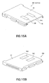
first memory card 100 of FIG 13 andcontact pieces 42 through 49 of thesecond memory card 200; - FIG 15A and FIG. 15B are schematic perspective views of modified
card tray 300; and - FIG 16A and FIG 16B are schematic perspective views of modified
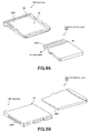
card tray 300 illustrating the direction in which thesecond memory card 200 is mounted to the modified card tray. - Now, the first embodiment of the present invention will be described in detail by referring to the accompanying drawings.
- FIG 1 is a schematic perspective view of a
first memory card 100. - FIG 2A is a schematic plan view of the
first memory card 100, and FIG 2B is a schematic cross sectional view of thefirst memory card 100. - FIG. 3A is a chart illustrating the correspondence between the contact pieces of the
first memory card 100 and signal names. - In the following description, the side of each of the
first memory card 100 andsecond memory card 200 by which the card is inserted into a card slot is referred to as front edge whereas the side of each offirst memory card 100 andsecond memory card 200 by which the card is taken out from the card slot is referred to as rear edge. - The side of each of the
first memory card 100 andsecond memory card 200 andcard tray 300 that is found at the right side as viewed from the rear edge is referred to as right edge, whereas the side of each of those that is found at the left side as viewed from the rear edge is referred to as left edge. - Firstly, two memory cards, or first memory card 100 (see FIG. 1) and second memory card 200 (see FIG. 4), that are prepared according to respective sets of specifications will be described.
- For the purpose of this embodiment, the
first memory card 100 is a memory card prepared according to specifications substantially same as those of Memory Sticks (Registered Trademark, available from Sony Corporation) in terms of interface but having downsized external dimensions if compared with a Memory Stick. - For the purpose of this embodiment, the
second memory card 200 is a TransFlash (Registered Trademark, available from SanDisk, Inc.) prepared according to specifications substantially same as those of SD cards (Registered Trademark, available from Matsushita Electric Industrial Co., Ltd., Toshiba Corporation and SanDisk, Inc.) in terms of interface but having downsized external dimensions if compared with a TransFlash. - The
second memory card 200 has a thickness and a width smaller than those of thefirst memory card 100 but a length same as that of thefirst memory card 100. - As shown in FIGS. 2A and 2B, the
first memory card 100 includes aholder 20, amemory section 22 buried in theholder 20, acontroller 24 also buried in theholder 20, a plurality ofcontact pieces 1 through 11 and 2' through 10' that are connected to thecontroller 24. - The
holder 20 has a thin plate-shaped profile and includes a printedcircuit board 21 that is covered by synthetic resin. - As pointed out above, the
holder 20 has a thin and rectangular plate-shaped profile with a width smaller than the length thereof and a thickness smaller than the width thereof. In this embodiment, the length, the width and the thickness of theholder 20 are respectively 15 mm, 12 mm and 1.2 mm. - The printed
circuit board 21 is covered by insulating synthetic resin at the two oppositely disposed major surfaces thereof. The synthetic resin may typically be PC (polycarbonate) or liquid crystal polymer. - While the
memory section 22 and thecontroller 24 are illustrated separately in FIGS. 2A and 2B for the purpose of easy understanding, they may be arranged to show any of known sophisticated structures such as a multilayer structure. - The
memory section 22, thecontroller 24 and the plurality ofcontact pieces 1 through 11 and 2' through 10' are arranged on the printedcircuit board 21. - The
memory section 22 is formed by using a flash memory where data are rewritable. - The
controller 24 controls data communications with external apparatus and data input/output operations relative to thememory section 22. - The
controller 24 performs data communications with an external apparatus by way of a predetermined interface for thefirst memory card 100 when thefirst memory card 100 is mounted to the external apparatus. A predetermined interface as used herein refers to one that conforms to a given standard for data communications in terms of types and numbers of signals to be used for data communications and sequence of data communications. - The
memory section 22, thecontroller 24 and thecontact pieces 1 through 11 and 2' through 10' are arranged on the surface of theholder 20 opposite to the side where the printedcircuit board 21 is arranged. - As shown in FIG 2A, the
contact pieces 1 through 11 and 2' through 10' are arranged in array on the surface along the transversal edges of theholder 20 at the longitudinal opposite ends of theholder 20. More specifically, thecontact pieces 1 through 11 are aligned along thefront edge 2002 of the surface, whereas the contact pieces 2' through 10' are aligned along therear edge 2004 of the surface. - The
contact pieces 1 through 11 are arranged at a same pitch P1. - The contact pieces 2' through 10' are arranged at a same pitch P2, which is larger than the pitch P1.
- While the
contact pieces 1 through 11 and 2' through 10' are connected to thecontroller 24 by way of an electro-conductive pattern formed on the printedcircuit board 21, the electro-conductive pattern is omitted from FIGS. 2A and 2B for the purpose of simplicity. - The plurality of
contact pieces 1 through 11 and 2' through 10' include signal terminals for exchanging signals with thecontroller 24, a ground terminal for supplying the ground potential to thecontroller 24 and thememory section 22 and a power supply terminal for supplying power to thecontroller 24 and thememory section 22. - More specifically, as shown in FIG. 3A, the
contact piece 1 is a signal terminal where bus state signal BS for indicating a gap separating the data to be transmitted/received by way of data signals DATA0 through DATA3 is input. - The
contact piece 2 is a signal terminal for inputting/outputting data signal DATA1 and thecontact piece 3 is a signal terminal for inputting/outputting data signal DATA0, whereas thecontact piece 4 is a signal terminal for inputting/outputting data signal DATA2 and thecontact piece 6 is a signal terminal for inputting/outputting data signal DATA3. - The contact piece 3' is a signal terminal for inputting/outputting data signal DATA5 and the contact piece 4' is a signal terminal for inputting/outputting data signal DATA4, whereas the contact piece 5' is a signal terminal for inputting/outputting data signal DATA6 and the contact piece 6' is a signal terminal for inputting/outputting data signal DATA7.
- Note that the contact pieces 2', 7' and 10' are not used in this embodiment.
- The
contact piece 5 is an insertion/withdrawal detection contact piece. It is a signal terminal for supplying an INS signal to be used by the external apparatus in order to detect insertion/withdrawal of a memory card. In this embodiment, an INS signal showing the GND level indicates that a memory card is mounted. - The
contact piece 7 is a signal terminal for receiving clock signal SCLK as input. Above-described bus state signal BS and data signals DATA0 through DATA7 are used for communications in synchronism with clock signal SCLK. - The
contact piece 8 is a power supply terminal where source voltage Vcc is input. - The
contact piece 9 is a ground terminal connected to the ground level VSS. - The
contact pieces controller 24 has a feature of being able to perform data communications by way of a plurality of different interfaces, it can select the interface to be used for data communication by receiving interface switching signals D1, D2 from the external apparatus. Interface switching may be bit width switching (e.g., from 4 bits width to 8 bits width or vice versa) to be used for data communications. However, interface switching will not be described any further because it is not directly related to the gist of the present invention. - Note, however, that the combinations of the contact pieces of the
first memory card 100 and signals are not limited to those listed in FIG. 3A. For example, DATA6, DATA7 may be assigned respectively to the contact pieces 9', 10' instead of being assigned to the contact pieces 5', 6' as shown in FIG 3B. - Now, the
second memory card 200 will be described below. - FIG 4 is a schematic perspective view of the
second memory card 200. - FIG. 5 is a schematic plan view of the
second memory card 200. - FIG. 6 is a chart illustrating the correspondence between the contact pieces of
second memory card 200 and signal names. - As shown in FIGS. 4 and 5, the
second memory card 200 includes aholder 30, a memory section (not shown) buried in theholder 30, a controller (not shown) also buried in theholder 30, a plurality ofcontact pieces 42 through 49 that are connected to the controller. - Like the
first memory card 100, theholder 30 has a thin plate-shaped profile and includes a printed circuit board that is covered by synthetic resin. - As pointed out above, the
holder 30 has a thin and rectangular plate-shaped profile with a width smaller than the length thereof and a thickness smaller than the width thereof. - In this embodiment, the length, the width and the thickness of the
holder 30 are respectively 15 mm, 11 mm and 1.0 mm. Thus, theholder 30 of thesecond memory card 200 has a length same as theholder 20 of thefirst memory card 100 but the thickness and the width of theholder 30 are smaller than those of theholder 20. - The memory section, the controller and the plurality of
contact pieces 42 through 49 are arranged on the printed circuit board. - The memory section is formed by using a flash memory where data are rewritable.
- The controller controls data communications with external apparatus and data input/output operations relative to the memory section.
- The controller performs data communications with an external apparatus by way of an interface for the
second memory card 200 when thesecond memory card 200 is mounted to the external apparatus. - As shown in FIG. 5, the
contact pieces 42 through 49 are arranged in array on the surface along the transversal edges of theholder 30 at the longitudinal opposite ends of theholder 30. More specifically, thecontact pieces 42 through 49 are aligned along thefront edge 3002 of the surface. - The
contact pieces 42 through 49 are arranged at pitch P2, which is same as the pitch of arrangement of the contact pieces 2' through 10' of thefirst memory card 100. - The plurality of
contact pieces 42 through 49 include signal terminals for exchanging signals with the controller, a ground terminal for supplying the ground potential to the controller and the memory section and a power supply terminal for supplying power to the controller and the memory section. - More specifically, as shown in FIG 6, the
contact piece 42 is a signal terminal for inputting/outputting data signal DAT2 and thecontact piece 43 is a signal terminal for inputting/outputting data signal DAT3, while thecontact piece 48 is a signal terminal for inputting/outputting data signal DAT0 and thecontact piece 49 is a signal terminal for inputting/outputting data signal DAT1. - The
contact piece 44 is an input terminal for receiving command (CMD). - The
contact piece 45 is a power supply terminal where power source VDD is input. - The
contact piece 46 is a signal terminal for receiving clock signal CLK as input. Data signals DAT0 throughDAT 3 are used for communications in synchronism with clock signal CLK. - The
contact piece 47 is a ground terminal connected to the ground level VSS. - Now, the
card tray 300 will be described below. - FIG. 7A is a schematic plan view of the
card tray 300, and FIG 7B is a schematic view of thecard tray 300 as viewed in the direction of arrow B in FIG 7A. - FIG 8C is a schematic view of the
card tray 300 as viewed in the direction of arrow C in FIG 7B, FIG 8D is a schematic view of thecard tray 300 as viewed in the direction of arrow D in FIG 8C, while FIG 8E is a schematic view of thecard tray 300 as viewed in the direction of arrow E in FIG 8C and FIG 8F is a schematic view of thecard tray 300 as viewed in the direction of arrow F in FIG. 8C. - FIG 9A is a schematic perspective view of the
card tray 300 and that ofsecond memory card 200 to be mounted to thecard tray 300, and FIG 9B is a schematic perspective view of thecard tray 300 and that ofsecond memory card 200 to be mounted to thecard tray 300, FIG 9B being inverted views of FIG 9A. - FIG 10A is a schematic perspective view of the
card tray 300, showing thecard tray 300 alone, and FIG 10B is an inverted schematic perspective view of thecard tray 300, also showing thecard tray 300 alone. - As shown in FIGS. 7A through 10B, the
card tray 300 includes amain body 50 and a recessedmount section 52. - The
main body 50 has a rectangular plate-shaped profile and includes front edge and a rear edge that are arranged oppositely relative to each other as well as a left edge and a right edge that are arranged oppositely relative to each other. It has a width same as theholder 20 of thefirst memory card 100. - The recessed
mount section 52 is formed on one of the major surfaces of themain body 50 so as to receive theholder 30 of thesecond memory card 200. - FIG 11A is a schematic view of the memory-card-mounted
body 400, and FIG. 11B is an inverted schematic perspective view of the memory-card-mountedbody 400. - FIG 12A is a schematic perspective view of the
first memory card 100, and FIG 12B is a schematic perspective view of the memory-card-mountedbody 400. - As shown in FIGS. 11A, 11B and 12B, the memory-card-mounted
body 400 is formed as thesecond memory card 200 is mounted to the recessedmount section 52. - As shown in FIGS. 7A through 8F, the recessed
mount section 52 is defmed by arear wall 5204, aleft wall 5206 and aright wall 5208 that extend respectively along the rear edge, the left edge and the right edge of themain body 50 and also by thebottom wall 5202 that is surrounded by therear wall 5204, theleft wall 5206 and theright wall 5208. Thus, it is open at the side of one of the major surfaces of the main body and also along the front edge. - The
rear wall 5204 has anopening 5205 located on thebottom wall 5202 and extends transversally for receiving thesecond memory card 200 to be inserted therein from thefront edge 3002 of thesecond memory card 200. - As shown in FIGS. 7A through 8F, the inner surface of the
right wall 5208 that faces the recessedmount section 52 is provided with anengaging recess 5210 to be engaged withengaging projection 3010 of thesecond memory card 200 and an engagingprojection 5212 to be engaged withengaging recess 3012 of thesecond memory card 200 as shown in FIG 5. In this embodiment, the engaging section of the claims is formed by the engagingprojection 3010 and theengaging recess 3012, and the engaging section of the claims is formed by the engagingrecess 5210 and the engagingprojection 5212. - The inner surface of the
left wall 5206 that faces the recessedmount section 52 is a flat surface. - As shown in FIGS. 7A through 9B, the thickness of the
main body 50 and the depth of the recessedmount section 52 have such dimensions that the height from the other major surface of themain body 50 to the surface of thesecond memory card 200 is same as the thickness of thefirst memory card 100 when thesecond memory card 200 is mounted to the recessedmount section 52 with the surface of thesecond memory card 200 facing away from the recessedmount section 52. Differently stated, the memory-card-mountedbody 400 and thefirst memory card 100 have the same thickness. - The length of the
main body 50 is same as that of thesecond memory card 200. - The width of the
main body 50 is larger than the width of thesecond memory card 200. - The length of the recessed
mount section 52 is smaller than the length of thesecond memory card 200 as thesecond memory card 200 is inserted into theopening 5210 from thefront edge 3002 of thesecond memory card 200. - The width of the recessed
mount section 52 is substantially same as that of thesecond memory card 200. - Thus, as the
second memory card 200 is mounted to the recessedmount section 52, thesecond memory card 200 is contained within the profile of thecard tray 300 as viewed from above. - FIG 13 is a schematic view of the memory-card-mounted
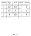
body 400 illustrating the profiles ofcontact pieces 1 through 11 and 2' through 10' offirst memory card 100 aligned with the memory-card-mountedbody 400. - FIG 14 is a chart illustrating the corresponding relationship between contact pieces 2' through 10' of
first memory card 100 of FIG 13 andcontact pieces 42 through 49 ofsecond memory card 200. - When the
first memory card 100 is placed on the memory-card-mountedbody 400 with the left and right edges thereof aligned with each other, the contact pieces 3' through 10' of thefirst memory card 100 and thecontact pieces 42 through 49 of thesecond memory card 200 have longitudinally overlapping parts and transversally overlapping parts as viewed from above. - In other words, as shown in FIG. 14, signals DAT2, DAT3, CMD, VDD, CLK, VSS, DAT0 and DAT1 assigned respectively to the
contact pieces 42 through 49 of thesecond memory card 200 correspond respectively to the contact pieces 3' through 10' of thefirst memory card 100. - In this embodiment, the profile of the
first memory card 100 and the profile of thecard tray 300 agree with each other when thefirst memory card 100 is placed on thecard tray 300 with the left and right edges thereof aligned with each other and viewed from above. - More specifically, a
recess 5214 is formed on the outer surface of theright wall 5208 at a rearward position. - A pair of
recesses 5216 are formed on the outer surface of theleft wall 5206 at longitudinal middle positions and separated from each other by a gap. - The
recess 5214 of theright wall 5208 and the tworecesses 5216 of theleft wall 5206 are aligned respectively with therecess 2010 and the tworecesses 2012 of thefirst memory card 100 when thefirst memory card 100 is placed on thecard tray 300 with the left and right edges thereof aligned with each other and viewed from above. More specifically, therecess 5214 and therecesses 5216 of thecard tray 300 respectively and exactly agree with therecess 2010 and therecesses 2012 of thefirst memory card 100 in terms of both profile and position. - Note that the front end of the outer surface of the
left wall 5206 and the front end of the outer surface of theright wall 5208 are provided with respectivecurved surfaces 5218 so as to allow thesecond memory card 200 to be inserted into the card slot with ease. - Now, how to use the
card tray 300 will be described below. - When the
second memory card 200 is mounted to thecard tray 300 to form the memory-card-mountedbody 400, thesecond memory card 200 is inserted into theopening 5210 from thefront edge 3002 thereof with the rear face of thesecond memory card 200 facing the recessedmount section 52 of thecard tray 300 and the rear surface of thesecond memory card 200 is held in contact with the surface of the recessedmount section 52 of thecard tray 300. - Under this condition, the engaging
projection 3010 and theengaging recess 5210 are engaged with each other while the engagingrecess 3012 and the engagingprojection 5212 are engaged with each other. - When the
second memory card 200 is taken out from thecard tray 300, thesecond memory card 200 that is held in contact with the surface of the recessedmount section 52 of thecard tray 300 is lifted at the rear edge thereof to disengage the engagement of the engagingprojection 3010 and theengaging recess 5210 and also the engagement of theengaging recess 3012 and the engagingprojection 5212. Then, thesecond memory card 200 is moved upward and frontward from thecard tray 300 and pulled out through theopening 5210 from thefront edge 3002 of thesecond memory card 200. - Now, an external apparatus to which a
first memory card 100 or a memory-card-mountedbody 400 is to be mounted will be described below. - The external apparatus includes a card slot for receiving a
first memory card 100 or a memory-card-mountedbody 400 and a control section for writing data in or reading data from thefirst memory card 100 or the memory-card-mountedbody 400 mounted in the card slot. - The card slot has terminals to be respectively electrically connected to the
contact pieces 1 through 11 and the contact pieces 2' through 10' of thefirst memory card 100 when thefirst memory card 100 is mounted in it. - Thus, as the memory-card-mounted
body 400 is mounted in the card slot, the terminals that respectively correspond to the contact pieces 3' through 10' are electrically connected to thecontact pieces 42 through 49 to make it possible to write data in and read data from the memory-card-mountedbody 400, or thesecond memory card 200 to be more accurate. - With this embodiment, as the memory-card-mounted
body 400 is inserted into the card slot adapted to receive afirst memory card 100, the terminals of the card slot are directly electrically connected respectively to thecorresponding contact pieces 42 through 49 of thesecond memory card 200. - Therefore, unlike card adaptors of above discussed type used in the past, the
card tray 300 does not have to have first adaptor side contact pieces to be electrically connected to thecontact pieces 42 through 49 of thesecond memory card 200, second adaptor side contact pieces to be electrically connected to the terminals of the card slot and conductor members for electrically connecting the first adaptor side contact pieces and the second adaptor side contact pieces so that it is possible to make the external dimensions of thecard tray 300 agree with the external dimensions of downsizedfirst memory card 100. Then, it is possible to mount thesecond memory card 200 in the card slot for receivingfirst memory card 100 by mounting thesecond memory card 200 to thecard tray 300. - For the control section of an external apparatus to recognize
first memory card 100 orsecond memory card 200 that is mounted in the card slot, it is sufficient to provide themain body 50 of thecard tray 300 with a ground (VSS)contact piece 54A and an INSsignal contact piece 54B that are electrically connected to each other on the rear surface thereof. - Then, the card slot is provided with a ground terminal (connected to the ground level of the external apparatus) to be connected to the ground (VSS)
contact piece 54A and an INS tenninal to be connected to the INSsignal contact piece 54B when thecard tray 300 is inserted into the card slot. - As the control section monitors the signal supplied to the INS terminal and detects if the signal level of the INS terminal is at the ground level or not, the control section can easily find out if the
card tray 300 is inserted into the card slot or not. - For the control section of an external apparatus to recognize
first memory card 100 orsecond memory card 200 that is mounted in the card slot, alternatively themain body 50 of thecard tray 300 may be provided on theleft wall 5206 or theright wall 5208 with an identification recess apart from therecesses first memory card 100 or a memory-card-mountedbody 400 that is inserted into the card slot according to the operation of the detection switch. In short, thecard tray 300 may be provided with an identification recess to be used for the purpose of identifying the memory-card-mountedbody 400 carrying asecond memory card 200. - With such an alternative arrangement, the control section of the external apparatus can find out with ease if the
card tray 300 is inserted into the card slot or not by detecting and monitoring the operation of the detection switch. - Note that, while the profile of the
first memory card 100 and the profile of thecard tray 300 agree with each other when thefirst memory card 100 is placed on thecard tray 300 with the left and right edges thereof aligned with each other and viewed from above in the above description of the embodiment, themain body 50 of thecard tray 300 may alternatively be provided at a part thereof facing rearward with an anti-release mechanism for preventing thesecond memory card 200 from being freed from the recessedmount section 52 once it is mounted to and engaged with the recessedmount section 52. - With such an alternative arrangement, the anti-release mechanism will be projecting from the profile of the
first memory card 100 when thefirst memory card 100 is placed on thecard tray 300 with the left and right edges thereof aligned with each other and viewed from above. However, the anti-release mechanism will not obstruct at all the operation of mounting the memory-card-mountedbody 400 in the card slot because it is located outside the card slot when the memory-card-mountedbody 400 is mounted in the card slot. - Still alternatively, the
second memory card 200 and thecard tray 300 may be bonded to each other by means of a two-sided adhesive tape or like for the purpose of preventing thesecond memory card 200 from being released. - While the profile of the
first memory card 100 and the profile of thecard tray 300 agree with each other when thefirst memory card 100 is placed on thecard tray 300 with the left and right edges thereof aligned with each other and viewed from above in the above description of the embodiment, themain body 50 of thecard tray 300 may be provided at the front end of theleft wall 5206 and at the front end of theright wall 5208 with a reinforcement wall that connects those front ends of theleft wall 5206 and theright wall 5208. - With such an alternative arrangement, the reinforcement wall will be projecting from the profile of the
first memory card 100 when thefirst memory card 100 is placed on thecard tray 300 with the left and right edges thereof aligned with each other and viewed from above and the positions of thecontact pieces 42 through 49 of thesecond memory card 200 are displaced rearward by the thickness of the reinforcement wall when the memory-card-mountedbody 400 is mounted in the card slot. However, it is possible to secure the electric connections between thecontact pieces 42 through 49 of thesecond memory card 200 and the corresponding respective terminals of the card slot because each of thecontact pieces 42 through 49 of thesecond memory card 200 covers a certain longitudinal distance. - While the
holder 30 of thesecond memory card 200 and theholder 20 of thefirst memory card 100 have a same length but the thickness and the width of theholder 30 are smaller than those of theholder 20 in the above description of the embodiment, a card tray according to the embodiment of the present invention is applicable to a situation where the length of theholder 30 of thesecond memory card 200 is smaller than the length of theholder 20 of thefirst memory card 100 without any problem. - In this embodiment, the ratio of the projection area of the
holder 30 of thesecond memory card 200 that is the product of multiplication of the length and the width of theholder 30 of thesecond memory card 200 to the projection area of theholder 20 of thefirst memory card 100 that is the product of multiplication of the length and the width of theholder 20 of thefirst memory card 100 is no less than 70% and not more than 95% of the projection area of thecard tray 300. - While the
rear wall 5204 of the recessedmount section 52 of thecard tray 300 comes to be aligned with the front edge of thesecond memory card 200 while the open part of the front edge of the recessedmount section 52 comes to be aligned with the rear edge of thesecond memory card 200 when thesecond memory card 200 is mounted to the recessedmount section 52 of thecard tray 300 in the above description of the embodiment, thesecond memory card 200 may be mounted longitudinally oppositely to the recessedmount section 52. - With such an arrangement as shown in FIGS. 16A and 16B, the rear edge of the
second memory card 200 comes to be aligned with therear wall 5204 of the recessedmount section 52 of thecard tray 300 while the front edge of thesecond memory card 200 comes to be aligned with the open part of the front edge of the recessedmount section 52 when thesecond memory card 200 is mounted to the recessedmount section 52 of thecard tray 300. - The advantages of the above-described embodiment remain unchanged with such an alternative arrangement.
- While the
first memory card 100 is a memory card prepared according to specifications substantially same as those of Memory Sticks in terms of interface but having downsized external dimensions if compared with a Memory Stick and thesecond memory card 200 is a TransFlash in the above description of the embodiment, the format of thefirst memory card 100 and that of thesecond memory card 200 are not limited to those listed above. - While the memory sections of the first and
second memory cards - It should be understood by those skilled in the art that various modifications, combinations, sub-combinations and alterations may occur depending on design requirements and other factors insofar as they are within the scope of the appended claims or the equivalents thereof.
Claims (9)
- A card tray to be mounted to a second memory card that is mounted to a first memory card, the first memory card having a memory section buried in a rectangular plate-shaped holder having a length and a width dimensionally larger than the thickness thereof and a plurality of contact pieces arranged transversally in array on the surface of the holder, the second memory card having a memory section buried in a rectangular plate-shaped holder smaller than the holder of the first memory card and a plurality of contact pieces arranged transversally in array on the surface of the holder at the same pitch as that of the contact pieces of the first memory card, the card tray comprising:a thin plate-shaped main body; andan open and recessed mount section formed on one of the major surfaces of the main body to which the holder of the second memory card is mounted;a memory-card-mounted body being formed by mounting the second memory card to the recessed mount section with the surface directed opposite to the recessed mount section,the thickness and the width of the memory-card-mounted body being same and identical with the thickness and the width of the first memory card.
- The card tray according to claim 1, wherein the first memory card and the memory-card-mounted body respectively have front edges, rear edges, left edges and right edges that are located opposite to each other and, when the first memory card is placed on the memory-card-mounted body with the front and rear edges thereof aligned with each other and the left and right edges thereof aligned with each other, the plurality of contact pieces of the first memory card and the plurality of contact pieces of the second memory card have longitudinally overlapping parts and transversally overlapping parts as viewed from above.
- The card tray according to claim 1, wherein the main body of the card tray has a front edge and a rear edge arranged oppositely relative to each other and a left edge and a right edge arranged oppositely relative to each other to show a rectangular plate-shaped profile and the recessed mount section is defined by a rear wall, a left wall and a right wall extended respectively along the rear edge, the left edge and the right edge of the main body and also by the bottom wall surrounded by the rear wall, the left wall and the right wall, the recessed mount section being open along the front edge.
- The card tray according to claim 1, wherein the main body of the card tray has a front edge and a rear edge arranged oppositely relative to each other and a left edge and a right edge arranged oppositely relative to each other to show a rectangular plate-shaped profile and the recessed mount section is defined by a rear wall, a left wall and a right wall extending respectively along the rear edge, the left edge and the right edge of the main body and also by the bottom wall surrounded by the rear wall, the left wall and the right wall, the recessed mount section being open along the front edge, an transversally extending opening being formed through the rear wall on the bottom wall, while the holder of the second memory card has a front edge and a rear edge arranged oppositely relative to each other and a left edge and a right edge arranged oppositely relative to each other and the memory-card-mounted body is inserted into the opening at the front edge of the holder of the second memory card.
- The card tray according to claim 1, wherein the main body of the card tray has a front edge and a rear edge arranged oppositely relative to each other and a left edge and a right edge arranged oppositely relative to each other to show a rectangular plate-shaped profile and the recessed mount section is defined by a rear wall, a left wall and a right wall extending respectively along the rear edge, the left edge and the right edge of the main body and also by the bottom wall surrounded by the rear wall, the left wall and the right wall, the recessed mount section being open along the front edge, an transversally extending opening being formed through the rear wall on the bottom wall, an engaging section being formed at a position facing the bottom wall on either the left wall or the right wall, while the holder of the second memory card has a front edge and a rear edge arranged oppositely relative to each other and a left edge and a right edge arranged oppositely relative to each other, an engaging section being formed either at the left edge or the right edge so as to be able to be engaged with the engaging section, and the memory-card-mounted body is inserted into the opening at the front edge of the holder of the second memory card in such a way that the engaging section at the left wall is engaged with the engaging section at the left edge or the right edge.
- The card tray according to claim 1, wherein the main body of the card tray has a front edge and a rear edge arranged oppositely relative to each other and a left edge and a right edge arranged oppositely relative to each other to show a rectangular plate-shaped profile and the recessed mount section is defmed by a rear wall, a left wall and a right wall extending respectively along the rear edge, the left edge and the right edge of the main body and also by the bottom wall surrounded by the rear wall, the left wall and the right wall, the recessed mount section being open along the front edge, an identification recess being formed at least at the left wall or the right wall for identifying the memory-card-mounted body.
- The card tray according to claim 1, wherein the card tray is formed in such a way that the profile of the first memory card and that of the card tray agree with each other when the first memory card is placed on the card tray and viewed from above.
- The card tray according to claim 1, wherein the holder of the second memory card is so formed as to show a length smaller than the length of the holder of the first memory card.
- The card tray according to claim 1, wherein the ratio of the projection area of the holder of the second memory card that is the product of multiplication of the length and the width of the holder of the second memory card to the projection area of the holder of the first memory card that is the product of multiplication of the length and the width of the holder of the first memory card is no less than 70% and not more than 95%.
Applications Claiming Priority (1)
| Application Number | Priority Date | Filing Date | Title |
|---|---|---|---|
| JP2005215965A JP2007034612A (en) | 2005-07-26 | 2005-07-26 | Card tray |
Publications (2)
| Publication Number | Publication Date |
|---|---|
| EP1748380A2 true EP1748380A2 (en) | 2007-01-31 |
| EP1748380A3 EP1748380A3 (en) | 2010-11-10 |
Family
ID=37402538
Family Applications (1)
| Application Number | Title | Priority Date | Filing Date |
|---|---|---|---|
| EP06014151A Withdrawn EP1748380A3 (en) | 2005-07-26 | 2006-07-07 | Memory card adaptor |
Country Status (6)
| Country | Link |
|---|---|
| US (1) | US7458519B2 (en) |
| EP (1) | EP1748380A3 (en) |
| JP (1) | JP2007034612A (en) |
| KR (1) | KR20070014033A (en) |
| CN (1) | CN1905282B (en) |
| TW (1) | TW200731621A (en) |
Cited By (1)
| Publication number | Priority date | Publication date | Assignee | Title |
|---|---|---|---|---|
| FR2989199A1 (en) * | 2012-04-04 | 2013-10-11 | Oberthur Technologies | Format adapter for chip card e.g. bank card, complying small format in full screen, has flat connector including set of contacts, and junction unit that is allowed to connect set of contacts of flat connector with contact of contact surface |
Families Citing this family (28)
| Publication number | Priority date | Publication date | Assignee | Title |
|---|---|---|---|---|
| US20070218768A1 (en) * | 2006-03-20 | 2007-09-20 | Yun-Hsiu Lee | Transflash-to-SD adaptive card structure |
| TW200823626A (en) * | 2006-11-28 | 2008-06-01 | qin-dong Liu | Improved memory card structure |
| US7865210B2 (en) | 2007-01-05 | 2011-01-04 | Apple Inc. | Ejectable component assemblies in electronic devices |
| USD591752S1 (en) * | 2007-12-06 | 2009-05-05 | Sony Corporation | Memory card |
| USD638431S1 (en) * | 2009-10-20 | 2011-05-24 | Sandisk Corporation | MicroSD memory card with a semi-transparent color surface |
| US8690283B2 (en) | 2009-10-20 | 2014-04-08 | Sandisk Il Ltd. | Method and system for printing graphical content onto a plurality of memory devices and for providing a visually distinguishable memory device |
| USD639812S1 (en) * | 2010-05-17 | 2011-06-14 | Panasonic Corporation | Memory card |
| USD643040S1 (en) * | 2010-10-26 | 2011-08-09 | Hon Hai Precision Ind. Co., Ltd. | Electrical card |
| US8649820B2 (en) | 2011-11-07 | 2014-02-11 | Blackberry Limited | Universal integrated circuit card apparatus and related methods |
| US8936199B2 (en) | 2012-04-13 | 2015-01-20 | Blackberry Limited | UICC apparatus and related methods |
| USD703208S1 (en) | 2012-04-13 | 2014-04-22 | Blackberry Limited | UICC apparatus |
| USD701864S1 (en) | 2012-04-23 | 2014-04-01 | Blackberry Limited | UICC apparatus |
| US20140099805A1 (en) * | 2012-10-10 | 2014-04-10 | Motorola Mobility Llc | Electronic connector capable of accepting a single subscriber identity mopdule or a memory card |
| US8880751B2 (en) * | 2012-10-30 | 2014-11-04 | Xerox Corporation | Systems and methods for providing combined configuration management and product identification |
| USD739856S1 (en) * | 2014-07-30 | 2015-09-29 | Samsung Electronics Co., Ltd. | Memory card |
| USD798868S1 (en) * | 2015-08-20 | 2017-10-03 | Isaac S. Daniel | Combined subscriber identification module and storage card |
| USD773466S1 (en) * | 2015-08-20 | 2016-12-06 | Isaac S. Daniel | Combined secure digital memory and subscriber identity module |
| USD783622S1 (en) * | 2015-08-25 | 2017-04-11 | Samsung Electronics Co., Ltd. | Memory card |
| USD783621S1 (en) * | 2015-08-25 | 2017-04-11 | Samsung Electronics Co., Ltd. | Memory card |
| USD773467S1 (en) * | 2015-11-12 | 2016-12-06 | Samsung Electronics Co., Ltd. | Memory card |
| USD772232S1 (en) * | 2015-11-12 | 2016-11-22 | Samsung Electronics Co., Ltd. | Memory card |
| JP6613130B2 (en) * | 2015-12-22 | 2019-11-27 | モレックス エルエルシー | Card holding member and card connector set |
| JP6729220B2 (en) * | 2016-09-08 | 2020-07-22 | トヨタ自動車株式会社 | Vehicle driving support device |
| US20190182954A1 (en) * | 2017-12-08 | 2019-06-13 | Western Digital Technologies, Inc. | Memory card pin layout for avoiding conflict in combo card connector slot |
| US11087195B2 (en) * | 2018-12-31 | 2021-08-10 | Western Digital Technologies, Inc. | Memory card pad layout supporting multiple communication protocols |
| USD888009S1 (en) * | 2019-01-03 | 2020-06-23 | Ningbo Gecen Promotion & Gift Co., Ltd. | Ear phone |
| CN113314865A (en) * | 2021-05-27 | 2021-08-27 | 维沃移动通信有限公司 | Electronic equipment and card holds in palm |
| JP2023044362A (en) * | 2021-09-17 | 2023-03-30 | キオクシア株式会社 | memory card and memory system |
Citations (2)
| Publication number | Priority date | Publication date | Assignee | Title |
|---|---|---|---|---|
| DE19922063A1 (en) | 1999-05-14 | 2000-11-23 | Bosch Gmbh Robert | Adaptor card for adapting chip card to predetermined standard, has identification devices for determining identity of chip inserted into adaptor card |
| FR2794264A1 (en) | 1999-05-27 | 2000-12-01 | Gemplus Card Int | ADAPTER FOR PORTABLE ELECTRONIC DEVICE WITH INTEGRATED CIRCUIT, TYPE OF CARD WITH A CHIP, OF REDUCED FORMAT IN RELATION TO THE STANDARD FORMAT OF A MINI-CARD |
Family Cites Families (20)
| Publication number | Priority date | Publication date | Assignee | Title |
|---|---|---|---|---|
| JP2504671Y2 (en) * | 1990-01-29 | 1996-07-10 | 三菱農機株式会社 | Transmission structure of passenger work machine |
| US5049728A (en) * | 1990-04-04 | 1991-09-17 | Rovin George H | IC card system with removable IC modules |
| JPH06223241A (en) * | 1993-01-26 | 1994-08-12 | Mitsubishi Electric Corp | IC card device |
| JPH11195100A (en) * | 1998-01-05 | 1999-07-21 | Toppan Printing Co Ltd | IC card and plug-in card |
| FI107973B (en) * | 1999-03-11 | 2001-10-31 | Nokia Mobile Phones Ltd | A method and means for using additional cards in a mobile telephony |
| JP2001297307A (en) * | 2000-04-12 | 2001-10-26 | Sony Corp | Adapters and electronic card modules |
| JP2001307036A (en) * | 2000-04-20 | 2001-11-02 | Sony Corp | Adapter device and recording and / or reproducing device |
| EP1333401B1 (en) * | 2000-11-09 | 2011-01-05 | Sony Corporation | Holder for card-like electronic device and holding device for card-like electronic device |
| US6751694B2 (en) * | 2001-08-29 | 2004-06-15 | Carry Computer Eng. Co., Ltd. | Silicon disk drive with few slots for plural disks |
| JP3835353B2 (en) * | 2002-06-04 | 2006-10-18 | 松下電器産業株式会社 | Adapter for card connection |
| JP2004046608A (en) * | 2002-07-12 | 2004-02-12 | Fuji Photo Film Co Ltd | Electronic apparatus connecting method for memory card and memory card adapter |
| TW554592B (en) * | 2002-08-13 | 2003-09-21 | Carry Computer Eng Co Ltd | Connector module for tray-like electric memory card |
| TW555110U (en) * | 2002-08-28 | 2003-09-21 | Carry Computer Eng Co Ltd | Adapter for xD memory card |
| JP4426971B2 (en) * | 2002-10-15 | 2010-03-03 | パナソニック株式会社 | Adapter, memory card and memory card module |
| US7367503B2 (en) * | 2002-11-13 | 2008-05-06 | Sandisk Corporation | Universal non-volatile memory card used with various different standard cards containing a memory controller |
| JP4019965B2 (en) | 2003-02-10 | 2007-12-12 | ソニー株式会社 | IC card adapter device |
| US20040229511A1 (en) * | 2003-05-16 | 2004-11-18 | Yuan-Hua Chen | Memory card adapter |
| JP4155139B2 (en) * | 2003-07-31 | 2008-09-24 | 松下電工株式会社 | Memory card adapter |
| TWM250252U (en) * | 2003-11-14 | 2004-11-11 | Carry Computer Eng Co Ltd | Express card-interfaced adatper for small storage medium |
| US7052295B1 (en) * | 2005-03-18 | 2006-05-30 | Chant Sincere Co., Ltd. | Simulated SD memory card converter |
-
2005
- 2005-07-26 JP JP2005215965A patent/JP2007034612A/en active Pending
-
2006
- 2006-07-07 TW TW095124756A patent/TW200731621A/en not_active IP Right Cessation
- 2006-07-07 EP EP06014151A patent/EP1748380A3/en not_active Withdrawn
- 2006-07-17 US US11/487,812 patent/US7458519B2/en not_active Expired - Fee Related
- 2006-07-25 KR KR1020060069434A patent/KR20070014033A/en not_active Ceased
- 2006-07-26 CN CN2006101080460A patent/CN1905282B/en not_active Expired - Fee Related
Patent Citations (2)
| Publication number | Priority date | Publication date | Assignee | Title |
|---|---|---|---|---|
| DE19922063A1 (en) | 1999-05-14 | 2000-11-23 | Bosch Gmbh Robert | Adaptor card for adapting chip card to predetermined standard, has identification devices for determining identity of chip inserted into adaptor card |
| FR2794264A1 (en) | 1999-05-27 | 2000-12-01 | Gemplus Card Int | ADAPTER FOR PORTABLE ELECTRONIC DEVICE WITH INTEGRATED CIRCUIT, TYPE OF CARD WITH A CHIP, OF REDUCED FORMAT IN RELATION TO THE STANDARD FORMAT OF A MINI-CARD |
Cited By (1)
| Publication number | Priority date | Publication date | Assignee | Title |
|---|---|---|---|---|
| FR2989199A1 (en) * | 2012-04-04 | 2013-10-11 | Oberthur Technologies | Format adapter for chip card e.g. bank card, complying small format in full screen, has flat connector including set of contacts, and junction unit that is allowed to connect set of contacts of flat connector with contact of contact surface |
Also Published As
| Publication number | Publication date |
|---|---|
| CN1905282A (en) | 2007-01-31 |
| JP2007034612A (en) | 2007-02-08 |
| KR20070014033A (en) | 2007-01-31 |
| EP1748380A3 (en) | 2010-11-10 |
| US7458519B2 (en) | 2008-12-02 |
| TWI321879B (en) | 2010-03-11 |
| US20070023530A1 (en) | 2007-02-01 |
| CN1905282B (en) | 2010-06-02 |
| TW200731621A (en) | 2007-08-16 |
Similar Documents
| Publication | Publication Date | Title |
|---|---|---|
| US7458519B2 (en) | Card tray | |
| US7703692B2 (en) | Memory card | |
| EP1883041B1 (en) | Memory card and card adapter | |
| US7032827B2 (en) | Combination SD/MMC flash memory card with thirteen contact pads | |
| KR200354940Y1 (en) | Express card-interface adapter for small storage media | |
| US20050281010A1 (en) | Contact pad arrangement for integrated SD/MMC system | |
| EP1515260A1 (en) | 7-in-1 card reader for PCMCIA interface | |
| US20090065593A1 (en) | Ic card and an adapter for the same | |
| US7374104B2 (en) | Memory card | |
| EP2037372A2 (en) | Receptacles for removable electrical interface devices | |
| US7255603B2 (en) | Memory card connector | |
| US7326071B1 (en) | Card connector | |
| US20070218770A1 (en) | Card connector | |
| EP1510965A1 (en) | Card adapter | |
| US20080009197A1 (en) | Memory card assembly | |
| EP1619607B1 (en) | Semiconductor recording device | |
| JP2006107971A (en) | Card connector | |
| US6957983B1 (en) | Monitoring module of multi-card connector | |
| US20070290050A1 (en) | Memory card and memory card/adaptor combination | |
| KR200433008Y1 (en) | Memory card assembly | |
| JP2006079185A (en) | Memory card and connector | |
| US20070267505A1 (en) | Composite interface memory card | |
| KR200367976Y1 (en) | Memory card structure | |
| JP3100313U (en) | Five-in-one memory card adapter | |
| US20060243800A1 (en) | Combo card reader |
Legal Events
| Date | Code | Title | Description |
|---|---|---|---|
| PUAI | Public reference made under article 153(3) epc to a published international application that has entered the european phase |
Free format text: ORIGINAL CODE: 0009012 |
|
| AK | Designated contracting states |
Kind code of ref document: A2 Designated state(s): AT BE BG CH CY CZ DE DK EE ES FI FR GB GR HU IE IS IT LI LT LU LV MC NL PL PT RO SE SI SK TR |
|
| AX | Request for extension of the european patent |
Extension state: AL BA HR MK YU |
|
| PUAL | Search report despatched |
Free format text: ORIGINAL CODE: 0009013 |
|
| AK | Designated contracting states |
Kind code of ref document: A3 Designated state(s): AT BE BG CH CY CZ DE DK EE ES FI FR GB GR HU IE IS IT LI LT LU LV MC NL PL PT RO SE SI SK TR |
|
| AX | Request for extension of the european patent |
Extension state: AL BA HR MK RS |
|
| 17P | Request for examination filed |
Effective date: 20110411 |
|
| AKX | Designation fees paid |
Designated state(s): DE FR GB NL |
|
| GRAP | Despatch of communication of intention to grant a patent |
Free format text: ORIGINAL CODE: EPIDOSNIGR1 |
|
| STAA | Information on the status of an ep patent application or granted ep patent |
Free format text: STATUS: THE APPLICATION IS DEEMED TO BE WITHDRAWN |
|
| 18D | Application deemed to be withdrawn |
Effective date: 20130201 |