EP1748216A1 - Suspension system - Google Patents
Suspension system Download PDFInfo
- Publication number
- EP1748216A1 EP1748216A1 EP05016089A EP05016089A EP1748216A1 EP 1748216 A1 EP1748216 A1 EP 1748216A1 EP 05016089 A EP05016089 A EP 05016089A EP 05016089 A EP05016089 A EP 05016089A EP 1748216 A1 EP1748216 A1 EP 1748216A1
- Authority
- EP
- European Patent Office
- Prior art keywords
- suspension
- suspension system
- displacement limiting
- rubber
- elements
- Prior art date
- Legal status (The legal status is an assumption and is not a legal conclusion. Google has not performed a legal analysis and makes no representation as to the accuracy of the status listed.)
- Granted
Links
- 239000000725 suspension Substances 0.000 title claims abstract description 111
- 229920001971 elastomer Polymers 0.000 claims abstract description 54
- 239000000806 elastomer Substances 0.000 claims abstract description 51
- 239000002184 metal Substances 0.000 claims abstract description 14
- 229910052751 metal Inorganic materials 0.000 claims abstract description 14
- 239000002648 laminated material Substances 0.000 claims abstract description 6
- 238000006073 displacement reaction Methods 0.000 claims description 61
- 238000013016 damping Methods 0.000 claims description 14
- -1 polyethylen Polymers 0.000 claims description 9
- 239000000463 material Substances 0.000 claims description 5
- 239000004709 Chlorinated polyethylene Substances 0.000 claims description 3
- 244000043261 Hevea brasiliensis Species 0.000 claims description 3
- 229920000459 Nitrile rubber Polymers 0.000 claims description 3
- 239000005062 Polybutadiene Substances 0.000 claims description 3
- 229920002367 Polyisobutene Polymers 0.000 claims description 3
- 239000004743 Polypropylene Substances 0.000 claims description 3
- 239000002174 Styrene-butadiene Substances 0.000 claims description 3
- 229920006311 Urethane elastomer Polymers 0.000 claims description 3
- 229920000800 acrylic rubber Polymers 0.000 claims description 3
- MTAZNLWOLGHBHU-UHFFFAOYSA-N butadiene-styrene rubber Chemical compound C=CC=C.C=CC1=CC=CC=C1 MTAZNLWOLGHBHU-UHFFFAOYSA-N 0.000 claims description 3
- 229920005549 butyl rubber Polymers 0.000 claims description 3
- YACLQRRMGMJLJV-UHFFFAOYSA-N chloroprene Chemical compound ClC(=C)C=C YACLQRRMGMJLJV-UHFFFAOYSA-N 0.000 claims description 3
- NBVXSUQYWXRMNV-UHFFFAOYSA-N fluoromethane Chemical compound FC NBVXSUQYWXRMNV-UHFFFAOYSA-N 0.000 claims description 3
- 229920005560 fluorosilicone rubber Polymers 0.000 claims description 3
- 229920003052 natural elastomer Polymers 0.000 claims description 3
- 229920001194 natural rubber Polymers 0.000 claims description 3
- 229920003229 poly(methyl methacrylate) Polymers 0.000 claims description 3
- 229920000058 polyacrylate Polymers 0.000 claims description 3
- 229920002857 polybutadiene Polymers 0.000 claims description 3
- 229920000573 polyethylene Polymers 0.000 claims description 3
- 229920001195 polyisoprene Polymers 0.000 claims description 3
- 239000004926 polymethyl methacrylate Substances 0.000 claims description 3
- 229920001155 polypropylene Polymers 0.000 claims description 3
- 229920002635 polyurethane Polymers 0.000 claims description 3
- 239000004814 polyurethane Substances 0.000 claims description 3
- 229920002689 polyvinyl acetate Polymers 0.000 claims description 3
- 239000011118 polyvinyl acetate Substances 0.000 claims description 3
- 229920000915 polyvinyl chloride Polymers 0.000 claims description 3
- 239000004800 polyvinyl chloride Substances 0.000 claims description 3
- 239000005060 rubber Substances 0.000 claims description 3
- 229920002379 silicone rubber Polymers 0.000 claims description 3
- 239000004945 silicone rubber Substances 0.000 claims description 3
- 239000011115 styrene butadiene Substances 0.000 claims description 3
- 229920003048 styrene butadiene rubber Polymers 0.000 claims description 3
- 238000009413 insulation Methods 0.000 claims description 2
- 229910000831 Steel Inorganic materials 0.000 description 13
- 238000002955 isolation Methods 0.000 description 13
- 239000010959 steel Substances 0.000 description 13
- 230000006835 compression Effects 0.000 description 5
- 238000007906 compression Methods 0.000 description 5
- 230000007613 environmental effect Effects 0.000 description 4
- 230000033001 locomotion Effects 0.000 description 4
- 238000000465 moulding Methods 0.000 description 4
- 230000021715 photosynthesis, light harvesting Effects 0.000 description 3
- 230000005855 radiation Effects 0.000 description 3
- 230000033228 biological regulation Effects 0.000 description 2
- 238000009434 installation Methods 0.000 description 2
- 238000000034 method Methods 0.000 description 2
- 238000012986 modification Methods 0.000 description 2
- 230000004048 modification Effects 0.000 description 2
- 238000001228 spectrum Methods 0.000 description 2
- 238000005094 computer simulation Methods 0.000 description 1
- 238000001816 cooling Methods 0.000 description 1
- 230000008878 coupling Effects 0.000 description 1
- 238000010168 coupling process Methods 0.000 description 1
- 238000005859 coupling reaction Methods 0.000 description 1
- 230000006837 decompression Effects 0.000 description 1
- 230000007423 decrease Effects 0.000 description 1
- 230000001419 dependent effect Effects 0.000 description 1
- 239000013536 elastomeric material Substances 0.000 description 1
- 230000010354 integration Effects 0.000 description 1
- 150000002739 metals Chemical class 0.000 description 1
- 230000003068 static effect Effects 0.000 description 1
Images


Classifications
-
- F—MECHANICAL ENGINEERING; LIGHTING; HEATING; WEAPONS; BLASTING
- F16—ENGINEERING ELEMENTS AND UNITS; GENERAL MEASURES FOR PRODUCING AND MAINTAINING EFFECTIVE FUNCTIONING OF MACHINES OR INSTALLATIONS; THERMAL INSULATION IN GENERAL
- F16F—SPRINGS; SHOCK-ABSORBERS; MEANS FOR DAMPING VIBRATION
- F16F15/00—Suppression of vibrations in systems; Means or arrangements for avoiding or reducing out-of-balance forces, e.g. due to motion
- F16F15/02—Suppression of vibrations of non-rotating, e.g. reciprocating systems; Suppression of vibrations of rotating systems by use of members not moving with the rotating systems
- F16F15/04—Suppression of vibrations of non-rotating, e.g. reciprocating systems; Suppression of vibrations of rotating systems by use of members not moving with the rotating systems using elastic means
- F16F15/08—Suppression of vibrations of non-rotating, e.g. reciprocating systems; Suppression of vibrations of rotating systems by use of members not moving with the rotating systems using elastic means with rubber springs ; with springs made of rubber and metal
-
- F—MECHANICAL ENGINEERING; LIGHTING; HEATING; WEAPONS; BLASTING
- F03—MACHINES OR ENGINES FOR LIQUIDS; WIND, SPRING, OR WEIGHT MOTORS; PRODUCING MECHANICAL POWER OR A REACTIVE PROPULSIVE THRUST, NOT OTHERWISE PROVIDED FOR
- F03D—WIND MOTORS
- F03D80/00—Details, components or accessories not provided for in groups F03D1/00 - F03D17/00
-
- F—MECHANICAL ENGINEERING; LIGHTING; HEATING; WEAPONS; BLASTING
- F16—ENGINEERING ELEMENTS AND UNITS; GENERAL MEASURES FOR PRODUCING AND MAINTAINING EFFECTIVE FUNCTIONING OF MACHINES OR INSTALLATIONS; THERMAL INSULATION IN GENERAL
- F16F—SPRINGS; SHOCK-ABSORBERS; MEANS FOR DAMPING VIBRATION
- F16F1/00—Springs
- F16F1/36—Springs made of rubber or other material having high internal friction, e.g. thermoplastic elastomers
- F16F1/40—Springs made of rubber or other material having high internal friction, e.g. thermoplastic elastomers consisting of a stack of similar elements separated by non-elastic intermediate layers
-
- F—MECHANICAL ENGINEERING; LIGHTING; HEATING; WEAPONS; BLASTING
- F05—INDEXING SCHEMES RELATING TO ENGINES OR PUMPS IN VARIOUS SUBCLASSES OF CLASSES F01-F04
- F05B—INDEXING SCHEME RELATING TO WIND, SPRING, WEIGHT, INERTIA OR LIKE MOTORS, TO MACHINES OR ENGINES FOR LIQUIDS COVERED BY SUBCLASSES F03B, F03D AND F03G
- F05B2260/00—Function
- F05B2260/96—Preventing, counteracting or reducing vibration or noise
-
- F—MECHANICAL ENGINEERING; LIGHTING; HEATING; WEAPONS; BLASTING
- F05—INDEXING SCHEMES RELATING TO ENGINES OR PUMPS IN VARIOUS SUBCLASSES OF CLASSES F01-F04
- F05B—INDEXING SCHEME RELATING TO WIND, SPRING, WEIGHT, INERTIA OR LIKE MOTORS, TO MACHINES OR ENGINES FOR LIQUIDS COVERED BY SUBCLASSES F03B, F03D AND F03G
- F05B2260/00—Function
- F05B2260/96—Preventing, counteracting or reducing vibration or noise
- F05B2260/964—Preventing, counteracting or reducing vibration or noise by damping means
-
- F—MECHANICAL ENGINEERING; LIGHTING; HEATING; WEAPONS; BLASTING
- F05—INDEXING SCHEMES RELATING TO ENGINES OR PUMPS IN VARIOUS SUBCLASSES OF CLASSES F01-F04
- F05B—INDEXING SCHEME RELATING TO WIND, SPRING, WEIGHT, INERTIA OR LIKE MOTORS, TO MACHINES OR ENGINES FOR LIQUIDS COVERED BY SUBCLASSES F03B, F03D AND F03G
- F05B2280/00—Materials; Properties thereof
- F05B2280/40—Organic materials
- F05B2280/4004—Rubber
-
- F—MECHANICAL ENGINEERING; LIGHTING; HEATING; WEAPONS; BLASTING
- F05—INDEXING SCHEMES RELATING TO ENGINES OR PUMPS IN VARIOUS SUBCLASSES OF CLASSES F01-F04
- F05B—INDEXING SCHEME RELATING TO WIND, SPRING, WEIGHT, INERTIA OR LIKE MOTORS, TO MACHINES OR ENGINES FOR LIQUIDS COVERED BY SUBCLASSES F03B, F03D AND F03G
- F05B2280/00—Materials; Properties thereof
- F05B2280/60—Properties or characteristics given to material by treatment or manufacturing
- F05B2280/6003—Composites; e.g. fibre-reinforced
-
- F—MECHANICAL ENGINEERING; LIGHTING; HEATING; WEAPONS; BLASTING
- F05—INDEXING SCHEMES RELATING TO ENGINES OR PUMPS IN VARIOUS SUBCLASSES OF CLASSES F01-F04
- F05C—INDEXING SCHEME RELATING TO MATERIALS, MATERIAL PROPERTIES OR MATERIAL CHARACTERISTICS FOR MACHINES, ENGINES OR PUMPS OTHER THAN NON-POSITIVE-DISPLACEMENT MACHINES OR ENGINES
- F05C2225/00—Synthetic polymers, e.g. plastics; Rubber
- F05C2225/02—Rubber
-
- F—MECHANICAL ENGINEERING; LIGHTING; HEATING; WEAPONS; BLASTING
- F05—INDEXING SCHEMES RELATING TO ENGINES OR PUMPS IN VARIOUS SUBCLASSES OF CLASSES F01-F04
- F05C—INDEXING SCHEME RELATING TO MATERIALS, MATERIAL PROPERTIES OR MATERIAL CHARACTERISTICS FOR MACHINES, ENGINES OR PUMPS OTHER THAN NON-POSITIVE-DISPLACEMENT MACHINES OR ENGINES
- F05C2253/00—Other material characteristics; Treatment of material
- F05C2253/04—Composite, e.g. fibre-reinforced
-
- F—MECHANICAL ENGINEERING; LIGHTING; HEATING; WEAPONS; BLASTING
- F16—ENGINEERING ELEMENTS AND UNITS; GENERAL MEASURES FOR PRODUCING AND MAINTAINING EFFECTIVE FUNCTIONING OF MACHINES OR INSTALLATIONS; THERMAL INSULATION IN GENERAL
- F16F—SPRINGS; SHOCK-ABSORBERS; MEANS FOR DAMPING VIBRATION
- F16F2230/00—Purpose; Design features
- F16F2230/0052—Physically guiding or influencing
- F16F2230/007—Physically guiding or influencing with, or used as an end stop or buffer; Limiting excessive axial separation
-
- Y—GENERAL TAGGING OF NEW TECHNOLOGICAL DEVELOPMENTS; GENERAL TAGGING OF CROSS-SECTIONAL TECHNOLOGIES SPANNING OVER SEVERAL SECTIONS OF THE IPC; TECHNICAL SUBJECTS COVERED BY FORMER USPC CROSS-REFERENCE ART COLLECTIONS [XRACs] AND DIGESTS
- Y02—TECHNOLOGIES OR APPLICATIONS FOR MITIGATION OR ADAPTATION AGAINST CLIMATE CHANGE
- Y02E—REDUCTION OF GREENHOUSE GAS [GHG] EMISSIONS, RELATED TO ENERGY GENERATION, TRANSMISSION OR DISTRIBUTION
- Y02E10/00—Energy generation through renewable energy sources
- Y02E10/70—Wind energy
- Y02E10/72—Wind turbines with rotation axis in wind direction
Definitions
- the present invention relates to a suspension system and to a wind turbine comprising the suspension system.
- Legislation dictates the admissible sound pressure level that a noise source in a certain location may continuously make so that reduced noise emission is a key requirement for low impact environmental integration. Regulations governing these levels vary currently from country to country. In Europe, European Directives 2000-194-EC and 2002-49-EC provide standards. In Germany, the standard values are based on VDI standard 2058, and were adopted by the Technical Directive on Noise Abatement prescribed by law. The maximum allowable values depend on the character of the surroundings and the time of day. For example, 65 dB(A) are allowed in a prevailing industrial surrounding during the day, whereas only 35 dB(A) are allowed in exclusively residential surroundings during the night. These regulations define environmental requirements and acoustical targets for wind turbine installations.
- Noise generated by wind turbines is partly mechanical, and partly aerodynamic.
- Mechanical noise is generated mainly from machinery in the nacelle, particularly the gearbox and the generator, although there may also be contributions from cooling fans, auxiliary equipment (such as pumps and compressors), bearings and the yaw system.
- Machinery noise is related to high frequency dynamic forces than can generate structure borne or air-borne mechanical noise.
- the low frequency noise associated with high forces can be assigned to static and quasi-static loads, e.g. the rotor power torque caused by the wind. Quasi-static structural dynamics being typically below 20Hz does not relate to noise generation but structural fatigue.
- High frequency structure-borne mechanical noise typically in the frequency range of 20-1000Hz is often associated to dynamic forces related to gear pair meshing mechanical forces from mechanical gear systems or stator-rotor pole meshing electrostatic forces from electrical generator systems. Because dynamic forces from machinery correspond to a discrete force spectrum described by meshing frequencies, the noise spectrum related can also be discrete in nature and result in tonal noise components.
- Structure-borne mechanical noise is therefore initiated by dynamic forces from machinery where these dynamic forces are injected by mechanical gear or generator systems at machinery mounting interfaces into the supporting structures or chassis. Transferred dynamic forces through chassis response can then excite structural vibration modes from larger structures such as tower, blades and nacelle enclosure. By coupling with surrounding air, the vibrating surfaces generate sound radiation. Force transfer and noise radiation are especially effective when structural resonances are matching along the transfer chain and when the structural modes wavelength matches the acoustic wavelength in air related to acoustic radiation maxima.
- vibration isolation An additional aspect of vibration isolation is that the machinery support must be able to withstand high loads caused by high wind speeds or wind gusts. Therefore, a conflict exists between vibration isolation requiring very soft mounts to provide vibration isolation for noise control purpose and very hard mounts that can sustain high loads and allow only small displacements of the machinery.
- a suspension system for suspending an apparatus comprising at least one suspension element mountable between the apparatus and a support, wherein said suspension element comprises a laminate material having at least one metal layer and at least one elastomer layer laminated thereon.
- a laminated suspension element as described above acts like a spring and shows constant linear dynamic stiffness for either pure compression, pure shear or even a combination thereof.
- the suspension element will have a rather flat geometry which further enhances these properties compared to the cylindrical elastomer bushings.
- the suspension element provides high vibration isolation at any given load.
- the dynamic behavior of the above described suspension element can be easily predicted and modeled.
- the suspension element has low dynamic stiffness and low dynamic damping to realize high vibration isolation by dynamically decoupling the apparatus relatively to its supporting structure. Therefore, the suspension element will typically have a dynamic stiffness in the range from about 10 kN/mm up to about 500 kN/mm and a dynamic damping loss in the range from about 1 % to about 5 %.
- specific molding patterns like longitudinal or lateral stripes extending through the elastomer layer may be provided. Typically, these specific molding patterns are formed as cavities and may cover up to 50 % of the area of the elastomer layer.
- the area covered by these molding patterns is in the range from 1 % to 50 %, typically within 10 % to 40 % or 15 % to 30 % of the total area of the elastomer layer.
- the molding patterns can increase the elastomer expansion or deformation area under compression or shear load.
- the suspension system comprises also at least one displacement limiting element (also called a bump stop) which is mountable to the support and dimensioned to be spaced from the apparatus by a clearance when being mounted to the support, wherein the at least one displacement limiting element comprises a laminate material having at least one metal layer and at least one elastomer layer laminated thereon.
- the at least one displacement limiting element comprises a laminate material having at least one metal layer and at least one elastomer layer laminated thereon.
- the additional displacement limiting element elements are fixed to the support and are not in contact with the apparatus during normal operation since the vibrational displacement of the apparatus during normal operation is smaller than the clearance.
- the displacement limiting elements limit the lateral or vertical displacement of the apparatus.
- the displacement limiting elements will therefore have high dynamic stiffness and high dynamic damping to realize both displacement control and energy dissipation during extreme loads.
- the displacement limiting elements or displacement limiting elements have a dynamic stiffness in the range from about 100 kN/mm up to about 50000 kN/mm and a dynamic damping loss in the range from about 5 % to about 25 %.
- the stiffness curve of the displacement limiting elements is non-linear.
- the suspension system includes at least two suspension elements, wherein the surface normal of each of the suspension elements is angled at an angle ⁇ in a range from 0° ⁇ ⁇ ⁇ 90° with respect to the direction of the main load applied to the apparatus. Typically, an angle in the range from 20° to 70° is selected.
- the suspension elements and/or the displacement limiting elements have several sandwiched metal and/or elastomer layers.
- the metal layers are individually tailored to a specific frequency whereas the elastomer layers are individually tailored to a specific stiffness curve.
- the different metal layers of a single element may be formed of different metals.
- the different elastomer layers of a single element may be formed of different elastomers.
- the laminated sandwich elastomer elements can be tailored to a multiple step stiffness curve and several tuning frequencies, e.g. by applying a cascaded mass-spring circuit model.
- the suspensions elements and/or the displacement limiting elements may be thermally insulated to maintain a specific stiffness.
- a wind turbine comprising at least one of the afore-mentioned suspension systems.
- the wind turbine machinery suspended by the suspension system is a blade bearing, an inner nacelle frame, a tower bearing, a gear box, a generator, or a shaft bearing.
- every other machinery may be suspended with a suspension system as described above.
- Fig. 1 is a schematic view of a suspension system according to an embodiment of the present invention.
- a suspension element 30 is mounted between an apparatus 10 and a support 20.
- the apparatus 10 vibrates, i.e. is displaced, in Z- as well as in Y-direction as indicated by the arrows.
- the suspension element 30 dynamically decouples the apparatus 10 from the support 20 so that the vibrations of the apparatus are not or only to a small degree transferred to support 20.
- suspension element 30 is formed as a laminate material comprising a metal layer 32 and an elastomer layer 34.
- the elastomer layer comprises at least one of the following materials: natural rubber, acrylic rubber, butadiene rubber, butyl rubber, chloroprene, chlorinated polyethylene, ethylene-propylene-diene, fluorosilicone rubber, fluorocarbon rubber, nitrile rubber, polyethylen, polyvinyl chloride, polymethyl methacrylate, polybutabiene, polypropylene, polyisobutylene, polyurethane, polyvinyl acetate, polyisoprene, styrene butadiene, silicone rubber, urethane rubber.
- the suspension element 30 is essentially flat, i.e.
- the suspension element will typically have a dynamic stiffness in the range from about 10 kN/mm up to about 500 kN/mm and a dynamic damping loss in the range from about 1 % to about 5 %.
- displacements of apparatus 10 in the Z-direction act as compressions/decompressions onto suspension element 30 whereas displacements of apparatus 10 in the Y-direction act as shear onto suspension element 30. Due to its specific structure, suspension element 30 exhibits a linear dynamic stiffness over a large range of loads.
- a displacement limiting element 40 is shown in broken lines in Fig. 1.
- This displacement limiting element 40 has a structure similar to the suspension element 30, i.e. the displacement limiting element comprises also at least one metal layer and at least one elastomer layer.
- additional displacement limiting element 40 is fixed to the support but is not in contact with the apparatus during normal operation.
- a clearance exists between displacement limiting element 40 and apparatus 10. The size of the clearance is such that the vibrational displacement of the apparatus 10 during normal operation is smaller than the clearance so that the apparatus does not contact displacement limiting element 40 during normal operation.
- displacement limiting element 40 effectively limits the vertical displacement of apparatus 10.
- the displacement limiting element will therefore have high dynamic stiffness and high dynamic damping to realize both displacement control and energy dissipation during extreme loads.
- displacement limiting element 40 has a dynamic stiffness in the range from about 100 kN/mm up to about 50000 kN/mm and a dynamic damping loss in the range from about 5 % to about 25 %.
- the stiffness curve of the displacement limiting element is non-linear.
- further displacement limiting elements could be provided, e.g. for limiting the lateral movement of apparatus 10 in the Y-direction.
- Fig. 2 is a cross-sectional view of a suspension system according to another embodiment of the present invention.
- a rotating shaft 10 is supported in a steel bearing 11.
- the rotating shaft 11 may be connected to a rotor of a wind turbine.
- the bearing 11 is suspended by four suspension elements 30 mounted between the bearing 11 and a support formed by a steel frame 20, 21.
- displacement limiting elements 40, 45 are mounted to steel frame 20 between each of the suspension elements.
- a clearance 41 exists between each of the displacement limiting elements 40, 45 and the bearing 11. The size of clearance 41 is such that bearing I 1 will not contact any of displacement limiting elements 40, 45 during normal operation.
- shaft 10 applies a torque M x as well as vertical loads F z and lateral loads F y onto bearing 11. Due to these operational forces, shaft 10 and bearing 11 are displaced by vibrational motion. Since suspension elements 30 dynamically decouple shaft 10 and bearing 11 from steel frame 20, the vibrations of shaft 10 and bearing 11 are not transferred to frame 20. Thus, noise emission from outer steel frame 20 is effectively suppressed.
- suspension elements 31 and 32 are angled about an angle ⁇ with respect to the main load directions as will be explained in the following with reference to suspension elements 31 and 32.
- Bearing 11 has an octagonal shape with faces being normal to the main load directions and tapered faces in between.
- Steel frame 20 has a rectangular cross section with the faces of the rectangle being normal to the main load directions.
- tapered abutments 21 are disposed on steel frame 20, the tapered faces of the abutments 21 being parallel to the tapered faces of the bearing 11.
- Suspension elements 31 and 32 which are only exemplarily selected, are mounted between abutments 21 and the tapered faces of bearing 11.
- suspension elements 31, 32 are angled with respect to the main load directions F z and F y .
- the arrows indicate that the vertical loads F z , e.g. resulting from a teetering motion of the wind turbine rotor, are larger than the lateral loads F y , e.g. resulting from a yaw motion of the wind turbine rotor. Therefore, the angle ⁇ of abutments 21 is not 45° but smaller so that the suspension elements are more horizontally positioned. Thus, the suspension elements react more compressively in the high load Z-direction and more shear-like in the Y-direction. Furthermore, the displacement limiting elements 40 in the high load Z-direction are different to the displacement limiting elements 45 in the Y-direction.
- Displacement limiting elements 40 in the high load Z-direction are designed to withstand higher loads than displacement limiting elements 45 in the Y-direction. Additionally or alternatively, the clearance 41 between displacement limiting elements 40 and bearing 11 may be larger than between displacement limiting elements 45 and bearing 11.
- Figs. 3a and 3b show cross-sectional views of other embodiments of the present invention.
- two suspension systems are shown which have a similar structure to the suspension system shown in Fig. 2 are provided. These suspension systems are mounted on a structure or support.
- the machinery has shafts which extend into the suspension systems and, thus, the machinery is suspended. In both cases, the machinery has larger dimensions than the suspension systems.
- the machinery is suspended on its bottom side whereas, according to the embodiment shown in Fig. 3b, the machinery can be suspended on its horizontal axis since the structure has a recess in which the machinery can extend.
- suspension systems are disposed in front of the machinery.
- two more suspension systems may be disposed in a similar manner behind the machinery.
- symmetry and redundancy of the arrangement is improved and the individual suspension systems may have smaller dimensions.
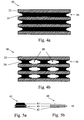
- Fig. 4a shows a cross sectional view of a first embodiment of a suspension element 30.
- Suspension element 30 has a flat laminate sandwich structure with several metal layers 33 and elastomer layers 34 sandwiched there between. Each of the elastomer layers 34 has a recess 36 at its outer edge. When elastomer layer 34 is compressed during operation, the bulk elastomer can extend into that recess. Thus, the risk of damage of the elastomer layer surface is reduced and the fatigue strength of the suspension element 30 is improved.
- FIG. 4b A cross sectional view of another embodiment of a suspension element 30 is shown in Fig. 4b.
- the suspension element 30 shown in Fig. 4b comprises several cavities 38 within elastomer layers 34.
- the size and distribution of cavities 38 may be adapted, e.g. by computer modeling of the dynamic behavior of elastomer layer 34. It should be understood that the elastomer layer becomes the softer the more area of it is occupied with cavities 38.
- the fraction of cavities within an elastomer layer 34 can be used to shape the stiffness curve of that layer and, accordingly, of the suspension element.
- the cavities may cover up to 50 % of the area of the elastomer layer. Typically, the area covered by these cavities is in the range from 1 % to 50 %, typically within 10 % to 40 % or 15 % to 30 % of the total area of the elastomer layer 34.
- FIG. 4b A further feature of a suspension element can be seen in Fig. 4b.
- the cross sectional view shows that the elastomer material is recessed along the edges of cavities 38.
- the elastomer material can extend into these recesses when the elastomer layer 34 is compressed.
- the volume of the elastomer is further reduced and, thus, elastomer layer 34 further softened.
- Figs. 5a and 5b show displacement limiting elements, i.e. displacement limiting elements, according to embodiments of the present invention. Their principal structure is very similar to the structure of a suspension element, i.e. displacement limiting elements are also laminates from metal and elastomer layers and the elastomer layer typically comprises at least one of the following materials: natural rubber, acrylic rubber, butadiene rubber, butyl rubber, chloroprene, chlorinated polyethylene, ethylene-propylene-diene, fluorosilicone rubber, fluorocarbon rubber, nitrile rubber, polyethylen, polyvinyl chloride, polymethyl methacrylate, polybutabiene, polypropylene, polyisobutylene, polyurethane, polyvinyl acetate, polyisoprene, styrene butadiene, silicone rubber, urethane rubber.
- natural rubber acrylic rubber, butadiene rubber, butyl rubber, chloroprene, chlorinated
- displacement limiting elements differ from suspension elements in that they have high dynamic stiffness and high dynamic damping to realize both displacement control and energy dissipation during extreme loads.
- the displacement limiting elements have a dynamic stiffness in the range from about 100 kN/mm up to about 50000 kN/mm and a dynamic damping loss in the range from about 5 % to about 25 %.
- the stiffness curve of the displacement limiting elements is non-linear.
- different types of displacement limiting elements may be provided, e.g. softer displacement limiting elements 45 disposed in directions of relatively low forces and harder displacement limiting elements 40 disposed in directions of high loads.
- the dynamic stiffness curves of the displacement limiting elements can be individually shaped for each application.
- displacement limiting elements may have a very thick elastomer layer for contacting the suspended apparatus.
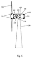
- the nacelle of the wind turbine comprises an outer steel frame 100 and an inner steel frame 110 which houses a gear box 300 and a generator 400.
- the outer steel frame 100 is mounted on top of a tower 200.
- the wind turbine has rotor blades 500 mounted to a hub.
- Suspension elements 130 are mounted between the inner corners of outer frame 100 and the outer corners of inner frame 110 so that inner frame 110 is completely dynamically insulated from outer frame 100. Thus, vibrations of inner frame 110 are not transferred to outer frame 100.
- gear box 300 is suspended by suspension elements 330 inside inner frame 110 as well as generator 400 is suspended by suspension elements 430 inside inner frame 110.
- gear box 300 and generator 400 are decoupled from inner frame 110.
- the bearing of the nacelle is suspended on suspension elements 230 disposed at the top of steel tower 200 so that vibrations of the nacelle, i.e. vibrations of outer frame 100 in this case, are not transferred to steel tower 200.
- rotor blades 500 are suspended by suspension elements 530 to isolate them from the hub. Due to these measures, the noise, particularly the audible noise, emitted from the wind turbine is considerably reduced. It should further be understood that, of course, displacement limiting elements can also be provided for inner frame 110, gear box 300 and/or generator 400.
Landscapes
- Engineering & Computer Science (AREA)
- General Engineering & Computer Science (AREA)
- Mechanical Engineering (AREA)
- Combustion & Propulsion (AREA)
- Chemical & Material Sciences (AREA)
- Physics & Mathematics (AREA)
- Architecture (AREA)
- Acoustics & Sound (AREA)
- Aviation & Aerospace Engineering (AREA)
- Life Sciences & Earth Sciences (AREA)
- Sustainable Development (AREA)
- Sustainable Energy (AREA)
- Vibration Prevention Devices (AREA)
Abstract
Description
- The present invention relates to a suspension system and to a wind turbine comprising the suspension system.
- Noise emission from technical installations, particularly power systems, is a safety and environmental concern. Legislation dictates the admissible sound pressure level that a noise source in a certain location may continuously make so that reduced noise emission is a key requirement for low impact environmental integration. Regulations governing these levels vary currently from country to country. In Europe, European Directives 2000-194-EC and 2002-49-EC provide standards. In Germany, the standard values are based on VDI standard 2058, and were adopted by the Technical Directive on Noise Abatement prescribed by law. The maximum allowable values depend on the character of the surroundings and the time of day. For example, 65 dB(A) are allowed in a prevailing industrial surrounding during the day, whereas only 35 dB(A) are allowed in exclusively residential surroundings during the night. These regulations define environmental requirements and acoustical targets for wind turbine installations.
- Noise generated by wind turbines is partly mechanical, and partly aerodynamic. Mechanical noise is generated mainly from machinery in the nacelle, particularly the gearbox and the generator, although there may also be contributions from cooling fans, auxiliary equipment (such as pumps and compressors), bearings and the yaw system. Machinery noise is related to high frequency dynamic forces than can generate structure borne or air-borne mechanical noise. Therein, the low frequency noise associated with high forces can be assigned to static and quasi-static loads, e.g. the rotor power torque caused by the wind. Quasi-static structural dynamics being typically below 20Hz does not relate to noise generation but structural fatigue. High frequency structure-borne mechanical noise, typically in the frequency range of 20-1000Hz is often associated to dynamic forces related to gear pair meshing mechanical forces from mechanical gear systems or stator-rotor pole meshing electrostatic forces from electrical generator systems. Because dynamic forces from machinery correspond to a discrete force spectrum described by meshing frequencies, the noise spectrum related can also be discrete in nature and result in tonal noise components.
- Structure-borne mechanical noise is therefore initiated by dynamic forces from machinery where these dynamic forces are injected by mechanical gear or generator systems at machinery mounting interfaces into the supporting structures or chassis. Transferred dynamic forces through chassis response can then excite structural vibration modes from larger structures such as tower, blades and nacelle enclosure. By coupling with surrounding air, the vibrating surfaces generate sound radiation. Force transfer and noise radiation are especially effective when structural resonances are matching along the transfer chain and when the structural modes wavelength matches the acoustic wavelength in air related to acoustic radiation maxima.
- Therefore, damping or isolation of the machinery vibrations are desirable. Another attempt is described in
DE 199 30 751 A1 by F. Mitsch filed July 2, 1999 , disclosing a method for reducing vibrations of components of a wind turbine. According to said method, a plurality of bearings made of a very soft elastomeric material are used for damping the vibrations. Also, cylindrical elastomeric bushings are used for vibration isolation in existing wind turbines. However, cylindrical elastomer bushings have several disadvantages, namely that they are highly non-linear elements and, therefore, become dynamically hard as steel if high loads are applied. Furthermore, elastomer bushings exhibit poor vibration isolation over the entire frequency range due to their cylindrical shape and their dynamic stiffness increase with frequency. Moreover, the vibration isolation ability of elastomer bushings rapidly decreases with environmental temperature. A further drawback of standard cylindrical elastomer bushings is that they only operate providing low dynamic stiffness and hence some vibration isolation potential along the radial axis direction and allow only very small lateral displacement, thus enabling only very low isolation on the other axis because of typically high radial dynamic stiffness incompatible with vibration isolation. - An additional aspect of vibration isolation is that the machinery support must be able to withstand high loads caused by high wind speeds or wind gusts. Therefore, a conflict exists between vibration isolation requiring very soft mounts to provide vibration isolation for noise control purpose and very hard mounts that can sustain high loads and allow only small displacements of the machinery.
- It is therefore an object of the present invention to provide a vibration isolating suspension system that overcomes the above mentioned problems associated with the prior art at least partially. Furthermore, it is an object of the present invention to provide a wind turbine with an improved suspension system.
- This object is solved by a suspension system according to claim 1. Further aspects, advantages, features, and details of the present invention are apparent from the dependent claims, the description and the accompanying drawings.
- According to a first aspect of the present invention, a suspension system for suspending an apparatus is provided, the suspension system comprising at least one suspension element mountable between the apparatus and a support, wherein said suspension element comprises a laminate material having at least one metal layer and at least one elastomer layer laminated thereon.
- A laminated suspension element as described above acts like a spring and shows constant linear dynamic stiffness for either pure compression, pure shear or even a combination thereof. Typically, the suspension element will have a rather flat geometry which further enhances these properties compared to the cylindrical elastomer bushings. Thus, the suspension element provides high vibration isolation at any given load. In contrast to standard elastomer bushings, the dynamic behavior of the above described suspension element can be easily predicted and modeled.
- According to an embodiment of the present invention, the suspension element has low dynamic stiffness and low dynamic damping to realize high vibration isolation by dynamically decoupling the apparatus relatively to its supporting structure. Therefore, the suspension element will typically have a dynamic stiffness in the range from about 10 kN/mm up to about 500 kN/mm and a dynamic damping loss in the range from about 1 % to about 5 %. To make the elastomer layer softer, specific molding patterns like longitudinal or lateral stripes extending through the elastomer layer may be provided. Typically, these specific molding patterns are formed as cavities and may cover up to 50 % of the area of the elastomer layer. Typically, the area covered by these molding patterns is in the range from 1 % to 50 %, typically within 10 % to 40 % or 15 % to 30 % of the total area of the elastomer layer. The molding patterns can increase the elastomer expansion or deformation area under compression or shear load.
- According to another embodiment of the present invention, the suspension system comprises also at least one displacement limiting element (also called a bump stop) which is mountable to the support and dimensioned to be spaced from the apparatus by a clearance when being mounted to the support, wherein the at least one displacement limiting element comprises a laminate material having at least one metal layer and at least one elastomer layer laminated thereon.
- The additional displacement limiting element elements are fixed to the support and are not in contact with the apparatus during normal operation since the vibrational displacement of the apparatus during normal operation is smaller than the clearance. However, when high loads occur, e.g. normal short term high wind gusts or exceptional events like extreme wind gusts, emergency stops, cross-bar events or the like, the displacement limiting elements limit the lateral or vertical displacement of the apparatus. Typically, the displacement limiting elements will therefore have high dynamic stiffness and high dynamic damping to realize both displacement control and energy dissipation during extreme loads. Typically, the displacement limiting elements or displacement limiting elements have a dynamic stiffness in the range from about 100 kN/mm up to about 50000 kN/mm and a dynamic damping loss in the range from about 5 % to about 25 %. Typically, the stiffness curve of the displacement limiting elements is non-linear.
- According to another embodiment of the present invention, the suspension system includes at least two suspension elements, wherein the surface normal of each of the suspension elements is angled at an angle α in a range from 0° ≤ α ≤ 90° with respect to the direction of the main load applied to the apparatus. Typically, an angle in the range from 20° to 70° is selected. By providing the suspension element angled with respect to the direction of the main load, a combination of shear loads and compression loads will be applied to the suspension element.
- According to a further embodiment of the present invention, the suspension elements and/or the displacement limiting elements have several sandwiched metal and/or elastomer layers. Typically, the metal layers are individually tailored to a specific frequency whereas the elastomer layers are individually tailored to a specific stiffness curve. In this context, it should be understood that the different metal layers of a single element may be formed of different metals. Likewise, the different elastomer layers of a single element may be formed of different elastomers. Thus, the laminated sandwich elastomer elements can be tailored to a multiple step stiffness curve and several tuning frequencies, e.g. by applying a cascaded mass-spring circuit model. Also, the suspensions elements and/or the displacement limiting elements may be thermally insulated to maintain a specific stiffness.
- According to another aspect of the present invention, a wind turbine comprising at least one of the afore-mentioned suspension systems is provided. Typically, the wind turbine machinery suspended by the suspension system is a blade bearing, an inner nacelle frame, a tower bearing, a gear box, a generator, or a shaft bearing. However, every other machinery may be suspended with a suspension system as described above.
- A full and enabling disclosure of the present invention, including the best mode thereof, to one of ordinary skill in the art, is set forth more particularly in the remainder of the specification, including reference to the accompanying figures wherein:
- Fig. 1
- is a schematic view of a suspension system according to an embodiment of the present invention.
- Fig. 2
- is a cross-sectional view of a suspension system according to another embodiment of the present invention.
- Figs. 3a and 3b
- show cross-sectional views of further embodiments of the present invention.
- Figs. 4a and 4b
- show suspension elements according to embodiments of the present invention.
- Figs. 5a and 5b
- show displacement limiting elements according to embodiments of the present invention.
- Fig. 6
- is a schematic view of a wind turbine equipped with suspension elements according to embodiments of the present invention.
- Reference will now be made in detail to the various embodiments of the invention, one or more examples of which are illustrated in the figures. Each example is provided by way of explanation of the invention, and is not meant as a limitation of the invention. For example, features illustrated or described as part of one embodiment can be used on or in conjunction with other embodiments to yield yet a further embodiment. It is intended that the present invention includes such modifications and variations.
- Fig. 1 is a schematic view of a suspension system according to an embodiment of the present invention. Therein, a
suspension element 30 is mounted between anapparatus 10 and asupport 20. Theapparatus 10 vibrates, i.e. is displaced, in Z- as well as in Y-direction as indicated by the arrows. Thesuspension element 30 dynamically decouples theapparatus 10 from thesupport 20 so that the vibrations of the apparatus are not or only to a small degree transferred to support 20. For this purpose,suspension element 30 is formed as a laminate material comprising ametal layer 32 and anelastomer layer 34. Typically, the elastomer layer comprises at least one of the following materials: natural rubber, acrylic rubber, butadiene rubber, butyl rubber, chloroprene, chlorinated polyethylene, ethylene-propylene-diene, fluorosilicone rubber, fluorocarbon rubber, nitrile rubber, polyethylen, polyvinyl chloride, polymethyl methacrylate, polybutabiene, polypropylene, polyisobutylene, polyurethane, polyvinyl acetate, polyisoprene, styrene butadiene, silicone rubber, urethane rubber. Thesuspension element 30 is essentially flat, i.e. its thickness, which is typically in the range between 10 mm to 500 mm, is considerably smaller than its lateral extensions and has low dynamic stiffness and low dynamic damping to realize high vibration isolation by dynamically decoupling theapparatus 10 relatively to its supporting structure. Therefore, the suspension element will typically have a dynamic stiffness in the range from about 10 kN/mm up to about 500 kN/mm and a dynamic damping loss in the range from about 1 % to about 5 %. As is apparent from Fig. 1, displacements ofapparatus 10 in the Z-direction act as compressions/decompressions ontosuspension element 30 whereas displacements ofapparatus 10 in the Y-direction act as shear ontosuspension element 30. Due to its specific structure,suspension element 30 exhibits a linear dynamic stiffness over a large range of loads. - As an optional feature, a
displacement limiting element 40 is shown in broken lines in Fig. 1. Thisdisplacement limiting element 40 has a structure similar to thesuspension element 30, i.e. the displacement limiting element comprises also at least one metal layer and at least one elastomer layer. However, additionaldisplacement limiting element 40 is fixed to the support but is not in contact with the apparatus during normal operation. Particularly, a clearance exists betweendisplacement limiting element 40 andapparatus 10. The size of the clearance is such that the vibrational displacement of theapparatus 10 during normal operation is smaller than the clearance so that the apparatus does not contactdisplacement limiting element 40 during normal operation. However, when high loads occur, e.g. during emergency stops, cross-bar events or extreme wind gusts,displacement limiting element 40 effectively limits the vertical displacement ofapparatus 10. Typically, the displacement limiting element will therefore have high dynamic stiffness and high dynamic damping to realize both displacement control and energy dissipation during extreme loads. Typically,displacement limiting element 40 has a dynamic stiffness in the range from about 100 kN/mm up to about 50000 kN/mm and a dynamic damping loss in the range from about 5 % to about 25 %. Typically, the stiffness curve of the displacement limiting element is non-linear. Of course, also further displacement limiting elements could be provided, e.g. for limiting the lateral movement ofapparatus 10 in the Y-direction. - Fig. 2 is a cross-sectional view of a suspension system according to another embodiment of the present invention. Therein, a rotating
shaft 10 is supported in asteel bearing 11. The rotatingshaft 11 may be connected to a rotor of a wind turbine. Thebearing 11 is suspended by foursuspension elements 30 mounted between the bearing 11 and a support formed by asteel frame displacement limiting elements steel frame 20 between each of the suspension elements. Aclearance 41 exists between each of thedisplacement limiting elements bearing 11. The size ofclearance 41 is such that bearing I 1 will not contact any ofdisplacement limiting elements - As shown in Fig. 2,
shaft 10 applies a torque Mx as well as vertical loads Fz and lateral loads Fy onto bearing 11. Due to these operational forces,shaft 10 andbearing 11 are displaced by vibrational motion. Sincesuspension elements 30 dynamically decoupleshaft 10 and bearing 11 fromsteel frame 20, the vibrations ofshaft 10 andbearing 11 are not transferred to frame 20. Thus, noise emission fromouter steel frame 20 is effectively suppressed. - In the arrangement shown in Fig. 2, the suspension elements are angled about an angle α with respect to the main load directions as will be explained in the following with reference to
suspension elements Bearing 11 has an octagonal shape with faces being normal to the main load directions and tapered faces in between.Steel frame 20 has a rectangular cross section with the faces of the rectangle being normal to the main load directions. However, taperedabutments 21 are disposed onsteel frame 20, the tapered faces of theabutments 21 being parallel to the tapered faces of thebearing 11.Suspension elements abutments 21 and the tapered faces of bearing 11. Thus,suspension elements system forcing shaft 10 back to its original position. It should be understood that, of course, suspension elements can also be provided in the X-direction, thus making the system of Fig. 2 a 3-axis suspension system. However, the system can also be configured as a 1-axis suspension system by setting the angle α = 0° degrees. - In Fig. 2, the arrows indicate that the vertical loads Fz, e.g. resulting from a teetering motion of the wind turbine rotor, are larger than the lateral loads Fy, e.g. resulting from a yaw motion of the wind turbine rotor. Therefore, the angle α of
abutments 21 is not 45° but smaller so that the suspension elements are more horizontally positioned. Thus, the suspension elements react more compressively in the high load Z-direction and more shear-like in the Y-direction. Furthermore, thedisplacement limiting elements 40 in the high load Z-direction are different to thedisplacement limiting elements 45 in the Y-direction.Displacement limiting elements 40 in the high load Z-direction are designed to withstand higher loads thandisplacement limiting elements 45 in the Y-direction. Additionally or alternatively, theclearance 41 betweendisplacement limiting elements 40 andbearing 11 may be larger than betweendisplacement limiting elements 45 andbearing 11. - Figs. 3a and 3b show cross-sectional views of other embodiments of the present invention. Therein, two suspension systems are shown which have a similar structure to the suspension system shown in Fig. 2 are provided. These suspension systems are mounted on a structure or support. The machinery has shafts which extend into the suspension systems and, thus, the machinery is suspended. In both cases, the machinery has larger dimensions than the suspension systems. According to the embodiment shown in Fig. 3a, the machinery is suspended on its bottom side whereas, according to the embodiment shown in Fig. 3b, the machinery can be suspended on its horizontal axis since the structure has a recess in which the machinery can extend. Although only two suspension systems are shown in the cross-sectional views of Figs. 3a and 3b, it should be understood that also four suspension systems can be used in these embodiments. As is apparent from Figs. 3a and 3b, the suspension systems are disposed in front of the machinery. Likewise, two more suspension systems may be disposed in a similar manner behind the machinery. Thus, symmetry and redundancy of the arrangement is improved and the individual suspension systems may have smaller dimensions.
- Next, a
suspension element 30 is explained in detail with reference to Figs. 4a and 4b. Fig. 4a shows a cross sectional view of a first embodiment of asuspension element 30.Suspension element 30 has a flat laminate sandwich structure withseveral metal layers 33 andelastomer layers 34 sandwiched there between. Each of the elastomer layers 34 has arecess 36 at its outer edge. Whenelastomer layer 34 is compressed during operation, the bulk elastomer can extend into that recess. Thus, the risk of damage of the elastomer layer surface is reduced and the fatigue strength of thesuspension element 30 is improved. - A cross sectional view of another embodiment of a
suspension element 30 is shown in Fig. 4b. Although the basic design is similar to the embodiment shown in Fig. 4a, thesuspension element 30 shown in Fig. 4b comprisesseveral cavities 38 within elastomer layers 34. The size and distribution ofcavities 38 may be adapted, e.g. by computer modeling of the dynamic behavior ofelastomer layer 34. It should be understood that the elastomer layer becomes the softer the more area of it is occupied withcavities 38. Thus, the fraction of cavities within anelastomer layer 34 can be used to shape the stiffness curve of that layer and, accordingly, of the suspension element. The cavities may cover up to 50 % of the area of the elastomer layer. Typically, the area covered by these cavities is in the range from 1 % to 50 %, typically within 10 % to 40 % or 15 % to 30 % of the total area of theelastomer layer 34. - A further feature of a suspension element can be seen in Fig. 4b. The cross sectional view shows that the elastomer material is recessed along the edges of
cavities 38. Thus, the elastomer material can extend into these recesses when theelastomer layer 34 is compressed. Also, the volume of the elastomer is further reduced and, thus,elastomer layer 34 further softened. - Figs. 5a and 5b show displacement limiting elements, i.e. displacement limiting elements, according to embodiments of the present invention. Their principal structure is very similar to the structure of a suspension element, i.e. displacement limiting elements are also laminates from metal and elastomer layers and the elastomer layer typically comprises at least one of the following materials: natural rubber, acrylic rubber, butadiene rubber, butyl rubber, chloroprene, chlorinated polyethylene, ethylene-propylene-diene, fluorosilicone rubber, fluorocarbon rubber, nitrile rubber, polyethylen, polyvinyl chloride, polymethyl methacrylate, polybutabiene, polypropylene, polyisobutylene, polyurethane, polyvinyl acetate, polyisoprene, styrene butadiene, silicone rubber, urethane rubber.
- However, displacement limiting elements differ from suspension elements in that they have high dynamic stiffness and high dynamic damping to realize both displacement control and energy dissipation during extreme loads. Typically, the displacement limiting elements have a dynamic stiffness in the range from about 100 kN/mm up to about 50000 kN/mm and a dynamic damping loss in the range from about 5 % to about 25 %. Typically, the stiffness curve of the displacement limiting elements is non-linear. Furthermore, different types of displacement limiting elements may be provided, e.g. softer
displacement limiting elements 45 disposed in directions of relatively low forces and harderdisplacement limiting elements 40 disposed in directions of high loads. Like the suspension elements, the dynamic stiffness curves of the displacement limiting elements can be individually shaped for each application. Furthermore, displacement limiting elements may have a very thick elastomer layer for contacting the suspended apparatus. - Finally, possible applications of the suspension system to a wind turbine are shown in Fig. 6. Therein, the nacelle of the wind turbine comprises an
outer steel frame 100 and aninner steel frame 110 which houses agear box 300 and agenerator 400. Theouter steel frame 100 is mounted on top of atower 200. Furthermore, the wind turbine hasrotor blades 500 mounted to a hub.Suspension elements 130 are mounted between the inner corners ofouter frame 100 and the outer corners ofinner frame 110 so thatinner frame 110 is completely dynamically insulated fromouter frame 100. Thus, vibrations ofinner frame 110 are not transferred toouter frame 100. Furthermore,gear box 300 is suspended bysuspension elements 330 insideinner frame 110 as well asgenerator 400 is suspended bysuspension elements 430 insideinner frame 110. Thus,gear box 300 andgenerator 400 are decoupled frominner frame 110. Likewise, the bearing of the nacelle is suspended onsuspension elements 230 disposed at the top ofsteel tower 200 so that vibrations of the nacelle, i.e. vibrations ofouter frame 100 in this case, are not transferred tosteel tower 200. Finally, alsorotor blades 500 are suspended bysuspension elements 530 to isolate them from the hub. Due to these measures, the noise, particularly the audible noise, emitted from the wind turbine is considerably reduced. It should further be understood that, of course, displacement limiting elements can also be provided forinner frame 110,gear box 300 and/orgenerator 400. - Having thus described the invention in detail, it should be apparent for a person skilled in the art that various modifications can be made in the present invention without departing from the spirit and scope of the following claims. For example, it should be clear that, although described with respect to a wind turbine, the above described suspension system can be used for suspending any vibrating or moving machinery, e.g. on ships, aircraft or land transportation means. Furthermore, the suspension elements and/or the displacement limiting elements may be provided with thermal insulation to maintain a relatively constant operational temperature. Thus, the specific stiffness properties of the elastomer can be maintained during operation.
Claims (13)
- A suspension system for suspending an apparatus, comprising
at least one suspension element (30) mountable between the apparatus (10,11) and a support (20, 21), wherein said suspension element comprises a laminate material having at least one metal layer (32) and at least one elastomer layer (34) laminated thereon. - The suspension system according to claim 1, wherein the at least one suspension element (30) has a dynamic stiffness in the range from about 10 kN/mm up to about 500 kN/mm and a dynamic damping loss in the range from about 1 % to about 5 %.
- The suspension system according to any of the preceding claims, wherein the at least one elastomer layer (34) comprises at least one cavity (38).
- The suspension system according to claim 3, wherein up to 50 % of the area of the elastomer layer (34) are covered by a cavity or a plurality of cavities.
- The suspension system according to any of the preceding claims, further comprising at least one displacement limiting element (40) mountable to the support (20, 21) and dimensioned to be spaced from the apparatus (10, 11) by a clearance (41) when being mounted to the support (20, 21), wherein the at least one displacement limiting element (40) comprises a laminate material having at least one metal layer (42) and at least one elastomer layer (43, 44) laminated thereon.
- The suspension system according to claim 5, wherein the at least one displacement limiting element (40) has a dynamic stiffness in the range from about 100 kN/mm up to about 50000 kN/mm and a dynamic damping loss in the range from about 5 % to about 25 %.
- The suspension system according to any of the preceding claims, wherein the elastomer layer (34) of the suspension element (30) and/or the elastomer layer (43, 44) of the displacement limiting element (40) comprise a recess (36, 46) at their respective outer edge and/or on the edge a cavity (38) within the elastomer layer (34, 43, 44).
- The suspension system according to any of the preceding claims, wherein the suspension element (30) and/or the displacement limiting element comprise a plurality of laminated metal and elastomer layers (32, 34; 42, 43, 44).
- The suspension system according to any of the preceding claims, wherein the elastomer layers (34, 43, 44) comprise at least one of the following materials: natural rubber, acrylic rubber, butadiene rubber, butyl rubber, chloroprene, chlorinated polyethylene, ethylene-propylene-diene, fluorosilicone rubber, fluorocarbon rubber, nitrile rubber, polyethylen, polyvinyl chloride, polymethyl methacrylate, polybutabiene, polypropylene, polyisobutylene, polyurethane, polyvinyl acetate, polyisoprene, styrene butadiene, silicone rubber, urethane rubber.
- The suspension system according to any of the preceding claims, comprising at least two suspension elements (31, 32), wherein the surface normal of each of the suspension elements (31, 32) is angled in a range from 0° to 90° with respect to the direction of the main load (Fz) applied to the apparatus (10, 11).
- The suspension system according to any of the preceding claims, wherein at least one of said suspension elements (30, 31, 32) and/or displacement limiting elements (40, 45) has a thermal insulation.
- A wind turbine comprising at least one suspension system according to any of the preceding claims.
- The wind turbine according to claim 12, wherein the apparatus suspended by the suspension system is a blade bearing, an inner nacelle frame, a tower bearing, a gear box, a generator, or a shaft bearing.
Priority Applications (4)
| Application Number | Priority Date | Filing Date | Title |
|---|---|---|---|
| EP20050016089 EP1748216B1 (en) | 2005-07-25 | 2005-07-25 | Suspension system |
| DK05016089.4T DK1748216T3 (en) | 2005-07-25 | 2005-07-25 | Suspension System |
| US11/459,151 US7819624B2 (en) | 2005-07-25 | 2006-07-21 | Suspension system |
| CN2006101257831A CN1904406B (en) | 2005-07-25 | 2006-07-25 | Suspension device and wind turbine with the suspension device |
Applications Claiming Priority (1)
| Application Number | Priority Date | Filing Date | Title |
|---|---|---|---|
| EP20050016089 EP1748216B1 (en) | 2005-07-25 | 2005-07-25 | Suspension system |
Publications (2)
| Publication Number | Publication Date |
|---|---|
| EP1748216A1 true EP1748216A1 (en) | 2007-01-31 |
| EP1748216B1 EP1748216B1 (en) | 2015-04-22 |
Family
ID=35677291
Family Applications (1)
| Application Number | Title | Priority Date | Filing Date |
|---|---|---|---|
| EP20050016089 Expired - Lifetime EP1748216B1 (en) | 2005-07-25 | 2005-07-25 | Suspension system |
Country Status (4)
| Country | Link |
|---|---|
| US (1) | US7819624B2 (en) |
| EP (1) | EP1748216B1 (en) |
| CN (1) | CN1904406B (en) |
| DK (1) | DK1748216T3 (en) |
Cited By (3)
| Publication number | Priority date | Publication date | Assignee | Title |
|---|---|---|---|---|
| WO2015155131A1 (en) * | 2014-04-07 | 2015-10-15 | Wobben Properties Gmbh | Nacelle of a wind turbine |
| EP3012479A1 (en) * | 2014-10-24 | 2016-04-27 | FM Energie GmbH & Co. KG | Elastic multi-edge bearing for wind power plants |
| EP3739227B1 (en) * | 2019-04-30 | 2023-01-25 | General Electric Company | Bearing for a wind turbine drivetrain having an elastomer support |
Families Citing this family (31)
| Publication number | Priority date | Publication date | Assignee | Title |
|---|---|---|---|---|
| US8262051B2 (en) * | 2007-08-23 | 2012-09-11 | Raytheon Company | Z-leg shock isolator |
| US20090107567A1 (en) * | 2007-10-26 | 2009-04-30 | Crary Peter B | Combination water tower and electrical wind turbine generator |
| EP2072975A1 (en) * | 2007-12-19 | 2009-06-24 | Siemens Aktiengesellschaft | Method and apparatus for vibration-based automatic condition monitoring of a wind turbine |
| GB0810678D0 (en) * | 2008-06-11 | 2008-07-16 | Black & Decker Inc | Resilient stop assembly for impact tool |
| ES2746975T3 (en) * | 2008-10-03 | 2020-03-09 | Ge Renewable Tech Wind Bv | Procedure and system to align a component of a wind turbine |
| CN101725482B (en) * | 2009-12-30 | 2012-06-20 | 洛阳双瑞橡塑科技有限公司 | Damping composite type variable rigidity vibration attenuating support for gearbox of wind powered generator |
| US8746663B2 (en) | 2010-01-19 | 2014-06-10 | Fm Energie Gmbh & Co. Kg | Elastomer spring with mechanically adjustable stiffness |
| JP5257418B2 (en) * | 2010-07-23 | 2013-08-07 | 株式会社デンソー | Connection structure for vibration isolation target members |
| EP2436946B1 (en) * | 2010-09-29 | 2013-08-21 | Carl Freudenberg KG | Heating element for oscillation-based components |
| CN102146975B (en) * | 2011-01-27 | 2013-02-13 | 同济大学 | Damping device and wind power generation tower using same |
| CN102174929B (en) * | 2011-03-24 | 2012-10-03 | 中国船舶重工集团公司第七一一研究所 | Wind generating set gear box elastic support device convenient to disassemble and adjust |
| US20130259684A1 (en) * | 2012-03-28 | 2013-10-03 | General Electric Company | Systems and methods for attenuating noise in a wind turbine |
| DE102012205090A1 (en) | 2012-03-29 | 2013-10-02 | Repower Systems Se | Gearbox mounting of a wind turbine, wind turbine and method for servicing a gearbox mounting |
| DE102012205086A1 (en) | 2012-03-29 | 2013-10-02 | Repower Systems Se | Gearbox mounting of a wind turbine, wind turbine and method for servicing a gearbox mounting |
| DE102012009850A1 (en) * | 2012-05-21 | 2013-11-21 | Hartwig Schwieger | Wind energy plant, has foundation, mast, nacelle, and vertically or horizontally rotatably mounted wind rotor, where vibration-resilient connection is provided between mast structure and foundation by large construction bottom plate |
| ES2727949T3 (en) * | 2012-09-13 | 2019-10-21 | Esm Energie Und Schwingungstechnik Mitsch Gmbh | Elastic swing bearing |
| CN103322118B (en) * | 2013-07-11 | 2014-12-10 | 广西科技大学 | Broadband dynamic vibration absorber |
| DK2884095T3 (en) * | 2013-12-12 | 2016-11-28 | Siemens Ag | Adjusted liquid damper of a wind turbine |
| DE102014206703A1 (en) * | 2014-04-07 | 2015-10-08 | Wobben Properties Gmbh | Gondola of a wind turbine |
| EP2975260B2 (en) * | 2014-07-18 | 2021-12-22 | Siemens Gamesa Renewable Energy A/S | Generator suspension arrangement |
| CN104165127A (en) * | 2014-08-09 | 2014-11-26 | 常州市武进华瑞电子有限公司 | Shock-proof wind turbine |
| EP3208492B1 (en) * | 2014-10-17 | 2019-04-10 | Bridgestone Corporation | Anti-vibration device |
| CN105003635B (en) * | 2015-06-02 | 2018-01-09 | 株洲时代新材料科技股份有限公司 | Support meanss and installation method and maintaining method for gear-box |
| CN105927706A (en) * | 2016-07-06 | 2016-09-07 | 西南交通大学 | Transverse connection vibration reducing device between vehicle lower hanging parts |
| EP3269997B1 (en) * | 2016-07-14 | 2020-01-01 | Siemens Gamesa Renewable Energy A/S | Oscillation absorber for a structure |
| CN107061616A (en) * | 2017-03-29 | 2017-08-18 | 贵州大学 | A kind of haulage vehicle power transmission shaft damping sound arrester |
| US20190338675A1 (en) * | 2018-05-01 | 2019-11-07 | General Electric Company | Variable Stiffness Structural Member |
| CN109764082A (en) * | 2019-01-09 | 2019-05-17 | 宁波拓普集团股份有限公司 | A kind of dynamic vibration absorber |
| EP4352377A1 (en) * | 2021-06-07 | 2024-04-17 | EFFBE GmbH | Elastomeric spring and azimuth drive with elastomeric spring |
| DE102021116293A1 (en) | 2021-06-07 | 2022-12-08 | Effbe Gmbh | Elastomer spring and azimuth drive with elastomer spring |
| JP7581270B2 (en) | 2022-02-22 | 2024-11-12 | 株式会社東芝 | Vibration control system and vibration control method |
Citations (8)
| Publication number | Priority date | Publication date | Assignee | Title |
|---|---|---|---|---|
| GB745020A (en) * | 1953-11-25 | 1956-02-15 | Metalastik Ltd | Improvements in or relating to axle box mountings |
| GB1454145A (en) * | 1973-12-06 | 1976-10-27 | Jorn R | Resilient mounting |
| US4406094A (en) * | 1980-02-28 | 1983-09-27 | Messerschmitt-Boelkow-Blohm Gesellschaft Mit Beschraenkter Haftung | Apparatus for anchoring self-supporting, tall structures |
| EP1008747A2 (en) * | 1998-12-08 | 2000-06-14 | Franz Mitsch | Vibration absorber for wind turbines |
| DE19930751A1 (en) | 1999-07-02 | 2001-01-04 | Franz Mitsch | Process for reducing vibrations in wind turbines |
| US20030164586A1 (en) * | 2002-03-04 | 2003-09-04 | Michael Robert J. | Mount with dual stiffness |
| DE10212075A1 (en) * | 2002-03-19 | 2003-10-09 | Nordseewerke Gmbh | Drive mounting comprises conventional spring unit, above which is mounted packet comprising four steel plates and at least three rubber plates arranged alternately along direction of load |
| EP1384915A2 (en) * | 2002-07-26 | 2004-01-28 | Audi Ag | Elastic mount |
Family Cites Families (13)
| Publication number | Priority date | Publication date | Assignee | Title |
|---|---|---|---|---|
| US2661943A (en) * | 1951-02-15 | 1953-12-08 | Flexible Metals Corp | Resilient cushioning device |
| US2880885A (en) * | 1955-04-01 | 1959-04-07 | Nat Malleable & Steel Castings | Cushioning device |
| US3311331A (en) * | 1965-10-07 | 1967-03-28 | Lowell Ind Inc | Vibration absorbing combination |
| CH543357A (en) * | 1972-03-24 | 1973-10-31 | Kloeckner Humboldt Deutz Ag | Vibrating system for the production of moldings from granular masses |
| US4256354A (en) * | 1979-03-05 | 1981-03-17 | Barry Wright Corporation | Laminated bearing structures |
| US4291925A (en) * | 1979-07-26 | 1981-09-29 | Barry Wright Corporation | Laminated bearings with dual stock layers |
| US4329117A (en) * | 1980-04-22 | 1982-05-11 | United Technologies Corporation | Wind turbine with drive train disturbance isolation |
| US4357057A (en) * | 1981-07-27 | 1982-11-02 | Barry Wright Corporation | Laminated bearing with improved low temperature operating characteristics |
| US4744539A (en) * | 1987-01-21 | 1988-05-17 | Mack Trucks, Inc. | Vehicle mounting arrangement |
| JP3036297B2 (en) * | 1993-06-04 | 2000-04-24 | 神鋼電機株式会社 | Automatic transport vehicle |
| DK174404B1 (en) * | 1998-05-29 | 2003-02-17 | Neg Micon As | Wind turbine with vibration damper |
| US6382603B1 (en) * | 2001-02-08 | 2002-05-07 | Lockheed Martin Corporation | Ridged elastomer mount |
| US7220104B2 (en) * | 2004-12-30 | 2007-05-22 | General Electric Company | Vibration reduction system for a wind turbine |
-
2005
- 2005-07-25 DK DK05016089.4T patent/DK1748216T3/en active
- 2005-07-25 EP EP20050016089 patent/EP1748216B1/en not_active Expired - Lifetime
-
2006
- 2006-07-21 US US11/459,151 patent/US7819624B2/en not_active Expired - Fee Related
- 2006-07-25 CN CN2006101257831A patent/CN1904406B/en not_active Expired - Fee Related
Patent Citations (8)
| Publication number | Priority date | Publication date | Assignee | Title |
|---|---|---|---|---|
| GB745020A (en) * | 1953-11-25 | 1956-02-15 | Metalastik Ltd | Improvements in or relating to axle box mountings |
| GB1454145A (en) * | 1973-12-06 | 1976-10-27 | Jorn R | Resilient mounting |
| US4406094A (en) * | 1980-02-28 | 1983-09-27 | Messerschmitt-Boelkow-Blohm Gesellschaft Mit Beschraenkter Haftung | Apparatus for anchoring self-supporting, tall structures |
| EP1008747A2 (en) * | 1998-12-08 | 2000-06-14 | Franz Mitsch | Vibration absorber for wind turbines |
| DE19930751A1 (en) | 1999-07-02 | 2001-01-04 | Franz Mitsch | Process for reducing vibrations in wind turbines |
| US20030164586A1 (en) * | 2002-03-04 | 2003-09-04 | Michael Robert J. | Mount with dual stiffness |
| DE10212075A1 (en) * | 2002-03-19 | 2003-10-09 | Nordseewerke Gmbh | Drive mounting comprises conventional spring unit, above which is mounted packet comprising four steel plates and at least three rubber plates arranged alternately along direction of load |
| EP1384915A2 (en) * | 2002-07-26 | 2004-01-28 | Audi Ag | Elastic mount |
Cited By (3)
| Publication number | Priority date | Publication date | Assignee | Title |
|---|---|---|---|---|
| WO2015155131A1 (en) * | 2014-04-07 | 2015-10-15 | Wobben Properties Gmbh | Nacelle of a wind turbine |
| EP3012479A1 (en) * | 2014-10-24 | 2016-04-27 | FM Energie GmbH & Co. KG | Elastic multi-edge bearing for wind power plants |
| EP3739227B1 (en) * | 2019-04-30 | 2023-01-25 | General Electric Company | Bearing for a wind turbine drivetrain having an elastomer support |
Also Published As
| Publication number | Publication date |
|---|---|
| CN1904406B (en) | 2010-05-12 |
| CN1904406A (en) | 2007-01-31 |
| EP1748216B1 (en) | 2015-04-22 |
| DK1748216T3 (en) | 2015-07-27 |
| US7819624B2 (en) | 2010-10-26 |
| US20070090269A1 (en) | 2007-04-26 |
Similar Documents
| Publication | Publication Date | Title |
|---|---|---|
| EP1748216B1 (en) | Suspension system | |
| KR101523808B1 (en) | Noise-reducing device and method for reducing noise | |
| US4418898A (en) | Cushioned mounting device with a mass member forming a sub-oscillation system and means for restricting cushioning movement | |
| US11767105B2 (en) | Mount for supporting a component and attenuating noise | |
| JP2003526800A (en) | Active noise control system for defined space | |
| JP5584913B2 (en) | Floor structure | |
| CN101333939A (en) | Turbomachine shaft damper device | |
| US8602733B2 (en) | Structural and acoustical vibration dampener for a rotatable blade | |
| KR20120090773A (en) | Suspension structures | |
| CN119042263A (en) | Low-frequency vibration isolation metamaterial plate based on quasi-zero stiffness flexible beam | |
| KR19980071509A (en) | A noise reduction method of a rotary electric machine, an attachment device for implementing the method and attaching a stator to a rotary electric machine, and a rotary electric machine having an attachment device. | |
| CN113606274A (en) | Multi-degree-of-freedom local resonance type super-damping composite structure | |
| CN115596803B (en) | Vibration absorption and energy consumption combined broadband vibration damper suitable for aero-engine load-bearing frame | |
| US9248899B2 (en) | Soundproofing covering having resonators, a panel provided with the covering, and an aircraft | |
| US6224014B1 (en) | Device for reducing line noise inside a rotary-wing aircraft, especially a helicopter | |
| JP7046702B2 (en) | Damping support structure | |
| Lu et al. | Research on the vibration characteristics of a compounded periodic strut used for helicopter cabin noise reduction | |
| CN109404460B (en) | A Combined Laminated Friction Damping Vibration Absorber Under Magnetic Confinement | |
| WO2018092833A1 (en) | Vibration actuator mounting structure, electronic equipment provided with said vibration actuator mounting structure, and method for manufacturing vibration actuator mounting structure | |
| JP2000145889A (en) | Fastening structure of on-board mounted apparatus | |
| CN116502330A (en) | Underwater vehicle shell with vibration damping function and optimization method for shell vibration reduction | |
| Lee et al. | Vibration control of composite plates under random loading using piezoelectric material | |
| Lee et al. | Control of random vibrations of composite plates with piezoelectric actuators | |
| CN217294277U (en) | Shock-absorbing structure and car | |
| CN214196543U (en) | Wind turbine hub flexible structure and wind turbine |
Legal Events
| Date | Code | Title | Description |
|---|---|---|---|
| PUAI | Public reference made under article 153(3) epc to a published international application that has entered the european phase |
Free format text: ORIGINAL CODE: 0009012 |
|
| 17P | Request for examination filed |
Effective date: 20061012 |
|
| AK | Designated contracting states |
Kind code of ref document: A1 Designated state(s): AT BE BG CH CY CZ DE DK EE ES FI FR GB GR HU IE IS IT LI LT LU LV MC NL PL PT RO SE SI SK TR |
|
| AX | Request for extension of the european patent |
Extension state: AL BA HR MK YU |
|
| AKX | Designation fees paid |
Designated state(s): DE DK FI |
|
| 17Q | First examination report despatched |
Effective date: 20080214 |
|
| GRAP | Despatch of communication of intention to grant a patent |
Free format text: ORIGINAL CODE: EPIDOSNIGR1 |
|
| INTG | Intention to grant announced |
Effective date: 20141113 |
|
| GRAS | Grant fee paid |
Free format text: ORIGINAL CODE: EPIDOSNIGR3 |
|
| GRAA | (expected) grant |
Free format text: ORIGINAL CODE: 0009210 |
|
| AK | Designated contracting states |
Kind code of ref document: B1 Designated state(s): DE DK FI |
|
| REG | Reference to a national code |
Ref country code: DE Ref legal event code: R096 Ref document number: 602005046380 Country of ref document: DE Effective date: 20150603 |
|
| REG | Reference to a national code |
Ref country code: DK Ref legal event code: T3 Effective date: 20150721 |
|
| PG25 | Lapsed in a contracting state [announced via postgrant information from national office to epo] |
Ref country code: FI Free format text: LAPSE BECAUSE OF FAILURE TO SUBMIT A TRANSLATION OF THE DESCRIPTION OR TO PAY THE FEE WITHIN THE PRESCRIBED TIME-LIMIT Effective date: 20150422 |
|
| REG | Reference to a national code |
Ref country code: DE Ref legal event code: R097 Ref document number: 602005046380 Country of ref document: DE |
|
| PLBE | No opposition filed within time limit |
Free format text: ORIGINAL CODE: 0009261 |
|
| STAA | Information on the status of an ep patent application or granted ep patent |
Free format text: STATUS: NO OPPOSITION FILED WITHIN TIME LIMIT |
|
| 26N | No opposition filed |
Effective date: 20160125 |
|
| PGFP | Annual fee paid to national office [announced via postgrant information from national office to epo] |
Ref country code: DE Payment date: 20190827 Year of fee payment: 15 Ref country code: DK Payment date: 20190912 Year of fee payment: 15 |
|
| REG | Reference to a national code |
Ref country code: DE Ref legal event code: R119 Ref document number: 602005046380 Country of ref document: DE |
|
| REG | Reference to a national code |
Ref country code: DK Ref legal event code: EBP Effective date: 20200731 |
|
| PG25 | Lapsed in a contracting state [announced via postgrant information from national office to epo] |
Ref country code: DE Free format text: LAPSE BECAUSE OF NON-PAYMENT OF DUE FEES Effective date: 20210202 |
|
| PG25 | Lapsed in a contracting state [announced via postgrant information from national office to epo] |
Ref country code: DK Free format text: LAPSE BECAUSE OF NON-PAYMENT OF DUE FEES Effective date: 20200731 |