EP1748182A2 - Method and apparatus for replacing objects mounted on horizontal shafts in elevated locations - Google Patents
Method and apparatus for replacing objects mounted on horizontal shafts in elevated locations Download PDFInfo
- Publication number
- EP1748182A2 EP1748182A2 EP06253865A EP06253865A EP1748182A2 EP 1748182 A2 EP1748182 A2 EP 1748182A2 EP 06253865 A EP06253865 A EP 06253865A EP 06253865 A EP06253865 A EP 06253865A EP 1748182 A2 EP1748182 A2 EP 1748182A2
- Authority
- EP
- European Patent Office
- Prior art keywords
- shaft
- spool member
- wind turbine
- rotor
- members
- Prior art date
- Legal status (The legal status is an assumption and is not a legal conclusion. Google has not performed a legal analysis and makes no representation as to the accuracy of the status listed.)
- Granted
Links
Images


Classifications
-
- F—MECHANICAL ENGINEERING; LIGHTING; HEATING; WEAPONS; BLASTING
- F03—MACHINES OR ENGINES FOR LIQUIDS; WIND, SPRING, OR WEIGHT MOTORS; PRODUCING MECHANICAL POWER OR A REACTIVE PROPULSIVE THRUST, NOT OTHERWISE PROVIDED FOR
- F03D—WIND MOTORS
- F03D80/00—Details, components or accessories not provided for in groups F03D1/00 - F03D17/00
- F03D80/50—Maintenance or repair
-
- F—MECHANICAL ENGINEERING; LIGHTING; HEATING; WEAPONS; BLASTING
- F03—MACHINES OR ENGINES FOR LIQUIDS; WIND, SPRING, OR WEIGHT MOTORS; PRODUCING MECHANICAL POWER OR A REACTIVE PROPULSIVE THRUST, NOT OTHERWISE PROVIDED FOR
- F03D—WIND MOTORS
- F03D13/00—Assembly, mounting or commissioning of wind motors; Arrangements specially adapted for transporting wind motor components
- F03D13/10—Assembly of wind motors; Arrangements for erecting wind motors
-
- F—MECHANICAL ENGINEERING; LIGHTING; HEATING; WEAPONS; BLASTING
- F05—INDEXING SCHEMES RELATING TO ENGINES OR PUMPS IN VARIOUS SUBCLASSES OF CLASSES F01-F04
- F05B—INDEXING SCHEME RELATING TO WIND, SPRING, WEIGHT, INERTIA OR LIKE MOTORS, TO MACHINES OR ENGINES FOR LIQUIDS COVERED BY SUBCLASSES F03B, F03D AND F03G
- F05B2230/00—Manufacture
- F05B2230/60—Assembly methods
- F05B2230/61—Assembly methods using auxiliary equipment for lifting or holding
-
- F—MECHANICAL ENGINEERING; LIGHTING; HEATING; WEAPONS; BLASTING
- F05—INDEXING SCHEMES RELATING TO ENGINES OR PUMPS IN VARIOUS SUBCLASSES OF CLASSES F01-F04
- F05B—INDEXING SCHEME RELATING TO WIND, SPRING, WEIGHT, INERTIA OR LIKE MOTORS, TO MACHINES OR ENGINES FOR LIQUIDS COVERED BY SUBCLASSES F03B, F03D AND F03G
- F05B2230/00—Manufacture
- F05B2230/80—Repairing, retrofitting or upgrading methods
-
- Y—GENERAL TAGGING OF NEW TECHNOLOGICAL DEVELOPMENTS; GENERAL TAGGING OF CROSS-SECTIONAL TECHNOLOGIES SPANNING OVER SEVERAL SECTIONS OF THE IPC; TECHNICAL SUBJECTS COVERED BY FORMER USPC CROSS-REFERENCE ART COLLECTIONS [XRACs] AND DIGESTS
- Y02—TECHNOLOGIES OR APPLICATIONS FOR MITIGATION OR ADAPTATION AGAINST CLIMATE CHANGE
- Y02E—REDUCTION OF GREENHOUSE GAS [GHG] EMISSIONS, RELATED TO ENERGY GENERATION, TRANSMISSION OR DISTRIBUTION
- Y02E10/00—Energy generation through renewable energy sources
- Y02E10/70—Wind energy
- Y02E10/72—Wind turbines with rotation axis in wind direction
-
- Y—GENERAL TAGGING OF NEW TECHNOLOGICAL DEVELOPMENTS; GENERAL TAGGING OF CROSS-SECTIONAL TECHNOLOGIES SPANNING OVER SEVERAL SECTIONS OF THE IPC; TECHNICAL SUBJECTS COVERED BY FORMER USPC CROSS-REFERENCE ART COLLECTIONS [XRACs] AND DIGESTS
- Y02—TECHNOLOGIES OR APPLICATIONS FOR MITIGATION OR ADAPTATION AGAINST CLIMATE CHANGE
- Y02P—CLIMATE CHANGE MITIGATION TECHNOLOGIES IN THE PRODUCTION OR PROCESSING OF GOODS
- Y02P70/00—Climate change mitigation technologies in the production process for final industrial or consumer products
- Y02P70/50—Manufacturing or production processes characterised by the final manufactured product
-
- Y—GENERAL TAGGING OF NEW TECHNOLOGICAL DEVELOPMENTS; GENERAL TAGGING OF CROSS-SECTIONAL TECHNOLOGIES SPANNING OVER SEVERAL SECTIONS OF THE IPC; TECHNICAL SUBJECTS COVERED BY FORMER USPC CROSS-REFERENCE ART COLLECTIONS [XRACs] AND DIGESTS
- Y10—TECHNICAL SUBJECTS COVERED BY FORMER USPC
- Y10T—TECHNICAL SUBJECTS COVERED BY FORMER US CLASSIFICATION
- Y10T29/00—Metal working
- Y10T29/49—Method of mechanical manufacture
- Y10T29/49229—Prime mover or fluid pump making
-
- Y—GENERAL TAGGING OF NEW TECHNOLOGICAL DEVELOPMENTS; GENERAL TAGGING OF CROSS-SECTIONAL TECHNOLOGIES SPANNING OVER SEVERAL SECTIONS OF THE IPC; TECHNICAL SUBJECTS COVERED BY FORMER USPC CROSS-REFERENCE ART COLLECTIONS [XRACs] AND DIGESTS
- Y10—TECHNICAL SUBJECTS COVERED BY FORMER USPC
- Y10T—TECHNICAL SUBJECTS COVERED BY FORMER US CLASSIFICATION
- Y10T29/00—Metal working
- Y10T29/49—Method of mechanical manufacture
- Y10T29/49316—Impeller making
- Y10T29/49318—Repairing or disassembling
-
- Y—GENERAL TAGGING OF NEW TECHNOLOGICAL DEVELOPMENTS; GENERAL TAGGING OF CROSS-SECTIONAL TECHNOLOGIES SPANNING OVER SEVERAL SECTIONS OF THE IPC; TECHNICAL SUBJECTS COVERED BY FORMER USPC CROSS-REFERENCE ART COLLECTIONS [XRACs] AND DIGESTS
- Y10—TECHNICAL SUBJECTS COVERED BY FORMER USPC
- Y10T—TECHNICAL SUBJECTS COVERED BY FORMER US CLASSIFICATION
- Y10T29/00—Metal working
- Y10T29/49—Method of mechanical manufacture
- Y10T29/49316—Impeller making
- Y10T29/4932—Turbomachine making
-
- Y—GENERAL TAGGING OF NEW TECHNOLOGICAL DEVELOPMENTS; GENERAL TAGGING OF CROSS-SECTIONAL TECHNOLOGIES SPANNING OVER SEVERAL SECTIONS OF THE IPC; TECHNICAL SUBJECTS COVERED BY FORMER USPC CROSS-REFERENCE ART COLLECTIONS [XRACs] AND DIGESTS
- Y10—TECHNICAL SUBJECTS COVERED BY FORMER USPC
- Y10T—TECHNICAL SUBJECTS COVERED BY FORMER US CLASSIFICATION
- Y10T29/00—Metal working
- Y10T29/49—Method of mechanical manufacture
- Y10T29/49718—Repairing
- Y10T29/49721—Repairing with disassembling
- Y10T29/4973—Replacing of defective part
Definitions
- Two cranes are required in some cases, because the entire rotor set must be removed in some cases and brought to the ground.
- a second crane is used to grab the bottom blade of the rotor and to "tail it out,” i.e., make it flat in the air so that it can be set on the ground.
- the secondary bearing is the gearbox.
- a rotor having a mass of 76,000 pounds (34,466Kg) produces an upward lift of about 56,000 pounds (25,400Kg) at the gearbox.
- shaft 402 By fastening semi-annular member 704 to mounting flange 806, half-spool member 701 to semi-annular member 704, and half-spool member 701 to mounting flanges 706 or to bolts 708 therein, shaft 402 is effectively restrained from tilting and its rotation effectively inhibited. Gearbox 300 can then be safely removed and replaced.
Landscapes
- Engineering & Computer Science (AREA)
- Life Sciences & Earth Sciences (AREA)
- Sustainable Development (AREA)
- Sustainable Energy (AREA)
- Chemical & Material Sciences (AREA)
- Combustion & Propulsion (AREA)
- Mechanical Engineering (AREA)
- General Engineering & Computer Science (AREA)
- Wind Motors (AREA)
- Braking Arrangements (AREA)
Abstract
Description
- This invention relates generally to the servicing of apparatus in elevated locations. The methods and apparatus are particularly useful for servicing wind turbine generators, and more particularly to methods and apparatus that assist in the removal replacement of gearboxes in wind turbine generators without requiring the removal of blades from the wind turbine generator. However, the methods and apparatus described herein are not limited to servicing of wind turbines, and can be used to replace various types of objects on horizontal shafts in elevated locations.
- Generally, a wind turbine includes a rotor having multiple blades. The rotor is mounted within a housing or nacelle positioned on top of a truss or tubular tower. Utility grade wind turbines (i.e., wind turbines designed to provide electrical power to a utility grid) can have large rotors (e.g., 30 or more meters in diameter). Blades on these rotors transform wind energy into a rotational torque or force that drives one or more generators. In many wind turbine configurations, these generators are rotationally coupled to the rotor through a gearbox. The gearbox is or can be used to step up the inherently low rotational speed of the turbine rotor for the generator to efficiently convert mechanical energy to electrical energy. The electrical energy so produced is fed into a utility grid.
- Although they are built to be quite reliable, gearboxes are mechanical devices that experience wear while in use. Also, even though gearboxes are mounted in a housing or nacelle and thus are protected from direct exposure to the elements, gearboxes can indirectly experience stress from extreme environmental conditions because of their coupling to large rotors. Thus, it will come as no surprise that gearboxes in wind turbines require occasional replacement.
- In at least one known method for replacing a gearbox in a wind turbine, a crane is required to lift the gearbox out of an open nacelle. However, removing the gearbox also removes the object holding the end of the main shaft in place. In a typical wind turbine in a wind farm, a large rotor is fastened to the other end of the main shaft. This rotor has several long, heavy blades attached to a hub, so to prevent the main shaft from bending or the rotor from becoming tilted, the blades have to be removed from the rotor before the gearbox is removed. The sheer size of the wind turbines makes servicing difficult and expensive, as at the 65 to 80 meter height of some wind turbines used in generator farms, a large crane is required. Two cranes are required in some cases, because the entire rotor set must be removed in some cases and brought to the ground. A second crane is used to grab the bottom blade of the rotor and to "tail it out," i.e., make it flat in the air so that it can be set on the ground.
- In some present wind turbine designs, the secondary bearing is the gearbox. A rotor having a mass of 76,000 pounds (34,466Kg) produces an upward lift of about 56,000 pounds (25,400Kg) at the gearbox.
- Thus, known methods of replacement or servicing of a gearbox in a wind turbine are expensive and labor-intensive.
- Some aspects of the present invention therefore provide a method for replacing a first object in an apparatus at an elevated location, wherein the first object anchors a first end of an essentially horizontal shaft in the apparatus and wherein a weight of a second object at a second, opposite end of the shaft tends to destabilize the shaft from its essentially horizontal position when the first object is not present. The method includes lifting a shaft-restraining member or members to the apparatus, fastening the shaft-restraining member or members to the apparatus to thereby restrain the shaft from tilting when the first object is removed from the apparatus, removing the first object from the apparatus with the shaft-restraining member or members fastened to the apparatus, re-anchoring the first end of the shaft with a replacement object, and removing the shaft-restraining member or members from the apparatus after the shaft is re-anchored by the replacement object.
- In another aspect, the present invention provides an apparatus for stabilizing a shaft in an essentially horizontal position while an anchoring object at one end of the shaft is replaced without removal of an object at the opposite end of the shaft that would otherwise tend to destabilize the shaft from its essentially horizontal position. The apparatus includes a half-spool member configured to clamp above and around the shaft to resist torque around the rotor, under supports configured to attach to the half-spool member and clamp an underside of the shaft below the half-spool member, and a hydraulic or mechanical brake configured to resist torque on the shaft when the brake is engaged.
- In yet another aspect, the present invention provides an apparatus for stabilizing a shaft in an essentially horizontal position while an anchoring object at one end of the shaft is replaced without removal of an object at the opposite end of the shaft that would otherwise tend to destabilize the shaft from its essentially horizontal position. The apparatus includes a half-spool member having a mounting ear or flange configured to attach to a mounting flange of a bearing or journal of the shaft, and a semi-annular member configured to mount between and attach to an end of the half-spool member and a flange or hub of the shaft. The half-spool member and the semi-annular member are configured to bolt together, and the semi-annular member is configured to bolt to a flange of the shaft.
- It will thus be seen that various configurations of the present invention not only allow replacement of a heavy elevated object, e.g., a gearbox in a wind turbine, with only one crane, without removing the shaft that it is on or the hub or blades of a rotor at the opposite end of the shaft from the gearbox.
- Various aspects and embodiments of the present invention will now be described with reference to the accompanying drawings, in which:
- Figure 1 is a perspective view of a wind turbine ready to have a gearbox replaced.
- Figure 2 is a flow chart representative of steps performed in some configurations of the present invention.
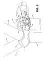
- Figure 3 is a perspective view of a wind turbine in a partial stage of disassembly.
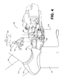
- Figure 4 is a perspective view of the wind turbine of Figure 1 showing the removal of some of the components therein and the insertion of a shaft-restraining member as practiced in some configurations of the present invention.
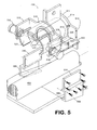
- Figure 5 is an exploded view of a portion of the wind turbine of Figure 4, showing mounting details of the shaft-restraining member shown in Figure 4 and additional shaft-restraining members.
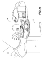
- Figure 6 is a perspective view of the wind turbine of Figure 4 showing the gearbox removed and an end of the shaft exposed.
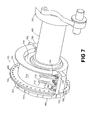
- Figure 7 is a partial perspective view of part of a shaft of a wind turbine, showing another configuration of shaft-restraining members (i.e., a rotor locks) of the present invention.
- Figure 8 is a cross-sectional perspective view of the shaft, the shaft-restraining members, and a journal or bearing of the shaft of Figure 7.
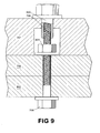
- Figure 9 is a cross-sectional view of a bolt configuration suitable for affixing a shaft-restraining member to a main bearing housing.
- More than one Figure must be referenced simultaneously to achieve a complete understanding of certain aspects of the present invention. To assist the reader, where possible, the first digit of a reference numeral for an item matches the first figure number in which the corresponding item is first described (but not necessarily the first figure in which the item appears). All further references to that item use that same reference numeral, even when describing other figures.
- In some configurations of the present invention, an object (sometimes referred to herein as a "first object") is replaced in an apparatus in an elevated location. The first object anchors a first end of an essentially horizontal rotatable shaft in the apparatus. Another object (sometimes referred to herein as a "second object") at a second, opposite end of the shaft is present and tends to destabilize the shaft from its essentially horizontal position when the first object is not present. Some configurations of the present invention provide a temporary stabilization of the horizontal shaft that permits replacement of the first object without removal of the second object during the replacement procedure. In some configurations of the present invention, the apparatus is a wind turbine, the first object is a gearbox of the wind turbine, and the replacement object is a replacement gearbox. In some configurations, a locking or clamping arrangement is provided that holds the horizontal main shaft at winds up to 25 meters per second, or over 50 miles per hour. However, in many configurations, for safety reasons, the replacement of the gearbox is limited to conditions in which winds are not more than 8 meters per second, or about 18 miles per hour. In addition, many wind turbine configurations in which gearboxes are replaced have three blades on their rotors. Some configurations of the present invention rotate the blades so that one blade is pointed straight down and the other blades are in a rabbit ear configuration. In addition, in some configurations of the present invention, the blades are pitched at an angle to avoid rotational torque on the rotor based upon the prevailing wind direction and/or the wind turbine itself is yawed for the same purpose.
- More particularly and referring to Figure 1,
flow chart 200 of Figure 2, and Figure 3, in some configurations of the present invention, agearbox 300 of awind turbine 100 is removed using asingle crane 102 that is deployed 202 to a repair site.Wind turbine 100 comprises arotor 104 having at least oneblade 106. In the most common configuration,rotor 104 has threeblades 106, but configurations of the present invention are not limited to rotor configurations having a specific number of blades.Wind turbine 100 also comprises anacelle 108 that is mounted atop atower 110. Nacelle 108 houses various mechanical and electrical components ofwind turbine 100, includinggearbox 300. Nacelle 108 comprises acowling 112, atop portion 114 of which is removed 204 at least in part by maneuveringhook 116 oncrane 102 to a handle, hook, or other protuberance or opening oftop portion 114 configured for the purpose, and liftingtop portion 114 off. In many configurations, in addition to the steps discussed herein, bolts are removed to uncap pillow blocks, and after the pillow blocks are removed, a transmission and a yaw motor are both removed. - Figure 3 is an illustration of
nacelle 108 ofwind turbine 100 with cowlingtop portion 114 removed. Other components ofwind turbine 100 that interfere with the installation of a shaft-restraining collar (to be described below) are also removed, for example,oil cooler 302, as shown schematically in Figure 4. To provide better visibility of components withinnacelle 108. thebottom portion 120 ofcowling 112 has been omitted from Figure 3. However, it is not necessary to removebottom portion 120 in many configurations of the present invention. - Referring to Figure 2 and Figure 4, a shaft-restraining member or
members 400 is then lifted 206 intoplace using crane 102 andhook 116. A hole or ahandle 404 can be provided in member ormembers 400 to facilitate lifting. In some configurations of the present invention, shaft-restraining member or members comprise a half-spool member 401 that is used to restrain rotating shaft 402 (sometimes referred to herein as "main shaft") from tilting from its horizontal position whengearbox 300 is removed fromwind turbine 100 without the removal ofrotor 104. In some configuration of the present invention and referring to Figure 5, shaft-restrainingmembers 400 include undersupport members 500 that are mounted undermain shaft 402. Half-spool member 401 and undersupport members 500 are configured in some configurations of the present invention to also inhibit rotation ofshaft 402 due to wind onrotor 104 during at least a time beforegearbox 300 is removed until after a replacementgearbox re-anchors shaft 402 in place. - Referring to Figures 2, 4, and 5, half-
spool member 401 is fastened towind turbine 100, for example, by bolting it 208 in place. For example, in some configurations of the present invention, half-spool member 401 includes mountingwings 502 on opposite sides, although only one mountingwing 502 is visible in Figure 5. Each mountingwing 502 is configured to receive abolt 504 therethrough to slidably engage undersupport members 500 until they are adjusted into position to support an underside ofmain shaft 402 andbolts 504 tightened. (In some configurations,bolts 504 are tightened onto spacers that are not shown in the Figures so thatmain shaft 402 is supported underneath by curved sections of undersupport members 500.) Also, each mountingwing 502 in some configurations is held in place using achannel clamp 506 having aU-shaped channel 508 that attaches onto a bedplate (not explicitly shown in Figure 5) ofwind turbine 100. Eachchannel clamp 506 is bolted to a respective mountingwing 502 at both ends of half-spool member 401. Anadditional stiffening plate 510 is bolted toflanges 512 protruding from spool ends 514 and 516 of half-spool member 401. - Hydraulic or mechanically operated
friction brakes 518 are provided in some configurations to clampmain shaft 402 and thereby inhibit rotation ofshaft 402. In some configurations,brakes 518 are provided on opposingbrake support flanges 519 extending in an essentially axial direction from anend 516 of half-spool member 401. For example,brakes 518 comprise opposing cylinders each supported by one of the opposingbrake support flanges 519. The hydraulic or mechanical clamping action ofbrakes 518 aroundmain shaft 402 resists torque fromrotor 104. (In some configurations, mechanical clamping action is or can be provided electromechanically.) - In some configurations, shaft-restraining
members 400 are configured to allow for rotation ofrotor 104 during high wind speed events that may occur during replacement ofgearbox 300 to prevent damage towind turbine 100 or the danger of heavy components that might shear off in such conditions. For example, surfaces 520 are Teflon(TM)-covered or provided with roller bearing surfaces in some configurations that allow rotation ofshaft 402 above a predetermined torque. - In some configurations and referring to Figure 6, one or
more yaw motors 600 are then secured 210 tomain shaft 402 to prevent rotation ofrotor 104. Ayaw motor 600 may be located on each side ofmain shaft 402.Gearbox 300 is then removed 212 by uncoupling it frommain shaft 402 and lowering it to theground using crane 102. Areplacement gearbox 300 is lifted usingcrane 102, put in place innacelle 108 and attached 214 tomain shaft 402, thereby re-anchoringfirst end 602 ofshaft 402. Shaft-restrainingmember 400, which was fastened towind turbine 100 to resist the tendency ofshaft 402 to destabilize by tilting due to the weight ofrotor 104 onsecond end 604 ofshaft 402, is then removed 216 and lowered to the ground, usingcrane 102 as necessary.Top portion 114 ofcowling 112 can then lifted up and reattached to complete the servicing ofwind turbine 100. - In some configurations of the present invention and referring to Figures 7 and 8, shaft-restraining members are somewhat differently configured. For example, shaft-restraining
members 700 in some configurations of the present invention comprise a somewhat differently configured half-spool member 701 having mounting ears orflanges 702 and asemi-annular member 704.Semi-annular member 704 is configured to mount between and fastened to anend 800 of half-spool member 701 using one ormore bolts 802 tightened through holes 804 proximate the periphery ofsemi-annular member 704 andholes 806 through a periphery ofend 800 of half-spool member 701.Semi-annular member 704 is also configured to mount onto a mountingflange 808 ofshaft 402, or in some configurations, tohub 122 of rotor 104 (see Figure 1). - More particularly, in some configurations, mounting
flange 808 ofshaft 402 comprises a trumpeted section having countersunkholes 810 that accommodate the heads of bolts (not shown in Figure 8) that fastenhub 122 toflange 808. One or more of these bolts are removed and replaced withlonger bolts 816 that are used to fastensemi-annular member 704 to mountingflange 808 on a side opposite hub 122 (not shown in Figure 8), but many bolts are not removed. These bolts do not interfere withsemi-annular member 704 because their heads are recessed into countersunk holes. In other configurations, holes are countersunk insemi-annular member 704 rather than in mountingflange 808 to allow a side ofsemi-annular member 704 to firmly contactflange 808. In either type of configuration,hub 122 andblades 106 need not be removed during the replacement ofgearbox 300. - In some configurations and referring to Figures 7 and 9, half-
spool member 701 is placed overmain shaft 402, and more particularly over journal orbearing 710. Mounting ears orflanges 702 of half-spool member 701 are configured to rest atop mountingflanges 706 of a journal or bearing 710 aroundmain shaft 402. For example, internally threadedbolts 900 are threaded onto a threaded end of existingbolts 708 that extend beyondnuts 904 that fasten mountingflanges 706 to bedplate 902 (not shown in Figure 7). In this manner, half-spool member 701 is fastened to bedplate 902 ofwind turbine 100.Slots 712 in mountingflanges 706 and in acylindrical body portion 714 of half-spool member 701 provide clearance forgusset plates 716 of journal or bearing 710 to pass through. - By fastening
semi-annular member 704 to mountingflange 806, half-spool member 701 tosemi-annular member 704, and half-spool member 701 to mountingflanges 706 or tobolts 708 therein,shaft 402 is effectively restrained from tilting and its rotation effectively inhibited.Gearbox 300 can then be safely removed and replaced. - In some configurations and referring again to Figure 8,
semi-annular member 704 also includes one or more axially extendingprotuberances 812 such as a tooth, a key, or a wedge (for simplicity hereinafter, the term "tooth" is used generically to refer to protuberance 812).Tooth 812 engages an appropriately shapedgap 814 in a circumference of mountingflange 808 to effectively inhibit rotation ofshaft 402. Some configurations provide more than onetooth 812, each engaging an appropriately shapednotch 814. Some configurations include one ormore teeth 812 in addition tobolts 812 to fastensemi-annular member 704 toflange 808. Some configurations have one ormore teeth 812 and do not usebolts 812 to fastensemi-annular member 704 toflange 808. - It will thus be appreciated that various configurations of the present invention not only allow replacement of a heavy elevated object, e.g., a gearbox in a wind turbine, with only one crane, without removing the shaft that it is on or the hub or blades of a rotor at the opposite end of the shaft from the gearbox.
- While the invention has been described in terms of various specific embodiments, those skilled in the art will recognize that the invention can be practiced with modification within the spirit and scope of the claims.
-
wind turbine 100 crane 102 rotor 104 blades 106 at least one blade 106 nacelle 108 tower 110 cowling 112 cowling top portion 114 hook 116 cowling bottom portion 120 hub 122 flow chart 200 deploy crane to repair site 202 remove cowling 204 lift prop shaft restraining collar 206 lift channel clamps into place with crane and attach with bolts 208 secure anti-rotation pin to prop shaft collar 210 uncouple gear box from prop shaft and lower to ground 212 reattach crane to new gear box, lift into place and attach to prop shaft 214 remove anti-rotation pin, remove channel clamps, remove restraining collar and lower respectively using crane 216 gearbox 300 oil cooler 302 shaft-restraining member or members 400 half-spool member 401 main or rotating shaft 402 hole or handle 404 under support members 500 mounting wings 502 bolts 504 channel clamp 506 U-shaped channel 508 stiffening plate 510 flanges 512 spool end 514 another spool end 516 brakes 518 opposing brake support flanges 519 surfaces 520 yaw motor 600 first end of shaft 602 second end of shaft 604 shaft-restraining members 700 half-spool member 701 mounting ears or flanges 702 semi-annular member 704 mounting flanges 706 mounting flanges 706 a journal or bearing 710 slots 712 cylindrical body portion 714 gusset plates 716 end of half spool member 800 bolts 802 holes 802 mounting flange 808 countersunk holes 810 tooth or protuberance 812 gap or notch 814 an appropriately shaped notch 814 longer bolts 816 internally threaded bolts 900 bedplate 902 nuts 904
Claims (10)
- A method for replacing a first object (300) in an apparatus (100) at an elevated location, wherein the first object anchors a first end (602) of an essentially horizontal shaft (402) in the apparatus and wherein a weight of a second object (104) at a second, opposite end (604) of the shaft tends to destabilize the shaft from its essentially horizontal position when the first object is not present, said method comprising:lifting (206) a shaft-restraining member or members (400) to the apparatus;fastening (208) the shaft-restraining member or members to the apparatus to thereby restrain the shaft from tilting when the first object is removed from the apparatus;removing (212) the first object from the apparatus with the shaft-restraining member or members fastened to the apparatus;re-anchoring (214) the first end of the shaft with a replacement object (300); andremoving (216) the shaft-restraining member or members from the apparatus after the shaft is re-anchored by the replacement object.
- A method in accordance with Claim 1 wherein the shaft is a rotating shaft, and said method further comprises (210) inhibiting rotation of the shaft from a time before said removal of the first object and said re-anchoring of the first of the shaft.
- A method in accordance with Claim 2 wherein said apparatus is a wind turbine (100), the first object is a gearbox (300), the second object is a rotor (104) of the wind turbine, and the replacement object is a replacement gearbox (300).
- A method in accordance with Claim 3 wherein the apparatus is a wind turbine generator (100) having a rotor (104), said lifting the restraining member to the apparatus further comprises utilizing a crane (102) to lift at least one of the restraining members (400), and said replacing the first object is performed without removing the rotor from the wind turbine generator.
- A method in accordance with any preceding Claim wherein the-shaft is a rotating shaft (402), the apparatus is a wind turbine (100), the first object is a gearbox (300), the second object is a rotor (104) of the wind turbine, the replacement object is a replacement gearbox (300), and the shaft-restraining member or members comprise a half-spool member (401), wherein said fastening the shaft-restraining member or members to the apparatus further comprises mounting half-spool member over the shaft and fastening the half-spool member to a bedplate (902) of the wind turbine.
- An apparatus (400) for stabilizing a shaft (402) in an essentially horizontal position while an anchoring object (300) at one end (602) of the shaft is replaced without removal of an object (104) at the opposite end (604) of the shaft that would otherwise tend to destabilize the shaft from its essentially horizontal position, said apparatus comprising:a half-spool member (401) configured to clamp above and around the shaft to resist torque around a rotor (104);under supports (500) configured to attach to the half-spool member and clamp an underside of the shaft below the half-spool member; anda hydraulic or mechanical brake (518) configured to resist torque on the shaft when the brake is engaged.
- An apparatus in accordance with Claim 6 wherein at least said half-spool member and said under supports comprise surfaces (520) configured to allow rotation of the shaft above a predetermined torque.
- An apparatus in accordance with Claim 6 or Claim 7 wherein said half-spool member comprises mounting wings (502), and said apparatus further comprises channel clamps (506) configured to clamp to a bed frame of the apparatus and bolt to said mounting wings.
- An apparatus in accordance with any one of Claims 6 to 8 wherein said half-spool member further comprises:mounting wings (502) on opposite sides of the half-spool member; andopposing brake support flanges (519) extending axially from ends of the half-spool member;and further wherein said brakes comprise opposing cylinders each supported by one of said opposing brake support flanges.
- An apparatus (700) for stabilizing a shaft (402) in an essentially horizontal position while an anchoring object (300) at one end (602) of the shaft is replaced without removal of an object (104) at the opposite end (604) of the shaft that would otherwise tend to destabilize the shaft from its essentially horizontal position, said apparatus comprising:a half-spool member (701) having a mounting ear or flange (702) configured to attach to a mounting flange (706) of a bearing or journal (710) of the shaft;a semi-annular member (704) configured to mount between and attach to an end of the half-spool member (800) and a flange or hub (808) of the shaft;said half-spool member and said semi-annular member configured to bolt together, and said semi-annular member configured to bolt to a flange of the shaft.
Applications Claiming Priority (1)
| Application Number | Priority Date | Filing Date | Title |
|---|---|---|---|
| US11/190,761 US7721434B2 (en) | 2005-07-27 | 2005-07-27 | Methods and apparatus for replacing objects on horizontal shafts in elevated locations |
Publications (3)
| Publication Number | Publication Date |
|---|---|
| EP1748182A2 true EP1748182A2 (en) | 2007-01-31 |
| EP1748182A3 EP1748182A3 (en) | 2012-09-12 |
| EP1748182B1 EP1748182B1 (en) | 2013-11-06 |
Family
ID=36922154
Family Applications (1)
| Application Number | Title | Priority Date | Filing Date |
|---|---|---|---|
| EP06253865.7A Not-in-force EP1748182B1 (en) | 2005-07-27 | 2006-07-24 | Method and apparatus for replacing a gearbox in a wind turbine |
Country Status (3)
| Country | Link |
|---|---|
| US (2) | US7721434B2 (en) |
| EP (1) | EP1748182B1 (en) |
| DK (1) | DK1748182T3 (en) |
Cited By (15)
| Publication number | Priority date | Publication date | Assignee | Title |
|---|---|---|---|---|
| WO2009074859A3 (en) * | 2007-12-11 | 2009-12-03 | Innovative Windpower Ag | Maintenance device for a wind turbine and mounting method |
| WO2010102967A3 (en) * | 2009-03-13 | 2011-06-23 | Vestas Wind Systems A/S | A rotor lock for a wind turbine |
| CN102220942A (en) * | 2010-04-19 | 2011-10-19 | 株式会社海星产电 | Cycloid reduction gear for wind force generator |
| CN102278290A (en) * | 2010-04-21 | 2011-12-14 | 通用电气公司 | Systems and methods for assembling a gearbox handling assembly for use in a wind turbine |
| US8108997B2 (en) * | 2005-07-27 | 2012-02-07 | General Electric Company | Methods and apparatus for replacing objects on horizontal shafts in elevated locations |
| CN102374122A (en) * | 2010-08-04 | 2012-03-14 | 通用电气公司 | Yaw assembly for use in wind turbines |
| EP2085612A3 (en) * | 2008-01-29 | 2013-01-09 | General Electric Company | Stackable nacelle for wind turbines |
| CN103056801A (en) * | 2012-12-14 | 2013-04-24 | 北车风电有限公司 | Main transmission chain completion assembly tool for fan and method thereof |
| WO2016055065A1 (en) | 2014-10-07 | 2016-04-14 | Liftra Ip Aps | Main shaft fixture |
| EP2301710A3 (en) * | 2009-09-25 | 2018-01-10 | General Electric Company | Method and system for disengaging a shrink coupling on a turbine generator |
| WO2019234179A1 (en) | 2018-06-06 | 2019-12-12 | Senvion Gmbh | Wind power plant |
| WO2021121494A1 (en) * | 2019-12-16 | 2021-06-24 | Vestas Wind Systems A/S | Tool for supporting internal rotatable members of wind turbine components during maintenance and method of using same |
| EP3869033A1 (en) * | 2020-02-20 | 2021-08-25 | Siemens Gamesa Renewable Energy Innovation & Technology, S.L. | Locking system for locking the main shaft of a wind turbine and wind turbine |
| CN113907547A (en) * | 2021-10-14 | 2022-01-11 | 国网河南省电力公司洛宁县供电公司 | Seat for power maintenance |
| EP3961032A1 (en) * | 2020-08-24 | 2022-03-02 | General Electric Company | Integrated system and method for servicing a component of a wind turbine |
Families Citing this family (35)
| Publication number | Priority date | Publication date | Assignee | Title |
|---|---|---|---|---|
| US7360310B2 (en) * | 2005-10-05 | 2008-04-22 | General Electric Company | Method for changing removable bearing for a wind turbine generator |
| WO2009100377A1 (en) | 2008-02-07 | 2009-08-13 | Wind Innovatins Ip, Llc | Rotor hub maintenance system |
| US8070446B2 (en) * | 2008-09-10 | 2011-12-06 | Moog Japan Ltd. | Wind turbine blade pitch control system |
| GB0916189D0 (en) * | 2009-09-15 | 2009-10-28 | Ricardo Uk Ltd | Bearing for wind turbine |
| EP2494196B1 (en) * | 2009-10-28 | 2019-01-09 | Vestas Wind Systems A/S | A wind power installation and methods of using a machine frame in a wind power installation |
| US8556591B2 (en) * | 2010-04-21 | 2013-10-15 | General Electric Company | Systems and methods for assembling a rotor lock assembly for use in a wind turbine |
| US20110140441A1 (en) * | 2010-08-11 | 2011-06-16 | General Electric Company | Gearbox support system |
| US20110140440A1 (en) * | 2010-08-11 | 2011-06-16 | General Electric Company | Gearbox support system |
| DE102010039628A1 (en) * | 2010-08-20 | 2012-02-23 | Ssb Service Gmbh | Rotor locking device and method for locking a rotor of a wind turbine |
| CN101947726B (en) * | 2010-10-13 | 2011-12-28 | 济南轨道交通装备有限责任公司 | Method and device for disassembling gear box of wind driven generator |
| US8726477B2 (en) | 2011-02-28 | 2014-05-20 | Pratt & Whitney Canada Corp. | Rotor centralization for turbine engine assembly |
| DK2715123T3 (en) * | 2011-05-27 | 2018-04-16 | Condor Wind Energy Ltd | WIND MILL CONTROL SYSTEM WITH A PRESSURE SENSOR |
| US8500400B2 (en) * | 2011-09-20 | 2013-08-06 | General Electric Company | Component handling system for use in wind turbines and methods of positioning a drive train component |
| KR20130059309A (en) | 2011-09-22 | 2013-06-05 | 미츠비시 쥬고교 가부시키가이샤 | Renewable energy type generating apparatus, and mounting and demounting method of a rotary blade thereof |
| US20140286788A1 (en) * | 2011-11-29 | 2014-09-25 | Daewoo Shipbuilding & Marine Engineering Co., Ltd. | Wind power generator |
| RU2504466C2 (en) * | 2012-02-21 | 2014-01-20 | Федеральное государственное бюджетное образовательное учреждение высшего профессионального образования "Пензенская государственная технологическая академия" | Method of reconditioning of shafts |
| CN102729022B (en) * | 2012-06-15 | 2015-05-06 | 国电联合动力技术(连云港)有限公司 | Device and method for assembling transmission system of large-scale wind generating set |
| US9097123B2 (en) | 2012-07-26 | 2015-08-04 | General Electric Company | Method and system for assembling and disassembling turbomachines |
| DE102012109403B3 (en) * | 2012-10-02 | 2014-03-06 | Repower Systems Se | Method for mounting a rotor blade and mounting arrangement |
| WO2016079822A1 (en) * | 2014-11-19 | 2016-05-26 | 三菱日立パワーシステムズ株式会社 | Maintenance method for gas turbine |
| US9803739B2 (en) | 2015-04-16 | 2017-10-31 | General Electric Company | Gearbox adjustment system |
| US10107255B2 (en) | 2015-04-16 | 2018-10-23 | General Electric Company | Gearbox repair apparatus |
| EP3299616B1 (en) * | 2016-09-23 | 2019-07-10 | Siemens Gamesa Renewable Energy A/S | Mounting segments and a wind turbine with mounting segments |
| CN108661864B (en) * | 2017-03-29 | 2022-03-22 | 通用电气公司 | Repair method for gearbox assembly for wind turbine |
| US10570888B2 (en) * | 2017-04-27 | 2020-02-25 | General Electric Company | Working platform within a nacelle of a wind turbine |
| US10436180B2 (en) | 2017-04-27 | 2019-10-08 | General Electric Company | Apparatus and method for removing or installing a bearing unit in a wind turbine bedplate with an adjustable bearing support |
| US10352305B2 (en) * | 2017-04-27 | 2019-07-16 | General Electric Company | System and method for removing or installing a main shaft of a wind turbine with a push/pull system configured at an end of the main shaft |
| US10337503B2 (en) | 2017-04-27 | 2019-07-02 | General Electric Company | System and method for removing or installing a main shaft of a wind turbine with rigging |
| CN107939609A (en) * | 2017-11-14 | 2018-04-20 | 山东中车风电有限公司 | A kind of three-point support structure wind power generating set wind field gear-box replacing options |
| CA3012945C (en) | 2017-11-22 | 2019-05-21 | LiftWerx Holdings Inc. | Lift system mountable in a nacelle of a wind turbine |
| CN108105041B (en) * | 2017-12-28 | 2023-05-30 | 南京高速齿轮制造有限公司 | Device for maintaining gearbox on tower and application thereof |
| CA3151491A1 (en) * | 2019-09-12 | 2021-03-18 | LiftWerx Holdings Inc. | Support system for main shaft of wind turbine |
| CN112664392B (en) | 2019-10-15 | 2025-09-05 | 通用电气可再生能源西班牙有限公司 | System and method for locking a wind turbine rotor during extended maintenance |
| WO2021222457A1 (en) * | 2020-04-28 | 2021-11-04 | Rex Peter L | Single-message electronic product and service fulfillment |
| AU2024290696A1 (en) * | 2023-07-06 | 2026-01-29 | Liftwerx Solutions Inc. | Adjustable support system for main shaft of wind turbine |
Family Cites Families (21)
| Publication number | Priority date | Publication date | Assignee | Title |
|---|---|---|---|---|
| US1556276A (en) * | 1924-10-01 | 1925-10-06 | John H Wilson | Windmill |
| US3036667A (en) * | 1959-02-09 | 1962-05-29 | Horton Mfg Co Inc | Friction brakes |
| DE7044944U (en) * | 1970-12-05 | 1971-06-16 | Zinser Textilmaschinen Gmbh | EXTERNAL SHEET BRAKE FOR SPINDLE AND TWISTED SPINDLES |
| US5267397A (en) | 1991-06-27 | 1993-12-07 | Allied-Signal Inc. | Gas turbine engine module assembly |
| CA2341398A1 (en) | 1998-09-22 | 2000-03-30 | Antonius Siebert | Device for carrying out repair and service work especially on the rotor blades of wind turbine generators |
| US6115917A (en) * | 1998-10-20 | 2000-09-12 | General Electric Company | Single position turbine rotor repair method |
| PT1057770E (en) | 1999-06-03 | 2005-11-30 | D H Blattner & Sons Inc | ASCENSIONAL ELEVATION PLATFORM IN A GUIDE AND METHOD |
| US6772570B2 (en) * | 2000-10-18 | 2004-08-10 | Edward Horne | Variable pitch connector brackets for use in attaching supporting members to bearing members in roofs |
| WO2002038953A2 (en) | 2000-11-09 | 2002-05-16 | Beaird Industries, Inc. | Wind tower with ladders and platforms |
| US6782667B2 (en) | 2000-12-05 | 2004-08-31 | Z-Tek, Llc | Tilt-up and telescopic support tower for large structures |
| US6749393B2 (en) | 2001-08-13 | 2004-06-15 | Yevgeniya Sosonkina | Wind power plant |
| US6837673B2 (en) | 2002-01-25 | 2005-01-04 | Hitachi, Ltd. | Turbine-unit disassembling method and turbine unit |
| WO2003100248A1 (en) | 2002-05-28 | 2003-12-04 | Boreas Consultants Limited | Method and crane for installing, maintaining and decommission ing wind turbines |
| WO2004092577A1 (en) | 2003-04-15 | 2004-10-28 | Vestas Wind Systems A/S | Method of servicing the outer components of a wind turbine such as the wind turbine blades and the tower with a work platform and work platform |
| US6840522B2 (en) * | 2003-05-01 | 2005-01-11 | Thomas Merrifield | Method and apparatus for repairing automobile wheel |
| ES2423430T3 (en) | 2003-09-26 | 2013-09-20 | Vestas Wind Systems A/S | Equipment to be mounted on the hub of a wind turbine and procedure to perform the maintenance of a wind turbine using such equipment |
| DK1617075T3 (en) * | 2004-07-13 | 2009-04-14 | Eickhoff Maschinenfabrik Gmbh | Method and apparatus for replacing a drive in a wind turbine |
| DE202004020317U1 (en) * | 2004-12-17 | 2005-05-12 | Nordex Energy Gmbh | Wind power system with holder for rotor shaft has gearbox whose input is coupled to rotor shaft with separate bearing and holder between bearing and gearbox that holds rotor shaft in defined position in fitted state |
| US7721434B2 (en) * | 2005-07-27 | 2010-05-25 | General Electric Company | Methods and apparatus for replacing objects on horizontal shafts in elevated locations |
| US7836595B1 (en) * | 2009-09-25 | 2010-11-23 | General Electric Company | Method and system for disengaging a shrink coupling on a turbine generator |
| US7944079B1 (en) * | 2010-04-21 | 2011-05-17 | General Electric Company | Systems and methods for assembling a gearbox handling assembly for use in a wind turbine |
-
2005
- 2005-07-27 US US11/190,761 patent/US7721434B2/en not_active Expired - Fee Related
-
2006
- 2006-07-24 EP EP06253865.7A patent/EP1748182B1/en not_active Not-in-force
- 2006-07-24 DK DK06253865.7T patent/DK1748182T3/en active
-
2010
- 2010-05-25 US US12/787,389 patent/US8108997B2/en not_active Expired - Fee Related
Cited By (34)
| Publication number | Priority date | Publication date | Assignee | Title |
|---|---|---|---|---|
| US8108997B2 (en) * | 2005-07-27 | 2012-02-07 | General Electric Company | Methods and apparatus for replacing objects on horizontal shafts in elevated locations |
| WO2009074859A3 (en) * | 2007-12-11 | 2009-12-03 | Innovative Windpower Ag | Maintenance device for a wind turbine and mounting method |
| EP2085612A3 (en) * | 2008-01-29 | 2013-01-09 | General Electric Company | Stackable nacelle for wind turbines |
| US8944766B2 (en) | 2009-03-13 | 2015-02-03 | Vestas Wind Systems A/S | Rotor lock for a wind turbine |
| WO2010102967A3 (en) * | 2009-03-13 | 2011-06-23 | Vestas Wind Systems A/S | A rotor lock for a wind turbine |
| CN102414438A (en) * | 2009-03-13 | 2012-04-11 | 维斯塔斯风力系统有限公司 | Rotor locks for wind turbines |
| EP2301710A3 (en) * | 2009-09-25 | 2018-01-10 | General Electric Company | Method and system for disengaging a shrink coupling on a turbine generator |
| CN102220942A (en) * | 2010-04-19 | 2011-10-19 | 株式会社海星产电 | Cycloid reduction gear for wind force generator |
| CN102278290A (en) * | 2010-04-21 | 2011-12-14 | 通用电气公司 | Systems and methods for assembling a gearbox handling assembly for use in a wind turbine |
| EP2381102A3 (en) * | 2010-04-21 | 2014-06-11 | General Electric Company | Systems and methods for assembling a gearbox handling assembly for use in a wind turbine |
| CN102278290B (en) * | 2010-04-21 | 2014-08-20 | 通用电气公司 | Systems and methods for assembling a gearbox handling assembly for use in a wind turbine |
| CN102374122B (en) * | 2010-08-04 | 2015-07-01 | 通用电气公司 | Yaw assembly for use in wind turbines |
| CN102374122A (en) * | 2010-08-04 | 2012-03-14 | 通用电气公司 | Yaw assembly for use in wind turbines |
| CN103056801A (en) * | 2012-12-14 | 2013-04-24 | 北车风电有限公司 | Main transmission chain completion assembly tool for fan and method thereof |
| CN103056801B (en) * | 2012-12-14 | 2015-12-02 | 北车风电有限公司 | A kind of blower fan main drive chain completion assembly tooling and method thereof |
| US20170306930A1 (en) * | 2014-10-07 | 2017-10-26 | Liftra Ip Aps | Main shaft fixture |
| CN106795866A (en) * | 2014-10-07 | 2017-05-31 | 力富特Ip公司 | Spindle Fixture |
| JP2017533378A (en) * | 2014-10-07 | 2017-11-09 | リフトラ・アイピイ・エイピイエス | Spindle fixing device |
| WO2016055065A1 (en) | 2014-10-07 | 2016-04-14 | Liftra Ip Aps | Main shaft fixture |
| EP3204639A4 (en) * | 2014-10-07 | 2018-05-16 | Liftra IP ApS | Main shaft fixture |
| US10378518B2 (en) * | 2014-10-07 | 2019-08-13 | Liftra Ip Aps | Main shaft fixture |
| CN106795866B (en) * | 2014-10-07 | 2019-12-24 | 力富特Ip公司 | Main shaft fixing device |
| EP4538530A3 (en) * | 2014-10-07 | 2025-06-25 | Liftra IP ApS | Main shaft fixture |
| EP4198301B1 (en) | 2014-10-07 | 2025-01-29 | Liftra IP ApS | Main shaft fixture |
| US12104578B2 (en) | 2014-10-07 | 2024-10-01 | Liftra Ip Aps | Main shaft fixture |
| EP4198301A1 (en) * | 2014-10-07 | 2023-06-21 | Liftra IP ApS | Main shaft fixture |
| WO2019234179A1 (en) | 2018-06-06 | 2019-12-12 | Senvion Gmbh | Wind power plant |
| CN114787508A (en) * | 2019-12-16 | 2022-07-22 | 维斯塔斯风力系统有限公司 | Tool for supporting inner rotatable component of wind turbine assembly during maintenance and method for using same |
| US12018657B2 (en) | 2019-12-16 | 2024-06-25 | Vestas Wind Systems A/S | Tool for supporting internal rotatable members of wind turbine components during maintenance and method of using same |
| WO2021121494A1 (en) * | 2019-12-16 | 2021-06-24 | Vestas Wind Systems A/S | Tool for supporting internal rotatable members of wind turbine components during maintenance and method of using same |
| EP3869033A1 (en) * | 2020-02-20 | 2021-08-25 | Siemens Gamesa Renewable Energy Innovation & Technology, S.L. | Locking system for locking the main shaft of a wind turbine and wind turbine |
| US11313356B2 (en) | 2020-08-24 | 2022-04-26 | General Electric Company | Integrated system and method for servicing a component of a wind turbine |
| EP3961032A1 (en) * | 2020-08-24 | 2022-03-02 | General Electric Company | Integrated system and method for servicing a component of a wind turbine |
| CN113907547A (en) * | 2021-10-14 | 2022-01-11 | 国网河南省电力公司洛宁县供电公司 | Seat for power maintenance |
Also Published As
| Publication number | Publication date |
|---|---|
| US20110185568A1 (en) | 2011-08-04 |
| DK1748182T3 (en) | 2014-01-13 |
| US20070025840A1 (en) | 2007-02-01 |
| EP1748182B1 (en) | 2013-11-06 |
| EP1748182A3 (en) | 2012-09-12 |
| US7721434B2 (en) | 2010-05-25 |
| US8108997B2 (en) | 2012-02-07 |
Similar Documents
| Publication | Publication Date | Title |
|---|---|---|
| EP1748182B1 (en) | Method and apparatus for replacing a gearbox in a wind turbine | |
| US9476403B2 (en) | Wind turbine blade lowering apparatus | |
| EP2590301A1 (en) | Generator assembly | |
| US8104631B2 (en) | Portable crane system for wind turbine components | |
| US8182227B2 (en) | Wind turbine blade with lightning receptor | |
| CN101798993B (en) | Method of removing internal yaw drive in wind turbine tower | |
| EP2775137B1 (en) | System and method for re-indexing a pitch bearing of a wind turbine | |
| EP2370692B1 (en) | Method for installing a wind turbine, a nacelle for a wind turbine, and method for transporting elements of a wind turbine | |
| EP1291521A1 (en) | Wind turbine nacelle with moving crane | |
| CN101518842A (en) | Method for repairing hub inclined gear | |
| EP2484902A2 (en) | Pillow block for bed plate of wind turbine | |
| CN105649885A (en) | Wind driven generator, wind driven generator set and installation method thereof | |
| CN113107756A (en) | System and method for coupling a hub of a wind turbine to a main shaft | |
| EP3719310B1 (en) | Rotor turning device for a wind turbine rotor | |
| US10641042B2 (en) | External ladder assembly for wind turbine nacelle | |
| EP4102065B1 (en) | Hub-shaft bolted-joint connection of a wind turbine | |
| US11933266B2 (en) | Method for installing rotor blades of a wind turbine | |
| US20170067437A1 (en) | Method for re-indexing a pitch bearing of a wind turbine | |
| EP4502369A1 (en) | Handling apparatus | |
| US12497952B2 (en) | Couplings and auxiliary components for wind turbines, and associated methods | |
| US20260117745A1 (en) | Method of assembling drive train for wind turbine, wind turbine and assembly kit thereof | |
| CN121701426A (en) | Methods for replacing bearings and wind turbine generators | |
| WO2010083837A2 (en) | A gripping apparatus for handling and/or servicing components of a wind turbine, and a method and a wind turbine tower therefore |
Legal Events
| Date | Code | Title | Description |
|---|---|---|---|
| PUAI | Public reference made under article 153(3) epc to a published international application that has entered the european phase |
Free format text: ORIGINAL CODE: 0009012 |
|
| AK | Designated contracting states |
Kind code of ref document: A2 Designated state(s): AT BE BG CH CY CZ DE DK EE ES FI FR GB GR HU IE IS IT LI LT LU LV MC NL PL PT RO SE SI SK TR |
|
| AX | Request for extension of the european patent |
Extension state: AL BA HR MK YU |
|
| PUAL | Search report despatched |
Free format text: ORIGINAL CODE: 0009013 |
|
| AK | Designated contracting states |
Kind code of ref document: A3 Designated state(s): AT BE BG CH CY CZ DE DK EE ES FI FR GB GR HU IE IS IT LI LT LU LV MC NL PL PT RO SE SI SK TR |
|
| AX | Request for extension of the european patent |
Extension state: AL BA HR MK RS |
|
| RIC1 | Information provided on ipc code assigned before grant |
Ipc: F03D 1/00 20060101AFI20120808BHEP |
|
| 17P | Request for examination filed |
Effective date: 20130312 |
|
| AKX | Designation fees paid |
Designated state(s): DE DK FI |
|
| GRAP | Despatch of communication of intention to grant a patent |
Free format text: ORIGINAL CODE: EPIDOSNIGR1 |
|
| INTG | Intention to grant announced |
Effective date: 20130521 |
|
| GRAS | Grant fee paid |
Free format text: ORIGINAL CODE: EPIDOSNIGR3 |
|
| GRAA | (expected) grant |
Free format text: ORIGINAL CODE: 0009210 |
|
| AK | Designated contracting states |
Kind code of ref document: B1 Designated state(s): DE DK FI |
|
| REG | Reference to a national code |
Ref country code: DE Ref legal event code: R096 Ref document number: 602006039095 Country of ref document: DE Effective date: 20140102 |
|
| REG | Reference to a national code |
Ref country code: DK Ref legal event code: T3 Effective date: 20140106 |
|
| REG | Reference to a national code |
Ref country code: DE Ref legal event code: R097 Ref document number: 602006039095 Country of ref document: DE |
|
| PLBE | No opposition filed within time limit |
Free format text: ORIGINAL CODE: 0009261 |
|
| STAA | Information on the status of an ep patent application or granted ep patent |
Free format text: STATUS: NO OPPOSITION FILED WITHIN TIME LIMIT |
|
| 26N | No opposition filed |
Effective date: 20140807 |
|
| REG | Reference to a national code |
Ref country code: DE Ref legal event code: R097 Ref document number: 602006039095 Country of ref document: DE Effective date: 20140807 |
|
| PGFP | Annual fee paid to national office [announced via postgrant information from national office to epo] |
Ref country code: FI Payment date: 20180621 Year of fee payment: 13 |
|
| PGFP | Annual fee paid to national office [announced via postgrant information from national office to epo] |
Ref country code: DE Payment date: 20180620 Year of fee payment: 13 |
|
| PGFP | Annual fee paid to national office [announced via postgrant information from national office to epo] |
Ref country code: DK Payment date: 20180625 Year of fee payment: 13 |
|
| REG | Reference to a national code |
Ref country code: DE Ref legal event code: R119 Ref document number: 602006039095 Country of ref document: DE |
|
| REG | Reference to a national code |
Ref country code: DK Ref legal event code: EBP Effective date: 20190731 |
|
| REG | Reference to a national code |
Ref country code: FI Ref legal event code: MAE |
|
| PG25 | Lapsed in a contracting state [announced via postgrant information from national office to epo] |
Ref country code: FI Free format text: LAPSE BECAUSE OF NON-PAYMENT OF DUE FEES Effective date: 20190724 Ref country code: DE Free format text: LAPSE BECAUSE OF NON-PAYMENT OF DUE FEES Effective date: 20200201 |
|
| PG25 | Lapsed in a contracting state [announced via postgrant information from national office to epo] |
Ref country code: DK Free format text: LAPSE BECAUSE OF NON-PAYMENT OF DUE FEES Effective date: 20190731 |