EP1748151B1 - Méthode et dispositif pour la transmission ou réception d'information entre un dispositif de fond et la surface - Google Patents
Méthode et dispositif pour la transmission ou réception d'information entre un dispositif de fond et la surface Download PDFInfo
- Publication number
- EP1748151B1 EP1748151B1 EP05291628A EP05291628A EP1748151B1 EP 1748151 B1 EP1748151 B1 EP 1748151B1 EP 05291628 A EP05291628 A EP 05291628A EP 05291628 A EP05291628 A EP 05291628A EP 1748151 B1 EP1748151 B1 EP 1748151B1
- Authority
- EP
- European Patent Office
- Prior art keywords
- electrodes
- well
- transducer
- location
- electrode
- Prior art date
- Legal status (The legal status is an assumption and is not a legal conclusion. Google has not performed a legal analysis and makes no representation as to the accuracy of the status listed.)
- Not-in-force
Links
- 238000000034 method Methods 0.000 title claims abstract description 54
- 230000015572 biosynthetic process Effects 0.000 claims abstract description 64
- 238000011144 upstream manufacturing Methods 0.000 claims abstract description 36
- 238000005259 measurement Methods 0.000 claims description 34
- 229910003460 diamond Inorganic materials 0.000 claims description 19
- 239000010432 diamond Substances 0.000 claims description 19
- 238000012544 monitoring process Methods 0.000 claims description 12
- 239000002131 composite material Substances 0.000 claims description 8
- 230000001419 dependent effect Effects 0.000 claims description 7
- 230000005291 magnetic effect Effects 0.000 abstract description 29
- 238000004891 communication Methods 0.000 description 31
- 239000012530 fluid Substances 0.000 description 24
- 230000005540 biological transmission Effects 0.000 description 16
- 229910052751 metal Inorganic materials 0.000 description 11
- 230000005684 electric field Effects 0.000 description 10
- 230000006870 function Effects 0.000 description 10
- 239000002184 metal Substances 0.000 description 10
- 238000010586 diagram Methods 0.000 description 9
- 229910017052 cobalt Inorganic materials 0.000 description 8
- 239000010941 cobalt Substances 0.000 description 8
- GUTLYIVDDKVIGB-UHFFFAOYSA-N cobalt atom Chemical compound [Co] GUTLYIVDDKVIGB-UHFFFAOYSA-N 0.000 description 8
- 239000003973 paint Substances 0.000 description 8
- 238000001228 spectrum Methods 0.000 description 8
- 241000238366 Cephalopoda Species 0.000 description 5
- 238000010606 normalization Methods 0.000 description 5
- 230000037361 pathway Effects 0.000 description 5
- 230000001681 protective effect Effects 0.000 description 5
- 230000035945 sensitivity Effects 0.000 description 5
- UONOETXJSWQNOL-UHFFFAOYSA-N tungsten carbide Chemical compound [W+]#[C-] UONOETXJSWQNOL-UHFFFAOYSA-N 0.000 description 5
- 230000004913 activation Effects 0.000 description 4
- 230000008901 benefit Effects 0.000 description 4
- 239000004020 conductor Substances 0.000 description 4
- PCHJSUWPFVWCPO-UHFFFAOYSA-N gold Chemical compound [Au] PCHJSUWPFVWCPO-UHFFFAOYSA-N 0.000 description 4
- 239000010931 gold Substances 0.000 description 4
- 229910052737 gold Inorganic materials 0.000 description 4
- 239000012212 insulator Substances 0.000 description 4
- XLYOFNOQVPJJNP-UHFFFAOYSA-N water Substances O XLYOFNOQVPJJNP-UHFFFAOYSA-N 0.000 description 4
- 239000004593 Epoxy Substances 0.000 description 3
- 229910000831 Steel Inorganic materials 0.000 description 3
- 230000006698 induction Effects 0.000 description 3
- 238000009413 insulation Methods 0.000 description 3
- 239000000843 powder Substances 0.000 description 3
- 239000010959 steel Substances 0.000 description 3
- 239000000126 substance Substances 0.000 description 3
- 239000004696 Poly ether ether ketone Substances 0.000 description 2
- 238000005452 bending Methods 0.000 description 2
- 239000011248 coating agent Substances 0.000 description 2
- 238000000576 coating method Methods 0.000 description 2
- 238000013461 design Methods 0.000 description 2
- 238000005553 drilling Methods 0.000 description 2
- 238000009434 installation Methods 0.000 description 2
- 238000004519 manufacturing process Methods 0.000 description 2
- 238000005240 physical vapour deposition Methods 0.000 description 2
- 229920002530 polyetherether ketone Polymers 0.000 description 2
- 238000012545 processing Methods 0.000 description 2
- 239000011435 rock Substances 0.000 description 2
- 230000035939 shock Effects 0.000 description 2
- 238000003860 storage Methods 0.000 description 2
- 238000012360 testing method Methods 0.000 description 2
- RYGMFSIKBFXOCR-UHFFFAOYSA-N Copper Chemical compound [Cu] RYGMFSIKBFXOCR-UHFFFAOYSA-N 0.000 description 1
- ZOKXTWBITQBERF-UHFFFAOYSA-N Molybdenum Chemical compound [Mo] ZOKXTWBITQBERF-UHFFFAOYSA-N 0.000 description 1
- QCWXUUIWCKQGHC-UHFFFAOYSA-N Zirconium Chemical compound [Zr] QCWXUUIWCKQGHC-UHFFFAOYSA-N 0.000 description 1
- 238000000429 assembly Methods 0.000 description 1
- 230000000712 assembly Effects 0.000 description 1
- 230000002238 attenuated effect Effects 0.000 description 1
- 238000009530 blood pressure measurement Methods 0.000 description 1
- 238000009529 body temperature measurement Methods 0.000 description 1
- 238000005219 brazing Methods 0.000 description 1
- 229910052799 carbon Inorganic materials 0.000 description 1
- 239000004568 cement Substances 0.000 description 1
- 230000008859 change Effects 0.000 description 1
- 238000012790 confirmation Methods 0.000 description 1
- 230000007797 corrosion Effects 0.000 description 1
- 238000005260 corrosion Methods 0.000 description 1
- 239000013078 crystal Substances 0.000 description 1
- 230000004069 differentiation Effects 0.000 description 1
- 239000006185 dispersion Substances 0.000 description 1
- 238000009826 distribution Methods 0.000 description 1
- 230000002500 effect on skin Effects 0.000 description 1
- 230000000694 effects Effects 0.000 description 1
- 230000005520 electrodynamics Effects 0.000 description 1
- 238000005516 engineering process Methods 0.000 description 1
- 230000007613 environmental effect Effects 0.000 description 1
- 230000005294 ferromagnetic effect Effects 0.000 description 1
- 239000011810 insulating material Substances 0.000 description 1
- JEIPFZHSYJVQDO-UHFFFAOYSA-N iron(III) oxide Inorganic materials O=[Fe]O[Fe]=O JEIPFZHSYJVQDO-UHFFFAOYSA-N 0.000 description 1
- 239000007788 liquid Substances 0.000 description 1
- 239000000463 material Substances 0.000 description 1
- 230000007246 mechanism Effects 0.000 description 1
- 239000000203 mixture Substances 0.000 description 1
- 229910052750 molybdenum Inorganic materials 0.000 description 1
- 239000011733 molybdenum Substances 0.000 description 1
- 235000019476 oil-water mixture Nutrition 0.000 description 1
- 230000035699 permeability Effects 0.000 description 1
- 238000003825 pressing Methods 0.000 description 1
- 230000008569 process Effects 0.000 description 1
- 230000009467 reduction Effects 0.000 description 1
- 239000003870 refractory metal Substances 0.000 description 1
- 230000004044 response Effects 0.000 description 1
- 150000003839 salts Chemical class 0.000 description 1
- 238000000926 separation method Methods 0.000 description 1
- 239000007787 solid Substances 0.000 description 1
- 239000002887 superconductor Substances 0.000 description 1
- 238000012546 transfer Methods 0.000 description 1
- 230000001052 transient effect Effects 0.000 description 1
- WFKWXMTUELFFGS-UHFFFAOYSA-N tungsten Chemical compound [W] WFKWXMTUELFFGS-UHFFFAOYSA-N 0.000 description 1
- 229910052721 tungsten Inorganic materials 0.000 description 1
- 239000010937 tungsten Substances 0.000 description 1
- 239000002699 waste material Substances 0.000 description 1
- 239000003643 water by type Substances 0.000 description 1
- 229910052726 zirconium Inorganic materials 0.000 description 1
Images


Classifications
-
- E—FIXED CONSTRUCTIONS
- E21—EARTH DRILLING; MINING
- E21B—EARTH DRILLING, e.g. DEEP DRILLING; OBTAINING OIL, GAS, WATER, SOLUBLE OR MELTABLE MATERIALS OR A SLURRY OF MINERALS FROM WELLS
- E21B47/00—Survey of boreholes or wells
- E21B47/12—Means for transmitting measuring-signals or control signals from the well to the surface, or from the surface to the well, e.g. for logging while drilling
- E21B47/13—Means for transmitting measuring-signals or control signals from the well to the surface, or from the surface to the well, e.g. for logging while drilling by electromagnetic energy, e.g. radio frequency
-
- G—PHYSICS
- G01—MEASURING; TESTING
- G01V—GEOPHYSICS; GRAVITATIONAL MEASUREMENTS; DETECTING MASSES OR OBJECTS; TAGS
- G01V11/00—Prospecting or detecting by methods combining techniques covered by two or more of main groups G01V1/00 - G01V9/00
- G01V11/002—Details, e.g. power supply systems for logging instruments, transmitting or recording data, specially adapted for well logging, also if the prospecting method is irrelevant
- G01V11/005—Devices for positioning logging sondes with respect to the borehole wall
-
- G—PHYSICS
- G01—MEASURING; TESTING
- G01V—GEOPHYSICS; GRAVITATIONAL MEASUREMENTS; DETECTING MASSES OR OBJECTS; TAGS
- G01V3/00—Electric or magnetic prospecting or detecting; Measuring magnetic field characteristics of the earth, e.g. declination, deviation
- G01V3/08—Electric or magnetic prospecting or detecting; Measuring magnetic field characteristics of the earth, e.g. declination, deviation operating with magnetic or electric fields produced or modified by objects or geological structures or by detecting devices
- G01V3/083—Controlled source electromagnetic [CSEM] surveying
Definitions
- the present invention broadly relates to wireless telemetry. More particularly the invention relates to an apparatus and related method for transmitting or receiving information between a downhole equipment connected to an underground tubing or casing and a surface device.
- Oil and gas wells are expensive to construct, and it is advantageous to operate these wells as efficiently as possible.
- One way of providing for an increased efficiency in the operation of wells is to place equipment downhole in the well bore under the control of other equipment located on the surface.
- the equipment can be measurement sensors which supply useful information for the subsequent working of the well, for example data regarding pressure, the nature of the solids and fluids encountered, the temperature, etc.
- the equipment can be other controllable or monitoring equipments which supply important orders from the surface to control various parameters of the well or the reservoir with equipment and device such as valves, protective covers, etc. It is therefore important to be able to transmit information from the surface to various downhole equipments.
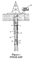
- Several prior art methods have attempted to provide electrically or electromagnetically communications between the surface equipment and the downhole equipment.
- the transmission means comprise at least an electrode that is secured to the insulating layer of the drill string, whereby the electrode is in electrical contact with the mud inside the drill string.
- a second electrical unit at the top end of the drill string is adapted to receive the information transmitted by the electrical current.
- Document US 2003/0102980 discloses a system including signal repeaters for detecting a transient disturbance in the surface charge on a drill pipe. The system is used to transmit data from deep-well and formation environments to a point near the surface. The signal repeater is thereby mounted on the interior of the drill pipe.
- Document US 2001/0033164 describes a system for measuring a formation resistivity using induction chokes to form electrically isolated piping structure sections that are used as formation contact electrodes for time-varying current.
- Document US 2003/0151977 discloses a method for transmitting information from downhole using more than one communication channel, including an electromagnetic telemetry channel, whereby a measurement-while-drilling tool may include an electromagnetic telemetry device, the tool being part of the drill string.
- a measurement-while-drilling tool may include an electromagnetic telemetry device, the tool being part of the drill string.
- the required sufficient impedance largely depends on the geometric characteristics of the well and on the impedance of the surrounding environment: filling fluid, metal tubing, casing, formation, etc. It is better to limit or control the dependency of those parameters.
- the invention provides a method of receiving and/or transmitting information in a well drilled in a geological formation between a first location and a second location, said well comprising a casing communicating with the geological formation, the method comprising: (i) placing a first transducer located at said first location, said first transducer comprising two electrodes, which are first and second downstream electrodes, said first and second downstream electrodes being in electrical contact with the casing; (ii) placing a second transducer located at said second location, said second transducer comprising two electrodes, which are first and second upstream electrodes; (iii) transmitting an electric signal with the first transducer by applying said signal between the first and second downstream electrodes or respectively with the second transducer by applying said signal between the first and second upstream electrodes; (iv) receiving said electric signal with the second transducer by detecting said signal between the first and second upstream electrodes or respectively with the first transducer by detecting said signal between the first and second downstream electrodes.
- the well further comprises a third transducer, said third transducer located at a third location and comprising two electrodes, which are first and second well electrodes, said first and second well electrodes being in electrical contact with the casing; and the method comprising the step of : (i) transmitting a second electric signal with the third transducer by applying said second signal between the first and second well electrodes; and (ii) receiving a third electric signal with the third transducer by detecting said third signal between the first and second well electrodes.
- the well can further comprise a plurality of additional transducers; every transducer can receive and/or transmit information to anyone of the transducers. A network of transducers is so defined.
- the well further comprises a relay transducer, said relay transducer located at a third location and comprising two electrodes, which are first and second well electrodes, said first and second well electrodes being in electrical contact with the casing; and the method further comprising the step of: (i) receiving the electric signal with the third transducer by detecting said signal between the first and second well electrodes; and (ii) transmitting the electric signal with the third transducer by applying said signal between the first and second well electrodes.
- the well can further comprising a plurality of additional relay transducers.
- the method can apply when the first location is in the well and the second location is at the surface of the geological formation or when the first and second locations are in the well and/or when the third location is in the well.
- the well comprises a tubing and at least one of the electrodes taken in the list: first downstream electrode, second downstream electrode, first upstream electrode, second upstream electrode, first well electrode, second well electrode, electrodes from the other transducers, is insulated electrically from the tubing, preferably also, is further insulated electrically from other conductive elements in the well and preferably also, is further shielded electromagnetically.
- the insulation allows controlling the injected current between electrodes independently of the potential of the tubing or of the other conductive elements.
- the shielding avoids and protects against electrical interferences coming from the well.
- the first distance d 1 between the first and the second downstream electrodes is dependent of intensity of the electric signal and of the distance between the first and second downstream electrodes and the first and second upstream electrodes; and/or the first distance d 1 between the first and the second downstream electrodes is dependent of intensity of the electric signal and of the distance between the first and second downstream electrodes and the first and second well electrodes; and/or the third distance d 3 between the first and the second well electrodes is dependent of the electric signal and of the distance between the first and second well electrodes and the first and second upstream electrodes.
- the dependency principally reflects the fact that electrical signal intensity from one point to the other will be dependent of the traveled distance, of the distance between electrodes and of physical characteristics of the formation.
- the first and second upstream electrodes are in electrical contact with the formation at the surface.
- the first upstream electrode is in electrical contact with the tubing and the second upstream electrode is in electrical contact with the formation at the surface.
- the first transducer, second transducer and/or third transducer can be connected to a measurement sensor and/or a control/monitoring equipment; also the electric signal communicated by the transducers contained information from the measurement sensor and/or to the control/monitoring equipment.
- an apparatus for receiving and/or transmitting information in a well drilled in a geological formation between a first location and a second location comprising a casing communicating with the geological formation, and the apparatus comprising: (i) a first transducer located at said first location, said first transducer comprising two electrodes, which are first and second downstream electrodes, said first and second downstream electrodes being in electrical contact with the casing; and (ii) a second transducer located at said second location, said second transducer comprising two electrodes, which are first and second upstream electrodes.
- the apparatus further comprises at least another third transducer, said third transducer located at a third location and comprising two electrodes, which are first and second well electrodes, said first and second well electrodes being in electrical contact with the casing.
- the third transducer can be a relay transducer. The advantages of using relays are to increase the range of the communication and/or to communicate with various locations in the well.
- the apparatus can be positioned with the first location in the well and the second location at the surface of the geological formation or with first and second locations in the well and/or with the third location in the well.
- the well comprises a tubing and at least one of the electrodes taken in the list: first downstream electrode, second downstream electrode, first upstream electrode, second upstream electrode, first well electrode and second well electrode, is insulated electrically from the tubing, preferably also, is further insulated electrically from other conductive elements in the well and preferably also, is further shielded electromagnetically.
- the insulation allows controlling the injected current between electrodes independently of the potential of the tubing or of the other conductive elements.
- the shielding avoids and protects against electrical interferences coming from the well.
- the first and second upstream electrodes are in electrical contact with the formation at the surface.
- the first upstream electrode is in electrical contact with the tubing and the second upstream electrode is in electrical contact with the formation at the surface.
- the first and/or the second downstream and/or well electrode can be any chosen in the list: a composite material which is constituted by a fine layer of polycrystalline diamond compact (PDC), a metallic bow spring, and a metallic caliper.
- PDC polycrystalline diamond compact
- the electrodes can be located on one or several packers.
- Various embodiments are possible:
- the deployment of one packer or several is controlled by the voltage difference between first and second downstream electrodes and/or first and second well electrodes.
- the electrodes can be protected by a seal or paint cover, the voltage difference being small between the two electrodes, corresponding to a high impedance between both electrodes.
- the seal or paint cover is used when annular fluids are highly conductive, when annular fluids are practically non-conductive the seal is optional, because the voltage difference will be always small.
- the deployment pressure will puncture the seal or the insulating paint and force-push the electrodes into the metal of the casing. This way, an electric contact between the electrodes and the conductive casing is established. The current between the electrodes increases accordingly, thus indicating the successful deployment of the packer.
- the first transducer, second transducer, well and/or relay transducer can be connected to a measurement sensor and/or a control/monitoring equipment.
- a method to determine the conductivity profile of a formation from a well between a first location at a surface and a second location in a borehole comprising: (i) placing a first sensor located at said first location, said first sensor detecting electric and/or magnetic field occurring at said first location from the formation; (ii) placing a second sensor located at said second location, said second sensor detecting electric and/or magnetic field occurring at said second location from the formation; (iii) obtaining a first signal by detecting Schumann resonances from said electric and/or magnetic field occurring at said first location with said first sensor; (iv) obtaining a second signal by detecting Schumann resonances from said electric and/or magnetic field occurring at said second location with said second sensor; and (v) combining said first and said second signal to determine the conductivity profile of the formation between said first location and said second location.
- the first signal is a calibration signal and the combining step is a step of comparison of the first signal and the second signal.
- the method can further comprises the step of changing the second location within the borehole and obtaining adequate signals by detecting Schumann resonances and combining those adequate signals to determine the conductivity profile of the formation between the borehole and the surface. For the first signal, second signal and adequate signals, at least two different Schumann resonance frequencies can be obtained and computed.
- the method further comprises a third location in the borehole and the steps of: placing a third sensor located at said third location, said third sensor detecting electric and/or magnetic field occurring at said third location from the formation; obtaining a third signal by detecting Schumann resonances from said electric and/or magnetic field occurring at said third location with said third sensor; combining said first and said third signal to determine the conductivity profile of the formation between said first location and said third location; and combining said second and said third signal to determine the conductivity profile of the formation between the borehole and the surface.
- the first signal is a calibration signal and the combining step is a step of comparison of the first signal and the third signal.
- the first signal, second signal and third signal at least two different Schumann resonance frequencies can be obtained and computed.
- the method to determine the conductivity profile using Schumann resonances is realized with an apparatus as described above.
- an apparatus to determine the conductivity profile of a formation from a well between a first location at a surface and a second location in a borehole comprising: (i) a first sensor located at said first location, said first sensor detecting electric and/or magnetic field occurring at said first location from the formation; and simultaneously (ii) a second sensor located at said second location, said second sensor detecting electric and/or magnetic field occurring at said second location from the formation.
- the first and/or second sensor has sensibility and resolution to detect Schumann resonances from said electric and/or magnetic field occurring at said first location, respectively and/or at said second location.
- the apparatus is lowered in the borehole from the surface.
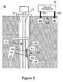
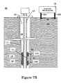
- FIG. 2 is an illustration of the apparatus according to the present invention in a first embodiment.
- a first transducer 14, the well transducer is installed in a well 10, the well comprising a tubing 13 and a casing 11 surrounding formation 12.
- An annular 18 is formed between the casing and the tubing, which is filled with an annular fluid.
- the casing and the tubing are conductive, normally made of steel.
- the well transducer has an upper electrode 141 which ensures contact with the casing at a pole E1 and an upon electrode 142 which also ensures contact with the casing at a pole E2.
- the upper electrode 141 and/or the upon electrode 142 are/is insulated electrically from the tubing 13 with an insulator 16.
- the upper electrode 141 and/or the upon electrode 142 are/is insulated against other conductive elements in the well, such as highly conductive annular fluids.
- the insulation allows controlling the injected current between the electrodes 141 and 142 independently of the potential of the tubing or of the annular fluid or even of other conductive elements.
- the upper electrode 141 and/or the upon electrode 142 have/has a shielding.
- An insulated metallic element surrounding the electrodes can be this shielding. The shielding avoids and protects against electrical interferences coming from the well, more precisely from the inside of the casing such as the annular fluid or from the tubing.
- the design of the electrodes 141 and 142 will be explained in more details hereinafter.
- the effectiveness of the apparatus is proportional to the distance d 1 between E1 and E2.
- the poles E1 and E2 with the characterized distance d 1 will define the well dipole D1.
- the dipole D1 can extend over a considerable distance of the casing going from 10 feet (3 meters) to 3000 feet (1000 meters), preferably chosen in the range from 30 feet (10 meters) to 300 feet (100 meters).
- the casing can be coated with an electrically insulating deposit such as epoxy. This coating will significantly reduce the electrical losses into conductive annular fluids.
- a second transducer 15, the surface transducer, is installed at the surface 20.
- the surface transducer has a first electrode 151 which ensures contact with the formation at a pole E3 and a second electrode 152 which also ensures contact with the formation at a pole E4.
- the design of the electrodes 151 and 152 will be explained in more details hereinafter.
- the effectiveness of the apparatus is also proportional to the distance d 2 between E3 and E4.
- the poles E3 and E4 with the characterized distance d 2 will define the surface dipole D2.
- the dipole D2 can extend over a considerable distance of the formation going from 10 feet (3 meters) to 3000 feet (1000 meters), preferably chosen in the range from 150 feet (50 meters) to 600 feet (200 meters).
- the well transducer 14 can be constituted of a protective housing comprising an electronics package and two insulated cables connected respectively to the electrodes 141 and 142.
- the electronics package ensures function of the transducer, and comprises, as for example, a signal processing unit and a power supply unit.
- the processing unit can further comprise a transmission and reception communication unit, a programmable micro-controller and a memory unit.
- the protective housing of the well transducer can be located on the inner or outer surface of the tubing or even on the inner or outer surface of the casing.
- the insulated cables connect the protective housing to the upper and upon electrodes.
- the electronics package can be connected to measurement sensors (not shown).
- the sensor can be mounted on the outer or inner surface of the casing or tubing.
- Sensors can measure properties from the formation or alternatively properties from the well infrastructure as casing or tubing, or even alternatively properties from fluid inside the well; combination of several sensors measuring various properties is also possible.
- Such sensors can, for example, measure the fluid pressure or velocity inside the well or measure the surrounding formation fluid pressure, resistivity, salinity or detect the presence of chemical components such as CO 2 or H 2 S, the sensors can also be applied to measure casing or tubing properties such as corrosion, strain and stress.
- the following types of sensors can be implemented:
- Multi-sensors can also be used, for example two sensors to measure both electric and magnetic fields at very high sensitivity.
- the considerable benefit of using both E and B sensors is not just to collect their individual outputs separately, but rather to combine their outputs to provide an integrated, processed electromagnetic system output.
- the electric and magnetic field data can be synthesized to reduce the amount of noise or interferences by combining channel data, while yielding improved fidelity by exploiting specific physical relationships between E and B data for specific targets and environmental conditions.
- Other type of multi-sensor can also be used, by combining both electric and magnetic fields and temperature or pressure measurements.
- the electronics package can also be connected to control or monitoring equipments (not shown).
- the equipments can be passive or active control equipments, one can be activated directly from the surface through the communication apparatus according to the present invention, additionally the equipment can confirm its activation also through the communication apparatus to the surface; and the other one can be auto-activated downhole when predefined well properties are reached, the equipment confirms so its activation through the communication apparatus to the surface.
- Such equipments can be for example: controllable valve, protective cover and expandable packer.
- Apparatus according to the invention can be used to monitor formation or monitor/control well properties in various domains, such as:
- the electrodes 141 and 142 can be any one of the electrodes here below presented either with the same electrodes or with different electrodes.
- FIG. 6 shows an embodiment or the electrode 141 or 142 as a point-contact electrode 41.
- the electrode 41 is included in an insulating sleeve 52, e.g. made of polyether ether ketone (PEEK).
- PEEK polyether ether ketone
- the base of the electrode is securely bonded, e.g. by brazing, to a support 53 that co-operates with a spring 50.
- the spring 50 serves to press the electrode continuously against the measurement surface.
- the assembly comprising the electrode 41, the insulating sleeve 52, and the support 53 is itself carried by a pad 54.
- the electrode is beveled in shape. This embodiment is particularly advantageous when an electrode is used to ensure electrical contact with the inner surface of the metal casing.
- the metal casing becomes covered very quickly in a layer of rust which must be penetrated in order to ensure that the contact between the electrode and the casing is correct.
- the beveled shape is sufficiently sharp to pierce said layer.
- the electrode is made of a composite material which is constituted by a fine layer of polycrystalline diamond compact (PDC) bonded to an amalgamated tungsten carbide support, enriched with about 7% cobalt.
- PDC polycrystalline diamond compact
- such an assembly is made by placing diamond powder (advantageously of the finest grain size) in a refractory metal mold generally of zirconium or of molybdenum. The shape of the mold determines the shape of the composite. Thereafter, a tungsten carbide support is placed over the diamond powder and the mold is sealed hermetically. The assembly is then placed in a press at a temperature of about 1400°C and at a pressure of about 69,000 bars (1 MPsi), for a length of time that is too short to affect the diamond.
- the presence of cobalt in the diamond makes the diamond electrically conductive.
- the electrode makes it possible to combine electrical properties with the excellent mechanical properties of diamond.
- tungsten could be associated with some other element in order to make the diamond electrically conductive. It is also possible to replace the tungsten carbide with some other support material, providing it presents the same compatibility with diamond powder and cobalt or some other element for making diamond conductive.
- the PDC electrode is covered in a layer of gold, e.g. deposited by physical vapor deposition (PVD) and having a thickness that is typically of the order of a few micrometers. It has been shown that the covering of gold adheres strongly and durably to the PDC. The layer of gold thus makes it possible significantly to increase the conductivity of the electrodes.
- PDC thus combines the excellent mechanical properties of diamond, in particular its hardness and its resistance both to shock and also to temperature (it remains chemically stable up to about 720°C), with electrical properties due to cobalt doping, possibly assisted by a deposit of gold. This makes the electrodes particularly good at withstanding shock, temperature, and also corrosive media.
- the electrode 141 or 142 in another embodiment can be a metallic spring bow in close contact with the inner surface of the casing with enough force to ensure electrical contact.
- the electrode 141 or 142 in another embodiment can be a metallic caliper in close contact with the inner surface of the casing with enough force to ensure electrical contact.
- the electrode 141 or 142 in another embodiment can be a metallic point with pressing means to ensure electrical contact with the inner surface of the casing.
- the electrodes 151 and 152 can be any one of the electrodes here below presented either with the same electrodes or with different electrodes.
- the electrode 151 or 152 can be a metallic bar hammered on the surface in the formation.
- the electrode 151 or 152 can be a metallic cable going into the formation from the surface within some meters.
- Figure 3 illustrates a variation of the apparatus of Figure 2 .
- the upper electrode 141 and the upon electrode 142 are not interdependent.
- the upper electrode 141 ensures contact with the casing at a pole E1 and the upon electrode 142 ensures contact with the casing at a pole E2.
- the upper electrode 141 is insulated electrically from the tubing 13 with an insulator 16.
- the upon electrode 142 is insulated electrically from the tubing 13 with an insulator 16'.
- the transducer 14 is connected to the electrode 141 through a conductor cable 143 and to the electrode 142 through a conductor cable 144.
- the cables 143 and 144 are coated with an insulated jacket to avoid any current leakage through the tubing or the annular fluid.
- the effectiveness of the apparatus is proportional to the distance d 1 between E1 and E2.
- the poles E1 and E2 with the characterized distance d 1 will define the well dipole D1.
- the dipole D1 can extend over a considerable distance of the casing going from 10 feet (3 meters) to 3000 feet (1000 meters), preferably chosen in the range from 30 feet (10 meters) to 300 feet (100 meters).
- the casing can be coated with an electrically insulating deposit such as epoxy. This coating will significantly reduce the electrical losses into conductive annular fluids.
- intermediate and insulating centralizers might have to be added along the tubing to avoid electrical contact with the casing due to tubing flexion or bending. Such electrical contacts would alter the communication. Rubber types insulating centralizers can be used. Also, the tubing can be coated with an electrically insulating deposit such as epoxy to avoid electrical contact with the casing due to tubing flexion or bending.
- Figure 4 illustrates another variation of the apparatus of Figure 2 .
- the second transducer 15, the surface transducer is installed at the surface 20. But this time, the surface transducer has a first electrode 151 which ensures contact with the tubing at a pole E3 and a second electrode 152 which ensures contact with the formation at a pole E4.
- Other embodiments of Figures 2 , 3 and 4 can be implemented without changing the scope of the invention.
- Figure 5A and 5B illustrate the apparatus according to Figure 2 , in a configuration of horizontal well.
- the surface transducer is in mode transmitter and the well transducer is in mode receiver.
- the surface transducer is in mode receiver and the well transducer is in mode transmitter.
- the transmission and reception mode are presented in configuration of horizontal well, but can also be performed in configuration of vertical well or any inclination of the well.
- a casing axis 13' defines the horizontal axis and also x axis, perpendicular to the casing axis, the vertical axis defines the z axis, the y axis is defined such that ( x, y, z ) is a direct orthogonal trihedron.
- a realistic example illustrates the surface-to-downhole telemetry and provides an estimate for the expected signal strength.
- the two electrodes 151 and 152 are placed into the ground and along the horizontal-well trajectory. The two electrodes are 100m apart, so that the downhole telemetry station is in the middle.
- the factor 2 in front of the square bracket accounts for the insulating air half-space above the earth surface.
- the amount of current is sufficient to be detected by ordinary electronics in the electronics package.
- the voltage created by the receiver can be continuous signal, if an information of activation has to be transmitted (close for signal and open for no signal, for example) or alternative signal with characterized frequency, if more complex data need to be transmitted.
- the characterized frequency can be few Hertz, 1 to 10 Hz typically.
- the point-contact electrodes 141 and 142 are equally used as transmitter.
- the electronics package must drive a large source current (preferably between 1 and 10A or more than 10A) through almost a short circuit.
- the current created by the receiver can be continuous signal, if information of confirmation of activation has to be transmitted or alternative signal with characterized frequency, if more complex data need to be transmitted.
- the characterized frequency can be few Hertz, 1 to 10 Hz typically.
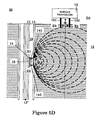
- Figure 5C and 5D illustrate the apparatus according to Figure 2 , in a configuration of vertical well.
- the surface transducer is in mode transmitter and the well transducer is in mode receiver.
- the surface transducer is in mode receiver and the well transducer is in mode transmitter.
- the transmission and reception mode in configuration of vertical well works in the same way as described above.
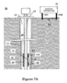
- Figure 7A and 7B illustrate one embodiment of the apparatus according to Figure 2 when using a long packer 20.
- Figure 8A and 8B illustrate one embodiment of the apparatus according to Figure 3 when using a pair of short packer 20' and 20".
- the long packer 20 is installed in deflated state around the tubing 13.
- point-contact electrodes 141 and 142 are mounted and wired to a suitable electronics package containing the transducer 14.
- the electronics package can be mounted anyway in the well or even on the packer 20.
- the wired connections are insulated with a jacket to avoid any current leakage through the tubing or the annular fluid.
- the point-contact electrodes may initially be covered by a puncture seal or insulating paint. This seal or paint will later be destroyed during deployment.
- the tubing equipped with the electrodes-packer 20 is lowered into a steel-cased well to its predetermined depth. Hence the packer is inflated to provide a hydraulically tight seal between the tubing outer wall and the casing inner wall.
- the point-contact electrodes 141 and 142 are set at a small voltage, and the current through the electrodes is monitored.
- the electronics package contains the required battery for voltage support and an ohmmeter, for example as monitoring system of the return current. As the electrodes are still protected by their seal or paint cover the current is small, corresponding to a high impedance between the electrodes 141 and 142.
- the transducer 14 can be activated to begin the reception or transmission mode accordingly to Figure 5A or 5B .
- a pair of short packer 20' and 20" are installed in deflated state around the tubing 13.
- point-contact electrodes 141 and 142 are mounted and wired to a suitable electronics package containing the transducer 14.
- the electronics package can be mounted anyway in the well.
- the wired connections are insulated with a jacket to avoid any current leakage through the tubing or the annular fluid. The other characteristics are similar to the long packer 20.
- the long packer 20 or the both short packers 20' and 20" can be instrumented packers, which mean that the packers can contain measurement sensors such instrumented packers are disclosed in patent application US2003094282 .
- the measurement sensor is located on the packer surface or in the packer. The measurement sensor can be deployed when packer is deflated or can be deployed when packer is inflated.
- an apparatus containing a transducer and two electrodes contacting a casing is represented by a dipole Di with i varying between 1 and 6.
- the dipole Di can be a transmission dipole, a reception dipole or both reception/transmission dipole.
- Each dipole is located in the well at defined location.
- D1, D2 and D3 are located in a first well
- D4 and D5 are located in a second well
- D6 is located at the surface.
- D1 is a transmission dipole which is connected to a measurement sensor 91
- D2 is a reception/transmission dipole which is connected to a sub-unit 92 with measurement sensors
- D3 is a reception dipole which is connected to a control valve 93
- D4 is a reception/transmission dipole which is connected to a sub-unit 94 with a control valve
- D5 is a reception/transmission dipole which is connected to sensors 95.
- the dipole D6 is a reception/transmission dipole which is connected to a master control unit 90.
- the sensor 91 measures specific parameters which are communicated to the master control unit 90 via dipoles D1 to D2 and D2 to D6.
- the master control unit 90 compiles measurements from sensor 91 and sends an order to the control valve 93 via directly dipole D6 to D3 or via dipoles D6 to D2 and D2 to D3.
- the sensors 95 measure specific parameters which are communicated to the sub-unit 94 via dipole D5 to D4.
- the sub-unit 94 sends an order to its control valve and to the control valve 93 via dipole D4 to D3.
- the sub-unit 94 informs master control unit 90 via dipole D4 to D6 of the orders communicated to control valves.
- a protocol For the communication with the various elements of the network, a protocol has to be defined. Conventional protocol can be used, for example be defined for each element of the network an address and when communicating with other elements transmitting address and receipting address are given before beginning the information transfer.
- the network can be generalized to inter-communicate with other wireless communication protocols, such as ultrasonic wave transmitter.
- a control unit and two transducers will inter-communicate: a dipole transducer for communication with dipole transducers, an ultrasonic transducer for communication with ultrasonic transducers and the control unit for exchanging information between both transducers.
- the communication is based on electromagnetic communication
- various properties of the well and the surrounding formation have to be defined.
- the conductivity pathway from one dipole to the other has to be characterized.
- two important regions have to be investigated: one will be the well, and more particularly the well architecture, because well contains conductive or insulating materials, which can produce short circuits in the pathway; second will be the formation, and more particularly the conductivity of the pathway to the surface.
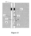
- FIG. 10 a configuration of a pair of electrodes is shown in a wrong configuration.
- the well 10 comprises a tubing 13 and a casing 11 surrounding formation 12.
- An annular 18 is formed between the casing and the tubing, which is filled with a conductive annular fluid.
- the well transducer 14 is connected through two insulated cables respectively to the electrodes 141 and 142.
- a conductive element 30 is located near the electrode 141 and connects the tubing 13 to the casing 11. With this configuration, a short circuit is realized through the conductive element 30 and the electrical signal emitted by the transducer will be attenuated.
- the electrode 141 has to be located on the conductive element 30 and preferably has to be insulated from the tubing 13.
- the conductivity of the pathway from a well dipole to a surface dipole has to be characterized.
- a method to determine this conductivity pathway can be done using Schumann resonances.
- the proposed method will monitor the Schumann-resonance spectrum at the earth surface as calibrating signal.
- the amplitudes of the various Schumann-resonance frequencies serve to normalize the signals within the geologic formation.
- the Schumann-resonance amplitudes are measured for the different resonance frequencies as function of vertical depth and normalized by the surface-signal amplitudes.
- the exponential decay length for any one frequency is monitored as a function of the vertical depth and fit to an exponential or a series of successive exponentials.
- the resulting exponents constitute the skin depth that determines the formation conductivity averaged over the interval of the exponential fit. According to the invention, a method and an apparatus are proposed to measure the resulting exponents of the Schumann-resonance decay profile.
- the method monitors at least two different resonance frequencies as a function of the vertical depth and compares them. Their ratio will be an exponential that can be inverted and together with the known frequencies yields the desired average formation conductivity.
- the method according to the invention monitors these Schumann resonances in a borehole as function of vertical depth with a wireline interrogating tool 100 suspended to a wireline cable 120 ( Figure 12 ). This measurement assumes a vertically even dissipation of the signals and thus permits to interpret the measurement as vertical conductivity profile.
- the Schumann resonances use the earth surface as conductive boundary. Hence, the electric field will be close to perpendicular and the magnetic field close to tangential to the earth surface. Consequently, vertical electric-dipole (voltage-gap) and horizontal magnetic-dipole receivers will be best suited as detectors for Schumann resonances.
- the Schumann resonances must be monitored at the surface of a survey site.
- the frequency spectrum and the relative amplitudes for the different resonances measured at the surface serve as calibration to normalize the downhole measurements.
- the downhole measurement conditions will differ from the surface conditions.
- the downhole sensor configuration may differ from the surface monitors.
- the downhole measurement may be performed in casing where the signal attenuation across the casing wall becomes a function of frequency. Therefore, the surface monitor only serves as good-quality resonance-frequency calibration and first-step amplitude calibration.
- the frequency f is implied in Hz and the conductivity ⁇ ( z ) in S/m.
- the universal normalization U 0 only serves to provide correct physical units.
- the presence of this universal signal normalization indicates that the conductivity log from the Schumann resonances may require a calibration shift on the logarithmic conductivity scale to match with some known formation conductivity.
- the apparatus according to the invention is an interrogating tool as disclosed in Figure 12 and containing a measurement sensors package for detecting electromagnetic waves: electric and magnetic fields in a natural borehole or preferably in a cased hole.
- the amplitude of the Schumann waves is on the order of 1pT, whereas most utilitarian measurements are conducted using high-intensity transients with an amplitude of approximately 10pT.
- Receivers for the Schumann-resonance monitoring are the wireless-telemetry voltage-gap receivers, or the multi-component magnetic dipoles from crosswell electromagnetic surveys, or equivalent flux-gate magnetometers, or possibly the highly sensitive SQUID detectors (Superconducting Quantum Interference Device).
- the electric-field receiver could consist of single electrodes clamped inside the casing wall to measure the potential difference at casing level and reduce any spurious effects due to the presence of completion fluids. Those electrodes have been described above, especially in Figure 2 .
- the magnetic field can be measured by highly sensitive induction-coil magnetometers.
- These receivers include a core with high magnetic permeability around which a large number of turns of copper wire are wound.
- the receiver includes a built-in preamplifier system.
- SQUID detector For magnetic field measurement, it is preferable to use a SQUID detector.
- the SQUID detector is made of two superconductors, separated by a thin insulator (Josephson junction), with a sensitivity of 0.01pT, which would theoretically permit maximum operational depths exceeding 4 ⁇ .
- a liquid nitrogen-cryogenic cooler for the SQUID is necessary for operation. This cooler is available for miniaturized application with geometric dimensions of 1 inch x 1 inch x 0.2 inch (2.5cm x 2.5cm x 0.5cm).
- Figure 15 shows a schematic drawing of the operation of a SQUID detector versus an induction coil.
- the receiver could also combine both electric and magnetic field sensors to exploit the best features of the two measurement types as disclosed above.
- the apparatus according to the invention further comprises at the surface of the well, for example in a survey site, another measurement sensors package for detecting electromagnetic waves on the surface: frequency and amplitudes of electric and magnetic fields for calibration of measurements downhole with the interrogating tool.
- the measurement sensors are conventional electric field and magnetic field sensors as disclosed or others useable on surface.
- the technique could find application in a wireline logging application or in a permanent installation.
- the receiver would be deployed in production and observation hole and would monitor the variations of the formation saturation in a time-lapse fashion.
- the proposed technique takes advantage of no active source leading to a less complicated deployment. Only passive receivers are deployed permanently.
Claims (39)
- Procédé pour recevoir et/ou transmettre des informations dans un puits foré dans une formation géologique (12) entre un premier emplacement et un deuxième emplacement, ledit puits comportant un tubage (11) communiquant avec la formation (12), le procédé comportant les étapes consistant à :(i) placer un premier transducteur (14) localisé au niveau dudit premier emplacement, ledit premier transducteur (14) comportant deux électrodes, lesquelles sont les première (141) et deuxième (142) électrodes en aval, lesdites première (141) et deuxième (142) électrodes en aval étant en contact électrique avec le tubage (11) ;(ii) placer un deuxième transducteur (15) localisé au niveau dudit deuxième emplacement, ledit deuxième transducteur comportant deux électrodes, lesquelles sont les première (151) et deuxième (152) électrodes en amont ;(iii) émettre un signal électrique avec le premier transducteur (14) en appliquant ledit signal entre les première (141) et deuxième (142) électrodes en aval ou respectivement avec le deuxième transducteur (15) en appliquant ledit signal entre les première (151) et deuxième (152) électrodes en amont ; et(iv) recevoir ledit signal électrique avec le deuxième transducteur (15) en détectant ledit signal entre les première (151) et deuxième (152) électrodes en amont ou respectivement avec le premier transducteur (14) en détectant ledit signal entre les première (141) et deuxième (142) électrodes en aval.
- Procédé selon la revendication 1, dans lequel le puits comporte en outre un troisième transducteur, ledit troisième transducteur étant localisé au niveau d'un troisième emplacement et comportant deux électrodes, lesquelles sont les première et deuxième électrodes de puits, lesdites première et deuxième électrodes de puits étant en contact électrique avec le tubage (11) ; et le procédé comportant en outre les étapes consistant à :(i) émettre un deuxième signal électrique avec le troisième transducteur en appliquant ledit deuxième signal entre les première et deuxième électrodes de puits ; et/ou(ii) recevoir un troisième signal électrique avec le troisième transducteur en détectant ledit troisième signal entre les première et deuxième électrodes de puits.
- Procédé selon la revendication 2, dans lequel le puits comporte en outre une pluralité de transducteurs supplémentaires.
- Procédé selon la revendication 1, dans lequel le puits comporte en outre un transducteur relais, ledit transducteur relais étant localisé au niveau d'un troisième emplacement et comportant deux électrodes, lesquelles sont les première et deuxième électrodes de puits, lesdites première et deuxième électrodes de puits étant en contact électrique avec le tubage (11) ; et le procédé comportant en outre les étapes consistant à :(i) recevoir le signal électrique avec le troisième transducteur en détectant ledit signal entre les première et deuxième électrodes de puits ; et(ii) émettre le signal électrique avec le troisième transducteur en appliquant ledit signal entre les première et deuxième électrodes de puits.
- Procédé selon la revendication 4, dans lequel le puits comporte en outre une pluralité de transducteurs relais supplémentaires.
- Procédé selon l'une quelconque des revendications précédentes, dans lequel ledit premier emplacement est dans le puits et ledit deuxième emplacement est au niveau de la surface du sol (20) de la formation géologique (12).
- Procédé selon l'une quelconque des revendications 1 à 5, dans lequel lesdits premier et deuxième emplacements sont dans le puits.
- Procédé selon l'une quelconque des revendications 2 à 5, dans lequel ledit troisième emplacement est dans le puits.
- Procédé selon l'une quelconque des revendications précédentes, dans lequel ledit puits comporte un tube (13) et dans lequel au moins l'une des électrodes choisies dans la liste suivants : première électrode en aval (141), deuxième électrode en aval (142), première électrode en amont (151), deuxième électrode en amont (152), première électrode de puits, deuxième électrode de puits, électrodes en provenance des transducteurs supplémentaires, est isolée électriquement du tube (13).
- Procédé selon la revendication 9, dans lequel ladite au moins une électrode est en outre isolée électriquement des autres éléments conducteurs dans le puits.
- Procédé selon l'une quelconque des revendications précédentes, dans lequel les première (141) et deuxième (142) électrodes en aval sont séparées par une première distance d1 , ladite première distance d1 étant dépendante de l'intensité du signal électrique et de la distance entre les première (141) et deuxième (142) électrodes en aval et les première (151) et deuxième (152) électrodes en amont.
- Procédé selon l'une quelconque des revendications 2 à 10, dans lequel les première (141) et deuxième (152) électrodes en aval sont séparées par une première distance d1 , ladite première distance d1 , étant dépendante de l'intensité du signal électrique et de la distance entre les première (141) et deuxième (142) électrodes en aval et les première et deuxième électrodes de puits.
- Procédé selon l'une quelconque des revendications 2 à 10, dans lequel les première et deuxième électrodes de puits sont séparées par une troisième distance d3 ladite troisième distance d3 étant dépendante du signal électrique et de la distance entre les première et deuxième électrodes de puits et les première (151) et deuxième (152) électrodes en amont.
- Procédé selon l'une quelconque des revendications précédentes, dans lequel les première (151) et deuxième (152) électrodes en amont sont en contact électrique avec la formation géologique (12) au niveau de la surface du sol (20).
- Procédé selon l'une quelconque des revendications précédentes, dans lequel ledit puits comporte un tube (13) et dans lequel la première électrode en amont (151) est en contact électrique avec le tube (13) et la deuxième électrode en amont (152) est en contact électrique avec la formation (12) au niveau de la surface du sol (20).
- Procédé selon l'une quelconque des revendications précédentes, dans lequel au moins l'un des transducteurs choisis dans la liste suivante : premier transducteur (14), deuxième transducteur (15), troisième transducteur et transducteur relais, est connecté à un capteur de mesure et/ou un équipement de surveillance / contrôle.
- Procédé selon la revendication 16, dans lequel le signal électrique contient des informations en provenance du capteur de mesure et/ou de l'équipement de surveillance / contrôle.
- Dispositif destiné à recevoir et/ou transmettre des informations dans un puits percé dans la formation géologique (12) entre un premier emplacement et un deuxième emplacement, ledit puits comportant un tubage (11) communiquant avec la formation géologique (12), le dispositif comportant :(i) un premier transducteur (14) localisé au niveau dudit premier emplacement, ledit premier transducteur (14) comportant deux électrodes, lesquelles sont des première (141) et deuxième (142) électrodes en aval, lesdites première (141) et deuxième (142) électrodes en aval étant en contact électrique avec le tubage (11) ; et(ii) un deuxième transducteur (15) localisé au niveau dudit deuxième emplacement, ledit deuxième transducteur (15) comportant deux électrodes, lesquelles sont des première (151) et deuxième (152) électrodes en amont.
- Dispositif selon la revendication 18, comportant en outre au moins un autre troisième transducteur, ledit troisième transducteur étant localisé au niveau d'un troisième emplacement et comportant deux électrodes, lesquelles sont des première et deuxième électrodes de puits, lesdites première et deuxième électrodes de puits étant en contact électrique avec le tubage (11).
- Dispositif selon la revendication 19, dans lequel le troisième transducteur est un transducteur relais.
- Dispositif selon l'une quelconque des revendications 18 à 20, dans lequel ledit premier emplacement est dans le puits et ledit deuxième emplacement se situe au niveau de la surface du sol (20) de la formation géologique (12).
- Dispositif selon l'une quelconque des revendications 18 à 20, dans lequel lesdits premier et deuxième emplacements sont dans le puits.
- Dispositif selon la revendication 19 ou 20, dans lequel ledit troisième emplacement se situe dans le puits.
- Dispositif selon l'une quelconque des revendications 18 à 23, dans lequel ledit puits comporte un tube (13) et dans lequel au moins l'une des électrodes choisies dans la liste suivante : première électrode en aval (141), deuxième électrode en aval (142), première électrode en amont (151), deuxième électrode en amont (152), première électrode de puits et deuxième électrode de puits, est isolée électriquement du tube (13).
- Dispositif selon la revendication 24, dans lequel ladite au moins une électrode est en outre isolée électriquement des autres éléments conducteurs dans le puits.
- Dispositif selon l'une quelconque des revendications 18 à 25, dans lequel les première (151) et deuxième (152) électrodes en amont sont en contact électrique avec la formation (12) au niveau de la surface du sol (20).
- Dispositif selon l'une quelconque des revendications 18 à 25, dans lequel ledit puits comporte un tube (13) et dans lequel la première électrode en amont (151) est en contact électrique avec le tube (13) et la deuxième électrode en amont (152) est en contact électrique avec la formation géologique (12) au niveau de la surface du sol (20).
- Dispositif selon l'une quelconque des revendications 18 à 27, dans lequel la première électrode en aval (141) est l'un quelconque des éléments parmi la liste suivante : un matériau composite lequel est constitué d'une couche mince de comprimé de diamant polycristallin (PDC), un ressort en arc métallique, et un calibre métallique.
- Dispositif selon l'une quelconque des revendications 18 à 28, dans lequel la deuxième électrode en aval (142) est l'un quelconque des éléments parmi la liste suivante : un matériau composite lequel est constitué d'une couche mince de comprimé de diamant polycristallin (PDC), un ressort en arc métallique, et un calibre métallique.
- Dispositif selon l'une quelconque des revendications 19 à 29, dans lequel la première électrode de puits est l'un quelconque des éléments parmi la liste suivante : un matériau composite lequel est constitué d'une couche mince de comprimé de diamant polycristallin (PDC), un ressort en arc métallique, et un calibre métallique.
- Dispositif selon l'une quelconque des revendications 19 à 30, dans lequel la deuxième électrode de puits est l'un quelconque des éléments parmi la liste suivante : un matériau composite constitué d'une couche mince de comprimé de diamant polycristallin (PDC), un ressort en arc métallique, et un calibre métallique.
- Dispositif selon l'une quelconque des revendications 18 à 31, dans lequel la première électrode en aval (141) est localisée sur une première garniture d'étanchéité (20').
- Dispositif selon l'une quelconque des revendications 18 à 32, dans lequel la deuxième électrode en aval (142) est localisée sur une deuxième garniture d'étanchéité (20'').
- Dispositif selon l'une quelconque des revendications 18 à 31, dans lequel les première (141) et deuxième (142) électrodes en aval sont localisées sur une garniture d'étanchéité en aval.
- Dispositif selon l'une quelconque des revendications 19 à 34, dans lequel la première électrode de puits est localisée sur une troisième garniture d'étanchéité.
- Dispositif selon l'une quelconque des revendications 19 à 35, dans lequel la deuxième électrode de puits est localisée sur une quatrième garniture d'étanchéité.
- Dispositif selon l'une quelconque des revendications 19 à 34, dans lequel les première et deuxième électrodes de puits sont localisées sur une garniture d'étanchéité de puits.
- Dispositif selon l'une quelconque des revendications 29 à 37, dans lequel le déploiement de la garniture d'étanchéité choisie dans la liste suivante : première garniture d'étanchéité (20'), deuxième garniture d'étanchéité (20"), troisième garniture d'étanchéité, quatrième garniture d'étanchéité, garniture d'étanchéité en aval et garniture d'étanchéité de puits, est commandé par la différence de tension entre les première (141) et deuxième (142) électrodes en aval et/ou les première et deuxième électrodes de puits.
- Dispositif selon l'une quelconque des revendications 19 à 38, dans lequel au moins l'un des transducteurs choisis dans la liste suivante : premier transducteur (14), deuxième transducteur (15) et au moins un autre transducteur, est connecté à un capteur de mesure et/ou à un équipement de surveillance / de contrôle.
Priority Applications (13)
| Application Number | Priority Date | Filing Date | Title |
|---|---|---|---|
| ES05291628T ES2339361T3 (es) | 2005-07-29 | 2005-07-29 | Metodo y aparato para transmitir o recibir informacion entre un equipo de fondo de pozo y la superficie. |
| EP05291628A EP1748151B1 (fr) | 2005-07-29 | 2005-07-29 | Méthode et dispositif pour la transmission ou réception d'information entre un dispositif de fond et la surface |
| DK05291628.5T DK1748151T3 (da) | 2005-07-29 | 2005-07-29 | Fremgangsmåde og apparat til at transmittere eller modtage information mellem et borehulsudstyr og overfladen |
| AT05291628T ATE454532T1 (de) | 2005-07-29 | 2005-07-29 | Verfahren und vorrichtung zum senden oder empfangen von information zwischen ein bohrlochmessgerät und der oberfläche |
| DE602005018766T DE602005018766D1 (de) | 2005-07-29 | 2005-07-29 | Verfahren und Vorrichtung zum Senden oder Empfangen von Information zwischen ein Bohrlochmessgerät und der Oberfläche |
| BRPI0614908-1A BRPI0614908A2 (pt) | 2005-07-29 | 2006-07-28 | método de recepção e/ou transmissão de informações em um poço perfurado em uma formação geológica entre uma primeira localização e uma segunda localização, aparelho para recepção e/ou transmissão de informações em um poço perfurado na formação geológica entre uma primeira localização e uma segunda localização, método para determinação do perfil de condutividade de uma formação de um poço entre uma primeira localização em uma superfìcie e uma segunda localização em um furo perfurado, e aparelho para determinação do perfil de condutividade de uma formação de um poço entre uma primeira localização em uma superfìcie e uma segunda localização em um furo perfurado |
| CN2006800353473A CN101273285B (zh) | 2005-07-29 | 2006-07-28 | 用于在井下器材和地面之间传送或接收信息的方法和设备 |
| RU2008107770/28A RU2419820C2 (ru) | 2005-07-29 | 2006-07-28 | Способ и устройство для передачи или приема информации между внутрискважинным оборудованием и поверхностью |
| MX2008001096A MX2008001096A (es) | 2005-07-29 | 2006-07-28 | Metodo y aparato para transmitir o recibir informacion entre un equipo situado en el fondo de la perforacion y la superficie. |
| MYPI20063641A MY142420A (en) | 2005-07-29 | 2006-07-28 | Method and apparatus for transmitting or receiving information between a downhole equipment and surface |
| US11/996,996 US8789620B2 (en) | 2005-07-29 | 2006-07-28 | Method and apparatus for transmitting or receiving information between downhole equipment and surface |
| PCT/IB2006/002110 WO2007023341A2 (fr) | 2005-07-29 | 2006-07-28 | Procede et appareil d'echange d'informations entre un equipement de fond et la surface |
| US14/325,374 US9359888B2 (en) | 2005-07-29 | 2014-07-08 | Method and apparatus for transmitting or receiving information between a downhole equipment and surface |
Applications Claiming Priority (1)
| Application Number | Priority Date | Filing Date | Title |
|---|---|---|---|
| EP05291628A EP1748151B1 (fr) | 2005-07-29 | 2005-07-29 | Méthode et dispositif pour la transmission ou réception d'information entre un dispositif de fond et la surface |
Publications (2)
| Publication Number | Publication Date |
|---|---|
| EP1748151A1 EP1748151A1 (fr) | 2007-01-31 |
| EP1748151B1 true EP1748151B1 (fr) | 2010-01-06 |
Family
ID=35479858
Family Applications (1)
| Application Number | Title | Priority Date | Filing Date |
|---|---|---|---|
| EP05291628A Not-in-force EP1748151B1 (fr) | 2005-07-29 | 2005-07-29 | Méthode et dispositif pour la transmission ou réception d'information entre un dispositif de fond et la surface |
Country Status (12)
| Country | Link |
|---|---|
| US (2) | US8789620B2 (fr) |
| EP (1) | EP1748151B1 (fr) |
| CN (1) | CN101273285B (fr) |
| AT (1) | ATE454532T1 (fr) |
| BR (1) | BRPI0614908A2 (fr) |
| DE (1) | DE602005018766D1 (fr) |
| DK (1) | DK1748151T3 (fr) |
| ES (1) | ES2339361T3 (fr) |
| MX (1) | MX2008001096A (fr) |
| MY (1) | MY142420A (fr) |
| RU (1) | RU2419820C2 (fr) |
| WO (1) | WO2007023341A2 (fr) |
Families Citing this family (41)
| Publication number | Priority date | Publication date | Assignee | Title |
|---|---|---|---|---|
| GB2444276B (en) * | 2006-12-02 | 2009-06-03 | Schlumberger Holdings | System and method for qualitative and quantitative analysis of gaseous components of multiphase hydrocarbon mixtures |
| US8773278B2 (en) | 2007-12-21 | 2014-07-08 | Schlumberger Technology Corporation | Apparatus for receiving and transmitting signals in electromagnetic telemetry system used in a wellbore |
| EP2329300B1 (fr) * | 2008-07-31 | 2020-12-02 | Halliburton Energy Services Inc. | Procédé et système de répéteur télémétrique électromagnétique |
| EP2278358A1 (fr) * | 2009-07-22 | 2011-01-26 | Leica Geosystems AG | Procédé et système de détection de la proximité d'une structure conductrice enterrée |
| US8746367B2 (en) | 2010-04-28 | 2014-06-10 | Baker Hughes Incorporated | Apparatus and methods for detecting performance data in an earth-boring drilling tool |
| US8695729B2 (en) | 2010-04-28 | 2014-04-15 | Baker Hughes Incorporated | PDC sensing element fabrication process and tool |
| US8757291B2 (en) | 2010-04-28 | 2014-06-24 | Baker Hughes Incorporated | At-bit evaluation of formation parameters and drilling parameters |
| WO2012037390A2 (fr) * | 2010-09-15 | 2012-03-22 | Aronstam Peter S | Câble d'alimentation d'antenne tubulaire extensible pour une communication e/m à travers le tubage |
| US8800685B2 (en) | 2010-10-29 | 2014-08-12 | Baker Hughes Incorporated | Drill-bit seismic with downhole sensors |
| IT1403940B1 (it) * | 2011-02-16 | 2013-11-08 | Eni Spa | Sistema di rilevamento di formazioni geologiche |
| GB2496440A (en) | 2011-11-11 | 2013-05-15 | Expro North Sea Ltd | Down-hole structure with an electrode sleeve |
| RU2631099C2 (ru) * | 2011-12-13 | 2017-09-18 | Цой Валентин | Устройство для электрического каротажа через металлическую колонну |
| US9309761B2 (en) * | 2012-05-16 | 2016-04-12 | Baker Hughes Incorporated | Communication system for extended reach wells |
| AU2013271387A1 (en) * | 2012-06-07 | 2015-01-15 | California Institute Of Technology | Communication in pipes using acoustic modems that provide minimal obstruction to fluid flow |
| US9927547B2 (en) * | 2012-07-02 | 2018-03-27 | Baker Hughes, A Ge Company, Llc | Power generating communication device |
| GB2506123C (en) * | 2012-09-19 | 2024-02-21 | Expro North Sea Ltd | Downhole communication |
| RU2539354C2 (ru) * | 2012-09-20 | 2015-01-20 | Открытое акционерное общество "Омский научно-исследовательский институт приборостроения" (ОАО "ОНИИП") | Автоматизированная система испытаний антенн |
| CN103731191A (zh) * | 2012-10-11 | 2014-04-16 | 中国石油化工股份有限公司 | 一种电磁随钻测量系统的信号传输中继器 |
| US9664037B2 (en) | 2013-03-07 | 2017-05-30 | Evolution Engineering Inc. | Detection of downhole data telemetry signals |
| CA2913587A1 (fr) * | 2013-07-25 | 2015-01-29 | Halliburton Energy Services Inc. | Outil et procede de telemetrie |
| CN105518245B (zh) | 2013-09-05 | 2018-08-07 | 开拓工程股份有限公司 | 跨钻柱中的电绝缘间隙发送数据 |
| EA032746B1 (ru) | 2014-06-23 | 2019-07-31 | Эволюшн Инжиниринг Инк. | Оптимизация передачи скважинных данных с помощью наддолотных датчиков и узлов |
| US9638028B2 (en) | 2014-08-27 | 2017-05-02 | Schlumberger Technology Corporation | Electromagnetic telemetry for measurement and logging while drilling and magnetic ranging between wellbores |
| CN104533403A (zh) * | 2014-11-25 | 2015-04-22 | 牡丹江天擎科技有限公司 | 一种黑色金属涂层的侧向电极环 |
| WO2016100672A1 (fr) * | 2014-12-18 | 2016-06-23 | Schlumberger Canada Limited | Procédés et systèmes pour renforcer l'intensité d'un signal électromagnétique de télémétrie détecté en surface |
| WO2016100736A1 (fr) * | 2014-12-18 | 2016-06-23 | Schlumberger Canada Limited | Configurations d'antenne de surface dipôle électrique pour télémesure par instrument électromagnétique dans un puits de forage |
| WO2016148697A1 (fr) * | 2015-03-17 | 2016-09-22 | Halliburton Energy Services, Inc. | Communications sans fil localisées dans un environnement de fond de trou |
| US10378337B2 (en) | 2015-05-29 | 2019-08-13 | Schlumberger Technology Corporation | EM-telemetry remote sensing wireless network and methods of using the same |
| WO2017023186A1 (fr) | 2015-08-06 | 2017-02-09 | Ventora Technologies Ag | Procédé et dispositif pour traitement sonochimique de puits et de réservoir |
| WO2017083152A1 (fr) | 2015-11-13 | 2017-05-18 | Schlumberger Technology Corporation | Procédé de pose d'électrodes de surface pour télémétrie électromagnétique |
| US10113419B2 (en) | 2016-01-25 | 2018-10-30 | Halliburton Energy Services, Inc. | Electromagnetic telemetry using a transceiver in an adjacent wellbore |
| CA3014061C (fr) * | 2016-02-19 | 2020-04-14 | Scientific Drilling International, Inc. | Systemes et procedes de telemetrie electromagnetique souterraine |
| BR112019001498A2 (pt) * | 2016-08-12 | 2019-05-07 | Halliburton Energy Services, Inc. | método de monitoramento de corrosão de múltiplas colunas e sistema de monitoramento de corrosão de múltiplas colunas |
| US11119242B2 (en) | 2017-03-24 | 2021-09-14 | Halliburton Energy Services, Inc. | Active noise cancellation in electromagnetic telemetry |
| CN107560721B (zh) * | 2017-08-25 | 2023-11-10 | 中国石油化工股份有限公司 | 一种盐穴储气库安全监听分析系统及方法 |
| US20210404326A1 (en) * | 2018-12-10 | 2021-12-30 | Halliburton Energy Services, Inc. | Electromagnetic telemetry system |
| CN110703344B (zh) * | 2019-10-18 | 2021-03-30 | 中国科学院地质与地球物理研究所 | 一种隐伏资源预测方法及岩石电磁学测井系统 |
| US11460446B2 (en) * | 2020-04-21 | 2022-10-04 | Baker Hughes Oilfield Operations Llc | Estimation of formation and/or downhole component properties using electromagnetic acoustic sensing |
| RU2745858C1 (ru) * | 2020-06-03 | 2021-04-02 | Общество с ограниченной ответственностью "Научно-технологический центр Геомеханика" | Способ мониторинга скважинных забойных параметров и устройство для его осуществления |
| CN113266343B (zh) * | 2021-06-29 | 2022-04-01 | 华中科技大学 | 一种无线信号传输系统 |
| CN114635672A (zh) * | 2021-12-30 | 2022-06-17 | 中国石油天然气集团有限公司 | 一种页岩气井下生产动态监测方法和系统 |
Family Cites Families (19)
| Publication number | Priority date | Publication date | Assignee | Title |
|---|---|---|---|---|
| US4181014A (en) * | 1978-05-04 | 1980-01-01 | Scientific Drilling Controls, Inc. | Remote well signalling apparatus and methods |
| US4808929A (en) * | 1983-11-14 | 1989-02-28 | Schlumberger Technology Corporation | Shielded induction sensor for well logging |
| US4616702A (en) * | 1984-05-01 | 1986-10-14 | Comdisco Resources, Inc. | Tool and combined tool support and casing section for use in transmitting data up a well |
| US4780678A (en) * | 1984-05-31 | 1988-10-25 | Schlumberger Technology Corporation | Apparatus for microinductive investigation of earth formations |
| US5570024A (en) * | 1986-11-04 | 1996-10-29 | Paramagnetic Logging, Inc. | Determining resistivity of a formation adjacent to a borehole having casing using multiple electrodes and with resistances being defined between the electrodes |
| US4839644A (en) | 1987-06-10 | 1989-06-13 | Schlumberger Technology Corp. | System and method for communicating signals in a cased borehole having tubing |
| US5130706A (en) * | 1991-04-22 | 1992-07-14 | Scientific Drilling International | Direct switching modulation for electromagnetic borehole telemetry |
| FR2681461B1 (fr) | 1991-09-12 | 1993-11-19 | Geoservices | Procede et agencement pour la transmission d'informations, de parametres et de donnees a un organe electro-magnetique de reception ou de commande associe a une canalisation souterraine de grande longueur. |
| US5883516A (en) * | 1996-07-31 | 1999-03-16 | Scientific Drilling International | Apparatus and method for electric field telemetry employing component upper and lower housings in a well pipestring |
| US6396276B1 (en) * | 1996-07-31 | 2002-05-28 | Scientific Drilling International | Apparatus and method for electric field telemetry employing component upper and lower housings in a well pipestring |
| CA2666251C (fr) * | 1999-12-17 | 2012-02-21 | Geosensors Inc. | Dispositif de detection electromagnetique modulaire avec etalonnage ameliore |
| US6633164B2 (en) * | 2000-01-24 | 2003-10-14 | Shell Oil Company | Measuring focused through-casing resistivity using induction chokes and also using well casing as the formation contact electrodes |
| US6817412B2 (en) * | 2000-01-24 | 2004-11-16 | Shell Oil Company | Method and apparatus for the optimal predistortion of an electromagnetic signal in a downhole communication system |
| FR2820167B1 (fr) * | 2001-01-26 | 2004-06-04 | Cie Du Sol | Train de tiges de forage permettant la transmission d'informations |
| US7000697B2 (en) | 2001-11-19 | 2006-02-21 | Schlumberger Technology Corporation | Downhole measurement apparatus and technique |
| US6970099B2 (en) * | 2001-12-04 | 2005-11-29 | Ryan Energy Technologies Inc. | Apparatus, system, and method for detecting and reimpressing electrical charge disturbances on a drill-pipe |
| US6909667B2 (en) * | 2002-02-13 | 2005-06-21 | Halliburton Energy Services, Inc. | Dual channel downhole telemetry |
| US6975121B2 (en) * | 2004-03-22 | 2005-12-13 | Kjt Enterprises, Inc. | System for measuring earth formation resistivity through and electrically conductive wellbore casing |
| US7202671B2 (en) * | 2004-08-05 | 2007-04-10 | Kjt Enterprises, Inc. | Method and apparatus for measuring formation conductivities from within cased wellbores by combined measurement of casing current leakage and electromagnetic response |
-
2005
- 2005-07-29 DK DK05291628.5T patent/DK1748151T3/da active
- 2005-07-29 ES ES05291628T patent/ES2339361T3/es active Active
- 2005-07-29 EP EP05291628A patent/EP1748151B1/fr not_active Not-in-force
- 2005-07-29 AT AT05291628T patent/ATE454532T1/de not_active IP Right Cessation
- 2005-07-29 DE DE602005018766T patent/DE602005018766D1/de active Active
-
2006
- 2006-07-28 CN CN2006800353473A patent/CN101273285B/zh not_active Expired - Fee Related
- 2006-07-28 BR BRPI0614908-1A patent/BRPI0614908A2/pt not_active IP Right Cessation
- 2006-07-28 US US11/996,996 patent/US8789620B2/en not_active Expired - Fee Related
- 2006-07-28 MX MX2008001096A patent/MX2008001096A/es active IP Right Grant
- 2006-07-28 RU RU2008107770/28A patent/RU2419820C2/ru not_active IP Right Cessation
- 2006-07-28 MY MYPI20063641A patent/MY142420A/en unknown
- 2006-07-28 WO PCT/IB2006/002110 patent/WO2007023341A2/fr active Application Filing
-
2014
- 2014-07-08 US US14/325,374 patent/US9359888B2/en active Active
Also Published As
| Publication number | Publication date |
|---|---|
| EP1748151A1 (fr) | 2007-01-31 |
| ATE454532T1 (de) | 2010-01-15 |
| US8789620B2 (en) | 2014-07-29 |
| BRPI0614908A2 (pt) | 2011-04-19 |
| WO2007023341A2 (fr) | 2007-03-01 |
| US9359888B2 (en) | 2016-06-07 |
| US20110168446A1 (en) | 2011-07-14 |
| DK1748151T3 (da) | 2010-05-10 |
| CN101273285A (zh) | 2008-09-24 |
| ES2339361T3 (es) | 2010-05-19 |
| RU2008107770A (ru) | 2009-09-10 |
| MX2008001096A (es) | 2008-03-11 |
| DE602005018766D1 (de) | 2010-02-25 |
| MY142420A (en) | 2010-11-30 |
| WO2007023341A3 (fr) | 2007-12-27 |
| US20140318767A1 (en) | 2014-10-30 |
| RU2419820C2 (ru) | 2011-05-27 |
| CN101273285B (zh) | 2012-05-30 |
Similar Documents
| Publication | Publication Date | Title |
|---|---|---|
| EP1748151B1 (fr) | Méthode et dispositif pour la transmission ou réception d'information entre un dispositif de fond et la surface | |
| US7140434B2 (en) | Sensor system | |
| CA2959346C (fr) | Telemetrie electromagnetique pour la mesure et la diagraphie en cours de forage et la telemetrie magnetique entre des puits de forage | |
| NL1017664C2 (nl) | Systeem en werkwijze voor het controleren van een reservoir en plaatsen van een boorgat onder gebruik maken van een buis. | |
| US6534986B2 (en) | Permanently emplaced electromagnetic system and method for measuring formation resistivity adjacent to and between wells | |
| CA2316044C (fr) | Surveillance de reservoir a travers un raccord de tubage modifie | |
| US6691779B1 (en) | Wellbore antennae system and method | |
| US6693553B1 (en) | Reservoir management system and method | |
| RU2405932C2 (ru) | Способы и устройства для осуществления связи сквозь обсадную колонну | |
| US9035657B2 (en) | Electromagnetic logging between a cased borehole and surface | |
| WO2011041248A2 (fr) | Diagraphie électromagnétique entre un trou de forage gainé et la surface | |
| US10227868B2 (en) | Electromagnetic telemetry using capacitive surface electrodes | |
| US6597177B1 (en) | Through casing resistivity measurement in permanently installed downhole production environment | |
| AU6244300A (en) | Wellbore antennae system and method | |
| AU4587602A (en) | Wellbore antennae system and method |
Legal Events
| Date | Code | Title | Description |
|---|---|---|---|
| PUAI | Public reference made under article 153(3) epc to a published international application that has entered the european phase |
Free format text: ORIGINAL CODE: 0009012 |
|
| AK | Designated contracting states |
Kind code of ref document: A1 Designated state(s): AT BE BG CH CY CZ DE DK EE ES FI FR GB GR HU IE IS IT LI LT LU LV MC NL PL PT RO SE SI SK TR |
|
| AX | Request for extension of the european patent |
Extension state: AL BA HR MK YU |
|
| 17P | Request for examination filed |
Effective date: 20070629 |
|
| 17Q | First examination report despatched |
Effective date: 20070821 |
|
| AKX | Designation fees paid |
Designated state(s): AT BE BG CH CY CZ DE DK EE ES FI FR GB GR HU IE IS IT LI LT LU LV MC NL PL PT RO SE SI SK TR |
|
| GRAP | Despatch of communication of intention to grant a patent |
Free format text: ORIGINAL CODE: EPIDOSNIGR1 |
|
| GRAS | Grant fee paid |
Free format text: ORIGINAL CODE: EPIDOSNIGR3 |
|
| GRAA | (expected) grant |
Free format text: ORIGINAL CODE: 0009210 |
|
| AK | Designated contracting states |
Kind code of ref document: B1 Designated state(s): AT BE BG CH CY CZ DE DK EE ES FI FR GB GR HU IE IS IT LI LT LU LV MC NL PL PT RO SE SI SK TR |
|
| REG | Reference to a national code |
Ref country code: GB Ref legal event code: FG4D |
|
| REG | Reference to a national code |
Ref country code: CH Ref legal event code: EP |
|
| REG | Reference to a national code |
Ref country code: IE Ref legal event code: FG4D |
|
| REF | Corresponds to: |
Ref document number: 602005018766 Country of ref document: DE Date of ref document: 20100225 Kind code of ref document: P |
|
| REG | Reference to a national code |
Ref country code: NL Ref legal event code: T3 |
|
| REG | Reference to a national code |
Ref country code: DK Ref legal event code: T3 |
|
| REG | Reference to a national code |
Ref country code: ES Ref legal event code: FG2A Ref document number: 2339361 Country of ref document: ES Kind code of ref document: T3 |
|
| RAP2 | Party data changed (patent owner data changed or rights of a patent transferred) |
Owner name: PRAD RESEARCH AND DEVELOPMENT LIMITED Owner name: SCHLUMBERGER HOLDINGS LIMITED Owner name: SCHLUMBERGER TECHNOLOGY B.V. Owner name: SERVICES PETROLIERS SCHLUMBERGER |
|
| PG25 | Lapsed in a contracting state [announced via postgrant information from national office to epo] |
Ref country code: SI Free format text: LAPSE BECAUSE OF FAILURE TO SUBMIT A TRANSLATION OF THE DESCRIPTION OR TO PAY THE FEE WITHIN THE PRESCRIBED TIME-LIMIT Effective date: 20100106 |
|
| LTIE | Lt: invalidation of european patent or patent extension |
Effective date: 20100106 |
|
| PG25 | Lapsed in a contracting state [announced via postgrant information from national office to epo] |
Ref country code: AT Free format text: LAPSE BECAUSE OF FAILURE TO SUBMIT A TRANSLATION OF THE DESCRIPTION OR TO PAY THE FEE WITHIN THE PRESCRIBED TIME-LIMIT Effective date: 20100106 |
|
| PG25 | Lapsed in a contracting state [announced via postgrant information from national office to epo] |
Ref country code: IS Free format text: LAPSE BECAUSE OF FAILURE TO SUBMIT A TRANSLATION OF THE DESCRIPTION OR TO PAY THE FEE WITHIN THE PRESCRIBED TIME-LIMIT Effective date: 20100506 Ref country code: LT Free format text: LAPSE BECAUSE OF FAILURE TO SUBMIT A TRANSLATION OF THE DESCRIPTION OR TO PAY THE FEE WITHIN THE PRESCRIBED TIME-LIMIT Effective date: 20100106 Ref country code: PT Free format text: LAPSE BECAUSE OF FAILURE TO SUBMIT A TRANSLATION OF THE DESCRIPTION OR TO PAY THE FEE WITHIN THE PRESCRIBED TIME-LIMIT Effective date: 20100506 |
|
| PG25 | Lapsed in a contracting state [announced via postgrant information from national office to epo] |
Ref country code: FI Free format text: LAPSE BECAUSE OF FAILURE TO SUBMIT A TRANSLATION OF THE DESCRIPTION OR TO PAY THE FEE WITHIN THE PRESCRIBED TIME-LIMIT Effective date: 20100106 Ref country code: LV Free format text: LAPSE BECAUSE OF FAILURE TO SUBMIT A TRANSLATION OF THE DESCRIPTION OR TO PAY THE FEE WITHIN THE PRESCRIBED TIME-LIMIT Effective date: 20100106 Ref country code: PL Free format text: LAPSE BECAUSE OF FAILURE TO SUBMIT A TRANSLATION OF THE DESCRIPTION OR TO PAY THE FEE WITHIN THE PRESCRIBED TIME-LIMIT Effective date: 20100106 |
|
| PG25 | Lapsed in a contracting state [announced via postgrant information from national office to epo] |
Ref country code: SE Free format text: LAPSE BECAUSE OF FAILURE TO SUBMIT A TRANSLATION OF THE DESCRIPTION OR TO PAY THE FEE WITHIN THE PRESCRIBED TIME-LIMIT Effective date: 20100106 Ref country code: GR Free format text: LAPSE BECAUSE OF FAILURE TO SUBMIT A TRANSLATION OF THE DESCRIPTION OR TO PAY THE FEE WITHIN THE PRESCRIBED TIME-LIMIT Effective date: 20100407 Ref country code: EE Free format text: LAPSE BECAUSE OF FAILURE TO SUBMIT A TRANSLATION OF THE DESCRIPTION OR TO PAY THE FEE WITHIN THE PRESCRIBED TIME-LIMIT Effective date: 20100106 Ref country code: CY Free format text: LAPSE BECAUSE OF FAILURE TO SUBMIT A TRANSLATION OF THE DESCRIPTION OR TO PAY THE FEE WITHIN THE PRESCRIBED TIME-LIMIT Effective date: 20100106 Ref country code: BE Free format text: LAPSE BECAUSE OF FAILURE TO SUBMIT A TRANSLATION OF THE DESCRIPTION OR TO PAY THE FEE WITHIN THE PRESCRIBED TIME-LIMIT Effective date: 20100106 |
|
| PGFP | Annual fee paid to national office [announced via postgrant information from national office to epo] |
Ref country code: ES Payment date: 20100813 Year of fee payment: 6 Ref country code: NL Payment date: 20100707 Year of fee payment: 6 |
|
| PLBE | No opposition filed within time limit |
Free format text: ORIGINAL CODE: 0009261 |
|
| STAA | Information on the status of an ep patent application or granted ep patent |
Free format text: STATUS: NO OPPOSITION FILED WITHIN TIME LIMIT |
|
| PG25 | Lapsed in a contracting state [announced via postgrant information from national office to epo] |
Ref country code: BG Free format text: LAPSE BECAUSE OF FAILURE TO SUBMIT A TRANSLATION OF THE DESCRIPTION OR TO PAY THE FEE WITHIN THE PRESCRIBED TIME-LIMIT Effective date: 20100406 Ref country code: CZ Free format text: LAPSE BECAUSE OF FAILURE TO SUBMIT A TRANSLATION OF THE DESCRIPTION OR TO PAY THE FEE WITHIN THE PRESCRIBED TIME-LIMIT Effective date: 20100106 Ref country code: SK Free format text: LAPSE BECAUSE OF FAILURE TO SUBMIT A TRANSLATION OF THE DESCRIPTION OR TO PAY THE FEE WITHIN THE PRESCRIBED TIME-LIMIT Effective date: 20100106 |
|
| PGFP | Annual fee paid to national office [announced via postgrant information from national office to epo] |
Ref country code: IT Payment date: 20100724 Year of fee payment: 6 |
|
| 26N | No opposition filed |
Effective date: 20101007 |
|
| PG25 | Lapsed in a contracting state [announced via postgrant information from national office to epo] |
Ref country code: MC Free format text: LAPSE BECAUSE OF NON-PAYMENT OF DUE FEES Effective date: 20100731 |
|
| REG | Reference to a national code |
Ref country code: CH Ref legal event code: PL |
|
| PG25 | Lapsed in a contracting state [announced via postgrant information from national office to epo] |
Ref country code: LI Free format text: LAPSE BECAUSE OF NON-PAYMENT OF DUE FEES Effective date: 20100731 Ref country code: CH Free format text: LAPSE BECAUSE OF NON-PAYMENT OF DUE FEES Effective date: 20100731 |
|
| PG25 | Lapsed in a contracting state [announced via postgrant information from national office to epo] |
Ref country code: IE Free format text: LAPSE BECAUSE OF NON-PAYMENT OF DUE FEES Effective date: 20100729 |
|
| REG | Reference to a national code |
Ref country code: NL Ref legal event code: V1 Effective date: 20120201 |
|
| PG25 | Lapsed in a contracting state [announced via postgrant information from national office to epo] |
Ref country code: NL Free format text: LAPSE BECAUSE OF NON-PAYMENT OF DUE FEES Effective date: 20120201 Ref country code: IT Free format text: LAPSE BECAUSE OF NON-PAYMENT OF DUE FEES Effective date: 20110729 |
|
| PG25 | Lapsed in a contracting state [announced via postgrant information from national office to epo] |
Ref country code: HU Free format text: LAPSE BECAUSE OF FAILURE TO SUBMIT A TRANSLATION OF THE DESCRIPTION OR TO PAY THE FEE WITHIN THE PRESCRIBED TIME-LIMIT Effective date: 20100707 Ref country code: LU Free format text: LAPSE BECAUSE OF NON-PAYMENT OF DUE FEES Effective date: 20100729 |
|
| PG25 | Lapsed in a contracting state [announced via postgrant information from national office to epo] |
Ref country code: TR Free format text: LAPSE BECAUSE OF FAILURE TO SUBMIT A TRANSLATION OF THE DESCRIPTION OR TO PAY THE FEE WITHIN THE PRESCRIBED TIME-LIMIT Effective date: 20100106 |
|
| REG | Reference to a national code |
Ref country code: ES Ref legal event code: FD2A Effective date: 20131029 |
|
| PG25 | Lapsed in a contracting state [announced via postgrant information from national office to epo] |
Ref country code: ES Free format text: LAPSE BECAUSE OF NON-PAYMENT OF DUE FEES Effective date: 20110730 |
|
| PGFP | Annual fee paid to national office [announced via postgrant information from national office to epo] |
Ref country code: RO Payment date: 20140612 Year of fee payment: 10 |
|
| PGFP | Annual fee paid to national office [announced via postgrant information from national office to epo] |
Ref country code: DE Payment date: 20140724 Year of fee payment: 10 |
|
| PGFP | Annual fee paid to national office [announced via postgrant information from national office to epo] |
Ref country code: GB Payment date: 20140723 Year of fee payment: 10 Ref country code: FR Payment date: 20140708 Year of fee payment: 10 |
|
| REG | Reference to a national code |
Ref country code: DE Ref legal event code: R119 Ref document number: 602005018766 Country of ref document: DE |
|
| GBPC | Gb: european patent ceased through non-payment of renewal fee |
Effective date: 20150729 |
|
| PG25 | Lapsed in a contracting state [announced via postgrant information from national office to epo] |
Ref country code: GB Free format text: LAPSE BECAUSE OF NON-PAYMENT OF DUE FEES Effective date: 20150729 Ref country code: DE Free format text: LAPSE BECAUSE OF NON-PAYMENT OF DUE FEES Effective date: 20160202 |
|
| REG | Reference to a national code |
Ref country code: FR Ref legal event code: ST Effective date: 20160331 |
|
| PG25 | Lapsed in a contracting state [announced via postgrant information from national office to epo] |
Ref country code: FR Free format text: LAPSE BECAUSE OF NON-PAYMENT OF DUE FEES Effective date: 20150731 Ref country code: RO Free format text: LAPSE BECAUSE OF NON-PAYMENT OF DUE FEES Effective date: 20150729 |
|
| PGFP | Annual fee paid to national office [announced via postgrant information from national office to epo] |
Ref country code: DK Payment date: 20160712 Year of fee payment: 12 |
|
| REG | Reference to a national code |
Ref country code: DK Ref legal event code: EBP Effective date: 20170731 |
|
| PG25 | Lapsed in a contracting state [announced via postgrant information from national office to epo] |
Ref country code: DK Free format text: LAPSE BECAUSE OF NON-PAYMENT OF DUE FEES Effective date: 20170731 |