EP1747472B1 - Faseroptisches sensorverfahren und vorrichtung - Google Patents
Faseroptisches sensorverfahren und vorrichtung Download PDFInfo
- Publication number
- EP1747472B1 EP1747472B1 EP05748527.8A EP05748527A EP1747472B1 EP 1747472 B1 EP1747472 B1 EP 1747472B1 EP 05748527 A EP05748527 A EP 05748527A EP 1747472 B1 EP1747472 B1 EP 1747472B1
- Authority
- EP
- European Patent Office
- Prior art keywords
- sensor
- fibre optic
- fibre
- optic sensor
- disturbance
- Prior art date
- Legal status (The legal status is an assumption and is not a legal conclusion. Google has not performed a legal analysis and makes no representation as to the accuracy of the status listed.)
- Expired - Lifetime
Links
Images


Classifications
-
- G—PHYSICS
- G01—MEASURING; TESTING
- G01M—TESTING STATIC OR DYNAMIC BALANCE OF MACHINES OR STRUCTURES; TESTING OF STRUCTURES OR APPARATUS, NOT OTHERWISE PROVIDED FOR
- G01M11/00—Testing of optical apparatus; Testing structures by optical methods not otherwise provided for
- G01M11/08—Testing mechanical properties
- G01M11/083—Testing mechanical properties by using an optical fiber in contact with the device under test [DUT]
-
- G—PHYSICS
- G01—MEASURING; TESTING
- G01M—TESTING STATIC OR DYNAMIC BALANCE OF MACHINES OR STRUCTURES; TESTING OF STRUCTURES OR APPARATUS, NOT OTHERWISE PROVIDED FOR
- G01M3/00—Investigating fluid-tightness of structures
- G01M3/02—Investigating fluid-tightness of structures by using fluid or vacuum
- G01M3/04—Investigating fluid-tightness of structures by using fluid or vacuum by detecting the presence of fluid at the leakage point
- G01M3/042—Investigating fluid-tightness of structures by using fluid or vacuum by detecting the presence of fluid at the leakage point by using materials which expand, contract, disintegrate, or decompose in contact with a fluid
- G01M3/045—Investigating fluid-tightness of structures by using fluid or vacuum by detecting the presence of fluid at the leakage point by using materials which expand, contract, disintegrate, or decompose in contact with a fluid with electrical detection means
- G01M3/047—Investigating fluid-tightness of structures by using fluid or vacuum by detecting the presence of fluid at the leakage point by using materials which expand, contract, disintegrate, or decompose in contact with a fluid with electrical detection means with photo-electrical detection means, e.g. using optical fibres
-
- G—PHYSICS
- G08—SIGNALLING
- G08B—SIGNALLING SYSTEMS, e.g. PERSONAL CALLING SYSTEMS; ORDER TELEGRAPHS; ALARM SYSTEMS
- G08B13/00—Burglar, theft or intruder alarms
- G08B13/18—Actuation by interference with heat, light, or radiation of shorter wavelength; Actuation by intruding sources of heat, light, or radiation of shorter wavelength
- G08B13/181—Actuation by interference with heat, light, or radiation of shorter wavelength; Actuation by intruding sources of heat, light, or radiation of shorter wavelength using active radiation detection systems
- G08B13/183—Actuation by interference with heat, light, or radiation of shorter wavelength; Actuation by intruding sources of heat, light, or radiation of shorter wavelength using active radiation detection systems by interruption of a radiation beam or barrier
- G08B13/186—Actuation by interference with heat, light, or radiation of shorter wavelength; Actuation by intruding sources of heat, light, or radiation of shorter wavelength using active radiation detection systems by interruption of a radiation beam or barrier using light guides, e.g. optical fibres
Definitions
- This invention relates to a method of identifying a disturbance of interest using a fibre optic interferometer, and finding the location of the disturbance by using a separate sensor system.
- Disturbances of interest can be, for example, the breaking of reinforcement wires in concrete pipe, the breaking of wires in suspension cables, a pipeline leak, or an intrusion by human or vehicle.
- Fibre optic sensors exist which can monitor events over a distance of twenty kilometers or more, and which can be operated with relatively low power. Such fibre optic sensors can detect acoustic and seismic disturbances, such as for example the footfalls of an intruder near a monitored perimeter, the noises associated with intentional damage of a monitored piece of infrastructure such as an electrical or communications cable, the noise of a leak in a pipeline, or the breaking of a reinforcing wire in a concrete pipeline or a wire in a bridge cable. Some such sensors have spaced sensing gratings, spaced by shielded portions, so that the location of a disturbance can be found by determining at which grating(s) the disturbance is noted. Others use pulsed laser light, where reflected signals caused by a disturbance are reflected back to the origin and the location from which the signals came is determined by the time lag from the pulse to the reception of the reflected signal.
- Such fibre optic sensors have not been very effective, because many different types of disturbance can trigger a response. Once a response is triggered, the location from which it came must be investigated to determine whether a condition requiring corrective action is present. Further, sensors which depend on the reflection of a pulse may miss or misinterpret transient effects which have their maximum effect at a time when the pulse is not scanning the particular location where they occur.
- Interferometric sensors are known which are sensitive to the measurand for a long length, for example, the entire length of the fibre optic sensor. Because the entire length, or a long length in the area of interest, is sensitive to the measurand, a signal indicating a disturbance is acquired at or very close to the source of the disturbance. This gives an advantage in signal-to-noise ratio, in that the sensor is not displaced longitudinally from the disturbance along the fibre, as is the case where there are spaced, fixed sensors. Because the distance from the nearest sensing point to the source of the disturbance is minimized, the deterioration of the signal-to-noise ratio relating from signal attenuation with distance is also minimized.
- Interferometric sensors are well known in the art, and several types are known, such as a Sagnac effect interferometric sensor shown in Udd USP 5,636,021 or a Michelson interferometric sensor as shown in Jones et al USP 4,725,143 .
- the location of the disturbance can be determined by seeing the point along the returned signal of a pulse where it is perturbed, or where a perturbation starts, arising from the disturbance.
- the use of a pulsed laser of this sort means that there is not continuous monitoring. Instead, each location along the fibre optic cable is only monitored at the times when a pulse passes through it. Further, especially in long sensors, there is considerable noise and only limited bandwidth is available. Continuous monitoring can be very important when one is sensing an evanescent event, or an event where the measured "signature" changes rapidly with time, making it impossible to deduce what caused the event without a complete record. Also, the reduced bandwidth often gives insufficient information to characterize the signal received, in order to assess its likely cause.
- evanescent events include:
- Crawford (US 5355208 ) discloses a fibre optic sensing loop for detecting disturbances comprising a closed loop of optical fibre in which two counter-propagating beams are caused to circulate in opposite directions.
- Crawford's two beams are distributed interferometric sensors capable of detecting disturbances along their entire length at the same time.
- Crawford does not describe or claim a second sensor which has the properties of both detecting disturbances and their locations. Instead, Crawford uses the temporal relationship between the arrival of the leading edge of a disturbance in each of the counter-propagating beams to determine the location of a disturbance, which has severe shortcomings.
- the invention uses two separate sensors.
- the first is a fibre optic interferometer, which senses all parts of the length to be sensed, and does it continuously. This can detect evanescent effects. Further, it detects disturbances which produce signals anywhere within a wide bandwidth. Information can be extracted to indicate the frequency distribution by time of signals being monitored, thereby giving a good indication of what caused the signals.
- Suitable fibre optic interferometers are, for example, Sagnac-effect interferometers and Michelson interferometers.
- An event of interest is a signal or group of signals having one or more predetermined characteristics which are likely to have occurred as a result of a condition for which the monitoring is being carried out.
- An "event of interest” is predefined by the operator of the system, for the particular sensor system. Generally, the operator will wish to investigate any signal or group of signals which has more than a particular peak energy or more than a particular peak energy in a chosen frequency band or bands.
- the peak energy can be displayed on a monitor by an analog or digital signal.
- the minimum peak energy which is of interest can be determined by doing test events on the actual system or a test system or other installed system with similar characteristics, observing the signals output from such events, and choosing a lower peak energy than output by such events as a threshold energy. Any event exhibiting signals with more than the threshold energy is then defined as an event of interest.
- test events can be chosen with regard to the type of risk which is being monitored. For example, in a system designed to detect wire breaks in prestressed reinforcement wires for wire wrapped concrete pipes or prestressed reinforcing wires for a concrete floor in building, several reinforcing wires can be cut deliberately to observe the response. Where the system is designed to detect damage to a bridge, several test operations can be carried out, such as a simulated vandalism attack on a pylon or cable, a break of a wire in a bridge cable, and a vehicle hitting the bridge. In each case, the response is observed. Where the system is designed to detect intrusion, the response is noted to passage of a human and passage of a vehicle.
- a peak energy level is chosen which is low enough to include all of the likely events which are deemed to be of interest in the system, and any event exhibiting a signal with that much or more energy is defined as an event of interest.
- data can also be gathered on the characteristic shapes of the graph of the signal and the rapidity of signal decay for particular events.
- the spectral densities of signals at different wavelengths from different kinds of events can also be determined. This provides data which can be used to screen signals initially chosen as being events of interest, with a view to excluding some which, from the characteristics of the extra data, appear to be explicable as being caused by some event which is not of interest in the context of the monitoring.
- the second sensor is a location sensor. This produces signals from over substantially the same length of sensor as the interferometer. In normal operation, the signals received by the location sensor are kept for a suitable period of time and are then scrapped. However, when the signal output by the interferometric sensor is determined to be an event of interest, then the signals from the location sensor for the time at which the event of interest occurred, and preferably for a period of time before and after the event of interest are saved and examined to see if there is anomalous activity at any location at or about that time. Once the location is known, the operator (or an automated system) may re-evaluate whether the event is an event of interest or not, based on the location.
- a sound characteristic of a truck passing could be considered as not being an event of interest if it comes from a location along an intrusion detection system sensor near a highway, but the same signal could be considered as an event of interest when it comes from a location along the sensor where no trucks are expected to be present.
- the outputs of the two sensors are correlated so that the user can associate a disturbance position as calculated by the location sensing sensor with a particular set of features determined by the interferometic sensor.
- the location sensor is also a fibre optic sensor, but one which gives the location of disturbances that it detects, such as a phase OTDR sensor or a Brillouin effect sensor.
- the location sensor can be in the same optical fibre as the interferometer, or it can be in a separate optical fibre adjacent to the fibre optic interferometer. Preferably, it will be in a separate optical fibre located in the same cable as the interferometer sensor.
- the identification of an event of interest is discerned by the higher bandwidth interferometric sensor. If the sensor is deployed in an environment where many noises are generated, then the recognition that a particular event contains the characteristics of interest is required. When such an event is recognized, then the position of the source of the event must be discerned. This is done by examining the temporal appearance and extinction of some characteristics of the event on both sensors. Because each event will affect both sensors for the same time, starting at the same time, and ending at the same time if the sensors are in the same position relative to the structure they are monitoring, then a temporal correlation of the appearance and extinction of the features distinguishing that event from background noise should allow the event as it appears on each separate sensor to both be identified as the event of interest.
- a distributed interferometric sensor and a phase OTDR can both be constructed in an optical fibre deployed within the pipeline.
- Flow noise, traffic disturbances and other features will produce noise effects on both sensor paths.
- the failure of a pre-stressing wire would generate a burst of sound that would travel through the water and encounter the sensing fibre, disturbing it.
- the acoustic wave would also travel in both directions along the pipeline, becoming slowly attenuated, resulting in a slow extinction of the disturbance in both sensing paths.
- the event By continuously monitoring the interferometric sensor, the event can be recognized as being one of interest.
- a buffer of information indicative of the output of the location sensor eg, the Phase OTDR sensor
- the Phase OTDR sensor is kept.
- an event of interest is ascertained from the interferometric sensor, reference is made to the Phase OTDR results of the times just before and during that appearance of the anomalies of interest on the interferometric sensor.
- the Phase OTDR outputs are then used to determine the location along the sensor of the anomaly of interest.
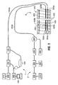
- Figure 1 shows a first embodiment, in which the interferometric sensor and the location sensor are located on the same optical fibre.
- Equipment related to the generation of the interferometric sensor beam and for reading signals received by the interferometic sensor is indicated generally at 1, and such equipment has reference numerals between 100 and 199.
- Equipment related to the location sensor is indicated generally at 2, and such equipment has reference numerals between 200 and 299.
- Equipment common to both, and the sensing portion, is indicated generally at 3.
- Other things present, such as the environment being sensed, are indicated by reference numerals higher than 400.
- the portion of the apparatus which forms the interferometric sensor beam will first be described.
- the interferometric sensor exemplified is a known Sagnac type interferometer.
- the particular Sagnac-type interferometer used in the example herein was constructed by Pure Technologies Ltd., of 705 11 th Ave. S.W., Calgary AB, Canada. Sagnac-type interferometers are available commercially from Blue Road Research, 219 NE 219 th Avenue, Greshem, Ore, U.S.A.
- a Michelson interferometric sensor can be used. This can also be obtained commercially from Blue Road Research, of which the address is given above.
- a source of coherent light (a laser) 100 and suitable control circuitry 110 for it are provided.
- the laser is chosen to give coherent light at a wavelength of approximately 1310 nm.
- this wavelength can be selected in known manner according to the particular type of fibre to be used, and expected sources of interference, so as to minimize probable interference and to maximize the signal from any expected disturbance which is sought to be monitored.
- the laser signal is sent through a suitable optical fibre 120 to a coupler 130.
- the coupler 130 splits the laser output into two parts, which pass over optical fibres 121 and 122.
- Fibre122 leads to a modulator 140, which modulates laser light passing through it..
- the modulated light is then sent through a delay coil 150, and is then sent back by line 123 to a coupler 160, the modulated light coming along branch 123 and the unmodulated light from fibre 121 go together out of the coupler 160 on fibre 124 . They pass through a short pass filter 170, which has the function of screening out wavelengths longer than the wavelength of the laser 100.
- the filter screens out wavelengths longer than 1310 nm., with the screening becoming more effective as the wavelength gets longer.
- This filter is used to eliminate extraneous wavelengths from the returning laser signals going to the receiver. From the filter 170, fibre 125 leads to a combining coupler.
- the apparatus is a Phase-OTDR sensor, as described in Taylor (SPIE, 2003).
- SPIE Phase-OTDR sensor
- Any other laser sensor which is capable of sensing a disturbance of the type being monitored and its location could be used, such as a Brillouin based system available as a Ditest Model BOTR from Smartec SA located at Via Probette 11, CH6928 Manno, Switzerland.
- the location sensor exemplified has a laser 200, suitably controlled by controls 210.
- the coherent light from the laser is at a longer wavelength than the light from laser 100. In the example, the wavelength is 1550 nm.
- the light passes through optical fibre 220 to a pulser 230, which is controlled by suitable controls 235. If desired, fibre 220 can contain an attenuator (not numbered) as Known in the art.
- Pulser 230 causes the coherent light from the laser to be sent out in pulses, at a desired repetition rate. The pulses are spaced sufficiently so that the light can travel to the end of the sensor and back before the next pulse is sent out.
- a pulse can be of the order of 20 to 1000 nanoseconds in length, and the repetition (refresh) rate should be at least 10 times a second, depending on the length of the sensor. Preferred rates are higher than this, being about 500 to 5000 kH.
- the sampling rate of the returning waveform will be chosen so as to get a spatial resolution of 0.2 km or less (i.e. an event seen can be located to within 200 metres). Preferably, it will be chosen to get an even smaller spatial resolution.
- Pulsed lasers are well known in the art, and a suitable pulse length, repetition rate, and sampling rate for the particular length and composition of the sensor being used can be chosen by a person skilled in the art.
- the propagation of the disturbance in both directions from the source offers the chance to greatly improve the accuracy of the location estimate, by using the expected symmetrical propagation pattern over many Phase-OTDR traces to more accurately measure the position of the origin of the disturbance, and to eliminate from consideration the portions of the trace that result from other noises in the pipeline.
- spatial resolution which is not as good as 200 metres can be tolerated, because the symmetrical phase - OTDR pattern can be used to improve the accuracy.
- the pulsed light passes along fibre 221 and preferably through an amplifier 240 out from it along fibre 222. If the amplifier is not present, fibre 222 is merely a continuation of fibre 221.
- the light then passes into a circulator 250.
- a circulator 250 This is known in the art of fibre optic components.
- Two other fibres, 223 and 224 also enter the circulator.
- Fibre 223 goes to a receiver 260, and fibre 224 goes to a long pass filter 270.
- the circulator permits light to pass from fibre 222 to fibre 224, or from fibre 224 to fibre 223.
- the long pass filter 270 screens out light which has a shorter wavelength than the light from coherent light source 200.
- the long pass filter would screen out light with a wavelength shorter than 1550 nm., with the screening becoming more pronounced the shorter the wavelength becomes.
- fibres 120, 121, 122, 123, 124, 125, 220, 221, 222, 223, 224,225, and 310, and 336 and 227 are preferably suitably shielded to minimize ambient noise so as to reduce interference in the sensor systems. Shielding may be by physical separation, or by the use of materials that will block disturbances, as is well known in the art.
- Fibre 310 is attached to detector fibre 320.
- Fibre 320 is not shielded, so is capable of having perturbations created in the light within it by an external disturbance.
- detector fibre 320 may be quite long, for example up to 20 km. or more. To indicate that the full length of the detector fibre is not shown, two parallel lines 400 have been drawn across the sensor fibre. These do not indicate an interruption in the fibre, but merely that the fibre extends a long distance, and a portion of it has been omitted. Fibre 320 terminates at the terminator 330.
- the terminator has two parts. One is a "mirror" that reflects the 1310 nm light back. The other minimizes the reflections of the 1550 nm light. These are the normal functions of the terminator for an interferometric sensor and a phased - OTDR sensor respectively.
- Filter 270 excludes the light from the interferometric sensor, as that light has a wavelength of 1310 nm, and cannot pass through the filter 270.
- Filter 170 excludes light from the pulsed laser as that light has a wavelength of approximately 1550 nm, which cannot pass through filter 170.
- the receiver-analyzer-demodulator also receives the modulating signal over fibre 127, so that it can have access to the interference of the counterpropagating light beams.
- the receiver and analyzer use the interferometric pattern of the light in conventional fashion to create a digital or analog output indicative of disturbances that have occurred along the fibre.
- An operator console 190 permits an operator to see the signal and to direct further operations, such as a Fourier transform or other analysis, on it.
- the light that passes through filter 270 goes to receiver 260, which produces an output which relates to the amplitude of the light and the elapsed time, from the start of the pulse. This is conveniently output as a three-dimensional plot, with a lapsed time recorded from successive pulses, the delay time for the OTDR reflections, and the amplitude.
- the sensor 320 is shown schematically as resting along the bottom of a concrete pipe generally indicated at 410.
- the concrete pipe has a wall 420, in which are contained prestressing wires 430. Only a few such wires are shown in the drawing, but it is understood that such wires would be tightly wrapped around the pipe to keep it compressed.
- a wire 431 is broken at 432.
- acoustic waves and seismic waves (both generally shown as 433) expand outward from the break.
- the waves may be transmitted through the medium of the concrete pipe, or through the concrete pipe and through the fluid medium that it contains. These waves first impinge on the sensor at a point 450. Subsequently, waves also impinge on the sensor at locations extending in both directions from point 450, as subsequent parts of the acoustic and seismic wavefronts hit the sensor 320.
- each receiver 180 and 260 receives substantially only the light generated by its associated laser, thus making analysis of disturbance of the light reacting to a disturbance in the fibre easier.
- FIG. 2 shows an alternate form of the system. Similar numbers are used for similar parts.
- Figures 1 and 2 The difference between Figures 1 and 2 is that the interferometric sensing laser and the position sensing laser are not connected to the same sensor. Instead, there is a sensor 320a for the interferometric sensor, and a sensor 320b for the position sensing laser. Each also has a separate terminator, numbered 330a and 330b respectively. For the terminator 330a, a mirror is used. For the terminator 330b, a non-reflecting terminator known in the art is used. Also, the filters 170 and 270 and the coupler 300 are not necessary, because the light from the two lasers is not sent through the same fibre. Indeed, it is no longer necessary to use different wavelengths of light. For example, in the Figure 2 embodiment, both laser 100 and laser 200 could use light of 1550 nm if desired.
- the system of Figure 2 is preferred, because if there is a problem with one of the sensors, it can be removed and replaced without disturbing the other sensor (provided that the two sensors are not in the same cable). Also, it permits an optimal wavelength to be chosen for each sensor, without worry about having to have a sufficient separation between wavelengths to prevent overlap in signals.
- the two sensors 320a and 320b must be adjacent to one another, so that each receives a signal from an event of interest, such as a wire break or a noise made by an intruder at substantially the same time. This is necessary so that the location can be determined with precision using the location determining system once the event of interest has been determined, using the interferometric system.
- an event of interest such as a wire break or a noise made by an intruder
- the distance between the two sensors can be varied according to the installation. Generally, however, it is preferred that the two fibre optic fibres 320a and 320b be adjacent to each other, as for example within a single cable which contains multiple fibres. In any event, it is preferred that there not be a separation of more than about 50 centimeters between the two fibres, and preferably not more than 10 centimeters.
- Test facility was set up as Figure 2 .
- Sensor 320a had a sensor length of 10 kilometers, and was laid in a disused concrete water pipe.
- Sensors 320b and sensor 320a were two individual fibres within a single fibre optic cable, and were of the same length.
- the interferometric sensor had a wavelength of 1310 nm.
- the pulsed OTDR sensor had a wavelength of 1550 nm, and was set to scan the length of the optical fibre every 10 milliseconds. Each scan took 200 microseconds. At least 750 scans of the OTDR were retained in memory. As each new scan was added, the oldest scan was dropped.
- an event of interest would be any event that gave an analog signal of greater than 5 volts on an analog output in the particular test facility.
- the analog output was an arbitrary representation of disturbances in the interferometric pattern in the Sagnac interferometric laser.
- An initial test showed that the cutting of a wire reinforcement in a concrete pipe gave a signal of 10 volts or more. As the test was to see if wire breaks could be detected, it was decided that the threshold for an event of interest would be set at approximately half that level, or 5 volts.
- Figure 3 shows, as an analog signal output of volts relative to time, the output of the interferometric sensor as recovered at receiver 180. Deviations from the central line represent a phase shift in the returning light.
- the time is arbitrary, from a base 0 which is common to both sensor outputs.
- the interferometer gives essentially a flat signal 600 (no phase shift between the light sent out and the light received), until approximately 30 milliseconds on the arbitrary scale. Then, it gives a large response 610. The response decays rapidly, but there are still more perturbations in the signal than there were prior to the event which occurred at 30 milliseconds. At approximately 126 milliseconds on the arbitrary scale, a further event 620 that perturbs the light occurs.
- the event which triggered at approximately 30 milliseconds is greater than 5 volts on the arbitrary scale, and is therefore an event of interest. Therefore, the position locating laser output (OTDR output) for at least 30 milliseconds (150 sweeps) prior to the beginning of the apparent event of interest are saved, as are at least 600 subsequent sweeps.
- ODR output position locating laser output
- the operator can then decide to do a Fourier transform of the signal from the interferometer from the time just before during and after that event.
- a Fourier transform is shown in Figure 4 .
- the Fourier Transform confirms that the event is indicative of a wire break, which is an event of interest when monitoring a concrete pipe having wire wrapping.
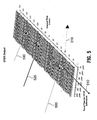
- Figure 5 is a graph of the output of the OTDR location sensor.
- the graph is in three dimensions.
- the scale on the right shows the elapsed time in milliseconds.
- the scale on the left shows the scan times for the OTDR.
- Each line across the graph parallel to the scale is the trace of one scan. It will be remembered that in this example the scans repeat every 200 microseconds,
- the vertical axis (showing peaks) is an arbitrary scale showing deviations from the ordinary background noise. Conveniently, this scale can be expressed in volts, but the magnitude is not of interest in the particular application, except to determine that the event has passed the arbitrary minimum defined to be an event of interest. Instead, only the time on the arbitrary millisecond scale is of interest.
- the perturbation is noted when the ODTR pulse had passed down the fibre for 87 microseconds. It is known that the particular fibre transmits light of this wavelength at 9.73 microseconds/km. Thus, the location of the perturbation corresponds to a position of 87/9.73 km, which is 8.94 kilometers, from the beginning of the sensor 320a and 320b.
- the location at 8.94 km down the sensors, in the concrete water pipe, is examined, and is found to correspond to a location where an induced wire breakage has been done during the test.
- a Fourier transform of this signal could be done to see whether a characteristic signature of an event of interest could be noted.
- the event referenced by the numerals at 530 and 620 is not of sufficient interest (because of the relatively small interferometric output) for further consideration.
- the event at 520 on the OTDR output does not have a corresponding event in the interferometric output. It happens frequently that there is a signal on one or other of the OTDR or interferometric signals, but no corresponding output on the other one. In such a case case, the signal is regarded as noise and is ignored, because it has not been confirmed by a signal on the other sensor.
Landscapes
- Physics & Mathematics (AREA)
- General Physics & Mathematics (AREA)
- Chemical & Material Sciences (AREA)
- Analytical Chemistry (AREA)
- Optical Transform (AREA)
- Length Measuring Devices By Optical Means (AREA)
- Measurement Of Mechanical Vibrations Or Ultrasonic Waves (AREA)
Claims (9)
- Faseroptik-Überwachungssystem zum Detektieren und Lokalisieren von Störungen entlang eines vorbestimmten Wegs, umfassend:einen ersten Faseroptik-Sensor (1), welcher eine optische Faser (320; 320a) umfasst, welche sich entlang des vorbestimmten Wegs erstreckt und welche kontinuierlich Störungen entlang des gesamten vorbestimmten Wegs detektiert und eine erste Ausgabe erzeugt, wobei der erste Faseroptik-Sensor (1) ein Interferometrie-Sensor ist;einen zweiten Faseroptik-Sensor (2), welcher eine optische Faser (320; 320b) umfasst, welche sich entlang des vorbestimmten Wegs erstreckt und welche eine zweite Ausgabe erzeugt, welche Störungen und ihre Positionen entlang des vorbestimmten Wegs detektiert;Mittel (190) zum Analysieren der Ausgabe des ersten Faseroptik-Sensors;Mittel (260) zum Analysieren der Ausgabe des zweiten Faseroptik-Sensors;dadurch gekennzeichnet, dassdie optische Faser (320, 320a) des ersten Faseroptik-Sensors (1) und die optische Faser (320, 320b) des zweiten Faseroptik-Sensors (2) separate optische Fasern (320a, 320b) sind, welche benachbart zu einander angeordnet sind, oder eine gemeinsame optische Faser (320) des ersten (1) und zweiten (2) Faseroptik-Sensors sind;die Mittel (190) zum Analysieren der Ausgabe des ersten Faseroptik-Sensors (1) dazu eingerichtet sind, von ihm sensierte Störungen zu identifizieren, welche wenigstens eine vorbestimmte Charakteristik aufweisen, unddie Mittel (260) zum Analysieren der Ausgabe des zweiten Faseroptik-Sensors dazu eingerichtet sind, zu bestimmen, ob eine entsprechende Störung zu einer dem Sensieren einer Störung durch den ersten Faseroptik-Sensor (1) mit der einen vorbestimmten Charakteristik in etwa entsprechenden Zeit sensiert worden ist, und wenn dies der Fall ist, die Position der entsprechenden Störung entlang des vorbestimmten Wegs zu bestimmen.
- Vorrichtung nach Anspruch 1, dadurch gekennzeichnet, dass der erste Faseroptik-Sensor (1) ein Sagnac-Effekt-Sensor ist.
- Vorrichtung nach Anspruch 1, dadurch gekennzeichnet, dass der erste Faseroptik-Sensor (1) ein Michelson-Sensor ist.
- Vorrichtung nach einem der Ansprüche 1 bis 3, dadurch gekennzeichnet, dass der zweite Faseroptik-Sensor (2) ein Phasen-OTDR-Sensor ist.
- Vorrichtung nach einem der Ansprüche 1 bis 3, dadurch gekennzeichnet, dass der zweite Faseroptik-Sensor (2) ein Brillouin-Effekt-Sensor ist.
- Verfahren zum Lokalisieren von Störungen entlang eines Faseroptik-Detektorsystems einer vorbestimmten Länge, umfassend:kontinuierliches Sensieren von Störungen entlang des vorbestimmten Wegs mit einem ersten Faseroptik-Sensor (1), umfassend eine optische Faser, und Erzeugen eines ersten Ausgabe-Signals von dem ersten Faseroptik-Sensor (1) wenn Störungen detektiert werden, wobei der erste Faseroptik-Sensor (1) ein Interferometrie-Sensor ist;Analysieren des Ausgabe-Signals zum Bestimmen, ob es wenigstens eine vorbestimmte Charakteristik aufweist,gleichzeitiges Sensieren von Störungen unter Verwendung eines zweiten Faseroptik-Sensors (2), umfassend eine optische Faser, welche sich entlang des vorbestimmten Wegs erstreckt, und welcher eine zweite Ausgabe erzeugt, welcher Störungen und ihre Positionen entlang dem vorbestimmten Weg detektiert,dadurch gekennzeichnet, dassdie optische Faser (320, 320a) des ersten Faseroptik-Sensors (1) und die optische Faser (320, 320b) des zweiten Faseroptik-Sensors (2) separate optische Fasern (320a, 320b) sind, welche benachbart zu einander angeordnet sind, oder eine gemeinsame optische Faser (320) des ersten (1) und zweiten (2) Faseroptik-Sensors sind; undwenn eine Störung von dem ersten Faseroptik-Sensor (1) gefunden wird, welche eine solche vorbestimmte Charakteristik aufweist, dann die Ausgabe des zweiten Faseroptik-Sensors (2) analysiert wird, um zu bestimmen, ob eine entsprechende Störung zu einer dem Sensieren der Störung durch den ersten Faseroptik-Sensor (1) mit der einen vorbestimmten Charakteristik in etwa entsprechenden Zeit sensiert worden ist, und wenn dies der Fall ist, Bestimmen der Position einer entsprechenden Störung entlang des vorbestimmten Wegs.
- Verfahren nach Anspruch 6, dadurch gekennzeichnet, dass der ersten Faseroptik-Sensor (1) ein Sagnac-Effekt-Sensor ist, und der zweite Faseroptik-Sensor (2) ein Phasen-OTDR-Sensor ist.
- Verfahren nach Anspruch 6 oder 7, dadurch gekennzeichnet, dass die eine vorbestimmte Charakteristik ist, dass die Störung ein Signal von dem ersten Faseroptik-Sensor (1) hervorruft, welches Signal mehr als eine vorbestimmte Spitzen-Energie aufweist.
- Verfahren nach Anspruch 6 oder 7, dadurch gekennzeichnet, dass die eine vorbestimmte Charakteristik ist, dass die Störung ein Signal von dem ersten Faseroptik-Sensor (1) hervorruft, welches Signal eine räumliche Verteilung aufweist, welche als von Interesse vorbestimmt ist.
Applications Claiming Priority (2)
| Application Number | Priority Date | Filing Date | Title |
|---|---|---|---|
| CA002467898A CA2467898A1 (en) | 2004-05-21 | 2004-05-21 | Fiber optic sensor method and apparatus |
| PCT/CA2005/000784 WO2005114226A1 (en) | 2004-05-21 | 2005-05-24 | Fibre optic sensor method and apparatus |
Publications (3)
| Publication Number | Publication Date |
|---|---|
| EP1747472A1 EP1747472A1 (de) | 2007-01-31 |
| EP1747472A4 EP1747472A4 (de) | 2007-12-12 |
| EP1747472B1 true EP1747472B1 (de) | 2014-06-18 |
Family
ID=35428493
Family Applications (1)
| Application Number | Title | Priority Date | Filing Date |
|---|---|---|---|
| EP05748527.8A Expired - Lifetime EP1747472B1 (de) | 2004-05-21 | 2005-05-24 | Faseroptisches sensorverfahren und vorrichtung |
Country Status (6)
| Country | Link |
|---|---|
| US (1) | US7564540B2 (de) |
| EP (1) | EP1747472B1 (de) |
| CA (2) | CA2467898A1 (de) |
| ES (1) | ES2498815T3 (de) |
| PT (1) | PT1747472E (de) |
| WO (1) | WO2005114226A1 (de) |
Cited By (2)
| Publication number | Priority date | Publication date | Assignee | Title |
|---|---|---|---|---|
| CN104964699A (zh) * | 2015-05-22 | 2015-10-07 | 北京交通大学 | 基于φ-OTDR光纤分布式扰动传感器的扰动判断方法和装置 |
| CN110057387A (zh) * | 2019-05-10 | 2019-07-26 | 南昌航空大学 | 直线型Sagnac分布式光纤传感系统的定位方法 |
Families Citing this family (70)
| Publication number | Priority date | Publication date | Assignee | Title |
|---|---|---|---|---|
| US7994912B2 (en) * | 2006-01-12 | 2011-08-09 | Mitsubishi Electric Corporation | Intrusion-object detection system, method of detecting intrusion-object and method of detecting malfunction |
| US7366055B2 (en) * | 2006-05-05 | 2008-04-29 | Optoplan As | Ocean bottom seismic sensing system |
| US8064286B2 (en) * | 2006-05-05 | 2011-11-22 | Optoplan As | Seismic streamer array |
| DE102006023588B3 (de) * | 2006-05-17 | 2007-09-27 | Sächsisches Textilforschungsinstitut eV | Verwendung eines multifunktionalen, sensorbasierten Geotextilsystems zur Deichertüchtigung, für räumlich ausgedehntes Deichmonitoring sowie für die Gefahrenerkennung im Hochwasserfall |
| CN100422629C (zh) * | 2006-09-08 | 2008-10-01 | 北京工业大学 | 基于Sagnac光纤干涉仪的管道泄漏监测装置 |
| CN101251950B (zh) * | 2008-04-03 | 2010-06-02 | 东南大学 | 宽域全光纤扰动传感网络系统限定式扰动信号处理识别装置 |
| WO2011046463A1 (en) * | 2009-10-15 | 2011-04-21 | Siemens Aktiengesellschaft | Fluid pipe and method for detecting a deformation on the fluid pipe |
| CA3177996A1 (en) | 2010-06-16 | 2011-12-22 | Mueller International, Llc | Infrastructure monitoring devices, systems, and methods |
| KR101522318B1 (ko) * | 2010-10-14 | 2015-05-27 | 파이버소닉스 인크. | 간섭계 시스템 |
| WO2012135103A2 (en) * | 2011-03-25 | 2012-10-04 | Ohio University | Security system for underground conduit |
| US9772250B2 (en) | 2011-08-12 | 2017-09-26 | Mueller International, Llc | Leak detector and sensor |
| CN102589578B (zh) * | 2012-03-07 | 2014-09-24 | 杭州安远科技有限公司 | 基于相位解调的分布式光纤传感装置及方法 |
| CA2875324C (en) * | 2012-06-12 | 2020-04-28 | Eolis Medi@ Company | Currentless optical switch |
| CA2889284C (en) | 2012-10-26 | 2020-09-15 | Mueller International, Llc | Detecting leaks in a fluid distribution system |
| US20150355107A1 (en) * | 2012-12-28 | 2015-12-10 | Pure Technologies Ltd. | Tethered sensing system for pipelines |
| CA2845350C (en) | 2013-03-22 | 2018-12-18 | Syscor Controls & Automation Inc. | Cable assembly for providing power through inductive coupling |
| EP3126808A1 (de) | 2014-04-04 | 2017-02-08 | Exxonmobil Upstream Research Company | Echtzeitüberwachung einer metalloberfläche |
| GB2525251A (en) * | 2014-04-18 | 2015-10-21 | Mic Ag | Optical fibre sensor system |
| CN104236697B (zh) * | 2014-09-01 | 2017-02-15 | 中国石油天然气股份有限公司 | 一种基于波分复用的分布式光纤振动检测方法及系统 |
| US9528903B2 (en) | 2014-10-01 | 2016-12-27 | Mueller International, Llc | Piezoelectric vibration sensor for fluid leak detection |
| US9928705B2 (en) | 2015-06-16 | 2018-03-27 | Utc Fire & Security Corporation | Threat detection system |
| CN104966076A (zh) * | 2015-07-21 | 2015-10-07 | 北方工业大学 | 基于支持向量机的光纤入侵信号分类识别方法 |
| CN105096490B (zh) * | 2015-09-02 | 2020-12-25 | 同方威视技术股份有限公司 | 分布式光纤周界安防系统、声音还原系统及方法 |
| US10305178B2 (en) | 2016-02-12 | 2019-05-28 | Mueller International, Llc | Nozzle cap multi-band antenna assembly |
| US10283857B2 (en) | 2016-02-12 | 2019-05-07 | Mueller International, Llc | Nozzle cap multi-band antenna assembly |
| BR112018070565A2 (pt) | 2016-04-07 | 2019-02-12 | Bp Exploration Operating Company Limited | detecção de eventos de fundo de poço usando características de domínio da frequência acústicas |
| EP3440313B1 (de) | 2016-04-07 | 2020-03-04 | BP Exploration Operating Company Limited | Erkennung von bohrlochereignissen mit akustischen frequenzbereichsmerkmalen |
| GB201700984D0 (en) * | 2017-01-20 | 2017-03-08 | Smart Fibres Ltd | Apparatus and method for locating a measurand anomaly along a waveguide |
| BR112019020125B1 (pt) | 2017-03-31 | 2023-09-26 | Bp Exploration Operating Company Limited | Métodos e sistemas para detectar vazamentos em um furo de poço |
| WO2019038401A1 (en) | 2017-08-23 | 2019-02-28 | Bp Exploration Operating Company Limited | DETECTION OF SAND INPUT LOCATIONS AT THE BOTTOM OF A HOLE |
| JP7277059B2 (ja) | 2017-10-11 | 2023-05-18 | ビーピー エクスプロレーション オペレーティング カンパニー リミテッド | 音響周波数領域特徴を使用した事象の検出 |
| US10859462B2 (en) | 2018-09-04 | 2020-12-08 | Mueller International, Llc | Hydrant cap leak detector with oriented sensor |
| US11519779B1 (en) * | 2018-09-12 | 2022-12-06 | Innoveering, LLC | Evanescent field coupled shock wave detection systems and methods |
| US12571301B2 (en) | 2018-11-29 | 2026-03-10 | Bp Exploration Operating Company Limited | DAS data processing to identify fluid inflow locations and fluid type |
| GB201820331D0 (en) * | 2018-12-13 | 2019-01-30 | Bp Exploration Operating Co Ltd | Distributed acoustic sensing autocalibration |
| US11342656B2 (en) | 2018-12-28 | 2022-05-24 | Mueller International, Llc | Nozzle cap encapsulated antenna system |
| US11473993B2 (en) | 2019-05-31 | 2022-10-18 | Mueller International, Llc | Hydrant nozzle cap |
| CN110160627A (zh) * | 2019-05-31 | 2019-08-23 | 太原理工大学 | 迈克尔逊干涉与相位敏感光时域反射的光纤声音传感系统 |
| CN114127519A (zh) * | 2019-07-16 | 2022-03-01 | 日本电气株式会社 | 光纤感测系统、光纤感测装置和用于检测管道劣化的方法 |
| CN110517460A (zh) * | 2019-08-29 | 2019-11-29 | 三峡大学 | 一种高拱坝混凝土温度状态区间预测预警方法 |
| WO2021052602A1 (en) | 2019-09-20 | 2021-03-25 | Lytt Limited | Systems and methods for sand ingress prediction for subterranean wellbores |
| CA3154435C (en) | 2019-10-17 | 2023-03-28 | Lytt Limited | Inflow detection using dts features |
| EP4045766A1 (de) | 2019-10-17 | 2022-08-24 | Lytt Limited | Flüssigkeitszuflusscharakterisierung unter verwendung von hybriden das/dts-messungen |
| WO2021093974A1 (en) | 2019-11-15 | 2021-05-20 | Lytt Limited | Systems and methods for draw down improvements across wellbores |
| CA3103413C (en) | 2019-12-30 | 2023-04-25 | Marathon Petroleum Company Lp | Methods and systems for inline mixing of hydrocarbon liquids based on density or gravity |
| CA3104319C (en) | 2019-12-30 | 2023-01-24 | Marathon Petroleum Company Lp | Methods and systems for spillback control of in-line mixing of hydrocarbon liquids |
| US11607654B2 (en) | 2019-12-30 | 2023-03-21 | Marathon Petroleum Company Lp | Methods and systems for in-line mixing of hydrocarbon liquids |
| US11542690B2 (en) | 2020-05-14 | 2023-01-03 | Mueller International, Llc | Hydrant nozzle cap adapter |
| CA3180595A1 (en) | 2020-06-11 | 2021-12-16 | Lytt Limited | Systems and methods for subterranean fluid flow characterization |
| WO2021254633A1 (en) | 2020-06-18 | 2021-12-23 | Lytt Limited | Event model training using in situ data |
| CA3182376A1 (en) | 2020-06-18 | 2021-12-23 | Cagri CERRAHOGLU | Event model training using in situ data |
| WO2022066060A1 (ru) * | 2020-09-28 | 2022-03-31 | Акционерное Общество "Институт "Оргэнергострой" | Ограждение с линейной частью извещателя охранного волоконно-оптического |
| CN113031470A (zh) * | 2020-12-31 | 2021-06-25 | 安徽中科昊音智能科技有限公司 | Pccp钢丝断丝监控系统 |
| US12012883B2 (en) | 2021-03-16 | 2024-06-18 | Marathon Petroleum Company Lp | Systems and methods for backhaul transportation of liquefied gas and CO2 using liquefied gas carriers |
| US11578836B2 (en) | 2021-03-16 | 2023-02-14 | Marathon Petroleum Company Lp | Scalable greenhouse gas capture systems and methods |
| US11655940B2 (en) | 2021-03-16 | 2023-05-23 | Marathon Petroleum Company Lp | Systems and methods for transporting fuel and carbon dioxide in a dual fluid vessel |
| US11578638B2 (en) | 2021-03-16 | 2023-02-14 | Marathon Petroleum Company Lp | Scalable greenhouse gas capture systems and methods |
| CN112880929B (zh) * | 2021-04-07 | 2022-09-13 | 西北工业大学 | 一种航空复杂管路气密性的快速自动检测方法 |
| US12043905B2 (en) | 2021-08-26 | 2024-07-23 | Marathon Petroleum Company Lp | Electrode watering assemblies and methods for maintaining cathodic monitoring of structures |
| US12180597B2 (en) | 2021-08-26 | 2024-12-31 | Marathon Petroleum Company Lp | Test station assemblies for monitoring cathodic protection of structures and related methods |
| US12129559B2 (en) | 2021-08-26 | 2024-10-29 | Marathon Petroleum Company Lp | Test station assemblies for monitoring cathodic protection of structures and related methods |
| US11447877B1 (en) | 2021-08-26 | 2022-09-20 | Marathon Petroleum Company Lp | Assemblies and methods for monitoring cathodic protection of structures |
| US11686070B1 (en) | 2022-05-04 | 2023-06-27 | Marathon Petroleum Company Lp | Systems, methods, and controllers to enhance heavy equipment warning |
| US12578245B2 (en) | 2022-10-28 | 2026-03-17 | Mueller International, Llc | Self-leveling sensor assembly |
| US12012082B1 (en) | 2022-12-30 | 2024-06-18 | Marathon Petroleum Company Lp | Systems and methods for a hydraulic vent interlock |
| US12043361B1 (en) | 2023-02-18 | 2024-07-23 | Marathon Petroleum Company Lp | Exhaust handling systems for marine vessels and related methods |
| US12006014B1 (en) | 2023-02-18 | 2024-06-11 | Marathon Petroleum Company Lp | Exhaust vent hoods for marine vessels and related methods |
| CN116429785B (zh) * | 2023-04-19 | 2025-09-26 | 南京大学 | 一种基于分布式光纤传感的pccp断丝监测系统及方法 |
| US12297965B2 (en) | 2023-08-09 | 2025-05-13 | Marathon Petroleum Company Lp | Systems and methods for mixing hydrogen with natural gas |
| US12087002B1 (en) | 2023-09-18 | 2024-09-10 | Marathon Petroleum Company Lp | Systems and methods to determine depth of soil coverage along a right-of-way |
Family Cites Families (4)
| Publication number | Priority date | Publication date | Assignee | Title |
|---|---|---|---|---|
| US5355208A (en) | 1992-06-24 | 1994-10-11 | Mason & Hanger National, Inc. | Distributed fiber optic sensor for locating and identifying remote disturbances |
| US5798457A (en) | 1993-06-25 | 1998-08-25 | Pure Technologies Inc. | Continuous monitoring of reinforcements in structures |
| GB9700269D0 (en) * | 1997-01-08 | 1997-02-26 | York Sensors Ltd | Improvements to optical time domain reflectometry |
| WO2000037925A1 (en) * | 1998-12-18 | 2000-06-29 | Future Fibre Technologies Pty Ltd | Apparatus and method for monitoring a structure using a counter-propagating signal method for locating events |
-
2004
- 2004-05-21 CA CA002467898A patent/CA2467898A1/en not_active Abandoned
-
2005
- 2005-05-24 EP EP05748527.8A patent/EP1747472B1/de not_active Expired - Lifetime
- 2005-05-24 US US11/569,419 patent/US7564540B2/en not_active Expired - Lifetime
- 2005-05-24 WO PCT/CA2005/000784 patent/WO2005114226A1/en not_active Ceased
- 2005-05-24 PT PT57485278T patent/PT1747472E/pt unknown
- 2005-05-24 ES ES05748527.8T patent/ES2498815T3/es not_active Expired - Lifetime
- 2005-05-24 CA CA2567551A patent/CA2567551C/en not_active Expired - Lifetime
Cited By (3)
| Publication number | Priority date | Publication date | Assignee | Title |
|---|---|---|---|---|
| CN104964699A (zh) * | 2015-05-22 | 2015-10-07 | 北京交通大学 | 基于φ-OTDR光纤分布式扰动传感器的扰动判断方法和装置 |
| CN110057387A (zh) * | 2019-05-10 | 2019-07-26 | 南昌航空大学 | 直线型Sagnac分布式光纤传感系统的定位方法 |
| CN110057387B (zh) * | 2019-05-10 | 2021-01-19 | 南昌航空大学 | 直线型Sagnac分布式光纤传感系统的定位方法 |
Also Published As
| Publication number | Publication date |
|---|---|
| EP1747472A1 (de) | 2007-01-31 |
| US20070247631A1 (en) | 2007-10-25 |
| EP1747472A4 (de) | 2007-12-12 |
| US7564540B2 (en) | 2009-07-21 |
| CA2567551C (en) | 2013-07-02 |
| WO2005114226A1 (en) | 2005-12-01 |
| ES2498815T3 (es) | 2014-09-25 |
| CA2467898A1 (en) | 2005-11-21 |
| HK1100231A1 (en) | 2007-09-14 |
| CA2567551A1 (en) | 2005-12-01 |
| PT1747472E (pt) | 2014-09-03 |
Similar Documents
| Publication | Publication Date | Title |
|---|---|---|
| EP1747472B1 (de) | Faseroptisches sensorverfahren und vorrichtung | |
| RU2518978C2 (ru) | Волоконно-оптическое акустическое измерение | |
| RU2446476C2 (ru) | Отказоустойчивое распределенное оптоволоконное обнаружение проникновения | |
| US9599272B2 (en) | Monitoring of the position of a pipe inspection tool in a pipeline | |
| US9759824B2 (en) | Seismic monitoring | |
| CN102292621B (zh) | 分布式光纤感测中的改进 | |
| EP2817604B1 (de) | Überwachung einer transportnetzwerkinfrastruktur | |
| US5705984A (en) | Passive intrusion detection system | |
| JP2019518968A (ja) | 光ファイバセンシング | |
| EP3254069A1 (de) | Glasfasersensorik | |
| JP4526537B2 (ja) | 光ファイバ監視システム | |
| Zhong et al. | Nuisance alarm rate reduction using pulse-width multiplexing Φ-OTDR with optimized positioning accuracy | |
| HK1100231B (en) | Fibre optic sensor method and apparatus | |
| WO2022159906A1 (en) | Detection of static weight on aerial telecommunications optical fibers using das ambient data | |
| CA2969058C (en) | Optical fibre sensing | |
| CN113295259A (zh) | 一种分布式光纤传感系统 |
Legal Events
| Date | Code | Title | Description |
|---|---|---|---|
| PUAI | Public reference made under article 153(3) epc to a published international application that has entered the european phase |
Free format text: ORIGINAL CODE: 0009012 |
|
| 17P | Request for examination filed |
Effective date: 20061121 |
|
| AK | Designated contracting states |
Kind code of ref document: A1 Designated state(s): AT BE BG CH CY CZ DE DK EE ES FI FR GB GR HU IE IS IT LI LT LU MC NL PL PT RO SE SI SK TR |
|
| AX | Request for extension of the european patent |
Extension state: AL BA HR LV MK YU |
|
| REG | Reference to a national code |
Ref country code: HK Ref legal event code: DE Ref document number: 1100231 Country of ref document: HK |
|
| A4 | Supplementary search report drawn up and despatched |
Effective date: 20071109 |
|
| RAP1 | Party data changed (applicant data changed or rights of an application transferred) |
Owner name: PURE TECHNOLOGIES LTD. |
|
| 17Q | First examination report despatched |
Effective date: 20130625 |
|
| GRAP | Despatch of communication of intention to grant a patent |
Free format text: ORIGINAL CODE: EPIDOSNIGR1 |
|
| INTG | Intention to grant announced |
Effective date: 20140107 |
|
| GRAS | Grant fee paid |
Free format text: ORIGINAL CODE: EPIDOSNIGR3 |
|
| GRAA | (expected) grant |
Free format text: ORIGINAL CODE: 0009210 |
|
| AK | Designated contracting states |
Kind code of ref document: B1 Designated state(s): AT BE BG CH CY CZ DE DK EE ES FI FR GB GR HU IE IS IT LI LT LU MC NL PL PT RO SE SI SK TR |
|
| AX | Request for extension of the european patent |
Extension state: AL BA HR LV MK YU |
|
| REG | Reference to a national code |
Ref country code: GB Ref legal event code: FG4D |
|
| REG | Reference to a national code |
Ref country code: CH Ref legal event code: EP |
|
| REG | Reference to a national code |
Ref country code: AT Ref legal event code: REF Ref document number: 673638 Country of ref document: AT Kind code of ref document: T Effective date: 20140715 |
|
| REG | Reference to a national code |
Ref country code: IE Ref legal event code: FG4D |
|
| REG | Reference to a national code |
Ref country code: DE Ref legal event code: R096 Ref document number: 602005043947 Country of ref document: DE Effective date: 20140731 |
|
| REG | Reference to a national code |
Ref country code: PT Ref legal event code: SC4A Free format text: AVAILABILITY OF NATIONAL TRANSLATION Effective date: 20140822 |
|
| REG | Reference to a national code |
Ref country code: ES Ref legal event code: FG2A Ref document number: 2498815 Country of ref document: ES Kind code of ref document: T3 Effective date: 20140925 |
|
| REG | Reference to a national code |
Ref country code: NL Ref legal event code: T3 |
|
| PG25 | Lapsed in a contracting state [announced via postgrant information from national office to epo] |
Ref country code: FI Free format text: LAPSE BECAUSE OF FAILURE TO SUBMIT A TRANSLATION OF THE DESCRIPTION OR TO PAY THE FEE WITHIN THE PRESCRIBED TIME-LIMIT Effective date: 20140618 Ref country code: LT Free format text: LAPSE BECAUSE OF FAILURE TO SUBMIT A TRANSLATION OF THE DESCRIPTION OR TO PAY THE FEE WITHIN THE PRESCRIBED TIME-LIMIT Effective date: 20140618 Ref country code: CY Free format text: LAPSE BECAUSE OF FAILURE TO SUBMIT A TRANSLATION OF THE DESCRIPTION OR TO PAY THE FEE WITHIN THE PRESCRIBED TIME-LIMIT Effective date: 20140618 |
|
| REG | Reference to a national code |
Ref country code: HK Ref legal event code: GR Ref document number: 1100231 Country of ref document: HK |
|
| REG | Reference to a national code |
Ref country code: AT Ref legal event code: MK05 Ref document number: 673638 Country of ref document: AT Kind code of ref document: T Effective date: 20140618 |
|
| REG | Reference to a national code |
Ref country code: LT Ref legal event code: MG4D |
|
| REG | Reference to a national code |
Ref country code: GR Ref legal event code: EP Ref document number: 20140401886 Country of ref document: GR Effective date: 20141017 |
|
| PG25 | Lapsed in a contracting state [announced via postgrant information from national office to epo] |
Ref country code: SE Free format text: LAPSE BECAUSE OF FAILURE TO SUBMIT A TRANSLATION OF THE DESCRIPTION OR TO PAY THE FEE WITHIN THE PRESCRIBED TIME-LIMIT Effective date: 20140618 |
|
| PG25 | Lapsed in a contracting state [announced via postgrant information from national office to epo] |
Ref country code: EE Free format text: LAPSE BECAUSE OF FAILURE TO SUBMIT A TRANSLATION OF THE DESCRIPTION OR TO PAY THE FEE WITHIN THE PRESCRIBED TIME-LIMIT Effective date: 20140618 Ref country code: RO Free format text: LAPSE BECAUSE OF FAILURE TO SUBMIT A TRANSLATION OF THE DESCRIPTION OR TO PAY THE FEE WITHIN THE PRESCRIBED TIME-LIMIT Effective date: 20140618 Ref country code: SK Free format text: LAPSE BECAUSE OF FAILURE TO SUBMIT A TRANSLATION OF THE DESCRIPTION OR TO PAY THE FEE WITHIN THE PRESCRIBED TIME-LIMIT Effective date: 20140618 Ref country code: CZ Free format text: LAPSE BECAUSE OF FAILURE TO SUBMIT A TRANSLATION OF THE DESCRIPTION OR TO PAY THE FEE WITHIN THE PRESCRIBED TIME-LIMIT Effective date: 20140618 |
|
| PG25 | Lapsed in a contracting state [announced via postgrant information from national office to epo] |
Ref country code: AT Free format text: LAPSE BECAUSE OF FAILURE TO SUBMIT A TRANSLATION OF THE DESCRIPTION OR TO PAY THE FEE WITHIN THE PRESCRIBED TIME-LIMIT Effective date: 20140618 Ref country code: PL Free format text: LAPSE BECAUSE OF FAILURE TO SUBMIT A TRANSLATION OF THE DESCRIPTION OR TO PAY THE FEE WITHIN THE PRESCRIBED TIME-LIMIT Effective date: 20140618 Ref country code: IS Free format text: LAPSE BECAUSE OF FAILURE TO SUBMIT A TRANSLATION OF THE DESCRIPTION OR TO PAY THE FEE WITHIN THE PRESCRIBED TIME-LIMIT Effective date: 20141018 |
|
| REG | Reference to a national code |
Ref country code: DE Ref legal event code: R097 Ref document number: 602005043947 Country of ref document: DE |
|
| PLBE | No opposition filed within time limit |
Free format text: ORIGINAL CODE: 0009261 |
|
| STAA | Information on the status of an ep patent application or granted ep patent |
Free format text: STATUS: NO OPPOSITION FILED WITHIN TIME LIMIT |
|
| PG25 | Lapsed in a contracting state [announced via postgrant information from national office to epo] |
Ref country code: IT Free format text: LAPSE BECAUSE OF FAILURE TO SUBMIT A TRANSLATION OF THE DESCRIPTION OR TO PAY THE FEE WITHIN THE PRESCRIBED TIME-LIMIT Effective date: 20140618 Ref country code: DK Free format text: LAPSE BECAUSE OF FAILURE TO SUBMIT A TRANSLATION OF THE DESCRIPTION OR TO PAY THE FEE WITHIN THE PRESCRIBED TIME-LIMIT Effective date: 20140618 |
|
| 26N | No opposition filed |
Effective date: 20150319 |
|
| REG | Reference to a national code |
Ref country code: DE Ref legal event code: R097 Ref document number: 602005043947 Country of ref document: DE Effective date: 20150319 |
|
| PG25 | Lapsed in a contracting state [announced via postgrant information from national office to epo] |
Ref country code: SI Free format text: LAPSE BECAUSE OF FAILURE TO SUBMIT A TRANSLATION OF THE DESCRIPTION OR TO PAY THE FEE WITHIN THE PRESCRIBED TIME-LIMIT Effective date: 20140618 |
|
| REG | Reference to a national code |
Ref country code: CH Ref legal event code: PL |
|
| PG25 | Lapsed in a contracting state [announced via postgrant information from national office to epo] |
Ref country code: CH Free format text: LAPSE BECAUSE OF NON-PAYMENT OF DUE FEES Effective date: 20150531 Ref country code: LU Free format text: LAPSE BECAUSE OF FAILURE TO SUBMIT A TRANSLATION OF THE DESCRIPTION OR TO PAY THE FEE WITHIN THE PRESCRIBED TIME-LIMIT Effective date: 20150524 Ref country code: MC Free format text: LAPSE BECAUSE OF FAILURE TO SUBMIT A TRANSLATION OF THE DESCRIPTION OR TO PAY THE FEE WITHIN THE PRESCRIBED TIME-LIMIT Effective date: 20140618 Ref country code: LI Free format text: LAPSE BECAUSE OF NON-PAYMENT OF DUE FEES Effective date: 20150531 |
|
| REG | Reference to a national code |
Ref country code: FR Ref legal event code: PLFP Year of fee payment: 12 |
|
| REG | Reference to a national code |
Ref country code: FR Ref legal event code: PLFP Year of fee payment: 13 |
|
| PG25 | Lapsed in a contracting state [announced via postgrant information from national office to epo] |
Ref country code: BG Free format text: LAPSE BECAUSE OF FAILURE TO SUBMIT A TRANSLATION OF THE DESCRIPTION OR TO PAY THE FEE WITHIN THE PRESCRIBED TIME-LIMIT Effective date: 20140618 Ref country code: HU Free format text: LAPSE BECAUSE OF FAILURE TO SUBMIT A TRANSLATION OF THE DESCRIPTION OR TO PAY THE FEE WITHIN THE PRESCRIBED TIME-LIMIT; INVALID AB INITIO Effective date: 20050524 |
|
| REG | Reference to a national code |
Ref country code: FR Ref legal event code: PLFP Year of fee payment: 14 |
|
| PGFP | Annual fee paid to national office [announced via postgrant information from national office to epo] |
Ref country code: NL Payment date: 20240526 Year of fee payment: 20 |
|
| PGFP | Annual fee paid to national office [announced via postgrant information from national office to epo] |
Ref country code: IE Payment date: 20240527 Year of fee payment: 20 |
|
| PGFP | Annual fee paid to national office [announced via postgrant information from national office to epo] |
Ref country code: GB Payment date: 20240527 Year of fee payment: 20 |
|
| PGFP | Annual fee paid to national office [announced via postgrant information from national office to epo] |
Ref country code: DE Payment date: 20240530 Year of fee payment: 20 |
|
| PGFP | Annual fee paid to national office [announced via postgrant information from national office to epo] |
Ref country code: GR Payment date: 20240529 Year of fee payment: 20 |
|
| PGFP | Annual fee paid to national office [announced via postgrant information from national office to epo] |
Ref country code: ES Payment date: 20240603 Year of fee payment: 20 |
|
| PGFP | Annual fee paid to national office [announced via postgrant information from national office to epo] |
Ref country code: FR Payment date: 20240527 Year of fee payment: 20 |
|
| PGFP | Annual fee paid to national office [announced via postgrant information from national office to epo] |
Ref country code: PT Payment date: 20240506 Year of fee payment: 20 |
|
| PGFP | Annual fee paid to national office [announced via postgrant information from national office to epo] |
Ref country code: TR Payment date: 20240506 Year of fee payment: 20 Ref country code: BE Payment date: 20240527 Year of fee payment: 20 |
|
| REG | Reference to a national code |
Ref country code: DE Ref legal event code: R071 Ref document number: 602005043947 Country of ref document: DE |
|
| REG | Reference to a national code |
Ref country code: NL Ref legal event code: MK Effective date: 20250523 |
|
| REG | Reference to a national code |
Ref country code: ES Ref legal event code: FD2A Effective date: 20250530 |
|
| REG | Reference to a national code |
Ref country code: GB Ref legal event code: PE20 Expiry date: 20250523 |
|
| REG | Reference to a national code |
Ref country code: IE Ref legal event code: MK9A |
|
| PG25 | Lapsed in a contracting state [announced via postgrant information from national office to epo] |
Ref country code: ES Free format text: LAPSE BECAUSE OF EXPIRATION OF PROTECTION Effective date: 20250525 Ref country code: GB Free format text: LAPSE BECAUSE OF EXPIRATION OF PROTECTION Effective date: 20250523 |
|
| PG25 | Lapsed in a contracting state [announced via postgrant information from national office to epo] |
Ref country code: PT Free format text: LAPSE BECAUSE OF EXPIRATION OF PROTECTION Effective date: 20250604 |
|
| REG | Reference to a national code |
Ref country code: BE Ref legal event code: MK Effective date: 20250524 |
|
| PG25 | Lapsed in a contracting state [announced via postgrant information from national office to epo] |
Ref country code: IE Free format text: LAPSE BECAUSE OF EXPIRATION OF PROTECTION Effective date: 20250524 |