EP1747328B1 - A wall framing system - Google Patents
A wall framing system Download PDFInfo
- Publication number
- EP1747328B1 EP1747328B1 EP05734920A EP05734920A EP1747328B1 EP 1747328 B1 EP1747328 B1 EP 1747328B1 EP 05734920 A EP05734920 A EP 05734920A EP 05734920 A EP05734920 A EP 05734920A EP 1747328 B1 EP1747328 B1 EP 1747328B1
- Authority
- EP
- European Patent Office
- Prior art keywords
- connector
- fixing
- male
- frame element
- female
- Prior art date
- Legal status (The legal status is an assumption and is not a legal conclusion. Google has not performed a legal analysis and makes no representation as to the accuracy of the status listed.)
- Expired - Lifetime
Links
Images









Classifications
-
- E—FIXED CONSTRUCTIONS
- E04—BUILDING
- E04B—GENERAL BUILDING CONSTRUCTIONS; WALLS, e.g. PARTITIONS; ROOFS; FLOORS; CEILINGS; INSULATION OR OTHER PROTECTION OF BUILDINGS
- E04B2/00—Walls, e.g. partitions, for buildings; Wall construction with regard to insulation; Connections specially adapted to walls
- E04B2/74—Removable non-load-bearing partitions; Partitions with a free upper edge
- E04B2/7407—Removable non-load-bearing partitions; Partitions with a free upper edge assembled using frames with infill panels or coverings only; made-up of panels and a support structure incorporating posts
- E04B2/7453—Removable non-load-bearing partitions; Partitions with a free upper edge assembled using frames with infill panels or coverings only; made-up of panels and a support structure incorporating posts with panels and support posts, extending from floor to ceiling
- E04B2/7457—Removable non-load-bearing partitions; Partitions with a free upper edge assembled using frames with infill panels or coverings only; made-up of panels and a support structure incorporating posts with panels and support posts, extending from floor to ceiling with wallboards attached to the outer faces of the posts, parallel to the partition
-
- E—FIXED CONSTRUCTIONS
- E04—BUILDING
- E04B—GENERAL BUILDING CONSTRUCTIONS; WALLS, e.g. PARTITIONS; ROOFS; FLOORS; CEILINGS; INSULATION OR OTHER PROTECTION OF BUILDINGS
- E04B2/00—Walls, e.g. partitions, for buildings; Wall construction with regard to insulation; Connections specially adapted to walls
- E04B2/74—Removable non-load-bearing partitions; Partitions with a free upper edge
- E04B2/76—Removable non-load-bearing partitions; Partitions with a free upper edge with framework or posts of metal
-
- E—FIXED CONSTRUCTIONS
- E04—BUILDING
- E04B—GENERAL BUILDING CONSTRUCTIONS; WALLS, e.g. PARTITIONS; ROOFS; FLOORS; CEILINGS; INSULATION OR OTHER PROTECTION OF BUILDINGS
- E04B2/00—Walls, e.g. partitions, for buildings; Wall construction with regard to insulation; Connections specially adapted to walls
- E04B2/74—Removable non-load-bearing partitions; Partitions with a free upper edge
- E04B2/76—Removable non-load-bearing partitions; Partitions with a free upper edge with framework or posts of metal
- E04B2/766—T-connections
- E04B2/767—Connections between wall studs and upper or lower locating rails
-
- F—MECHANICAL ENGINEERING; LIGHTING; HEATING; WEAPONS; BLASTING
- F16—ENGINEERING ELEMENTS AND UNITS; GENERAL MEASURES FOR PRODUCING AND MAINTAINING EFFECTIVE FUNCTIONING OF MACHINES OR INSTALLATIONS; THERMAL INSULATION IN GENERAL
- F16B—DEVICES FOR FASTENING OR SECURING CONSTRUCTIONAL ELEMENTS OR MACHINE PARTS TOGETHER, e.g. NAILS, BOLTS, CIRCLIPS, CLAMPS, CLIPS OR WEDGES; JOINTS OR JOINTING
- F16B5/00—Joining sheets or plates, e.g. panels, to one another or to strips or bars parallel to them
- F16B5/07—Joining sheets or plates, e.g. panels, to one another or to strips or bars parallel to them by means of multiple interengaging protrusions on the surfaces, e.g. hooks, coils
-
- E—FIXED CONSTRUCTIONS
- E04—BUILDING
- E04B—GENERAL BUILDING CONSTRUCTIONS; WALLS, e.g. PARTITIONS; ROOFS; FLOORS; CEILINGS; INSULATION OR OTHER PROTECTION OF BUILDINGS
- E04B1/00—Constructions in general; Structures which are not restricted either to walls, e.g. partitions, or floors or ceilings or roofs
- E04B1/18—Structures comprising elongated load-supporting parts, e.g. columns, girders, skeletons
- E04B1/24—Structures comprising elongated load-supporting parts, e.g. columns, girders, skeletons the supporting parts consisting of metal
- E04B1/2403—Connection details of the elongated load-supporting parts
- E04B2001/2436—Snap-fit connections
-
- E—FIXED CONSTRUCTIONS
- E04—BUILDING
- E04B—GENERAL BUILDING CONSTRUCTIONS; WALLS, e.g. PARTITIONS; ROOFS; FLOORS; CEILINGS; INSULATION OR OTHER PROTECTION OF BUILDINGS
- E04B1/00—Constructions in general; Structures which are not restricted either to walls, e.g. partitions, or floors or ceilings or roofs
- E04B1/18—Structures comprising elongated load-supporting parts, e.g. columns, girders, skeletons
- E04B1/24—Structures comprising elongated load-supporting parts, e.g. columns, girders, skeletons the supporting parts consisting of metal
- E04B1/2403—Connection details of the elongated load-supporting parts
- E04B2001/2448—Connections between open section profiles
-
- E—FIXED CONSTRUCTIONS
- E04—BUILDING
- E04B—GENERAL BUILDING CONSTRUCTIONS; WALLS, e.g. PARTITIONS; ROOFS; FLOORS; CEILINGS; INSULATION OR OTHER PROTECTION OF BUILDINGS
- E04B1/00—Constructions in general; Structures which are not restricted either to walls, e.g. partitions, or floors or ceilings or roofs
- E04B1/18—Structures comprising elongated load-supporting parts, e.g. columns, girders, skeletons
- E04B1/24—Structures comprising elongated load-supporting parts, e.g. columns, girders, skeletons the supporting parts consisting of metal
- E04B2001/2496—Shear bracing therefor
Definitions
- the invention relates to a framing system comprising a number of roll formed metal elements jointed together.
- a framing system may be used to provide a wall such as a partition wall of a building such as a modular building.
- the invention also provides a frame element according to appended claim 26.
- locators of the male and female connectors are arranged such that the fame elements to be connected are correctly oriented with respect to one another when engaged.
- locators of the male and female connectors are configured to substantially prevent rotation of the adjacent elements when engaged.
- the locators are equispaced from the associated fixing region.
- the male and female connectors each comprise four locators which are equispaced around the fixing region on radii extending from the fixing region.
- locators of the male connector are formed in the frame elements by shearing or drawing through.
- each of the locators of the male connector comprises a protuberance.
- the protuberance comprises an elongate form.
- the protuberance comprises a ridge form.
- the protuberance comprises a substantially u-shaped cross section.
- the protuberance comprises a substantially v-shaped cross section.
- the protuberance comprises front and back lateral faces defining the locking members.
- front and back lateral faces comprises a shear edge.
- the lateral faces protrude substantially at right angles to the frame element.
- the ridge extends in a substantially radial direction relative to the fixing region.
- the ridge extends in a generally circumferential direction relative to the fixing region.
- the female lock receivers comprise through holes.
- the through holes comprise a generally cylindrical internal wall extending through the frame element substantially at right angles for receiving the male locking members.
- the frame element comprises a generally channel form comprising a base web and first and second side flanges.
- the side flanges comprise an inturned lip at the upper edge thereof to define a generally c-shaped form.
- a portion of the inturned lip is removed to define a slot for receiving a portion of an adjacent frame element.
- the frame element comprises an inturned lip except at the male connector portion thereof.
- the frame element comprises a swage at a portion thereof.
- the frame element comprises a swage at the female connector portion thereof.
- the male connector comprises a raised guide concentric with the fixing region.
- the female connector comprises a recessed guide concentric with the fixing region.
- the fixing region comprises a fixing hole.
- the fixing region comprises a pilot hole.
- the fixing region comprises a clearance hole.
- a frame element of the invention may comprise one or more male connectors, or one or more female connectors.
- a frame element comprises at least one male and at least one female connector.
- the invention provides a support element for a frarning system comprising an upper support and legs depending from the support, and a fixing member extending outwardly from one of the legs for fixing the support element to a support structure.
- the fixing member is configured to enable the insertion of fixing pins therethrough to anchor the element to the support structure.
- the fixing member comprises a plurality of preformed fixing holes to receive fixing pins.
- the fixing member is continuous.
- the fixing member is formed integrally with the support element.
- the fixing member is arranged substantially at right angles to the leg.
- the support defines a receiver configured to receive and support a structural member.
- the legs are configured to space the support apart from the support structure.
- one of the legs comprises a plurality of spaced-apart screed entry holes.
- the screed entry holes comprise through holes.
- the screed entry holes comprise a semicircular form.
- the support element comprises a stabilising member extending inwardly from one of the legs.
- the stabilising member is arranged substantially at right angles to the leg.
- the stabilising member extends between the two legs.
- the stabilising member is configured to stabilise the support element.
- the stabilising member is continuous.
- the stabilising member is formed integrally with the support element.
- the web of the upper connector comprises a plurality of fixing holes spaced apart to enable connection to a support structure.
- the flange of the upper connector comprises a plurality of spaced-apart slots.
- the slots are configured to enable deflection of a support structure without placing a load on a structural member to be mounted.
- the webs of the upper and lower connectors are continuous.
- the flanges of the upper and lower connectors are continuous.
- the invention provides a modular building system comprising a framing system of the invention.
- the invention provides a modular building system comprising a first or second support element of the invention for mounting the framing system of the invention to a support structure.
- the invention provides a modular building system comprising mounting means for mounting the framing system invention to form a partition wall and wherein the mounting means comprises a first support element of the invention for mounting to an underlying support structure and a second support element of the invention for mounting to an upper support structure.
- a framing system 10 comprising a number of frame elements 1 typically of metal, in this case steel sections, connected at joints 2.
- the frame element 1 comprises an elongated generally c-shaped lipped channel having a web, and side flanges which extend continuously the length of the element.
- Each element 1 comprises at least one connector portion comprising a male connector 4 or a female connector 3.
- Each joint 2 comprises the interconnection of a male connector 4 with a female connector 3 of an adjacent element 1.
- the element 1 comprises a lip 12 which extends inwardly at the top of the side flanges.
- the male connector 4 comprises oppositely arranged on each of the side flanges of the element 1, a fixing region 5 in this case comprising a fixing hole, a raised guide 6 and at least two locators spaced apart around the fixing hole and guide.
- the raised guide 6 is concentric with the fixing hole 5.
- the locators are equispaced around the fixing hole on radii extending from the fixing hole.
- the locators comprise male protuberances 7 protruding inwardly on the counterform/inside of the element 1.
- the raised guide 6 also protrudes inwardly on the inside of the element 1.
- the protuberances 7 comprise locking members 15 for locking engagement with the female connector 3 of an adjacent element 1.
- the female connector 3 comprises oppositely arranged on each of the side flanges of the element 1, a fixing region 9 in this case comprising a fixing hole, a recessed guide 10 and at least two locators equispaced around the fixing hole and guide.
- the recessed guide 10 protrudes inwardly on the inside of the element 1.
- the locators comprise female receiving holes 8 for receiving the male protuberances 7 in locking engagement.
- locators 7, 8 there are at least two locators and in this case four locators 7, 8 associated with the fixing regions 5 and 9 of the male and female connectors 4 and 3.
- the male and female connectors 4 and 3 are configured for interconnection with corresponding connectors of adjacent frame elements.
- a female connector portion 3 is inserted inside a male connector portion 4 and the connectors are inter-engaged and fixed.
- the element 1 has a swaged form at the female connector portion 3 to enable it to be inserted inside an adjacent element 1 at a male connector portion 4.
- the frame element is swaged at more than 1 and no more than 4 times the thickness of the material of the element. The provision of the swage allows for tolerance between the elements.
- the lip 12 is omitted at the male connector portion 4 to enable insertion of the female connector portion 3 into close abutting engagement with the male connector.
- the element 1 may comprise at the male connector portion 4 an open base portion 13. This is to enable the adjacent element to be inserted through the first element for interconnection at particular orientation. This is suitable in applications where lateral restraint is required.
- the female connector 3 is located inside the male connector 4 to form a joint 2.
- the guides 6 and 10 of the male and female connectors have complementary forms which assist the user in alignment of the fixing regions 5 and 9. That is the guide 6 of the male connector is raised relative to the recessed guide 10 of the female connector. The raised guide 6 is received in the recessed guide 10 as the connectors 4 and 3 are moved into together for interconnection.
- the complementary forms of the guides 6 and 10 provide for an initial locating of the connectors 4 and 3 with alignment of their respective fixing holes 6 and 10, which by virtue of their form also provide for the user to rotate the connectors of the adjacent frame elements 1 relative to each other to enable engagement of the locators 7 and 8 so as to secure the adjacent frame elements I at the required orientation relative to each other.
- rail frame elements 100 may also be connected to the frame elements. Referring to Figs. 10 to 12 the rail frame element 100 is shown in further detail.
- the elements 100 comprise chamfered ends 14.
- the rail frame elements 100 are used in applications where a non-perpendicular connection is required.
- the locking members 15 of the male protuberances 7 engage with the female receiver holes 8 to prevent rotation of the frame members relative to each other once the male and female locators are engaged.
- the protuberances 7 are formed by partially shearing through/ drawing through the element 1.
- the protuberances 7 comprise an elongated ridge 17 having shear edges at both ends.
- the shear edges define the locking members 15 for locking engagement with the internal wall 19 of the female receiving holes 8.
- the shear edges 15 are arranged substantially at right angles to the frame element.
- the protuberances 7 may have a substantially V-shaped lateral cross-section or alternatively a substantially U-shaped lateral cross-section as shown in Figs. 19 and 20 (in the detailed drawings the form of the protuberances is exaggerated for clarity).
- the height of the protuberance 7 is equal to or less than the depth of the receiving hole so that the top of the protuberance 7 does not protrude out through the receiving hole 8 on engagement.
- the male protuberances 7 have by virtue of the manner in which they are formed a thickness substantially the same as the thickness of the material of the frame element.
- the internal wall 19 has a generally cylindrical form and extends through the thickness of the frame element. The internal wall 19 extends substantially at right angles to the frame element.
- the locking engagement of the male and female locators is thus particularly secure since it is provided by a positive engagement through substantially the full thickness of the elements.
- the shear edges 15 at both ends of the ridge 17 are positively and securely engaged with the female receiving holes 8 and by their form are substantially prevented from rotating in the hole 8. As a result, the adjacent frame elements are securely locked and any rotational movement substantially prevented once the male protuberances 7 are engaged in the female receivers 8.
- the elongated ridges extend radially relative to the fixing hole 5, in this case all of the ridges of the locators are substantially in aligned in the same direction.
- the ridges may be arranged so that all points on the ridges are of similar distance from the fixing hole 5, the ridges having an approximately circumferential orientation relative to the fixing hole.
- the ridges are not rounded in form to follow a circumferential line.
- the ridges of the locators on opposite sides of the fixing hole run parallel to each other.
- the joint is secured by inserting a fixing member 11 through the aligned fixing holes 5 and 9 and tightening it.
- the fixing member 11 may be of the nut and bolt type illustrated.
- the fixing member 11 is selected so that the head of the fixing is accommodated in the guide 6 on the outside of the element.
- the frame elements may comprise fixing regions 5 and 9 which have a form other than a fixing hole.
- a self piercing rivet may be used to connect the frame elements through the corresponding fixing regions.
- either or both the male and female fixing regions 5 and/or 9 may comprise a pilot hole in which case pop rivets used to connect the frame elements together.
- the fixing region 5 and/or 9 may comprising fixing holes sized for use with a staked fixing.
- either of the fixing region 5 and/or 9 may comprise a clearance hole for use with a self tapping screw.
- any suitable combination of the above may be used.
- the male and female connection3, 4 and locators 7, 8 are configured to ensure that there is no tolerance at the connection between adjacent frame elements. Therefore the frame system of connected frame elements has a high dimensional accuracy.
- the joint 2 made at the connectors ensures that loosening is resisted by, for example, a wind load because there is no relative movement between adjacent frame elements at the joint.
- all frame elements are held exactly at the correct orientation relative to one another, thus in effect providing a self jigging joint connection.
- the differing profiles of the male and female locators are particularly important in ensuring a good connection between the frame elements.
- the connection at the joint has the advantages of being particularly secure.
- a wall type frame 10 as illustrated in Fig. 1 may be load bearing or non load bearing and may, for example, form part of a modular building unit.
- a frame 25 comprised of interconnected frame elements 1 is mounted between an upper support structure 26, 27 and an underlying support structure 28.
- the frame 25 forms a partition wall which extends from the floor 28 to the ceiling 27.
- the frame 25 is mounted to the underlying support structure 28 by means of a base support element 30 and to the upper support structure 26, 27 by means of an upper support element 50.
- the base support element 30 has an elongate form comprising front and back legs 32 and 34 depending from a top support 33, and a protruding fixing member 35.
- the protruding fixing member 35 extends outwardly from the base of the front leg 34.
- the base support element 30 may further comprise a stabilising member 31 extending inwardly from the base of the back leg 32.
- the stabilising member 31 serves to provide support and reinforcement for the base support element and the frame 25.
- the fixing member 35 and stabilising member 31 are continuous and integrally formed with the support element.
- the fixing and stabilising members extend substantially at right angles to the front and back legs respectively.
- the fixing member 35 includes a plurality of fixing holes 36.
- the base support element is anchored securely to the underlying supporting structure 28 by means of inserting fixing means through the fixing holes 36.
- the base support element 40 is similar to the element 30 and like features have been identified by similar reference numerals.
- the front leg 34 further comprises a plurality of holes 37.
- the holes 37 are sheared through or punched through holes provided in the facing wall 34 adjacent to the fixing member 35.
- the holes 37 have a generally semicircular form. These are to allow the screed to enter the base support element 40. This provides for an improved seal between the base support element and the supporting structure and is particularly important in applications where acoustic performance is of importance.
- the back leg 32 of the support element is positioned near to the outer edge of the support structure 28 for example a floor slab.
- the stabilising member 31 which extends inwardly from the back leg 32 provides support and reinforcement for the base support element 30, 40 and also takes account of any tolerance in the support structure, for example the edge of the floor slab may not be entirely straight.
- Fixing means are inserted through the fixing holes 36 to secure the base support element 30, 40 to the supporting structure 28.
- the frame 25 is then mounted to it by inserting plurality of self-tapping or self-drilling screws through the frame member 25 into the top support 22 thereof.
- fixing and stabilising members are continuous it will be appreciated that they may comprise a suitable alternative form. Also while in the embodiments described the fixing member and inner support are integrally formed with the support element is will be appreciated that either may be formed separately for connection thereto.
- the invention also provides an upper support element 50 for connecting the top of the frame 25 to an upper support structure 26, 27.
- the upper support element 50 comprises two connectors namely a first upper connector 55 and a second lower connector 51.
- the upper and lower connectors 55 and 51 have similar forms. Both comprise a substantially L-shaped form comprising a web and a side flange.
- the upper connector 55 comprises a web 7 and a flange 6.
- the web 7 is configured for connection to the supporting structure 26, 27.
- the flange 6 depends from the web 7 and is configured for connection to the lower connector 51.
- the flange 6 comprises a plurality of slots 59.
- the slots 59 have an elongate form and are vertically oriented.
- the web 7 comprises a plurality of fixing holes 58 for fixing to the support structure 26 which may be of metal.
- the slots 59 are configured to allow for downward deflection of the support structure 26, 27 without placing a structural load on the frame.
- the lower connector 51 similarly comprises a web 3 and an upstanding flange 2.
- the web and flange are substantially flat and planar.
- the flange 2 is configured for connection to the flange 6 of the upper connector.
- the web 3 is configured for connection to the top of the frame to be mounted.
- the upper and lower components 51 and 55 are connected vertically at their respective flanges 2 and 6 by means of self drilling and self taping screws. Importantly the slots 59 in the upper component 55 allow for some movement on assembly and some repositioning of the components 51 and 55 relative to each other when connecting them.
- the lower component 1 is connected to the top of the frame prior to connection of the upper component 55 and prior to mounting the frame.
- the lower component 51 is connected to the frame by inserting a self drilling or self-tapping screw through the web 3.
- the framing system and frame elements of the invention provide an improved means for connecting frame elements.
- the connectors comprise male and female connectors having respective locking members configured for positive locking engagement.
- the locking members are configured so that on engagement the frame elements are held securely at the required orientation relative to each other. Furthermore by virtue of their arrangement the locking members substantially prevent any rotation of the elements relative to each other once the respective locking members are engaged. The arrangement is also very strong since the corresponding locking members are configured to engage each other through the thickness of the material of the frame elements.
- the locking members comprise male locking members and female lock receivers which have different profiles each being configured for a strong positive engagement with the corresponding member.
- the frame elements of the invention further have the advantage that they are easy to assemble.
- the locators are integral with the elements eliminating the need for separate components.
Landscapes
- Engineering & Computer Science (AREA)
- Architecture (AREA)
- Physics & Mathematics (AREA)
- Electromagnetism (AREA)
- Civil Engineering (AREA)
- Structural Engineering (AREA)
- General Engineering & Computer Science (AREA)
- Mechanical Engineering (AREA)
- Mutual Connection Of Rods And Tubes (AREA)
- Paper (AREA)
- Separation By Low-Temperature Treatments (AREA)
Abstract
Description
- The invention relates to a framing system comprising a number of roll formed metal elements jointed together. Such a framing system may be used to provide a wall such as a partition wall of a building such as a modular building.
- Many framing systems of this type are known. There is however a need for an improved system which will be easy to assemble whilst restricting tolerances and thereby ensuring greater accuracy in overall dimensions.
-
US 4,080,768 describes a frame element of the type described in the pre-characterising portion ofclaims 1 to 29. -
US 1,988,388 andUS 6,094,872 describe support elements of the type described in the pre-characterising portion ofclaim 30. -
DE 9211636 U describes a support assembly of the type described in the pre-characterising portion of claim 44. - According to the invention there is provide a framing system according to appended
claim 1. - The invention also provides a frame element according to appended
claim 26. - In one embodiment the locators of the male and female connectors are arranged such that the fame elements to be connected are correctly oriented with respect to one another when engaged.
- In another embodiment the locators of the male and female connectors are configured to substantially prevent rotation of the adjacent elements when engaged.
- In a further embodiment the locators are equispaced from the associated fixing region.
- In one embodiment the male and female connectors each comprise four locators which are equispaced around the fixing region on radii extending from the fixing region.
- In another embodiment the locators of the male connector are formed in the frame elements by shearing or drawing through.
- In a further embodiment each of the locators of the male connector comprises a protuberance.
- In one embodiment the protuberance comprises an elongate form.
- In another embodiment the protuberance comprises a ridge form.
- In a further embodiment the protuberance comprises a substantially u-shaped cross section.
- In one embodiment the protuberance comprises a substantially v-shaped cross section.
- In another embodiment the protuberance comprises front and back lateral faces defining the locking members.
- In a further embodiment the front and back lateral faces comprises a shear edge.
- In one embodiment the lateral faces protrude substantially at right angles to the frame element.
- In another embodiment the ridge extends in a substantially radial direction relative to the fixing region.
- In a further embodiment the ridge extends in a generally circumferential direction relative to the fixing region.
- In one embodiment the female lock receivers comprise through holes.
- In another embodiment the through holes comprise a generally cylindrical internal wall extending through the frame element substantially at right angles for receiving the male locking members.
- In a further embodiment the frame element comprises a generally channel form comprising a base web and first and second side flanges.
- In one embodiment the side flanges comprise an inturned lip at the upper edge thereof to define a generally c-shaped form.
- In another embodiment a portion of the inturned lip is removed to define a slot for receiving a portion of an adjacent frame element.
- In a further embodiment the frame element comprises an inturned lip except at the male connector portion thereof.
- In one embodiment the frame element comprises a swage at a portion thereof.
- In another embodiment the frame element comprises a swage at the female connector portion thereof.
- In a further embodiment the male connector comprises a raised guide concentric with the fixing region.
- In one embodiment wherein the female connector comprises a recessed guide concentric with the fixing region.
- In another embodiment the fixing region comprises a fixing hole.
- In a further embodiment the fixing region comprises a pilot hole.
- In one embodiment the fixing region comprises a clearance hole.
- A frame element of the invention may comprise one or more male connectors, or one or more female connectors. Alternatively in another embodiment a frame element comprises at least one male and at least one female connector.
- According to another aspect the invention provides a support element for a frarning system comprising an upper support and legs depending from the support, and a fixing member extending outwardly from one of the legs for fixing the support element to a support structure.
- In one embodiment the fixing member is configured to enable the insertion of fixing pins therethrough to anchor the element to the support structure.
- In another embodiment the fixing member comprises a plurality of preformed fixing holes to receive fixing pins.
- In a further embodiment the fixing member is continuous.
- In one embodiment the fixing member is formed integrally with the support element.
- In another embodiment the fixing member is arranged substantially at right angles to the leg.
- In a further embodiment the support defines a receiver configured to receive and support a structural member.
- In one embodiment the legs are configured to space the support apart from the support structure.
- In another embodiment one of the legs comprises a plurality of spaced-apart screed entry holes.
- In a further embodiment the screed entry holes comprise through holes.
- In one embodiment the screed entry holes comprise a semicircular form.
- In another embodiment the support element comprises a stabilising member extending inwardly from one of the legs.
- In a further embodiment the stabilising member is arranged substantially at right angles to the leg.
- In one embodiment the stabilising member extends between the two legs.
- In another embodiment the stabilising member is configured to stabilise the support element.
- In a further embodiment the stabilising member is continuous.
- In one embodiment the stabilising member is formed integrally with the support element.
- According to a further aspect the invention provides a second support element for mounting a framing system to a support structure comprises an upper connector and a lower connector,
the upper and lower connectors having a substantially L- shaped form and comprising a web and a flange,
the web of the upper connector being configured for connection to a support structure,
the web of the lower connector being configured for connection to a structural member to be mounted, and
the flanges of the upper and lower connectors being configured for connection to each other. - In one embodiment the web of the upper connector comprises a plurality of fixing holes spaced apart to enable connection to a support structure.
- In another embodiment the flange of the upper connector comprises a plurality of spaced-apart slots.
- In a further embodiment wherein the slots are vertically oriented.
- In one embodiment the slots are configured to enable deflection of a support structure without placing a load on a structural member to be mounted.
- In another embodiment the webs of the upper and lower connectors are continuous.
- In a further embodiment the flanges of the upper and lower connectors are continuous.
- According to a further aspect the invention provides a modular building system comprising a framing system of the invention.
- According to another aspect the invention provides a modular building system comprising a first or second support element of the invention for mounting the framing system of the invention to a support structure.
- According to a further aspect the invention provides a modular building system comprising mounting means for mounting the framing system invention to form a partition wall and wherein the mounting means comprises a first support element of the invention for mounting to an underlying support structure and a second support element of the invention for mounting to an upper support structure.
- The invention will be more clearly understood from the following description thereof given by way of example only, in which:
-
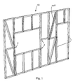
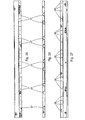
Fig. 1 is a perspective view of an assembled frame according to the invention; -
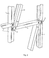
Fig. 2 is a perspective view of a joint detail of the frame; -
Fig. 3 is a perspective view of another joint detail of the frame; -
Fig. 4 is an exploded view of the joint detail ofFig. 3 ; -
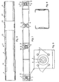
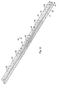
Fig. 5 is a perspective view of one frame element of the invention; -
Fig. 6 is a plan view of the frame element ofFig. 5 ; -
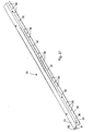
Fig. 7 is an elevational view of the frame element ofFig. 5 ; -
Fig. 8 is an end view of the frame element ofFig. 5 ; -
Fig. 9 is an enlarged view of detail A (seeFig. 7 ) of the frame element; -
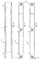
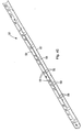
Fig. 10 is a plan view of an alternative frame element with a rail connector at one (left hand) end and a male end track connector at an opposite end; -
Figs. 11 and 12 are elevational views of the frame element ofFig. 10 with different arrangement of end chamfers; -
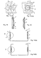
Figs. 13(a) and 13(b) are elevational views of end portions of another frame element of the invention; -
Figs. 14(a) and 14(b) are cross sectional views on the lines X-X and Y-Y inFig. 13(a) and 13(b) ; -
Fig. 15 is a cross sectional view of detail B inFig. 14(a) ; -
Fig. 16 is a cross sectional view of detail C inFig. 14(b) ; -
Fig. 17 is an elevational view of end portions of another frame element; -
Fig. 18 is a cross sectional view on the line II- II inFig. 20 ; -
Fig. 19 is a detailed view of the detail D ofFig. 18 ; -
Fig. 20 is a detailed view of an alternative locator of the invention; -
Fig. 21 is a cross sectional view of a joint interconnecting frame elements; -
Figs. 22 is a perspective view of one element of the joint ofFig. 21 ; -
Fig. 23 is a perspective view of another element of the joint ofFig. 21 ; -
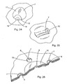
Figs. 24 and 25 are detailed perspective views from above and below the element; -
Fig. 26 is a partially cut away perspective view of the joint ofFig. 21 ; -
Figs. 27 and 28 are perspective views of a frame of the invention mounted to form a partition wall; -
Figs. 29 and 30 are perspective and cross-sectional views respectively of the detail L ofFig. 28 ; -
Figs. 31 and32 are perspective views of a base support element of the invention; -
Figs. 33 and34 are perspective views of an alternative base support element of the invention; -
Figs. 35, 36 and 37 are plan views from above the front and below the base support element ofFigs. 33 and34 ; -
Fig. 38 is a cross sectional view of detail M ofFig. 28 ; -
Figs. 39 and40 are perspective views of the lower and upper components of the upper support element ofFig. 38 ; - Referring to the drawings there is illustrated a
framing system 10 comprising a number offrame elements 1 typically of metal, in this case steel sections, connected atjoints 2. - The
frame element 1 comprises an elongated generally c-shaped lipped channel having a web, and side flanges which extend continuously the length of the element. Eachelement 1 comprises at least one connector portion comprising amale connector 4 or afemale connector 3. Each joint 2 comprises the interconnection of amale connector 4 with afemale connector 3 of anadjacent element 1. Theelement 1 comprises alip 12 which extends inwardly at the top of the side flanges. - The
male connector 4 comprises oppositely arranged on each of the side flanges of theelement 1, a fixingregion 5 in this case comprising a fixing hole, a raisedguide 6 and at least two locators spaced apart around the fixing hole and guide. The raisedguide 6 is concentric with the fixinghole 5. The locators are equispaced around the fixing hole on radii extending from the fixing hole. The locators comprisemale protuberances 7 protruding inwardly on the counterform/inside of theelement 1. The raisedguide 6 also protrudes inwardly on the inside of theelement 1. Theprotuberances 7 comprise lockingmembers 15 for locking engagement with thefemale connector 3 of anadjacent element 1. - The
female connector 3 comprises oppositely arranged on each of the side flanges of theelement 1, a fixingregion 9 in this case comprising a fixing hole, a recessedguide 10 and at least two locators equispaced around the fixing hole and guide. The recessedguide 10 protrudes inwardly on the inside of theelement 1. The locators comprise female receivingholes 8 for receiving themale protuberances 7 in locking engagement. - There are at least two locators and in this case four
locators regions female connectors - The male and
female connectors female connector portion 3 is inserted inside amale connector portion 4 and the connectors are inter-engaged and fixed. - As shown in the drawings, in this case the
element 1 has a swaged form at thefemale connector portion 3 to enable it to be inserted inside anadjacent element 1 at amale connector portion 4. The frame element is swaged at more than 1 and no more than 4 times the thickness of the material of the element. The provision of the swage allows for tolerance between the elements. Thelip 12 is omitted at themale connector portion 4 to enable insertion of thefemale connector portion 3 into close abutting engagement with the male connector. - The
element 1 may comprise at themale connector portion 4 anopen base portion 13. This is to enable the adjacent element to be inserted through the first element for interconnection at particular orientation. This is suitable in applications where lateral restraint is required. - In the embodiment illustrated the
female connector 3 is located inside themale connector 4 to form a joint 2. Theguides regions guide 6 of the male connector is raised relative to the recessedguide 10 of the female connector. The raisedguide 6 is received in the recessedguide 10 as theconnectors - The complementary forms of the
guides connectors respective fixing holes adjacent frame elements 1 relative to each other to enable engagement of thelocators - As shown in the drawings
rail frame elements 100 may also be connected to the frame elements. Referring toFigs. 10 to 12 therail frame element 100 is shown in further detail. Theelements 100 comprise chamfered ends 14. Therail frame elements 100 are used in applications where a non-perpendicular connection is required. - Preferred forms of the locators and connectors of the
fame elements 1 are described with reference to the drawings and in particularFigs. 17 to 26 . - The locking
members 15 of themale protuberances 7 engage with thefemale receiver holes 8 to prevent rotation of the frame members relative to each other once the male and female locators are engaged. - The
protuberances 7 are formed by partially shearing through/ drawing through theelement 1. Theprotuberances 7 comprise anelongated ridge 17 having shear edges at both ends. The shear edges define the lockingmembers 15 for locking engagement with theinternal wall 19 of the female receiving holes 8. The shear edges 15 are arranged substantially at right angles to the frame element. - The
protuberances 7 may have a substantially V-shaped lateral cross-section or alternatively a substantially U-shaped lateral cross-section as shown inFigs. 19 and 20 (in the detailed drawings the form of the protuberances is exaggerated for clarity). - In the embodiments illustrated the height of the
protuberance 7 is equal to or less than the depth of the receiving hole so that the top of theprotuberance 7 does not protrude out through the receivinghole 8 on engagement. - The
male protuberances 7 have by virtue of the manner in which they are formed a thickness substantially the same as the thickness of the material of the frame element. Theinternal wall 19 has a generally cylindrical form and extends through the thickness of the frame element. Theinternal wall 19 extends substantially at right angles to the frame element. - The locking engagement of the male and female locators is thus particularly secure since it is provided by a positive engagement through substantially the full thickness of the elements.
- The shear edges 15 at both ends of the
ridge 17 are positively and securely engaged with the female receiving holes 8 and by their form are substantially prevented from rotating in thehole 8. As a result, the adjacent frame elements are securely locked and any rotational movement substantially prevented once themale protuberances 7 are engaged in thefemale receivers 8. - In one embodiment the elongated ridges extend radially relative to the fixing
hole 5, in this case all of the ridges of the locators are substantially in aligned in the same direction. Alternatively the ridges may be arranged so that all points on the ridges are of similar distance from the fixinghole 5, the ridges having an approximately circumferential orientation relative to the fixing hole. The ridges are not rounded in form to follow a circumferential line. In this case the ridges of the locators on opposite sides of the fixing hole run parallel to each other. The arrangement of the plural locators and receivers spaced apart around the fixing region provides for a highly secure connection of adjacent frame elements. - When the
connectors respective locators member 11 through the aligned fixingholes member 11 may be of the nut and bolt type illustrated. The fixingmember 11 is selected so that the head of the fixing is accommodated in theguide 6 on the outside of the element. When the fixing member is inserted and tightened theprotuberances 7 are clamped into theholes 8 ensuring a very secure connection between the frame elements. - As noted above the frame elements may comprise fixing
regions female fixing regions 5 and/or 9 may comprise a pilot hole in which case pop rivets used to connect the frame elements together. In a further arrangement the fixingregion 5 and/or 9 may comprising fixing holes sized for use with a staked fixing. In a still further arrangement either of the fixingregion 5 and/or 9 may comprise a clearance hole for use with a self tapping screw. Clearly any suitable combination of the above may be used. - The male and female connection3, 4 and
locators - The differing profiles of the male and female locators are particularly important in ensuring a good connection between the frame elements. The connection at the joint has the advantages of being particularly secure.
- It will be appreciated that the system may be used to join adjacent frame elements in any application such as a
wall type frame 10 as illustrated inFig. 1 to which cladding panels may be attached. Such a wall may be load bearing or non load bearing and may, for example, form part of a modular building unit. - Referring to
Figs. 27 and 28 , aframe 25 comprised ofinterconnected frame elements 1 is mounted between anupper support structure underlying support structure 28. Theframe 25 forms a partition wall which extends from thefloor 28 to theceiling 27. - The
frame 25 is mounted to theunderlying support structure 28 by means of abase support element 30 and to theupper support structure upper support element 50. - Referring to
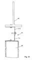
Figs. 29 to 37 , thebase support element 30 has an elongate form comprising front andback legs top support 33, and a protruding fixingmember 35. The protruding fixingmember 35 extends outwardly from the base of thefront leg 34. Thebase support element 30 may further comprise a stabilisingmember 31 extending inwardly from the base of theback leg 32. The stabilisingmember 31 serves to provide support and reinforcement for the base support element and theframe 25. The fixingmember 35 and stabilisingmember 31 are continuous and integrally formed with the support element. The fixing and stabilising members extend substantially at right angles to the front and back legs respectively. - The fixing
member 35 includes a plurality of fixing holes 36. The base support element is anchored securely to the underlying supportingstructure 28 by means of inserting fixing means through the fixing holes 36. - Referring to
Fig. 37 abase support element 40 is described. Thebase support element 40 is similar to theelement 30 and like features have been identified by similar reference numerals. Thefront leg 34 further comprises a plurality ofholes 37. Theholes 37 are sheared through or punched through holes provided in the facingwall 34 adjacent to the fixingmember 35. Theholes 37 have a generally semicircular form. These are to allow the screed to enter thebase support element 40. This provides for an improved seal between the base support element and the supporting structure and is particularly important in applications where acoustic performance is of importance. - In use the
back leg 32 of the support element is positioned near to the outer edge of thesupport structure 28 for example a floor slab. The stabilisingmember 31 which extends inwardly from theback leg 32 provides support and reinforcement for thebase support element base support element structure 28. - When the
base support element frame 25 is then mounted to it by inserting plurality of self-tapping or self-drilling screws through theframe member 25 into the top support 22 thereof. - While in the embodiments described the fixing and stabilising members are continuous it will be appreciated that they may comprise a suitable alternative form. Also while in the embodiments described the fixing member and inner support are integrally formed with the support element is will be appreciated that either may be formed separately for connection thereto.
- The invention also provides an
upper support element 50 for connecting the top of theframe 25 to anupper support structure upper support element 50 comprises two connectors namely a firstupper connector 55 and a secondlower connector 51. - In the embodiment illustrated the upper and
lower connectors - The
upper connector 55 comprises aweb 7 and aflange 6. Theweb 7 is configured for connection to the supportingstructure flange 6 depends from theweb 7 and is configured for connection to thelower connector 51. Theflange 6 comprises a plurality ofslots 59. Theslots 59 have an elongate form and are vertically oriented. Theweb 7 comprises a plurality of fixingholes 58 for fixing to thesupport structure 26 which may be of metal. - The
slots 59 are configured to allow for downward deflection of thesupport structure - The
lower connector 51 similarly comprises aweb 3 and anupstanding flange 2. The web and flange are substantially flat and planar. Theflange 2 is configured for connection to theflange 6 of the upper connector. Theweb 3 is configured for connection to the top of the frame to be mounted. - The upper and
lower components respective flanges slots 59 in theupper component 55 allow for some movement on assembly and some repositioning of thecomponents - In use the
lower component 1 is connected to the top of the frame prior to connection of theupper component 55 and prior to mounting the frame. Thelower component 51 is connected to the frame by inserting a self drilling or self-tapping screw through theweb 3. - The frame system of the invention has advantages as follows:
- The framing system and frame elements of the invention provide an improved means for connecting frame elements. The connectors comprise male and female connectors having respective locking members configured for positive locking engagement. The locking members are configured so that on engagement the frame elements are held securely at the required orientation relative to each other. Furthermore by virtue of their arrangement the locking members substantially prevent any rotation of the elements relative to each other once the respective locking members are engaged. The arrangement is also very strong since the corresponding locking members are configured to engage each other through the thickness of the material of the frame elements. The locking members comprise male locking members and female lock receivers which have different profiles each being configured for a strong positive engagement with the corresponding member.
- The frame elements of the invention further have the advantage that they are easy to assemble. In addition the locators are integral with the elements eliminating the need for separate components.
- The base support element of the invention has further advantages as follows:
- by virtue of its structure the base support element serves to raise the top support above the screed depth and is available in different sizes for use with different screed thickness
- allows the time consuming steps of setting out and packing to level and anchoring of wall to take place before costly cranes are on site
- displaces the anchor fastening away from the edge of the slab giving a more secure and higher capacity connection - fewer anchors are needed
- connection of frame to in-situ base support element is via self drilling self tapping screws allowing rapid assembly of frames into position and maximising crane utilisation
- shape allows vertical deflection of floors to take place under live loading without straining fasteners or the support element through excessive load transfer
- may potentially be used for the passage of services eg electrical data for plumbing
- by allowing the screed to enter the element an improved seal is achieved between the elements and support structure
- the base support element has advantages for applications where acoustic performance is of importance
- The upper support element has further advantages including the following:
- ease and flexibility of handling due to configuration comprising two separate components
- ease of use the components are configured for connection to the support in the order and manner required by the on-site circumstances
- setting out can be completed prior to arrival of cranes on site
- the upper support element allows for vertical connection of the components which provides for increased flexibility and ease of handling on site
- the provision of a two component upper support element in which the components are connected vertically allows for the upper component to be connected through to the lower component horizontally
- the form and manner of connection of the upper support element components allows for downward deflection of the floor without placing a structural load on the frame
Claims (51)
- A framing system (10) comprising a number of frame elements (1), at least some of the frame elements (1) being configured for interconnection with adjacent frame elements (1) on assembly, a frame element (1) comprising at least one connector (3, 4) comprising a male connector (4) or a female connector (3) for interconnection with a respective female or male connector (3,4) of an adjacent like frame element (1),
the male connector (4) comprising a fixing region and a male locator, the fixing region having a hole (5) and a raised guide (6) surrounding the hole (5),
the female connector (3) comprising a fixing region and a female locator, the fixing region having a hole (9) and a recessed guide (10) surrounding the hole (9), the guide (6) of the male connector (4) of one frame element (1) being engagable with the guide (10) of the female connector (3) of another frame element (1);
whereby the male locator comprises a protuberance (7) extending from the male connector, the male connector having at least two protuberances (7);
characterised in that the female locators comprises a through hole (8), the female connector having at least two through holes (8); and in that
the male protuberances (7) define locking members and the through holes (8) define lock receivers, the protuberances (7) being configured to lock adjacent frame elements at a particular orientation relative to each other when the protuberances (7) of one frame element are engaged and locked in the corresponding through holes (8) of another frame element to substantially prevent rotation of the adjacent frame elements (1) when engaged. - A system as claimed in claim 1, wherein the locators (7, 8) are equispaced from the associated fixing region.
- A system as claimed in any preceding claim wherein the male and female connectors (3, 4) each comprise four locators (7, 8) which are equispaced around the fixing region on radii extending from the fixing region (5, 9).
- A system as claimed in any preceding claims wherein the locators (7) of the male connector (4) are formed in the frame elements by shearing or drawing through.
- A system as claimed in any of claim 1 to 4 wherein the protuberance (7) comprises an elongate form.
- A system as claimed in any of claims 1 to 5 wherein the protuberance (7) comprises a ridge form.
- A system as claimed in any of claims 1 to 6 wherein the protuberance (7) comprises a substantially u-shaped cross section.
- A system as claimed in any of claims 1 to 6 wherein the protuberance (7) comprises a substantially v-shaped cross section.
- A system as claimed in claims 1 to 8 wherein the protuberance (7) comprises front and back lateral faces (15) defining the locking members.
- A system as claimed in claim 9 wherein the front and back lateral faces comprise a shear edge (15).
- A system as claimed in claims 9 to 10 wherein the lateral faces (15) protrude substantially at right angles to the frame element.
- A system as claimed in claims 6 to 11 wherein the ridge extends in a substantially radial direction relative to the fixing region.
- A system as claimed in claims 6 to 11 wherein the ridge extends in a generally circumferential direction relative to the fixing region.
- A system as claimed in any of claims 1 to 13 wherein each through hole (8) comprise a generally cylindrical internal wall extending through the frame element substantially at right angles for receiving the protuberance (7).
- A system as claimed in any preceding claim wherein the frame element (1) comprises a generally channel form comprising a base web and first and second side flanges.
- A system as claimed in claim 15 wherein the side flanges comprise an inturned lip at the upper edge thereof to define a generally c-shaped form.
- A system as claimed in claim 16 wherein a portion of the inturned lip is removed to define a slot for receiving a portion of an adjacent frame element.
- A system as claimed in claim 17 wherein the frame element (1) comprises an inturned lip except at the male connector portion thereof.
- A system as claimed in any preceding claim wherein the frame element (1) comprises a swage at a portion thereof.
- A system as claimed in claim 19 wherein the frame element (1) comprises a swage at the female connector portion thereof.
- A system as claimed in any preceding claim wherein the guide (6) of the male connector (4) comprises a raised guide concentric with the hole (5) in the fixing region.
- A system as claimed in any preceding claim wherein the guide (10) of the female connector comprises a recessed guide concentric with the hole (9) in the fixing region.
- A system as claimed in any preceding claim wherein the hole (5,9) of the fixing region comprising a fixing hole.
- A system as claimed in any of claims 1 to 22 wherein the hole of the fixing region comprising a pilot hole for a fixing member.
- A system as claimed in any of claims 1 to 22 wherein the hole of the fixing region comprises a clearance hole for a fixing member.
- A frame element for a framing system as claimed in any of claims 1 to 25, the frame element having at least one connector (3, 4) comprising a male connector (4) or a female connector (3) for interconnection with a respective female or male connector (3, 4) of an adjacent like frame element, wherein
the male connector (4) comprises a fixing region and a male locator, the fixing region having a hole (5) and a raised guide (6) surrounding the hole (5);
the female connector (3) comprises a fixing region and a female locator, the fixing region having a hole (9) and a recessed guide (10) surrounding the hole (9), the guide (6) of the male connector (4) of one frame element being engagable with the guide (10) of the female connector (3) of another frame element;
characterised in that the male locator comprises a protuberance (7) extending from the male connector, the male connector having at least two protuberances (7);
the female locator comprising a through hole (8), the female connector having at least two through holes (8); and in that
the male protuberances (7) define locking members and the through holes (8) define lock receivers, the protuberances (7) being configured to lock adjacent fame elements at a particular orientation relative to each other when the protuberances (7) of one frame element are engaged and locked in the corresponding through holes (8) of another frame element to substantially prevent rotation of the adjacent frame elements when engaged. - A frame element as claimed in claim 26 comprising one or more male connectors (4).
- A frame element as claimed in claim 26 comprising one or more female connectors (3).
- A frame element as claimed in claim 26 comprising at least one male (4) and at least one female connector (3).
- A building system comprising a framing system as claimed in any of claims 1 to 24 and a base support element (30, 40) for mounting a frame (25) to an underlying support structure, the base support element (30, 40) comprising an upper support (33), and legs (32, 34) depending from the support (33), characterised in that the base support element (30, 40) comprises an integral fixing member (35) extending outwardly from one of the legs (34) for fixing the support element (30, 40) to a support structure, and an integral stabilising member (31) extending inwardly from one of the legs (32).
- A building system as claimed in claim 30 wherein the fixing member (35) is configured to enable the insertion of fixing pins therethrough to anchor the element (30.40) to the support structure.
- A building system as claimed in claim 31 wherein the fixing member (35) comprises a plurality of preformed fixing holes (36) to receive fixing pins.
- A building system as claimed in claims 30 to 32 wherein the fixing member (35) is continuous.
- A building system as claimed in any of claims 30 to 33 wherein the fixing member (35) is arranged substantially at right angles to the leg (34).
- A building system as claimed in claims 30 to 34 wherein the support (30, 40) defines a receiver configured to receive and support a structural member.
- A building system as claimed in claims 30 to 34 wherein the legs (32, 34) are configured to space the support apart from the support structure.
- A building system as claimed in claims 30 to 36 wherein one of the legs (34) comprises a plurality of spaced-apart screed entry holes (37).
- A building system as claimed in claim 37 wherein the screed entry holes (37) comprise through holes.
- A building system as claimed in claims 37 or 38 wherein the screed entry holes (37) comprise a semicircular form.
- A building system as claimed in any of claims 30 to 39 wherein the stabilising member (31) is arranged substantially at right angles to the leg (32).
- A building system as claimed in any of claims 30 to 40 wherein the stabilising member (31) extends between the two legs (32, 34).
- A building system as claimed in any of claims 30 to 41 wherein the stabilising member (31) is configured to stabilise the support element.
- A building system as claimed in any of claims 30 to 42 wherein the stabilising member (31) is continuous.
- A building system comprising a framing system as claimed in any of claims 1 to 25 and a support assembly (50) for connecting a frame (25) to an upper support structure (26), the support assembly comprising an upper connector (55) and a lower connector (51).
the upper and lower connectors having a substantially L-shaped form and comprising a web (53, 57) and a flange (52, 56),
the web (57) of the upper connector (55) being configured for connection to a support structure,
the web (53) of the lower connector (51) being configured for connection to a structural member, and
the flanges (56, 52) of the upper and lower connectors (51, 55) being configured for connection to each other, characterised in that the flange (56) of the upper connector (55) comprises a plurality of spaced-apart slots (59) which are vertically oriented. - A building system as claimed in claim 44 wherein the web (57) of the upper connector (55) comprises a plurality of fixing holes (58) spaced apart to enable connection to a support structure.
- A building system as claimed in claim 44 or 45 wherein the slots (59) are configured to enable deflection of a support structure without placing a load on a structural member.
- A building system as claimed in any of claims 44 to 46 wherein the webs of the upper and lower connectors are continuous.
- A building system as claimed in any of claims 44 to 47 wherein the flanges of the upper and lower connectors are continuous.
- A modular building system comprising a framing system as claimed in any of claims 1 to 25.
- A modular building system comprising a building system as claimed in any of claims 30 to 48.
- A modular building system as claimed in claim 49 or 50 comprising mounting means for mounting the framing system to form a partition wall and wherein the mounting means comprises a support element as defined in any of claims 30 to 36 for mounting to an underlying support structure and a support element as defined in any of claims 44 to 48 for mounting to an upper support structure.
Applications Claiming Priority (3)
| Application Number | Priority Date | Filing Date | Title |
|---|---|---|---|
| IE20040299 | 2004-04-29 | ||
| IE20040473 | 2004-07-14 | ||
| PCT/IE2005/000050 WO2005106146A1 (en) | 2004-04-29 | 2005-04-29 | A wall framing system |
Publications (2)
| Publication Number | Publication Date |
|---|---|
| EP1747328A1 EP1747328A1 (en) | 2007-01-31 |
| EP1747328B1 true EP1747328B1 (en) | 2011-06-15 |
Family
ID=34680477
Family Applications (1)
| Application Number | Title | Priority Date | Filing Date |
|---|---|---|---|
| EP05734920A Expired - Lifetime EP1747328B1 (en) | 2004-04-29 | 2005-04-29 | A wall framing system |
Country Status (4)
| Country | Link |
|---|---|
| EP (1) | EP1747328B1 (en) |
| AT (1) | ATE513091T1 (en) |
| GB (1) | GB2413834B (en) |
| WO (1) | WO2005106146A1 (en) |
Cited By (2)
| Publication number | Priority date | Publication date | Assignee | Title |
|---|---|---|---|---|
| WO2021029474A1 (en) * | 2019-08-14 | 2021-02-18 | 엘지전자 주식회사 | Smart wall |
| US20230175254A1 (en) * | 2021-12-06 | 2023-06-08 | Telling Industries, LLC | Blocking component for construction framing assembly and construction framing assembly comprising blocking component |
Families Citing this family (7)
| Publication number | Priority date | Publication date | Assignee | Title |
|---|---|---|---|---|
| US20100083606A1 (en) * | 2007-02-16 | 2010-04-08 | Jeff Paul Davis | Framing system of studs and rails connected together by adapter members |
| WO2010089424A1 (en) * | 2009-02-09 | 2010-08-12 | Uralita Iberia S.L. | Construction system for dry partitioning with a ceramic coating |
| DE102015224549A1 (en) * | 2015-12-08 | 2017-06-08 | Thyssenkrupp Ag | Escalator or moving walkway support construction and method of manufacturing at least one subsegment of an escalator or moving walkway support structure |
| WO2020033771A1 (en) * | 2018-08-08 | 2020-02-13 | Hyperframe Inc. | Framing assembly with modular connectors |
| GB2583362B (en) * | 2019-04-25 | 2021-12-08 | Quicktrak Ltd | Partition support structure mounting track |
| US11499314B1 (en) | 2021-07-13 | 2022-11-15 | Alexander Kushner | Modular building system, apparatus and method |
| GB2612060A (en) * | 2021-10-20 | 2023-04-26 | Ash & Lacy Holdings Ltd | Frame construction |
Family Cites Families (10)
| Publication number | Priority date | Publication date | Assignee | Title |
|---|---|---|---|---|
| US1988388A (en) * | 1933-01-06 | 1935-01-15 | Mioton Sidney Fitzhugh | Structural building frame |
| US2307126A (en) * | 1940-12-31 | 1943-01-05 | Robert W Green | Steel house construction |
| US3680271A (en) * | 1970-03-11 | 1972-08-01 | Guest Keen & Nettlefolds Ltd | Wall frame structures |
| CH610069A5 (en) * | 1976-04-21 | 1979-03-30 | Rb Corp | |
| CH618758A5 (en) * | 1977-04-04 | 1980-08-15 | Baumann Walter | Releaseable connection of profile pieces |
| GB2144822A (en) * | 1983-07-18 | 1985-03-13 | Mecol Limited | Elongate construction elements |
| GB2205624A (en) * | 1987-06-04 | 1988-12-14 | Cheng Huey Der | Structural frame components |
| GB2240375A (en) * | 1990-01-24 | 1991-07-31 | Martin Gauci | Metal corner bracket |
| DE9211636U1 (en) * | 1992-08-29 | 1992-11-12 | Loos, Hermann, Dipl.-Ing., 6380 Bad Homburg | Fastening device for a facade cladding |
| US6094872A (en) * | 1999-10-08 | 2000-08-01 | Steelcase Development Inc. | Partition and floor channel construction |
-
2005
- 2005-04-29 GB GB0508800A patent/GB2413834B/en not_active Expired - Lifetime
- 2005-04-29 EP EP05734920A patent/EP1747328B1/en not_active Expired - Lifetime
- 2005-04-29 WO PCT/IE2005/000050 patent/WO2005106146A1/en not_active Ceased
- 2005-04-29 AT AT05734920T patent/ATE513091T1/en not_active IP Right Cessation
Cited By (4)
| Publication number | Priority date | Publication date | Assignee | Title |
|---|---|---|---|---|
| WO2021029474A1 (en) * | 2019-08-14 | 2021-02-18 | 엘지전자 주식회사 | Smart wall |
| EP4015726A4 (en) * | 2019-08-14 | 2023-08-30 | LG Electronics Inc. | Smart wall |
| US12044005B2 (en) | 2019-08-14 | 2024-07-23 | Lg Electronics Inc. | Smart wall |
| US20230175254A1 (en) * | 2021-12-06 | 2023-06-08 | Telling Industries, LLC | Blocking component for construction framing assembly and construction framing assembly comprising blocking component |
Also Published As
| Publication number | Publication date |
|---|---|
| ATE513091T1 (en) | 2011-07-15 |
| EP1747328A1 (en) | 2007-01-31 |
| GB2413834B (en) | 2007-12-05 |
| WO2005106146A1 (en) | 2005-11-10 |
| GB2413834A (en) | 2005-11-09 |
| GB0508800D0 (en) | 2005-06-08 |
Similar Documents
| Publication | Publication Date | Title |
|---|---|---|
| US8074416B2 (en) | Structural members with gripping features and joining arrangements therefor | |
| US7223043B1 (en) | Structural members and joining arrangements therefor | |
| US7127862B2 (en) | Connectors, tracks and system for smooth-faced metal framing | |
| US5943838A (en) | Metal stud with bendable tab channel support | |
| US9181716B1 (en) | System for mounting elongated panels to a substructure | |
| WO2018045334A1 (en) | Building structural connection comprising an angular bracket | |
| EP3135834A1 (en) | Moment resisting kneewall connector | |
| EP2126236B1 (en) | A framing system of studs and rails connected together by adapter members | |
| MXPA00007243A (en) | Floor joist and support system therefor. | |
| US20090139176A1 (en) | Slotted Tabbed Rim Track and Building Method | |
| EP1747328A1 (en) | A wall framing system | |
| GB2436747A (en) | Framing system | |
| US20020020140A1 (en) | Interconnectable studs and tracks for a building system | |
| GB2436748A (en) | Framing System | |
| IE20070906A1 (en) | A framing system | |
| IE20050267A1 (en) | A framing system | |
| IE20070907A1 (en) | A framing system | |
| IE84895B1 (en) | A framing system | |
| IE84896B1 (en) | A framing system | |
| IE84874B1 (en) | A framing system | |
| US20070119843A1 (en) | Wall framing system | |
| US12338622B2 (en) | Adjustable metal framing system and connecton | |
| AU2016219648B2 (en) | Moment resisting kneewall connector | |
| JPS6037931Y2 (en) | panel mount | |
| AU8952098A (en) | Fastening system for structural framing elements |
Legal Events
| Date | Code | Title | Description |
|---|---|---|---|
| PUAI | Public reference made under article 153(3) epc to a published international application that has entered the european phase |
Free format text: ORIGINAL CODE: 0009012 |
|
| 17P | Request for examination filed |
Effective date: 20061110 |
|
| AK | Designated contracting states |
Kind code of ref document: A1 Designated state(s): AT BE BG CH CY CZ DE DK EE ES FI FR GB GR HU IE IS IT LI LT LU MC NL PL PT RO SE SI SK TR |
|
| AX | Request for extension of the european patent |
Extension state: AL BA HR LV MK YU |
|
| 17Q | First examination report despatched |
Effective date: 20070214 |
|
| GRAP | Despatch of communication of intention to grant a patent |
Free format text: ORIGINAL CODE: EPIDOSNIGR1 |
|
| GRAJ | Information related to disapproval of communication of intention to grant by the applicant or resumption of examination proceedings by the epo deleted |
Free format text: ORIGINAL CODE: EPIDOSDIGR1 |
|
| GRAP | Despatch of communication of intention to grant a patent |
Free format text: ORIGINAL CODE: EPIDOSNIGR1 |
|
| RBV | Designated contracting states (corrected) |
Designated state(s): AT BE BG CH CY CZ DE DK EE ES FI FR GR HU IS IT LI LT LU MC NL PL PT RO SE SI SK TR |
|
| GRAS | Grant fee paid |
Free format text: ORIGINAL CODE: EPIDOSNIGR3 |
|
| GRAA | (expected) grant |
Free format text: ORIGINAL CODE: 0009210 |
|
| AK | Designated contracting states |
Kind code of ref document: B1 Designated state(s): AT BE BG CH CY CZ DE DK EE ES FI FR GR HU IS IT LI LT LU MC NL PL PT RO SE SI SK TR |
|
| AX | Request for extension of the european patent |
Extension state: AL BA HR LV MK YU |
|
| REG | Reference to a national code |
Ref country code: CH Ref legal event code: EP |
|
| REG | Reference to a national code |
Ref country code: DE Ref legal event code: R096 Ref document number: 602005028543 Country of ref document: DE Effective date: 20110728 |
|
| REG | Reference to a national code |
Ref country code: NL Ref legal event code: VDEP Effective date: 20110615 |
|
| PG25 | Lapsed in a contracting state [announced via postgrant information from national office to epo] |
Ref country code: LT Free format text: LAPSE BECAUSE OF FAILURE TO SUBMIT A TRANSLATION OF THE DESCRIPTION OR TO PAY THE FEE WITHIN THE PRESCRIBED TIME-LIMIT Effective date: 20110615 Ref country code: SE Free format text: LAPSE BECAUSE OF FAILURE TO SUBMIT A TRANSLATION OF THE DESCRIPTION OR TO PAY THE FEE WITHIN THE PRESCRIBED TIME-LIMIT Effective date: 20110615 |
|
| PG25 | Lapsed in a contracting state [announced via postgrant information from national office to epo] |
Ref country code: AT Free format text: LAPSE BECAUSE OF FAILURE TO SUBMIT A TRANSLATION OF THE DESCRIPTION OR TO PAY THE FEE WITHIN THE PRESCRIBED TIME-LIMIT Effective date: 20110615 Ref country code: GR Free format text: LAPSE BECAUSE OF FAILURE TO SUBMIT A TRANSLATION OF THE DESCRIPTION OR TO PAY THE FEE WITHIN THE PRESCRIBED TIME-LIMIT Effective date: 20110916 Ref country code: FI Free format text: LAPSE BECAUSE OF FAILURE TO SUBMIT A TRANSLATION OF THE DESCRIPTION OR TO PAY THE FEE WITHIN THE PRESCRIBED TIME-LIMIT Effective date: 20110615 Ref country code: SI Free format text: LAPSE BECAUSE OF FAILURE TO SUBMIT A TRANSLATION OF THE DESCRIPTION OR TO PAY THE FEE WITHIN THE PRESCRIBED TIME-LIMIT Effective date: 20110615 Ref country code: CY Free format text: LAPSE BECAUSE OF FAILURE TO SUBMIT A TRANSLATION OF THE DESCRIPTION OR TO PAY THE FEE WITHIN THE PRESCRIBED TIME-LIMIT Effective date: 20110615 |
|
| PG25 | Lapsed in a contracting state [announced via postgrant information from national office to epo] |
Ref country code: NL Free format text: LAPSE BECAUSE OF FAILURE TO SUBMIT A TRANSLATION OF THE DESCRIPTION OR TO PAY THE FEE WITHIN THE PRESCRIBED TIME-LIMIT Effective date: 20110615 Ref country code: BE Free format text: LAPSE BECAUSE OF FAILURE TO SUBMIT A TRANSLATION OF THE DESCRIPTION OR TO PAY THE FEE WITHIN THE PRESCRIBED TIME-LIMIT Effective date: 20110615 |
|
| PG25 | Lapsed in a contracting state [announced via postgrant information from national office to epo] |
Ref country code: IS Free format text: LAPSE BECAUSE OF FAILURE TO SUBMIT A TRANSLATION OF THE DESCRIPTION OR TO PAY THE FEE WITHIN THE PRESCRIBED TIME-LIMIT Effective date: 20111015 Ref country code: EE Free format text: LAPSE BECAUSE OF FAILURE TO SUBMIT A TRANSLATION OF THE DESCRIPTION OR TO PAY THE FEE WITHIN THE PRESCRIBED TIME-LIMIT Effective date: 20110615 Ref country code: PT Free format text: LAPSE BECAUSE OF FAILURE TO SUBMIT A TRANSLATION OF THE DESCRIPTION OR TO PAY THE FEE WITHIN THE PRESCRIBED TIME-LIMIT Effective date: 20111017 Ref country code: CZ Free format text: LAPSE BECAUSE OF FAILURE TO SUBMIT A TRANSLATION OF THE DESCRIPTION OR TO PAY THE FEE WITHIN THE PRESCRIBED TIME-LIMIT Effective date: 20110615 |
|
| PG25 | Lapsed in a contracting state [announced via postgrant information from national office to epo] |
Ref country code: RO Free format text: LAPSE BECAUSE OF FAILURE TO SUBMIT A TRANSLATION OF THE DESCRIPTION OR TO PAY THE FEE WITHIN THE PRESCRIBED TIME-LIMIT Effective date: 20110615 Ref country code: SK Free format text: LAPSE BECAUSE OF FAILURE TO SUBMIT A TRANSLATION OF THE DESCRIPTION OR TO PAY THE FEE WITHIN THE PRESCRIBED TIME-LIMIT Effective date: 20110615 Ref country code: PL Free format text: LAPSE BECAUSE OF FAILURE TO SUBMIT A TRANSLATION OF THE DESCRIPTION OR TO PAY THE FEE WITHIN THE PRESCRIBED TIME-LIMIT Effective date: 20110615 |
|
| PLBE | No opposition filed within time limit |
Free format text: ORIGINAL CODE: 0009261 |
|
| STAA | Information on the status of an ep patent application or granted ep patent |
Free format text: STATUS: NO OPPOSITION FILED WITHIN TIME LIMIT |
|
| 26N | No opposition filed |
Effective date: 20120316 |
|
| PG25 | Lapsed in a contracting state [announced via postgrant information from national office to epo] |
Ref country code: IT Free format text: LAPSE BECAUSE OF FAILURE TO SUBMIT A TRANSLATION OF THE DESCRIPTION OR TO PAY THE FEE WITHIN THE PRESCRIBED TIME-LIMIT Effective date: 20110615 |
|
| PG25 | Lapsed in a contracting state [announced via postgrant information from national office to epo] |
Ref country code: DK Free format text: LAPSE BECAUSE OF FAILURE TO SUBMIT A TRANSLATION OF THE DESCRIPTION OR TO PAY THE FEE WITHIN THE PRESCRIBED TIME-LIMIT Effective date: 20110615 |
|
| REG | Reference to a national code |
Ref country code: DE Ref legal event code: R097 Ref document number: 602005028543 Country of ref document: DE Effective date: 20120316 |
|
| PG25 | Lapsed in a contracting state [announced via postgrant information from national office to epo] |
Ref country code: MC Free format text: LAPSE BECAUSE OF NON-PAYMENT OF DUE FEES Effective date: 20120430 |
|
| REG | Reference to a national code |
Ref country code: CH Ref legal event code: PL |
|
| PG25 | Lapsed in a contracting state [announced via postgrant information from national office to epo] |
Ref country code: LI Free format text: LAPSE BECAUSE OF NON-PAYMENT OF DUE FEES Effective date: 20120430 Ref country code: CH Free format text: LAPSE BECAUSE OF NON-PAYMENT OF DUE FEES Effective date: 20120430 |
|
| PG25 | Lapsed in a contracting state [announced via postgrant information from national office to epo] |
Ref country code: ES Free format text: LAPSE BECAUSE OF FAILURE TO SUBMIT A TRANSLATION OF THE DESCRIPTION OR TO PAY THE FEE WITHIN THE PRESCRIBED TIME-LIMIT Effective date: 20110926 |
|
| PG25 | Lapsed in a contracting state [announced via postgrant information from national office to epo] |
Ref country code: BG Free format text: LAPSE BECAUSE OF FAILURE TO SUBMIT A TRANSLATION OF THE DESCRIPTION OR TO PAY THE FEE WITHIN THE PRESCRIBED TIME-LIMIT Effective date: 20110915 |
|
| PG25 | Lapsed in a contracting state [announced via postgrant information from national office to epo] |
Ref country code: TR Free format text: LAPSE BECAUSE OF FAILURE TO SUBMIT A TRANSLATION OF THE DESCRIPTION OR TO PAY THE FEE WITHIN THE PRESCRIBED TIME-LIMIT Effective date: 20110615 |
|
| PG25 | Lapsed in a contracting state [announced via postgrant information from national office to epo] |
Ref country code: LU Free format text: LAPSE BECAUSE OF NON-PAYMENT OF DUE FEES Effective date: 20120429 |
|
| PG25 | Lapsed in a contracting state [announced via postgrant information from national office to epo] |
Ref country code: HU Free format text: LAPSE BECAUSE OF FAILURE TO SUBMIT A TRANSLATION OF THE DESCRIPTION OR TO PAY THE FEE WITHIN THE PRESCRIBED TIME-LIMIT Effective date: 20050429 |
|
| REG | Reference to a national code |
Ref country code: FR Ref legal event code: PLFP Year of fee payment: 11 |
|
| PGFP | Annual fee paid to national office [announced via postgrant information from national office to epo] |
Ref country code: FR Payment date: 20150430 Year of fee payment: 11 |
|
| PGFP | Annual fee paid to national office [announced via postgrant information from national office to epo] |
Ref country code: DE Payment date: 20150630 Year of fee payment: 11 |
|
| REG | Reference to a national code |
Ref country code: DE Ref legal event code: R119 Ref document number: 602005028543 Country of ref document: DE |
|
| REG | Reference to a national code |
Ref country code: FR Ref legal event code: ST Effective date: 20161230 |
|
| PG25 | Lapsed in a contracting state [announced via postgrant information from national office to epo] |
Ref country code: FR Free format text: LAPSE BECAUSE OF NON-PAYMENT OF DUE FEES Effective date: 20160502 Ref country code: DE Free format text: LAPSE BECAUSE OF NON-PAYMENT OF DUE FEES Effective date: 20161101 |