EP1746612A1 - Electric double-layer capacitor and production method therefor - Google Patents
Electric double-layer capacitor and production method therefor Download PDFInfo
- Publication number
- EP1746612A1 EP1746612A1 EP05737327A EP05737327A EP1746612A1 EP 1746612 A1 EP1746612 A1 EP 1746612A1 EP 05737327 A EP05737327 A EP 05737327A EP 05737327 A EP05737327 A EP 05737327A EP 1746612 A1 EP1746612 A1 EP 1746612A1
- Authority
- EP
- European Patent Office
- Prior art keywords
- value
- anion
- cation
- layer capacitor
- double layer
- Prior art date
- Legal status (The legal status is an assumption and is not a legal conclusion. Google has not performed a legal analysis and makes no representation as to the accuracy of the status listed.)
- Granted
Links
Images




Classifications
-
- H—ELECTRICITY
- H01—ELECTRIC ELEMENTS
- H01G—CAPACITORS; CAPACITORS, RECTIFIERS, DETECTORS, SWITCHING DEVICES, LIGHT-SENSITIVE OR TEMPERATURE-SENSITIVE DEVICES OF THE ELECTROLYTIC TYPE
- H01G11/00—Hybrid capacitors, i.e. capacitors having different positive and negative electrodes; Electric double-layer [EDL] capacitors; Processes for the manufacture thereof or of parts thereof
- H01G11/22—Electrodes
- H01G11/30—Electrodes characterised by their material
- H01G11/32—Carbon-based
-
- H—ELECTRICITY
- H01—ELECTRIC ELEMENTS
- H01G—CAPACITORS; CAPACITORS, RECTIFIERS, DETECTORS, SWITCHING DEVICES, LIGHT-SENSITIVE OR TEMPERATURE-SENSITIVE DEVICES OF THE ELECTROLYTIC TYPE
- H01G11/00—Hybrid capacitors, i.e. capacitors having different positive and negative electrodes; Electric double-layer [EDL] capacitors; Processes for the manufacture thereof or of parts thereof
- H01G11/22—Electrodes
- H01G11/24—Electrodes characterised by structural features of the materials making up or comprised in the electrodes, e.g. form, surface area or porosity; characterised by the structural features of powders or particles used therefor
-
- H—ELECTRICITY
- H01—ELECTRIC ELEMENTS
- H01G—CAPACITORS; CAPACITORS, RECTIFIERS, DETECTORS, SWITCHING DEVICES, LIGHT-SENSITIVE OR TEMPERATURE-SENSITIVE DEVICES OF THE ELECTROLYTIC TYPE
- H01G11/00—Hybrid capacitors, i.e. capacitors having different positive and negative electrodes; Electric double-layer [EDL] capacitors; Processes for the manufacture thereof or of parts thereof
- H01G11/22—Electrodes
- H01G11/26—Electrodes characterised by their structure, e.g. multi-layered, porosity or surface features
-
- H—ELECTRICITY
- H01—ELECTRIC ELEMENTS
- H01G—CAPACITORS; CAPACITORS, RECTIFIERS, DETECTORS, SWITCHING DEVICES, LIGHT-SENSITIVE OR TEMPERATURE-SENSITIVE DEVICES OF THE ELECTROLYTIC TYPE
- H01G11/00—Hybrid capacitors, i.e. capacitors having different positive and negative electrodes; Electric double-layer [EDL] capacitors; Processes for the manufacture thereof or of parts thereof
- H01G11/84—Processes for the manufacture of hybrid or EDL capacitors, or components thereof
- H01G11/86—Processes for the manufacture of hybrid or EDL capacitors, or components thereof specially adapted for electrodes
-
- Y—GENERAL TAGGING OF NEW TECHNOLOGICAL DEVELOPMENTS; GENERAL TAGGING OF CROSS-SECTIONAL TECHNOLOGIES SPANNING OVER SEVERAL SECTIONS OF THE IPC; TECHNICAL SUBJECTS COVERED BY FORMER USPC CROSS-REFERENCE ART COLLECTIONS [XRACs] AND DIGESTS
- Y02—TECHNOLOGIES OR APPLICATIONS FOR MITIGATION OR ADAPTATION AGAINST CLIMATE CHANGE
- Y02E—REDUCTION OF GREENHOUSE GAS [GHG] EMISSIONS, RELATED TO ENERGY GENERATION, TRANSMISSION OR DISTRIBUTION
- Y02E60/00—Enabling technologies; Technologies with a potential or indirect contribution to GHG emissions mitigation
- Y02E60/13—Energy storage using capacitors
Definitions
- the present invention relates to an electrical double layer capacitor and its manufacturing method
- An electrical double layer capacitor is required to be high in withstand voltage.
- the withstand voltage of an electrical double layer capacitor depends upon electrolyte. Conventionally, in order to obtain higher withstand voltage, trials and errors have been repeated. For example, many supposed solutes and solvents are combined to synthesize electrolyte, and the withstand voltage of the synthesized electrolyte is measured. When the result of withstand voltage measurement satisfies the intended withstand voltage, it is used as electrolyte for electrical double layer capacitors. In this way, the withstand voltage of capacitors is improved.
- the capacitance is adjusted with respect to positive electrode and negative electrode to manufacture electrical double layer capacitors.
- Such a conventional electrical double layer capacitor is disclosed for example in Japanese Patent No. 3405040 and Japanese Unexamined Publication No. 2004-71814 .
- electrolyte has an inherent withstand voltage.
- an electrical double layer capacitor cannot be used with a voltage higher than the inherent withstand voltage of the electrolyte used for it. This is because the deterioration of electrical characteristics such as reduction of capacitance and increase of internal resistance are accelerated, and also, the case becomes easier to break down due to electrolyte reaction accompanied by increase in the amount of gas generated. Also, it is possible to make the most of inherent withstand voltage of the electrolyte by adjusting the electrode capacitance of positive electrode and negative electrode, but even in that case, the capacitor cannot be used with a voltage higher than the inherent voltage of the electrolyte.
- An electrical double layer capacitor of the present invention includes a case, an electrolyte stored in the case, a positive electrode, a negative electrode, and a molecular sieve, the electrolyte contains a cation and an anion, and the molecular sieve suppresses either one or both of adsorption of the cation onto a surface of the positive electrode and adsorption of the anion onto a surface of the negative electrode.
- the electrical double layer capacitor of the present invention includes a case, an electrolyte stored in the case, a positive electrode, a negative electrode, and a molecular sieve, the electrolyte contains a cation and an anion, and the molecular sieve suppresses either one or both of adsorption of the cation onto a surface of the positive electrode and adsorption of the anion onto a surface of the negative electrode.
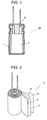
- Fig. 1 to Fig. 3 show an electrical double layer capacitor of the preferred embodiment.
- Electrical double layer capacitor 20 is configured in that element 2 is sealed in outer case 1 by sealing rubber 3.
- Element 2 is formed of strip-shaped separators 4 and strip-shaped collectors 5, 6.
- Collectors 5, 6 are spirally wound at surfaces and backs of separators 4.
- Active carbons 7A, 7B are respectively provided on surfaces of collectors 5, 6, the surfaces are facing to separator 4.
- Active carbon 7A is, as shown in Fig. 12 mentioned later, has active carbon pore 19A (hereinafter referred to as pore 19A) which acts as a second molecular sieve.
- Active carbon 7B is, as shown in Fig.
- pore 19B active carbon pore 19B which acts as a first molecular sieve.
- electrolyte 8 filled in outer case 1 exists between collector 5 and collector 6.
- Negative electrode 15 as a minus side electrode is formed by collector 5 and active carbon 7A.
- positive electrode 16 as a plus side electrode is formed by collector 6 and active carbon 7B.
- Aluminum is used for outer case 1 and collectors 5, 6 from the viewpoint of weight and conductivity. It is preferable to use materials such as stainless steel or nickel-plated iron for outer case 1 taking the strength into consideration. It is also preferable to use nickel or the like for collectors 5, 6.
- Sealing rubber 3 is made from a material not corroded by electrolyte such as ethylene-propylene rubber. Also, separator 4 is formed from non-woven fabric or porous film such as cellulose, polyethylene or polypropylene.
- Electrolyte 8 is formed of cation 9 and anion 10 as solute, solvent 12, and other additives (not shown). However, a solution not containing solvent 12 and the additives can be used for electrolyte 8. For example, an salt formed of 1-ethyl-3-methyl-imidazolium and tetrafluoroborate is dissolved salt liquefied at room temperature (25 degree), so solvent is not always needed.
- An inherent withstand voltage of electrolyte 8 can be defined as potential window from a current-voltage curve obtained by the electro-chemical measuring method or the like.
- the potential window is defined a size of voltage zone where the current is lower than a specific level on the current-voltage curve.
- the electro-chemical measuring method is, for example, cyclic voltammetry or linear sweep voltammetry using Pt electrode or glassy carbon electrode as working electrode.
- the withstand voltage of electrolyte 8 can be defined as the upper limit of voltage at which capacitance decreasing speed or internal resistance increasing speed with voltage applied is less than a specific value in a conventional electrical double layer capacitor having no molecular sieve.
- the potential window is the total value of oxidation potential and reduction potential, and in the voltage range inside the potential window, the oxidation-reduction reaction of electrolyte hardly takes place. Therefore, electrical double layer capacitor 20 using electrolyte 8 with greater potential window can be used with higher voltage, suppressing the capacitance decreasing speed or the internal resistance increasing speed.
- Electrolyte 8 used for measurement includes tetrafluoroborate (BF4 - ) as anion 10. Also, there are five kinds of electrolyte 8 including any one of tetra-ethyl-ammonium (TEA + ), 1-ethyl-3-methyl-imidazolium (EMI + ), 1,2,3-trimethyl-imidazolium (TMI + ), 5-aza-1-azonia-5-methyl-bicyclo[4,3,0]-nonane (AMN + ), 1,2,3,4-tetra-methyl-imidazolium (TMIL + ), as cation 9.
- TAA + tetra-ethyl-ammonium
- EMI + 1-ethyl-3-methyl-imidazolium
- TMI + 1,2,3-trimethyl-imidazolium
- AMN + 5-aza-1-azonia-5-methyl-bicyclo[4,3,0]-nonane
- TMIL + 1,2,3,4-tetra
- the current-voltage curve is obtained by cyclic voltammetry executing voltage scanning at 10 mV/sec. From the obtained current-voltage curve, reduction potential (Ered), oxidation potential (Eox) and potential window (Ew) are decided by the voltage value of which the current value is 1 mA/cm 2 .
- the reduction potential (Ered), the oxidation potential (Eox) and the potential window (Ew) are as shown in Table 1.
- the schematic diagram of the chemical structure of electrolyte 8 including cation 9 and anion 10 used in these measurements is shown in Fig. 7.
- Each electrolyte 8 includes tetrafluoroborate as anion 10, but it is clear that the obtained oxidation potential depends upon cation 9 combined with anion 10. This means that the oxidation potential of electrolyte 8 is not decided by anion 10 only, but it receives strong influences of interaction between cation 9 and anion 10 existing in the electrolyte.
- the reduction potential of electrolyte 8 is not decided by cation 9 only, but it receives strong influences of the interaction between cation 9 and anion 10 existing in the electrolyte 8.
- a molecular orbital calculation can be used for the simulation.
- a program code such as MOPAC93 (Fujitsu Co., Ltd.) or GAUSSIAN98 (Gaussian Inc.) can be used. The procedure will be described in the following by using the drawings.
- Fig. 4 is a model diagram of a portion of element 2 shown in Fig. 3. As shown in Fig. 4, electrolyte 8 exists in between collector 5 and collector 6. Also, in Fig. 4, since no voltage is applied between collector 5 and collector 6, cation 9 and anion 10 exist in electrolyte 8 in a state of being dispersed.
- Fig. 5 shows a state of power source 11 connected between collector 5 and collector 6.
- a minus electrode of power source 11 is connected to collector 5, and a plus electrode of power source 11 is connected to collector 6, respectively.
- cation 9 is attracted to a surface of active carbon 7A due to a negative charge of the surface of active carbon 7A.
- anion 10 is attracted to a surface of active carbon 7B due to the positive charge of the surface of active carbon 7B.
- energy is accumulated in electrical double layer capacitor 20.
- V R When a potential difference of more than a specific value V R is applied between cation 9 and the negative charge, electron moves from the surface of active carbon 7A to electrolyte 8. Also, when a potential difference of more than a specific value V 0 is applied between anion 10 and the positive charge, electron moves from electrolyte 8 to the surface of active carbon 7B.
- V R and V 0 are decided not only by just cation 9 and anion 10 but also receiving the influences of interaction between cation 9 and anion 10.
- the simulation based on the procedure shown in Fig. 6 the oxidation potential and reduction potential of electrolyte 8 are evaluated, and it is easily determined whether or not the oxidation potential and reduction potential can be increased. The determining procedure is explained in the following by using Fig. 6.
- electrolyte 8 is selected. Specifically, electrolyte 8 is supposedly formed of cation 9, anion 10, and solvent 12, as shown in Fig. 7. Also, Fig. 7 supposes that cation 9 is tetra-ethyl-ammonium, anion 10 is tetrafluoroborate, and solvent 12 is propylene carbonate. However, Fig. 7 is an example of electrolyte 8, and the configuration varies with electrolyte 8 selected.
- step S72A a model in which cation 9 and anion 10 are dissolved in solvent 12 is supposed.
- cation 9 and anion 10 form associated complex 14.
- associated complex 14 forms a dimer consisting of one cation 9 and one anion 10.
- a model in which the solute such as cation 9, anion 10, and associated complex 14 is dissolved in solvent 12 can be supposed by approximating solvent 12 as a polarizable continuum and storing the solute inside the continuum.
- the dissolution model of solute is not limited to this.
- step S73A energy of associated complex 14 is calculated by simulation when associated complex 14 formed by cation 9 and anion 10 is in a stable state.
- the calculated energy is called the first energy, and defined as the first value.
- the energy calculated here is the total energy of electron and atomic nucleus contained in the associated complex.
- the energies of electron and atomic nucleus include kinetic energy of electron, potential energy between electron and atomic nucleus, potential energy between atomic nucleus and atomic nucleus, and zero point vibrational energy of atomic nucleus. Further, thermal vibrational energy at limited temperature is sometimes added.
- step S74A energies when associated complex 14 in a state of step S73A is reduced or when associated complex 14 in a state of step S73A is oxidized is calculated by simulation.
- the calculated energies are called as the second energy and the third energy respectively, and defined as the second value and the third value.
- associated complex 14 when associated complex 14 is reduced, it means that electron has moved from active carbon 7A toward associated complex 14 existing near the surface of active carbon 7A. Also, when associated complex 14 is oxidized, it means that electron has moved from associated complex 14 existing near the surface of active carbon 7B toward active carbon 7B.
- step S75A the fourth value is obtained by subtracting the second value from the first value, and also, the fifth value is obtained by subtracting the first value from the third value.
- the fourth value means the gain of energy when associated complex 14 is reduced at the collector 5 side.
- the fifth value means the loss of energy when associated complex 14 is oxidized at the collector 6 side.
- the sixth value is obtained by subtracting the fourth value from the fifth value. It means that there is a possibility that the greater the sixth value, it means that there is a possibility that the potential window becomes greater.
- step S72B a model in which cation 9 or anion 10 is individually dissolved in solvent 12 is supposed.
- step S72B it is supposed that cation 9 or anion 10 does not form associated complex 14 but it exists individually.
- step S73B energy is calculated by simulation when cation 9 is individually in a stable state.
- the calculated energy is called the first C energy, and defined as the first C value.
- energy is calculated by simulation when anion 10 is individually in a stable state.
- the calculated energy is called the first A energy, and defined as the first A value.
- step S74B respective energies are calculated when cation 9 is reduced and when anion 10 is oxidized from the state of S73B.
- the calculated energies are respectively called the second C energy and the third A energy, and defined as the second C value and the third A value.
- cation 9 when cation 9 is reduced, it means that electron has moved from active carbon 7A toward cation 9 existing near the surface of active carbon 7A. Also, when anion 10 is oxidized, it means that electron has moved from anion 10 existing near the surface of active carbon 7B toward active carbon 7B.
- step S75B the fourth C value is obtained by subtracting the second C value from the first C value, and also, the fifth A value is obtained by subtracting the first A value from the third A value.
- the fourth C value means the gain of energy when cation 9 is reduced at the collector 5 side.
- the fifth A value means the loss of energy when anion 10 is oxidized at the collector 6 side.
- step S76 the fifth value is compared with the fifth A value.
- anion 10 does not form associated complex 14 in combination with cation 9, and it is determined that the oxidation potential becomes increased when the interaction between ions is lessened.
- a first molecular sieve is formed at the positive electrode 16 side.
- the fourth value is compared with the fourth C value.
- cation 9 does not form associated complex 14 in combination with anion 10, and it is determined that the reduction potential becomes increased when the interaction between ions is lessened.
- a second molecular sieve is formed at the negative electrode 15 side.
- HF/3-21+G Hardtree-Fock method, 3 - 21 + G basic function
- IPCM Isodensity Polarizable Continuum Model: J, B. Foresmanetal., Phys. Chem. 100, 16098 (1996 ).
- the sixth value is obtained by subtracting the obtained fourth value from the obtained fifth value.
- Fig. 9 shows the result of comparison with actual measured value Ew of potential window by cyclic voltammetry shown in Table 1.
- the fifth A value is larger than the fifth value except for electrolyte 8 including tetra-ethyl-ammonium (TEA + ) as cation 9. Therefore, anion 10 does not form associated complex 14 in combination with cation 9, and it can be determined that the oxidation potential becomes increased when the interaction between ions is lessened. In this case, there is a possibility that the oxidation potential is increased by about 2 V that is the difference between the fifth A value and the fifth value.
- TEA + tetra-ethyl-ammonium
- pore 19B of active carbon 7B serves as the first molecular sieve which prevents cation 9 from sticking to the surfaces of positive electrode 16, thereby displaying a molecular sieving function.
- the fourth value is compared with the fourth C value, and when the fourth value is larger, cation 9 does not form associated complex 14 in combination with anion 10, and it can be determined that the reduction potential becomes increased when the interaction between ions is lessened. In this case, there is a possibility that the reduction potential is increased for the potential difference between the fourth value and the fourth C value.
- negative electrode 15 of electrical double layer capacitor 20 is provided with a second molecular sieve having a molecular sieving function. As a result, only cation 9 is adsorbed onto the surface of negative electrode 15, and it is unable to adsorb anion 10. Consequently, cation 9 becomes unable to form associated complex 14 in combination with anion 10, thereby increasing the reduction potential.
- the extension of ions is defined by using equal electron density phase (0.001 a.u.) obtained by 3 - 21 + G basic function of Hartree-Fock method.
- the ion radius is defined by the radius of sphere having a volume equal to the ion volume obtained, and the result is shown in Table 3.
- Table 3 Chemical species Ion radius / angstrom BF 4 - 4.738 TEABF 4 8.221 EMIBF 4 6.173 TMIBF 4 6.085 AMNBF 4 5.910 TMILBF 4 5.721 (HF/3-31-G)
- the molecular sieve is preferable to be formed on coat 21 A or coat 21 B coating the surface of negative electrode 15 or positive electrode 16.
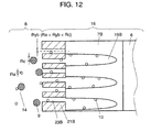
- Fig. 12 is a schematic diagram showing the first molecular sieve formed on coat 21 B coating the surface of positive electrode 16.
- Fig. 13 is a schematic diagram showing the second molecular sieve formed on coat 21 A coating the surface of negative electrode 15.
- pores 23B average pore radius of coat pores 23B (hereafter referred to as pores 23B) of coat 21 B is larger than the ion radius (Ra) of anion 10 and smaller than the ion radius (Rc) of cation 9 (Ra ⁇ Ryb ⁇ Rc). Then, only anion 10 can be adsorbed onto the surface of active carbon 7B that is positive electrode 16. That is, cation 9 is unable to pass through pores 23B, and is not adsorbed onto the porous surfaces of active carbon 7B. Pore 23B serves as the first molecular sieve which prevents cation 9 from sticking to the surfaces of positive electrode 16, thereby displaying a molecular sieving function.
- pores 23A the one whose average pore radius (Rya) of coat pores 23A (hereafter referred to as pores 23A) of coat 21 A is larger than the ion radius (Rc) of cation 9 and smaller than the ion radius (Ra) of anion 10 (Rc ⁇ Rya ⁇ Ra). Then, only anion 10 gets into pores 23A and is adsorbed onto the porous surfaces of active carbon 7A. Anion 10 is unable to pass through pores 23A, and is not adsorbed onto the porous surfaces of active carbon 7A. That is, pore 23A serves as the second molecular sieve which prevents anion 10 from sticking to the surfaces of negative electrode 15, thereby displaying a molecular sieving function.
- coat 21 A, 21 B for example, polymer and ceramics can be selected.
- the present invention is not limited to these.
- Coat 21A, 21 B are just required to satisfy such conditions that coat 21 A, 21 B do not dissolve or disappear in electrolyte 8 and that they do not cause the characteristics of negative electrode 15, positive electrode 16, or electrolyte 8 to be changed. That is, all kinds of materials can be used for coat 21 A, 21 B provided that they are capable of realizing a molecular sieving function without dissolving and changing the characteristics.
- the step of obtaining radius (Rc) of cation 9 and the radius (Ra) of anion 10 as the radius of sphere having same volume as the volume in the range of electron density being 0.001 a.u. or less it is preferable to combine the step before and after the procedure shown in Fig. 6.
- the average pore radius of pores 19A, 19B, 23A, 23B for realizing the first or the second molecular sieve can be easily defined.
- the step of forming active carbon 7A, 7B on negative electrode 15 or positive electrode 16 is combined with the procedure shown in Fig. 6, and thereby, electrical double layer capacitor 20 having a molecular sieve can be realized.
- the step of forming coat 21A, 21 B coating the surface of negative electrode 15 or positive electrode 16 is combined with the procedure shown in Fig. 6, and thereby, electrical double layer capacitor 20 having a molecular sieve can be realized.
- the average pore radius of the first molecular sieve is preferable to be 6 angstrom or less provided that cation 9 is 6 angstrom or over in ion radius. Accordingly, it becomes possible to make only tetrafluoroborate (BF4 - ) that is anion 10 selectively get absorbed onto the surface of positive electrode 16.
- the procedure shown in Fig. 6 supposes that the system for interaction of cation 9 and anion 10 is a dimer of cation 9 and anion 10 shown in Fig. 7.
- the associated complex is not limited to a dimer.
- dimer instead of dimer, it is preferable to suppose a trimer formed of one cation 9 and two anions 10, or a trimer formed of two cations 9 and one anion 10. Further, it is preferable to suppose all kinds of possible associated complex.
- the fourth value and the fifth value to the supposed associated complex are obtained, and the fifth A value to individual anion 10 and fourth C value to individual cation 9 are obtained.
- anion 10 does not form associated complex 14 in combination with cation 9.
- cation 9 does not form associated complex 14 in combination with anion 10.
- the interaction between ions is lessened to increase one or both of oxidation potential and reduction potential, thereby expanding the potential window. That is, the adsorption of cation 9 contained in electrolyte 8 onto the surface of positive electrode 16 of cation 9 is suppressed by the first molecular sieve. Also, the adsorption of anion 10 contained in electrolyte 8 onto the surface of negative electrode 15 of anion 10 is suppressed by the second molecular sieve.
- One or both of the molecular sieving function of the first and the second molecular sieve is provided to separate anion 10 from cation 9 in the vicinity of electrode surface. In this way, it is possible to provide electrical double layer capacitor 20 which may be provided high withstand voltage and long life.
- the electrical double layer capacitor and its manufacturing method of the present invention shortens the period required for the development of electrolyte and enables the manufacture of high-performance electrical double layer capacitors effectively using high withstand voltage characteristics.
Landscapes
- Engineering & Computer Science (AREA)
- Power Engineering (AREA)
- Microelectronics & Electronic Packaging (AREA)
- Chemical & Material Sciences (AREA)
- Materials Engineering (AREA)
- Manufacturing & Machinery (AREA)
- Electric Double-Layer Capacitors Or The Like (AREA)
Abstract
Description
- The present invention relates to an electrical double layer capacitor and its manufacturing method
- An electrical double layer capacitor is required to be high in withstand voltage. The withstand voltage of an electrical double layer capacitor depends upon electrolyte. Conventionally, in order to obtain higher withstand voltage, trials and errors have been repeated. For example, many supposed solutes and solvents are combined to synthesize electrolyte, and the withstand voltage of the synthesized electrolyte is measured. When the result of withstand voltage measurement satisfies the intended withstand voltage, it is used as electrolyte for electrical double layer capacitors. In this way, the withstand voltage of capacitors is improved.
- Also, for effectively utilizing such withstand voltage improvement of electrolyte, the capacitance is adjusted with respect to positive electrode and negative electrode to manufacture electrical double layer capacitors.
- Such a conventional electrical double layer capacitor is disclosed for example in
Japanese Patent No. 3405040 Japanese Unexamined Publication No. 2004-71814 - However, electrolyte has an inherent withstand voltage. And, an electrical double layer capacitor cannot be used with a voltage higher than the inherent withstand voltage of the electrolyte used for it. This is because the deterioration of electrical characteristics such as reduction of capacitance and increase of internal resistance are accelerated, and also, the case becomes easier to break down due to electrolyte reaction accompanied by increase in the amount of gas generated. Also, it is possible to make the most of inherent withstand voltage of the electrolyte by adjusting the electrode capacitance of positive electrode and negative electrode, but even in that case, the capacitor cannot be used with a voltage higher than the inherent voltage of the electrolyte.
- An electrical double layer capacitor of the present invention includes a case, an electrolyte stored in the case, a positive electrode, a negative electrode, and a molecular sieve, the electrolyte contains a cation and an anion, and the molecular sieve suppresses either one or both of adsorption of the cation onto a surface of the positive electrode and adsorption of the anion onto a surface of the negative electrode. In this configuration, it is possible to provide the electrical double layer capacitor having high withstand voltage and long life.
-
- Fig. 1 is a sectional view of an electrical double layer capacitor in the preferred embodiment of the present invention.
- Fig. 2 is a perspective view of an essential portion of an electrical double layer capacitor in the preferred embodiment of the present invention.
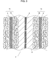
- Fig. 3 is an enlarged sectional view of an essential portion of an electrical double layer capacitor in the preferred embodiment of the present invention.
- Fig. 4 is a model diagram of an essential portion of an electrical double layer capacitor in the preferred embodiment of the present invention.
- Fig. 5 is a model diagram of an essential portion of an electrical double layer capacitor in the preferred embodiment of the present invention.
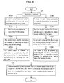
- Fig. 6 is a flow chart showing a manufacturing method for an electrical double layer capacitor in the preferred embodiment of the present invention.
- Fig. 7 is a schematic diagram of an electrolyte used for an electrical double layer capacitor in the preferred embodiment of the present invention.
- Fig. 8 is a chemical structure diagram of an electrolyte used for an electrical double layer capacitor in the preferred embodiment of the present invention.
- Fig. 9 is a characteristic diagram showing a value of potential window of an electrolyte used for an electrical double layer capacitor in the preferred embodiment of the present invention.
- Fig. 10 is a schematic diagram of an electrical double layer capacitor in the preferred embodiment of the present invention.
- Fig. 11 is a schematic diagram of an electrical double layer capacitor in the preferred embodiment of the present invention.
- Fig. 12 is a schematic diagram of an electrical double layer capacitor in the preferred embodiment of the present invention.
- Fig. 13 is a schematic diagram of an electrical double layer capacitor in the preferred embodiment of the present invention.
-
- 1
- Case
- 2
- Element
- 3
- Sealing rubber
- 4
- Separator
- 5, 6
- Collector
- 7A, 7B
- Active carbon
- 8
- Electrolyte
- 9
- Cation
- 10
- Anion
- 12
- Solvent
- 14
- Associated complex
- 15
- Negative electrode
- 16
- Positive electrode
- 19A, 19B
- Active carbon pore
- 21 A, 21 B
- Coat
- 23A, 23B
- Coat pore
- The preferred embodiment of the present invention will be described in the following with reference to the drawings.
- Fig. 1 to Fig. 3 show an electrical double layer capacitor of the preferred embodiment. Electrical
double layer capacitor 20 is configured in thatelement 2 is sealed inouter case 1 by sealingrubber 3.Element 2 is formed of strip-shapedseparators 4 and strip-shapedcollectors Collectors separators 4.Active carbons collectors separator 4.Active carbon 7A is, as shown in Fig. 12 mentioned later, hasactive carbon pore 19A (hereinafter referred to aspore 19A) which acts as a second molecular sieve.Active carbon 7B is, as shown in Fig. 11 mentioned later, hasactive carbon pore 19B (hereinafter referred to aspore 19B) which acts as a first molecular sieve. And,electrolyte 8 filled inouter case 1 exists betweencollector 5 andcollector 6.Negative electrode 15 as a minus side electrode is formed bycollector 5 andactive carbon 7A. Also,positive electrode 16 as a plus side electrode is formed bycollector 6 andactive carbon 7B. - Aluminum is used for
outer case 1 andcollectors outer case 1 taking the strength into consideration. It is also preferable to use nickel or the like forcollectors rubber 3 is made from a material not corroded by electrolyte such as ethylene-propylene rubber. Also,separator 4 is formed from non-woven fabric or porous film such as cellulose, polyethylene or polypropylene. -
Electrolyte 8 is formed ofcation 9 andanion 10 as solute, solvent 12, and other additives (not shown). However, a solution not containing solvent 12 and the additives can be used forelectrolyte 8. For example, an salt formed of 1-ethyl-3-methyl-imidazolium and tetrafluoroborate is dissolved salt liquefied at room temperature (25 degree), so solvent is not always needed. - An inherent withstand voltage of
electrolyte 8 can be defined as potential window from a current-voltage curve obtained by the electro-chemical measuring method or the like. The potential window is defined a size of voltage zone where the current is lower than a specific level on the current-voltage curve. Also, the electro-chemical measuring method is, for example, cyclic voltammetry or linear sweep voltammetry using Pt electrode or glassy carbon electrode as working electrode. Also, the withstand voltage ofelectrolyte 8 can be defined as the upper limit of voltage at which capacitance decreasing speed or internal resistance increasing speed with voltage applied is less than a specific value in a conventional electrical double layer capacitor having no molecular sieve. The potential window is the total value of oxidation potential and reduction potential, and in the voltage range inside the potential window, the oxidation-reduction reaction of electrolyte hardly takes place. Therefore, electricaldouble layer capacitor 20 usingelectrolyte 8 with greater potential window can be used with higher voltage, suppressing the capacitance decreasing speed or the internal resistance increasing speed. - For example, the withstand voltage of
electrolyte 8 is measured by the above method.Electrolyte 8 used for measurement includes tetrafluoroborate (BF4-) asanion 10. Also, there are five kinds ofelectrolyte 8 including any one of tetra-ethyl-ammonium (TEA+), 1-ethyl-3-methyl-imidazolium (EMI+), 1,2,3-trimethyl-imidazolium (TMI+), 5-aza-1-azonia-5-methyl-bicyclo[4,3,0]-nonane (AMN+), 1,2,3,4-tetra-methyl-imidazolium (TMIL+), ascation 9. Also, glassy carbon is used for working electrode, platinum for counter electrode, and Ag+/Ag for reference electrode. Further, the current-voltage curve is obtained by cyclic voltammetry executing voltage scanning at 10 mV/sec. From the obtained current-voltage curve, reduction potential (Ered), oxidation potential (Eox) and potential window (Ew) are decided by the voltage value of which the current value is 1 mA/cm2. The reduction potential (Ered), the oxidation potential (Eox) and the potential window (Ew) are as shown in Table 1. Also, the schematic diagram of the chemical structure ofelectrolyte 8 includingcation 9 andanion 10 used in these measurements is shown in Fig. 7.Table 1: Oxidation-reduction potentials measured by cyclic voltammetry (Solvent: propylene carbonate) Chemical species Reduction potential Ered Oxidation potential Eox Potential window Ew /Vvs. Ag+/Ag TEABF4 3.4 3.4 6.8 EMIBF4 2.6 2.2 4.8 TMIBF4 2.6 1.8 4.4 AMNBF4 2.5 1.7 4.2 TMILBF4 2.3 1.5 3.8 (GC, 1 mA/cm2, 10 mV/s) - Each
electrolyte 8 includes tetrafluoroborate asanion 10, but it is clear that the obtained oxidation potential depends uponcation 9 combined withanion 10. This means that the oxidation potential ofelectrolyte 8 is not decided byanion 10 only, but it receives strong influences of interaction betweencation 9 andanion 10 existing in the electrolyte. - Similarly, it can be considered that the reduction potential of
electrolyte 8 is not decided bycation 9 only, but it receives strong influences of the interaction betweencation 9 andanion 10 existing in theelectrolyte 8. - Accordingly, in a certain kind of
electrolyte 8, if the interaction betweencation 9 andanion 10 can be lessened, it is probably possible to increase either one or both of oxidation potential and reduction potential to expand the potential window. Also, whether or not aspecific electrolyte 8 has such an effect can be determined by means of simulation mentioned later. - A molecular orbital calculation can be used for the simulation. A program code such as MOPAC93 (Fujitsu Co., Ltd.) or GAUSSIAN98 (Gaussian Inc.) can be used. The procedure will be described in the following by using the drawings.
- Fig. 4 is a model diagram of a portion of
element 2 shown in Fig. 3. As shown in Fig. 4,electrolyte 8 exists in betweencollector 5 andcollector 6. Also, in Fig. 4, since no voltage is applied betweencollector 5 andcollector 6,cation 9 andanion 10 exist inelectrolyte 8 in a state of being dispersed. - Fig. 5 shows a state of
power source 11 connected betweencollector 5 andcollector 6. A minus electrode ofpower source 11 is connected tocollector 5, and a plus electrode ofpower source 11 is connected tocollector 6, respectively. Withpower source 11 connected,cation 9 is attracted to a surface ofactive carbon 7A due to a negative charge of the surface ofactive carbon 7A. Also, contrarily,anion 10 is attracted to a surface ofactive carbon 7B due to the positive charge of the surface ofactive carbon 7B. As a result, energy is accumulated in electricaldouble layer capacitor 20. - When a potential difference of more than a specific value VR is applied between
cation 9 and the negative charge, electron moves from the surface ofactive carbon 7A toelectrolyte 8. Also, when a potential difference of more than a specific value V0 is applied betweenanion 10 and the positive charge, electron moves fromelectrolyte 8 to the surface ofactive carbon 7B. The withstand voltage in electricaldouble layer capacitor 20 means VW (=VR + V0) where VR is added to V0, that is the size of potential window. - In the case of using the conventional electrode having no molecular sieve, not only one of
cation 9 andanion 10 but also both of them may approach the electrode surface. So, VR and V0 are decided not only by justcation 9 andanion 10 but also receiving the influences of interaction betweencation 9 andanion 10. And, by the simulation based on the procedure shown in Fig. 6, the oxidation potential and reduction potential ofelectrolyte 8 are evaluated, and it is easily determined whether or not the oxidation potential and reduction potential can be increased. The determining procedure is explained in the following by using Fig. 6. - First, in step S71,
electrolyte 8 is selected. Specifically,electrolyte 8 is supposedly formed ofcation 9,anion 10, and solvent 12, as shown in Fig. 7. Also, Fig. 7 supposes thatcation 9 is tetra-ethyl-ammonium,anion 10 is tetrafluoroborate, and solvent 12 is propylene carbonate. However, Fig. 7 is an example ofelectrolyte 8, and the configuration varies withelectrolyte 8 selected. - Next, in step S72A, a model in which
cation 9 andanion 10 are dissolved in solvent 12 is supposed. In step S72A, it is supposed thatcation 9 andanion 10 form associated complex 14. And, it is supposed that associated complex 14 forms a dimer consisting of onecation 9 and oneanion 10. A model in which the solute such ascation 9,anion 10, and associated complex 14 is dissolved in solvent 12 can be supposed by approximating solvent 12 as a polarizable continuum and storing the solute inside the continuum. However, the dissolution model of solute is not limited to this. - Next, in step S73A, energy of associated complex 14 is calculated by simulation when associated complex 14 formed by
cation 9 andanion 10 is in a stable state. The calculated energy is called the first energy, and defined as the first value. - The energy calculated here is the total energy of electron and atomic nucleus contained in the associated complex. The energies of electron and atomic nucleus include kinetic energy of electron, potential energy between electron and atomic nucleus, potential energy between atomic nucleus and atomic nucleus, and zero point vibrational energy of atomic nucleus. Further, thermal vibrational energy at limited temperature is sometimes added.
- Next, in step S74A, energies when associated complex 14 in a state of step S73A is reduced or when associated complex 14 in a state of step S73A is oxidized is calculated by simulation. The calculated energies are called as the second energy and the third energy respectively, and defined as the second value and the third value.
- Here, when associated complex 14 is reduced, it means that electron has moved from
active carbon 7A toward associated complex 14 existing near the surface ofactive carbon 7A. Also, when associated complex 14 is oxidized, it means that electron has moved from associated complex 14 existing near the surface ofactive carbon 7B towardactive carbon 7B. - That is, as associated complex 14 is reduced or oxidized, negative charge or positive charge stored in
negative electrode 15 orpositive electrode 16 moves intoelectrolyte 8. As a result, the energy stored in electricaldouble layer capacitor 20 is lost. Simultaneously,cation 9 andanion 10 forming associated complex 14 becomes nearly radical. And,cation 9 andanion 10 are liable to perform chemical reaction, andelectrolyte 8 becomes liable to break down. - Next, in step S75A, the fourth value is obtained by subtracting the second value from the first value, and also, the fifth value is obtained by subtracting the first value from the third value. Here, the fourth value means the gain of energy when associated complex 14 is reduced at the
collector 5 side. And, the fifth value means the loss of energy when associated complex 14 is oxidized at thecollector 6 side. - That is, it means that there is a possibility that the smaller the fourth value, the reduction potential becomes greater. And, it means that there is a possibility that the greater the fifth value, the oxidation potential becomes greater. Further, the sixth value is obtained by subtracting the fourth value from the fifth value. It means that there is a possibility that the greater the sixth value, it means that there is a possibility that the potential window becomes greater.
- On the other hand, in step S72B, a model in which
cation 9 oranion 10 is individually dissolved in solvent 12 is supposed. In step S72B, it is supposed thatcation 9 oranion 10 does not form associated complex 14 but it exists individually. - Next, in step S73B, energy is calculated by simulation when
cation 9 is individually in a stable state. The calculated energy is called the first C energy, and defined as the first C value. Similarly, energy is calculated by simulation whenanion 10 is individually in a stable state. The calculated energy is called the first A energy, and defined as the first A value. - Next, in step S74B, respective energies are calculated when
cation 9 is reduced and whenanion 10 is oxidized from the state of S73B. The calculated energies are respectively called the second C energy and the third A energy, and defined as the second C value and the third A value. - Here, when
cation 9 is reduced, it means that electron has moved fromactive carbon 7A towardcation 9 existing near the surface ofactive carbon 7A. Also, whenanion 10 is oxidized, it means that electron has moved fromanion 10 existing near the surface ofactive carbon 7B towardactive carbon 7B. - That is, as
cation 9 is reduced oranion 10 is oxidized, negative charge or positive charge stored innegative electrode 15 orpositive electrode 16 moves intoelectrolyte 8. As a result, energy stored in electricaldouble layer capacitor 20 is discharged. Simultaneously, each ofcation 9 andanion 10 becomes radical. And,cation 9 andanion 10 are liable to perform chemical reaction, andelectrolyte 8 becomes liable to break down. - Next, in step S75B, the fourth C value is obtained by subtracting the second C value from the first C value, and also, the fifth A value is obtained by subtracting the first A value from the third A value. The fourth C value means the gain of energy when
cation 9 is reduced at thecollector 5 side. And, the fifth A value means the loss of energy whenanion 10 is oxidized at thecollector 6 side. - That is, the smaller the fourth C value, there is a possibility that the reduction potential becomes greater, and the larger the fifth A value, there is a possibility that the oxidation potential becomes greater.
- Further, in step S76, the fifth value is compared with the fifth A value. As a result of comparison, when the fifth A value is larger,
anion 10 does not form associated complex 14 in combination withcation 9, and it is determined that the oxidation potential becomes increased when the interaction between ions is lessened. And, as a method of lessening the interaction between ions, a first molecular sieve is formed at thepositive electrode 16 side. Also, the fourth value is compared with the fourth C value. As a result of comparison, when the fourth value is larger,cation 9 does not form associated complex 14 in combination withanion 10, and it is determined that the reduction potential becomes increased when the interaction between ions is lessened. As a method of lessening the interaction between ions, a second molecular sieve is formed at thenegative electrode 15 side. - As to five kinds of electrolyte shown in Table 1, it is attempted to specifically apply the procedure in the following.
- In the procedure of Fig. 6, HF/3-21+G (Hartree-Fock method, 3 - 21 + G basic function), IPCM (Isodensity Polarizable Continuum Model: J, B. Foresmanetal., Phys. Chem. 100, 16098 (1996).) is applied to obtain the fifth value and the fourth value. The sixth value is obtained by subtracting the obtained fourth value from the obtained fifth value. With the sixth value as the predicted calculated value of potential window, Fig. 9 shows the result of comparison with actual measured value Ew of potential window by cyclic voltammetry shown in Table 1.
- In Fig. 9, the predicted calculated value and actual measured value Ew are in good correlation with each other. Therefore, it is clear that the reduction potential, oxidation potential, and potential window have been decided under the influence of interaction between
cation 9 andanion 10. Further, it is obvious that the prediction of reduction potential, oxidation potential, and potential window according to the procedure of Fig. 6 is right and correct. - Also, the result of comparison between the fifth value and the fifth A value is shown in Table 2.
Table 2: Comparison of the fifth value and the fifth A value Chemical species Fifth value Fifth A value /eV BF4 - 8.133 TEABF4 8.221 EMIBF4 6.173 TMIBF4 6.085 AMNBF4 5.910 TMILBF4 5.721 (HF/3-21+G, IPCM, e=69.0) - In Table 2, the fifth A value is larger than the fifth value except for
electrolyte 8 including tetra-ethyl-ammonium (TEA+) ascation 9. Therefore,anion 10 does not form associated complex 14 in combination withcation 9, and it can be determined that the oxidation potential becomes increased when the interaction between ions is lessened. In this case, there is a possibility that the oxidation potential is increased by about 2 V that is the difference between the fifth A value and the fifth value. - As
cation 9, whenelectrolyte 8 including 1-ethyl-3-methyl-imidazolium (EMI+), 1,2,3-trimethl-imidazolium (TMI+), 5-aza-1-azonia-5-methyl-bicyclo-[4,3,0] -nonane (AMN+), 1,2,3,4-tetramethyl-imidazolium (TMIL+) is used,positive electrode 16 of electricaldouble layer capacitor 20 is provided with first molecular sieve having a molecular sieving function. As a result, only tetrafluoroborate (BF4-) is adsorbed onto the surface ofpositive electrode 16, and it is unable to adsorbcation 10. Consequently,anion 10 does not form associated complex 14 in combination withcation 9, thereby increasing the oxidation potential. - For example, as shown in Fig. 10, it is preferable to select the one whose average pore radius (Rxb) of
pores 19B formed inactive carbon 7B used forpositive electrode 16 is larger than the ion radius (Ra) ofanion 10 and smaller than the ion radius (Rc) of cation 9 (Ra < Rxb < Rc). Then, only anion 10 gets intopores 19B and is adsorbed onto porous surfaces ofactive carbon 7B.Cation 9 is unable to pass through pores 19B, which is therefore not adsorbed onto the porous surfaces ofactive carbon 7B. That is,pore 19B ofactive carbon 7B serves as the first molecular sieve which preventscation 9 from sticking to the surfaces ofpositive electrode 16, thereby displaying a molecular sieving function. - Also, the fourth value is compared with the fourth C value, and when the fourth value is larger,
cation 9 does not form associated complex 14 in combination withanion 10, and it can be determined that the reduction potential becomes increased when the interaction between ions is lessened. In this case, there is a possibility that the reduction potential is increased for the potential difference between the fourth value and the fourth C value. And,negative electrode 15 of electricaldouble layer capacitor 20 is provided with a second molecular sieve having a molecular sieving function. As a result, onlycation 9 is adsorbed onto the surface ofnegative electrode 15, and it is unable to adsorbanion 10. Consequently,cation 9 becomes unable to form associated complex 14 in combination withanion 10, thereby increasing the reduction potential. - For example, as shown in Fig. 11, it is preferable to select the one whose average pore radius (Rxa) of
pores 19A formed inactive carbon 7A used fornegative electrode 15 is larger than the ion radius (Rc) ofcation 9 and smaller than the ion radius (Ra) of anion 10 (Rc < Rxa < Ra). Then, onlycation 9 gets intopores 19A and is adsorbed onto porous surfaces ofactive carbon 7A.Anion 10 is unable to pass through pores 19A, which is therefore not adsorbed onto the porous surfaces ofactive carbon 7A. That is,pore 19A ofactive carbon 7A serves as the second molecular sieve which preventsanion 10 from sticking to the surfaces ofnegative electrode 15, thereby displaying a molecular sieving function. - Also, the extension of ions is defined by using equal electron density phase (0.001 a.u.) obtained by 3 - 21 + G basic function of Hartree-Fock method. As a result, the ion radius is defined by the radius of sphere having a volume equal to the ion volume obtained, and the result is shown in Table 3.
Table 3 Chemical species Ion radius / angstrom BF4 - 4.738 TEABF4 8.221 EMIBF4 6.173 TMIBF4 6.085 AMNBF4 5.910 TMILBF4 5.721 (HF/3-31-G) - In Table 2, due to the molecular sieving function of the first molecular sieve, out of
electrolyte 8 that can be increased in oxidation potential, the reduction potential of 1-ethyl-3-methly-imidazolium (EMI+) is greatest. Also, in Table 3,electrolyte 8 containing 1-ethyl-3-methyl-imidazolium (EMI+) is preferable to be 6 angstrom or less in average pore radius ofpores 19B for obtaining the function of the first molecular sieve. Accordingly, it is possible to make only tetrafluoroborate (BF4-) that isanion 10 selectively get intopores 19B. Consequently, the oxidation potential becomes increased. That is, in the case of usingelectrolyte 8 containing tetrafluoroborate (BF4) asanion 10, the oxidation potential becomes increased when the average pore radius ofpores 19B is 6 angstrom or less. - Also, to realize the molecular sieving function, the molecular sieve is preferable to be formed on
coat 21 A orcoat 21 B coating the surface ofnegative electrode 15 orpositive electrode 16. Fig. 12 is a schematic diagram showing the first molecular sieve formed oncoat 21 B coating the surface ofpositive electrode 16. Also, Fig. 13 is a schematic diagram showing the second molecular sieve formed oncoat 21 A coating the surface ofnegative electrode 15. - As shown in Fig. 12, it is preferable to select the one whose average pore radius (Ryb) of coat pores 23B (hereafter referred to as
pores 23B) ofcoat 21 B is larger than the ion radius (Ra) ofanion 10 and smaller than the ion radius (Rc) of cation 9 (Ra < Ryb < Rc). Then, only anion 10 can be adsorbed onto the surface ofactive carbon 7B that ispositive electrode 16. That is,cation 9 is unable to pass through pores 23B, and is not adsorbed onto the porous surfaces ofactive carbon 7B. Pore 23B serves as the first molecular sieve which preventscation 9 from sticking to the surfaces ofpositive electrode 16, thereby displaying a molecular sieving function. - In this case, when
electrolyte 8 containing 1-ethyl-3-methly-imidazolium (EMI+) is 6 angstrom or less in average pore radius ofpores 23B, it is possible to make only tetrafluoroborate (BF4-) that isanion 10 selectively get adsorbed onto the surface ofpositive electrode 16. Consequently, the oxidation potential can be increased. That is, in the case of usingelectrolyte 8 containing tetrafluoroborate (BF4-) asanion 10, the oxidation potential becomes increased when the average pore radius ofpores 23B is 6 angstrom or less. - Also, as shown in Fig. 13, it is preferable to select the one whose average pore radius (Rya) of
coat pores 23A (hereafter referred to aspores 23A) ofcoat 21 A is larger than the ion radius (Rc) ofcation 9 and smaller than the ion radius (Ra) of anion 10 (Rc < Rya < Ra). Then, only anion 10 gets intopores 23A and is adsorbed onto the porous surfaces ofactive carbon 7A.Anion 10 is unable to pass through pores 23A, and is not adsorbed onto the porous surfaces ofactive carbon 7A. That is,pore 23A serves as the second molecular sieve which preventsanion 10 from sticking to the surfaces ofnegative electrode 15, thereby displaying a molecular sieving function. - As the material for
coat Coat coat electrolyte 8 and that they do not cause the characteristics ofnegative electrode 15,positive electrode 16, orelectrolyte 8 to be changed. That is, all kinds of materials can be used forcoat - Also, as for the step of obtaining radius (Rc) of
cation 9 and the radius (Ra) ofanion 10 as the radius of sphere having same volume as the volume in the range of electron density being 0.001 a.u. or less, it is preferable to combine the step before and after the procedure shown in Fig. 6. As a result, the average pore radius ofpores active carbon negative electrode 15 orpositive electrode 16 is combined with the procedure shown in Fig. 6, and thereby, electricaldouble layer capacitor 20 having a molecular sieve can be realized. Also, the step of formingcoat negative electrode 15 orpositive electrode 16 is combined with the procedure shown in Fig. 6, and thereby, electricaldouble layer capacitor 20 having a molecular sieve can be realized. - Also, besides 1-ethyl-3-methyl-imidazolium (EMI+), the average pore radius of the first molecular sieve is preferable to be 6 angstrom or less provided that
cation 9 is 6 angstrom or over in ion radius. Accordingly, it becomes possible to make only tetrafluoroborate (BF4-) that isanion 10 selectively get absorbed onto the surface ofpositive electrode 16. - As described above, since
certain electrolyte 8 providespositive electrode 15 ornegative electrode 15 with a molecular sieving function, either one or both of oxidation potential and reduction potential can be increased. Further, it is very effective to use a simulation method for determining whether or not the oxidation potential or reduction potential can be increased. The reason for this is that as in the conventional method it takes a considerable time and labor to actually make electricaldouble layer capacitor 20 provided with a molecular sieving function and repeat trials and errors in the experiment. As a result, the manufacture of electricaldouble layer capacitor 20 is unrealistic. - The procedure shown in Fig. 6 supposes that the system for interaction of
cation 9 andanion 10 is a dimer ofcation 9 andanion 10 shown in Fig. 7. However, the associated complex is not limited to a dimer. For example, instead of dimer, it is preferable to suppose a trimer formed of onecation 9 and twoanions 10, or a trimer formed of twocations 9 and oneanion 10. Further, it is preferable to suppose all kinds of possible associated complex. - And, the fourth value and the fifth value to the supposed associated complex are obtained, and the fifth A value to
individual anion 10 and fourth C value toindividual cation 9 are obtained. As a result of comparing the obtained fifth value and fifth A value, when the fifth A value is larger,anion 10 does not form associated complex 14 in combination withcation 9. And, it is determined that the oxidation potential becomes increased when the interaction between ions is lessened. Also, as a result of comparing the obtained fourth value and the fourth C value, when the fourth value is larger,cation 9 does not form associated complex 14 in combination withanion 10. And, it is preferable to determine that the reduction potential becomes increased when the interaction between ions is lessened. As a method of lessening the interaction between ions, it is preferable to provide a first or second molecular sieve. - As described above, with respect to
electrolyte 8 included in electricaldouble layer capacitor 20, the interaction between ions is lessened to increase one or both of oxidation potential and reduction potential, thereby expanding the potential window. That is, the adsorption ofcation 9 contained inelectrolyte 8 onto the surface ofpositive electrode 16 ofcation 9 is suppressed by the first molecular sieve. Also, the adsorption ofanion 10 contained inelectrolyte 8 onto the surface ofnegative electrode 15 ofanion 10 is suppressed by the second molecular sieve. One or both of the molecular sieving function of the first and the second molecular sieve is provided toseparate anion 10 fromcation 9 in the vicinity of electrode surface. In this way, it is possible to provide electricaldouble layer capacitor 20 which may be provided high withstand voltage and long life. - Also, whether one or both of oxidation potential and reduction potential can be increased or not is determined by using a simulation method. Accordingly, it is possible to effectively manufacture electrical
double layer capacitor 20 providing high withstand voltage without repeating innumerable trials and errors in the experiments. - The electrical double layer capacitor and its manufacturing method of the present invention shortens the period required for the development of electrolyte and enables the manufacture of high-performance electrical double layer capacitors effectively using high withstand voltage characteristics.
Claims (13)
- An electrical double layer capacitor, comprising:a case;an electrolyte containing a cation and an anion, which is stored in the case;a positive electrode and a negative electrode stored in the case; andat least either one of a first molecular sieve which suppresses adsorption of the cation onto a surface of the positive electrode and a second molecular sieve which suppress adsorption of the anion onto a surface of the negative electrode.
- The electrical double layer capacitor of claim 1,
wherein the positive electrode includes active carbon having a pore, and
the first molecular sieve is the pore having an average pore radius that allows intrusion of the anion and suppresses intrusion of the cation. - The electrical double layer capacitor of claim 2,
wherein the average pore radius of the pores is larger than an ion radius of the anion and smaller than an ion radius of the cation. - The electrical double layer capacitor of claim 1,
wherein the positive electrode includes a first coat which has a pore and coats the surface of the positive electrode, and
the first molecular sieve is the pore having an average pore radius that allows passing of the anion and suppresses passing of the cation. - The electrical double layer capacitor of claim 4,
wherein the average pore radius of the pores is larger than an ion radius of the anion and smaller than an ion radius of the cation. - The electrical double layer capacitor of claim 1,
wherein the electrolyte contains tetrafluoroborate, and
the positive electrode includes an active carbon having a pore whose average pore radius is 6 angstrom or less. - The electrical double layer capacitor of claim 1,
wherein the electrolyte contains tetrafluoroborate, and
the positive electrode includes a coat which coats the surface of the positive electrode and has a pore whose average pore radius is 6 angstrom or less. - The electrical double layer capacitor of claim 1,
wherein the negative electrode includes an active carbon having a pore, and
the second molecular sieve is the pore having an average pore radius that allows intrusion of the cation and suppresses intrusion of the anion. - The electrical double layer capacitor of claim 8,
wherein the average pore radius of the pore is larger than an ion radius of the cation and smaller than an ion radius of the anion. - The electrical double layer capacitor of claim 9,
wherein the negative electrode includes a second coat which has a pore and coats the surface of the negative electrode, and
the second molecular sieve has an average pore radius that allows passing of the cation and suppresses passing of the anion. - The electrical double layer capacitor of claim 10,
wherein the average pore radius of the pore is larger than an ion radius of the cation and smaller than an ion radius of the anion. - A method of manufacturing an electrical double layer capacitor including a case, an electrolyte stored in the case, a positive electrode, and a negative electrode, comprising:A) a step of selecting an solute and an solvent;B) a step of supposing a model in which an associated complex is formed by a cation and an anion contained in the solute when the solute is dissolved in the solvent;C) a step of obtaining a first value by calculating energy of the associated complex when the associated complex is stable;D) a step of obtaining a second value by calculating energy of the associated complex when the associated complex is reduced;E) a step of obtaining a third value by calculating energy of the associated complex when the associated complex is oxidized;F) a step of obtaining a fourth value by subtracting the second value from the first value, and obtaining a fifth value by subtracting the first value from the third value;G) a step of supposing a model in which the cation contained in the solute is individually dissolved in the solvent when the solute is dissolved in the solvent;H) a step of obtaining a first C value by calculating energy of the cation when the cation is stable;I) a step of obtaining a second C value by calculating energy of the cation when the cation is reduced;J) a step of obtaining a fourth C value by subtracting the second C value from the first C value;K) a step of supposing a model in which the anion contained in the solute is individually dissolved in the solvent when the solute is dissolved in the solvent;L) a step of obtaining a first A value by calculating energy of the anion when the anion is stable;M) a step of obtaining a third A value by calculating energy of the anion when the anion is oxidized;N) a step of obtaining a fifth A value by subtracting the first A value from the third A value; andO) a step of forming molecular sieve, forming a first molecular sieve which suppresses adsorption of the cation onto a surface of the positive electrode when the fourth value is larger than the fourth C value, and forming a second molecular sieve which suppresses adsorption of the anion onto a surface of the negative electrode when the fifth A value is larger than the fifth value.
- The electrical double layer capacitor manufacturing method of claim12, further comprising:P) a step of obtaining a radius Rc of a sphere having same volume as the cation in a range where the cation is 0.001 a.u. or less in electron density;Q) a step of obtaining a radius Ra of a sphere having same volume as the anion in a range where the anion is 0.001 a.u. or less in electron density; andR) a step of forming at least one of an active carbon and a surface covering coat, at the positive electrode and the negative electrode,wherein when the fourth value is larger than the fourth C value, the first molecular sieve formed in the molecular sieve forming step is at least either one of the active carbon formed at the positive electrode and the coat covering the surface of the positive electrode, the active carbon and the coat have a pore whose average pore radius is larger than Ra and smaller than Rc, and
when the fifth A value is larger than the fifth value, the second molecular sieve formed in the molecular sieve forming step is at least either one of the active carbon formed at the negative electrode and the coat covering the surface of the negative electrode, the active carbon and the coat have a pore whose average pore radius is larger than Rc and smaller than Ra.
Applications Claiming Priority (2)
| Application Number | Priority Date | Filing Date | Title |
|---|---|---|---|
| JP2004143449 | 2004-05-13 | ||
| PCT/JP2005/007859 WO2005112057A1 (en) | 2004-05-13 | 2005-04-26 | Electric double-layer capacitor and production method therefor |
Publications (3)
| Publication Number | Publication Date |
|---|---|
| EP1746612A1 true EP1746612A1 (en) | 2007-01-24 |
| EP1746612A4 EP1746612A4 (en) | 2010-11-03 |
| EP1746612B1 EP1746612B1 (en) | 2012-04-04 |
Family
ID=35394407
Family Applications (1)
| Application Number | Title | Priority Date | Filing Date |
|---|---|---|---|
| EP05737327A Expired - Lifetime EP1746612B1 (en) | 2004-05-13 | 2005-04-26 | Electric double-layer capacitor and production method therefor |
Country Status (5)
| Country | Link |
|---|---|
| US (1) | US7583494B2 (en) |
| EP (1) | EP1746612B1 (en) |
| JP (1) | JP4987472B2 (en) |
| CN (1) | CN1954398B (en) |
| WO (1) | WO2005112057A1 (en) |
Cited By (1)
| Publication number | Priority date | Publication date | Assignee | Title |
|---|---|---|---|---|
| US20140272542A1 (en) * | 2013-03-12 | 2014-09-18 | Cooper Technologies Company | Electrochemical energy storage device with molecular seive storage cell |
Families Citing this family (7)
| Publication number | Priority date | Publication date | Assignee | Title |
|---|---|---|---|---|
| US7903390B2 (en) * | 2008-06-19 | 2011-03-08 | Gas Technology Institute | Bipolar membrane for electrochemical supercapacitors and other capacitors |
| US8840687B2 (en) | 2010-08-23 | 2014-09-23 | Corning Incorporated | Dual-layer method of fabricating ultracapacitor current collectors |
| US9171679B2 (en) * | 2011-02-16 | 2015-10-27 | Drexel University | Electrochemical flow capacitors |
| WO2012129532A1 (en) * | 2011-03-23 | 2012-09-27 | Andelman Marc D | Polarized electrode for flow-through capacitive deionization |
| FR2997316B1 (en) * | 2012-10-29 | 2014-11-21 | IFP Energies Nouvelles | METHOD FOR DETERMINING TOTAL ENERGY TO DESOLVATE ANION-CATION TORQUE AND INSERT IT TO THE ELECTRODE OF A SUPERCONDENSOR |
| US9478364B2 (en) | 2013-08-22 | 2016-10-25 | Corning Incorporated | Carbon-based electrodes containing molecular sieve |
| CN106450512A (en) * | 2016-09-29 | 2017-02-22 | 清华大学 | Metal battery with molecular sieve solid electrolyte layer |
Family Cites Families (7)
| Publication number | Priority date | Publication date | Assignee | Title |
|---|---|---|---|---|
| JP3405040B2 (en) | 1996-02-14 | 2003-05-12 | トヨタ自動車株式会社 | Method for manufacturing electric double layer capacitor |
| JPH1167608A (en) * | 1997-08-21 | 1999-03-09 | Okamura Kenkyusho:Kk | Electric double layer capacitor |
| JPH11265839A (en) * | 1998-03-17 | 1999-09-28 | Matsushita Electric Ind Co Ltd | Aluminum electrolytic capacitors |
| JP2000294459A (en) * | 1999-04-01 | 2000-10-20 | Toyota Motor Corp | Electric double layer capacitor |
| JP4217775B2 (en) * | 2002-07-15 | 2009-02-04 | 独立行政法人産業技術総合研究所 | Ionic liquid |
| JP2004111921A (en) * | 2002-07-26 | 2004-04-08 | Sanyo Chem Ind Ltd | Electrolytic solution for electrochemical capacitor and electrochemical capacitor using the same |
| JP3873844B2 (en) * | 2002-08-06 | 2007-01-31 | 松下電器産業株式会社 | Evaluation method of electrolyte for electric double layer capacitor |
-
2005
- 2005-04-26 JP JP2006513517A patent/JP4987472B2/en not_active Expired - Lifetime
- 2005-04-26 EP EP05737327A patent/EP1746612B1/en not_active Expired - Lifetime
- 2005-04-26 WO PCT/JP2005/007859 patent/WO2005112057A1/en not_active Ceased
- 2005-04-26 CN CN200580015333.0A patent/CN1954398B/en not_active Expired - Fee Related
-
2006
- 2006-11-13 US US11/595,883 patent/US7583494B2/en not_active Expired - Fee Related
Cited By (2)
| Publication number | Priority date | Publication date | Assignee | Title |
|---|---|---|---|---|
| US20140272542A1 (en) * | 2013-03-12 | 2014-09-18 | Cooper Technologies Company | Electrochemical energy storage device with molecular seive storage cell |
| WO2014163856A3 (en) * | 2013-03-12 | 2015-01-08 | Cooper Technologies Company | Electrochemical energy storage device with molecular seive storage cell |
Also Published As
| Publication number | Publication date |
|---|---|
| US20070058327A1 (en) | 2007-03-15 |
| US7583494B2 (en) | 2009-09-01 |
| EP1746612B1 (en) | 2012-04-04 |
| CN1954398A (en) | 2007-04-25 |
| EP1746612A4 (en) | 2010-11-03 |
| CN1954398B (en) | 2011-03-23 |
| JPWO2005112057A1 (en) | 2008-03-27 |
| WO2005112057A1 (en) | 2005-11-24 |
| JP4987472B2 (en) | 2012-07-25 |
Similar Documents
| Publication | Publication Date | Title |
|---|---|---|
| Ruch et al. | A comparison of the aging of electrochemical double layer capacitors with acetonitrile and propylene carbonate-based electrolytes at elevated voltages | |
| Hong et al. | Conducting polymer with metal oxide for electrochemical capacitor: poly (3, 4-ethylenedioxythiophene) RuO x electrode | |
| Brandon et al. | Extending the low temperature operational limit of double-layer capacitors | |
| US8081418B2 (en) | Low temperature double-layer capacitors | |
| Krummacher et al. | Characterization of different conductive salts in ACN‐based electrolytes for electrochemical double‐layer capacitors | |
| EP2978003B1 (en) | Method of conditioning a supercapacitor to its working voltage and supercapacitor | |
| EP1746612B1 (en) | Electric double-layer capacitor and production method therefor | |
| CN105900199A (en) | Carbon-based electrodes containing molecular sieve | |
| JP2000252171A (en) | Method for manufacturing electric double layer capacitor | |
| US10102982B2 (en) | Electrolytes for supercapacitors | |
| US6496357B2 (en) | Metal oxide electrochemical psedocapacitor employing organic electrolyte | |
| US6980415B2 (en) | Electrolyte for electrical double layer capacitor and electrical double layer capacitor using the electrolyte | |
| JP2013197535A (en) | Electrolytic solution and electric double-layer capacitor | |
| KR100691312B1 (en) | Manufacturing method of electric double layer capacitor | |
| JP5012882B2 (en) | Electrolytic solution, electric double layer capacitor using the same, and electronic device using the electric double layer capacitor | |
| US7414826B2 (en) | Method for selecting electrolytic solution for electric double layer capacitor | |
| KR102695249B1 (en) | Electrolyte for supercapacitor and supercapacitor containing thereof | |
| JPH0845792A (en) | Electric double layer capacitor | |
| Girija et al. | Underpotential deposition of Tl on Ag in the presence of bromide ions–Estimation of specific capacitance for design of electrochemical supercapacitors | |
| Ue | Application of ionic liquids to double-layer capacitors | |
| Brandon et al. | Low temperature double-layer capacitors | |
| JPH0837133A (en) | Electric double layer capacitor | |
| JP2001076975A (en) | Electric double layer capacitor | |
| WO2013080054A2 (en) | Method for selecting nanoporous carbon material for polarizable electrode, method for manufacturing such polarizable electrodes and method for manufacturing electrochemical double layer capacitor |
Legal Events
| Date | Code | Title | Description |
|---|---|---|---|
| PUAI | Public reference made under article 153(3) epc to a published international application that has entered the european phase |
Free format text: ORIGINAL CODE: 0009012 |
|
| 17P | Request for examination filed |
Effective date: 20061107 |
|
| AK | Designated contracting states |
Kind code of ref document: A1 Designated state(s): DE FR GB |
|
| DAX | Request for extension of the european patent (deleted) | ||
| RBV | Designated contracting states (corrected) |
Designated state(s): DE FR GB |
|
| RAP1 | Party data changed (applicant data changed or rights of an application transferred) |
Owner name: PANASONIC CORPORATION |
|
| A4 | Supplementary search report drawn up and despatched |
Effective date: 20101005 |
|
| 17Q | First examination report despatched |
Effective date: 20110414 |
|
| REG | Reference to a national code |
Ref country code: DE Ref legal event code: R079 Ref document number: 602005033495 Country of ref document: DE Free format text: PREVIOUS MAIN CLASS: H01G0009058000 Ipc: H01G0009155000 |
|
| GRAP | Despatch of communication of intention to grant a patent |
Free format text: ORIGINAL CODE: EPIDOSNIGR1 |
|
| RIC1 | Information provided on ipc code assigned before grant |
Ipc: H01G 9/155 20060101AFI20111007BHEP |
|
| GRAS | Grant fee paid |
Free format text: ORIGINAL CODE: EPIDOSNIGR3 |
|
| GRAA | (expected) grant |
Free format text: ORIGINAL CODE: 0009210 |
|
| AK | Designated contracting states |
Kind code of ref document: B1 Designated state(s): DE FR GB |
|
| REG | Reference to a national code |
Ref country code: GB Ref legal event code: FG4D |
|
| REG | Reference to a national code |
Ref country code: DE Ref legal event code: R096 Ref document number: 602005033495 Country of ref document: DE Effective date: 20120531 |
|
| PLBE | No opposition filed within time limit |
Free format text: ORIGINAL CODE: 0009261 |
|
| STAA | Information on the status of an ep patent application or granted ep patent |
Free format text: STATUS: NO OPPOSITION FILED WITHIN TIME LIMIT |
|
| 26N | No opposition filed |
Effective date: 20130107 |
|
| GBPC | Gb: european patent ceased through non-payment of renewal fee |
Effective date: 20120704 |
|
| PG25 | Lapsed in a contracting state [announced via postgrant information from national office to epo] |
Ref country code: GB Free format text: LAPSE BECAUSE OF NON-PAYMENT OF DUE FEES Effective date: 20120704 |
|
| REG | Reference to a national code |
Ref country code: DE Ref legal event code: R097 Ref document number: 602005033495 Country of ref document: DE Effective date: 20130107 |
|
| PGFP | Annual fee paid to national office [announced via postgrant information from national office to epo] |
Ref country code: DE Payment date: 20130419 Year of fee payment: 9 |
|
| PGFP | Annual fee paid to national office [announced via postgrant information from national office to epo] |
Ref country code: FR Payment date: 20130515 Year of fee payment: 9 |
|
| REG | Reference to a national code |
Ref country code: DE Ref legal event code: R119 Ref document number: 602005033495 Country of ref document: DE |
|
| REG | Reference to a national code |
Ref country code: FR Ref legal event code: ST Effective date: 20141231 |
|
| PG25 | Lapsed in a contracting state [announced via postgrant information from national office to epo] |
Ref country code: DE Free format text: LAPSE BECAUSE OF NON-PAYMENT OF DUE FEES Effective date: 20141101 |
|
| PG25 | Lapsed in a contracting state [announced via postgrant information from national office to epo] |
Ref country code: FR Free format text: LAPSE BECAUSE OF NON-PAYMENT OF DUE FEES Effective date: 20140430 |
|
| REG | Reference to a national code |
Ref country code: DE Ref legal event code: R079 Ref document number: 602005033495 Country of ref document: DE Free format text: PREVIOUS MAIN CLASS: H01G0009155000 Ipc: H01G0011000000 |