EP1746477A2 - System for directing moving object - Google Patents
System for directing moving object Download PDFInfo
- Publication number
- EP1746477A2 EP1746477A2 EP06015156A EP06015156A EP1746477A2 EP 1746477 A2 EP1746477 A2 EP 1746477A2 EP 06015156 A EP06015156 A EP 06015156A EP 06015156 A EP06015156 A EP 06015156A EP 1746477 A2 EP1746477 A2 EP 1746477A2
- Authority
- EP
- European Patent Office
- Prior art keywords
- moving
- directing
- signal
- unit
- controller
- Prior art date
- Legal status (The legal status is an assumption and is not a legal conclusion. Google has not performed a legal analysis and makes no representation as to the accuracy of the status listed.)
- Granted
Links
- 238000004891 communication Methods 0.000 claims abstract description 20
- 238000004140 cleaning Methods 0.000 claims description 3
- 230000005611 electricity Effects 0.000 claims 1
- 238000010586 diagram Methods 0.000 description 8
- 238000003032 molecular docking Methods 0.000 description 5
- 238000002604 ultrasonography Methods 0.000 description 5
- 238000000034 method Methods 0.000 description 4
- 230000008054 signal transmission Effects 0.000 description 3
- 230000007274 generation of a signal involved in cell-cell signaling Effects 0.000 description 2
- 230000003321 amplification Effects 0.000 description 1
- 238000005516 engineering process Methods 0.000 description 1
- 230000006870 function Effects 0.000 description 1
- 238000003199 nucleic acid amplification method Methods 0.000 description 1
- 230000004044 response Effects 0.000 description 1
Images

Classifications
-
- G—PHYSICS
- G05—CONTROLLING; REGULATING
- G05D—SYSTEMS FOR CONTROLLING OR REGULATING NON-ELECTRIC VARIABLES
- G05D3/00—Control of position or direction
-
- G—PHYSICS
- G05—CONTROLLING; REGULATING
- G05D—SYSTEMS FOR CONTROLLING OR REGULATING NON-ELECTRIC VARIABLES
- G05D1/00—Control of position, course, altitude or attitude of land, water, air or space vehicles, e.g. using automatic pilots
- G05D1/02—Control of position or course in two dimensions
- G05D1/021—Control of position or course in two dimensions specially adapted to land vehicles
- G05D1/0276—Control of position or course in two dimensions specially adapted to land vehicles using signals provided by a source external to the vehicle
-
- G—PHYSICS
- G01—MEASURING; TESTING
- G01S—RADIO DIRECTION-FINDING; RADIO NAVIGATION; DETERMINING DISTANCE OR VELOCITY BY USE OF RADIO WAVES; LOCATING OR PRESENCE-DETECTING BY USE OF THE REFLECTION OR RERADIATION OF RADIO WAVES; ANALOGOUS ARRANGEMENTS USING OTHER WAVES
- G01S3/00—Direction-finders for determining the direction from which infrasonic, sonic, ultrasonic, or electromagnetic waves, or particle emission, not having a directional significance, are being received
- G01S3/78—Direction-finders for determining the direction from which infrasonic, sonic, ultrasonic, or electromagnetic waves, or particle emission, not having a directional significance, are being received using electromagnetic waves other than radio waves
- G01S3/782—Systems for determining direction or deviation from predetermined direction
- G01S3/783—Systems for determining direction or deviation from predetermined direction using amplitude comparison of signals derived from static detectors or detector systems
- G01S3/784—Systems for determining direction or deviation from predetermined direction using amplitude comparison of signals derived from static detectors or detector systems using a mosaic of detectors
-
- G—PHYSICS
- G05—CONTROLLING; REGULATING
- G05D—SYSTEMS FOR CONTROLLING OR REGULATING NON-ELECTRIC VARIABLES
- G05D1/00—Control of position, course, altitude or attitude of land, water, air or space vehicles, e.g. using automatic pilots
- G05D1/02—Control of position or course in two dimensions
- G05D1/021—Control of position or course in two dimensions specially adapted to land vehicles
- G05D1/0212—Control of position or course in two dimensions specially adapted to land vehicles with means for defining a desired trajectory
- G05D1/0225—Control of position or course in two dimensions specially adapted to land vehicles with means for defining a desired trajectory involving docking at a fixed facility, e.g. base station or loading bay
-
- G—PHYSICS
- G05—CONTROLLING; REGULATING
- G05D—SYSTEMS FOR CONTROLLING OR REGULATING NON-ELECTRIC VARIABLES
- G05D1/00—Control of position, course, altitude or attitude of land, water, air or space vehicles, e.g. using automatic pilots
- G05D1/02—Control of position or course in two dimensions
- G05D1/021—Control of position or course in two dimensions specially adapted to land vehicles
- G05D1/0231—Control of position or course in two dimensions specially adapted to land vehicles using optical position detecting means
- G05D1/0234—Control of position or course in two dimensions specially adapted to land vehicles using optical position detecting means using optical markers or beacons
-
- G—PHYSICS
- G05—CONTROLLING; REGULATING
- G05D—SYSTEMS FOR CONTROLLING OR REGULATING NON-ELECTRIC VARIABLES
- G05D1/00—Control of position, course, altitude or attitude of land, water, air or space vehicles, e.g. using automatic pilots
- G05D1/02—Control of position or course in two dimensions
- G05D1/021—Control of position or course in two dimensions specially adapted to land vehicles
- G05D1/0231—Control of position or course in two dimensions specially adapted to land vehicles using optical position detecting means
- G05D1/0242—Control of position or course in two dimensions specially adapted to land vehicles using optical position detecting means using non-visible light signals, e.g. IR or UV signals
-
- G—PHYSICS
- G01—MEASURING; TESTING
- G01S—RADIO DIRECTION-FINDING; RADIO NAVIGATION; DETERMINING DISTANCE OR VELOCITY BY USE OF RADIO WAVES; LOCATING OR PRESENCE-DETECTING BY USE OF THE REFLECTION OR RERADIATION OF RADIO WAVES; ANALOGOUS ARRANGEMENTS USING OTHER WAVES
- G01S2201/00—Indexing scheme relating to beacons or beacon systems transmitting signals capable of being detected by non-directional receivers and defining directions, positions, or position lines fixed relatively to the beacon transmitters
- G01S2201/01—Indexing scheme relating to beacons or beacon systems transmitting signals capable of being detected by non-directional receivers and defining directions, positions, or position lines fixed relatively to the beacon transmitters adapted for specific applications or environments
-
- G—PHYSICS
- G01—MEASURING; TESTING
- G01S—RADIO DIRECTION-FINDING; RADIO NAVIGATION; DETERMINING DISTANCE OR VELOCITY BY USE OF RADIO WAVES; LOCATING OR PRESENCE-DETECTING BY USE OF THE REFLECTION OR RERADIATION OF RADIO WAVES; ANALOGOUS ARRANGEMENTS USING OTHER WAVES
- G01S5/00—Position-fixing by co-ordinating two or more direction or position line determinations; Position-fixing by co-ordinating two or more distance determinations
- G01S5/18—Position-fixing by co-ordinating two or more direction or position line determinations; Position-fixing by co-ordinating two or more distance determinations using ultrasonic, sonic, or infrasonic waves
- G01S5/30—Determining absolute distances from a plurality of spaced points of known location
Definitions
- the present invention relates to a system for directing a moving object, and more particularly to a system for directing a moving object such as a mobile robot to a charging device.
- a robot developed for industrial purposes is being widely used to achieve factory automation, and collects data or information on behalf of a human being under an extreme situation, which is unbearable for the human being.
- the human-friendly household mobile robot uses a battery to guarantee mobility at any place. If a voltage charged in the battery is equal to or less than a predetermined voltage, the human-friendly household mobile robot is programmed to automatically return to a charging device, such that the battery is re-charged.
- a representative technique for returning the mobile robot to the charging device is a method for employing output data of an encoder mounted to a moving wheel.
- This technique has a disadvantage in that it cannot compensate for errors caused by a slip or no-load rotation of the wheel, such that it is considered to be an undesirable method.
- FIG. 1 is a conceptual diagram illustrating a conventional system for estimating a relative location of a robot acting as a moving object.
- the system includes a plurality of Beacon modules 100 installed to many places of a room ceiling, such that it estimates a relative location of a mobile robot 200.
- Each Beacon module 100 includes an ultrasound transmitter and a Radio Frequency (RF) receiver.
- RF Radio Frequency
- the Beacon module 100 transmits an ultrasound signal to the mobile robot 200 upon receipt of the request. Therefore, the mobile robot 200 calculates an arrival time of the ultrasound signal emitted from each Beacon 100, such that it can calculate a distance from the mobile robot 200 to each Beacon 100. And, the mobile robot 200 estimates its relative location, such that it can return to the charging device.
- the above-mentioned system for employing the Beacon has a disadvantage in that a plurality of Beacons must be installed to many places of a room ceiling, such that the costs of implementing the system are unavoidably increased due to the use of many Beacons.
- a moving-object directing system for directing a moving object to a target location
- a moving-object directing unit including: a directing signal transmitter for generating a first moving-object directing signal, sequentially transmitting the first moving-object directing signal 360° in all directions, generating a second moving-object directing signal corresponding to directing information for directing the moving object to the target location upon receiving a signal indicating successful reception of the first moving-object directing signal, and transmitting the second moving-object directing signal, and a first RF (Radio Frequency) communication unit for receiving a signal indicating successful reception of the moving-object directing signal; and the moving object including: a second RF communication unit for wirelessly transmitting a signal indicating successful reception of the moving object directing signal to the moving object directing unit, and a controller for controlling operations of a wheel according to directing information of the received moving-object directing signal.
- a moving-object directing unit including: a directing signal transmitter for generating a first moving-object directing
- the moving-object directing system can direct a moving object (e.g., a mobile robot) to a target location on the basis of moving-object directing information, which is transmitted in real time from a moving-object directing unit (i.e., a charging device), such that a low-priced system capable of moving the moving object to the target location without using additional modules such as Beacons can be implemented.
- a moving object e.g., a mobile robot
- a moving-object directing unit i.e., a charging device
- a term "moving object" is indicative of a mobile robot such as a cleaning- or household- robot.
- the mobile robot is movable by wheels, but may be an exemplary mobile robot based on joint mechanism as necessary.
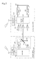
- FIG. 2 is a block diagram illustrating a system for directing a moving object according to a preferred embodiment of the present invention.
- the moving object directing system mainly includes a moving object directing unit 300 and a moving object 400.
- the moving object directing unit 300 basically includes directing signal transmission units 320 and 330 and a first RF communication unit 310.
- the directing signal transmission units 320 and 330 generate a first signal for directing the moving object 400, and output the first signal to the moving object 400.
- the directing signal transmission units 320 and 330 Upon receiving a response signal indicating successful reception of the first signal from the moving object 400, the directing signal transmission units 320 and 330 generate a second signal for directing the moving object 400 to direct the moving object 400 to a target location (e.g., a docking location of a charging device), and output the second signal to the moving object 400.
- a target location e.g., a docking location of a charging device
- the first RF communication unit 310 receives a signal indicating successful reception of the second signal for directing the moving object 400.
- the moving object directing unit 300 may be implemented with an additional module independent of the charging device.
- the moving object directing unit 300 may be integrated with the charging device required for charging the battery of the moving object 400.
- the moving object directing unit 300 includes the first RF communication unit 310 for communicating with the moving object 400 to inform the moving object 400 of the successful reception of the moving object directing signal.
- the moving object directing unit 300 further includes moving-object directing signal generators 332 and 333 acting as transmitters of the directing signal, a reflective mirror 334, a mirror rotation unit 335, and a controller 320.
- the moving-object directing signal generators 332 and 333 generate moving-object directing signals according to a control signal of the controller 320, and output the moving-object directing signals.
- the moving-object directing signal generators 332 and 333 can be implemented with an amplifier 332 for amplifying a signal and an infrared transmitter equipped with an infrared LED (Light Emitting Diode) 333. Therefore, the above-mentioned moving-object directing signal corresponds to an infrared beam for directing the moving object, and includes specific information required for directing the moving object. A detailed description of the moving-object directing signal will be described at a later time.
- the reflective mirror 334 reflects the moving-object directing signals generated from the moving object directing signal generators 332 and 333, and rotates by a rotation unit 335 (i.e., a motor) driven by the controller 320 by 360 degrees (i.e., 360°).
- a rotation unit 335 i.e., a motor driven by the controller 320 by 360 degrees (i.e., 360°).
- the moving object directing signals generated from the moving object directing signal generators 332 and 333 may be emitted 360° in all directions by the reflective mirror 334 and the rotation unit 335.
- the controller 320 controls operations of the moving-object directing unit 300 on the basis of control program data stored in an internal memory. For example, the controller 320 controls the moving object directing signal generation and a rotation angle of the reflective mirror 334, generates moving-object directing signals, and sequentially outputs the moving-object directing signals 360° in all directions.
- the controller 320 Upon receiving a signal indicating successful reception of the moving object directing signal from the first RF communication unit 310, the controller 320 stops the swing of the reflective mirror 334, and generates a moving-object directing signal corresponding to a rotation angle of the reflective mirror 334, such that it performs tracking the moving object 400 until reaching the target location.
- the above-mentioned reflective-mirror rotation angle information may be equal to moving-object directing information.
- the above-mentioned reflective-mirror rotation angle information may be defined as an offset angle of the moving object 400 on the basis of the target location (e.g., a docking location of the charging device).
- the moving object 400 receives the moving-object directing signal from the moving-object directing unit 300, and moves to a target location according to the moving-object directing information contained in the received signal.
- the moving object 400 includes a receiver 460 for receiving the moving object directing signal, as shown in FIG. 2.
- the receiver 460 can be implemented with an infrared receiver including both an infrared light-receiving unit 461 and an amplifier 462 for signal amplification.
- a plurality of receivers 460 may be used to enhance a receiving rate of the moving-object directing signal and a tracking performance as necessary.
- the controller 420 of the moving object 420 controls the wheel driving to receive the moving-object directing signal via a center infrared receiver from among the infrared receivers.
- the moving object 400 further includes a second RF communication unit 410 to communicate with the moving-object directing unit 300.
- the controller 420 of the moving object 400 can transmit a signal indicating successful reception of the moving-object directing signal to the moving-object directing unit 300 via the second RF communication unit 410.
- the controller 420 of the moving object 400 controls overall operations of the moving object 400 on the basis of control program data stored in the internal memory. For example, upon receiving the moving-object directing signal from the receiver 420, the controller 420 transmits a signal indicating successful reception of the moving-object directing signal to the moving-object directing unit 300 via the second RF communication unit 410, and controls the wheel driving according to directing information contained in the moving object directing signal transmitted from the moving-object directing unit 300.
- the moving object 400 further includes a sensor unit composed of a plurality of sensors capable of detecting a cliff (or drop), pressure, and an obstacle in the same manner as in a general cleaning robot. And, the moving object 400 further includes a wheel-motor drive 430, a wheel motor 440, and a rotation-amount detector 450, such that it can move by operations of the above-mentioned components 430, 440, and 450.
- the wheel-motor drive 430 drives a wheel motor M upon receiving a drive control signal from the controller 420.
- the rotation-amount detector 450 acting as an encoder connected to left and right wheels detects an amount of rotation of the left and right wheels, calculates rotation number data corresponding to the detected rotation amount, and transmits the calculated rotation number data to the controller 420.
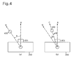
- FIG. 4 is a conceptual diagram illustrating operations of a system for directing a moving object according to the present invention.
- a reference number 300 is indicative of a charging device acting as a moving-object directing unit.
- a charging port 301 is located at the center of a lateral side of the charging device.
- a moving-object directing signal generator, a reflective mirror, and a reflective-mirror rotation unit are placed on the charging device, such that the moving-object directing signal may be emitted 360° in all directions.
- the docking location and the moving-object directing signal generator are located at an A axis.
- the A axis may be set to a target location of the moving object 400.
- the moving-object directing unit 300 must firstly detect the location of the moving object 400.
- the controller 320 of the moving-object directing 300 generates a control code capable of firstly generating the moving-object directing signal, and outputs the control code to the moving-object directing generators 332 and 333.
- the moving-object directing generators 332 and 333 generate the moving-object directing signal according to the control code, and forwardly transmit the moving-object directing signal via the reflective mirror 334.
- the controller 320 If the controller 320 does not receive the signal indicating successful reception of the moving-object directing signal via the first RF communication unit 310 after transmitting the moving-object directing signal, the controller 320 rotates the reflective mirror 334 by a predetermined angle by controlling the reflective-mirror rotation unit 335, and at the same time moves the reflective mirror 334. If the controller 320 re-generates a control code capable of generating the moving-object directing signal, a moving-object directing signal corresponding to the control code is emitted in another direction different from a previous direction.
- the controller 320 controls the moving-object directing signal generation simultaneously with rotating the reflective mirror 334, the moving-object directing signal is emitted 360° in all directions.
- the controller 420 of the moving object 400 receives a moving object directing signal via the receiver 460 such as an infrared receiver, it transmits specific information indicating successful reception of the moving- object directing signal to the moving-object directing unit 300 via the second RF communication unit 410.
- a moving object directing signal via the receiver 460 such as an infrared receiver, it transmits specific information indicating successful reception of the moving- object directing signal to the moving-object directing unit 300 via the second RF communication unit 410.
- the controller 320 of the moving-object directing unit 300 receives a signal indicating successful reception of the moving-object directing signal via the first RF communication unit 310, while sequentially rotating the reflective mirror 334 and at the same time transmitting the moving object directing signal 360° in all directions, it is determined that the controller 320 of the moving-object directing unit 300 has detected the location of the moving object 400, such that it stops rotation of the reflective mirror 334.
- the controller 320 If the location of the moving object 400 has been completely detected as described above, the controller 320 generates a control code corresponding to rotation angle information of the reflective mirror 334, and outputs the control code to the moving-object directing signal generators 332 and 333, such that the moving-object directing signal corresponding to the rotation angle information of the reflective mirror 334 can be transmitted to the receiver 460 of the moving object 400.
- the controller 420 of the moving object 400 receives the moving-object directing signal via the receiver 460, demodulates the received moving-object directing signal, acquires rotation angle information of the reflective mirror, and controls the wheel driving according to the acquired rotation angle information, such that it can access the target location.
- the controller 420 of the moving object 400 acquires the reflective-mirror rotation angle information value ⁇ .
- the controller 420 of the moving object 400 moves to a direction for reducing the reflective-mirror rotation angle information value ⁇ , as shown in FIG. 4(b).
- the controller 320 of the moving-object directing unit 300 can estimate a moving direction and a moving distance of the moving object 400. If the controller 320 rotates the reflective mirror 334 in the estimated direction to re-transmit the moving-object directing signal, and re-transmits the reflective-mirror rotation angle information according to the presence or absence of the received moving-object directing signal, the moving object 400 can reach the target location A by repetition of the above-mentioned operations of the controller 320.
- the controller 320 of the moving-object directing unit 300 continuously transmits the moving object directing signal on the condition that the reflective mirror 334 is fixed at a specific location.
- the controller 420 of the moving object 400 controls the wheel driving to receive the moving-object directing signal via the receiver located at the center part from among several receivers 460, the moving object 400 can be rapidly and correctly directed to the charging port 301 along the A axis serving as the target location.
- the moving object directing system can easily direct the moving object 400 to the target location such as the charging device without using several communication modules such as Beacons.
- the moving object directing system sequentially rotates the reflective mirror 334 and transmits the moving-object directing signal 360° in all directions
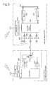
- the moving-object directing system may also be implemented by rotation of the infrared LED 333 corresponding to the moving object directing signal generator as shown in FIG. 3.
- the moving object directing signal generated from the infrared LED 333 can be rotated-outputted 360° in all directions according to the rotation of the motor.
- FIG. 3 is a block diagram illustrating a system for directing a moving object according to another preferred embodiment of the present invention.
- the moving-object directing unit 300 of FIG. 3 receives a signal indicating successful reception of the moving-object directing signal via the first RF communication unit 310, it generates a moving-object directing signal corresponding to the rotation angle information of the moving-object directing signal generator 335.
- the moving object 400 having received the moving-object directing signal corresponding to the rotation angle information of the moving-object directing signal generator 335, can be directed to the target location A in the same manner as in FIG. 2, and can also be directed to the charging port 301 along the target location A.
- the moving-object directing system can direct a moving object (e.g., a mobile robot) to a target location on the basis of moving-object directing information, which is transmitted in real time from a moving-object directing unit (i.e., a charging device), such that a low-priced system capable of moving the moving object to the target location without using additional modules such as Beacons can be implemented.
- a moving object e.g., a mobile robot
- a moving-object directing unit i.e., a charging device
- the moving-object directing system corrects a moving locus of the moving object in real time, such that the moving object can be rapidly directed to the target location.
Landscapes
- Engineering & Computer Science (AREA)
- Physics & Mathematics (AREA)
- General Physics & Mathematics (AREA)
- Radar, Positioning & Navigation (AREA)
- Remote Sensing (AREA)
- Automation & Control Theory (AREA)
- Aviation & Aerospace Engineering (AREA)
- Electromagnetism (AREA)
- Control Of Position, Course, Altitude, Or Attitude Of Moving Bodies (AREA)
- Toys (AREA)
Abstract
Description
- The present invention relates to a system for directing a moving object, and more particularly to a system for directing a moving object such as a mobile robot to a charging device.
- Typically, a robot developed for industrial purposes is being widely used to achieve factory automation, and collects data or information on behalf of a human being under an extreme situation, which is unbearable for the human being.
- Recently, the above-mentioned robotics technologies have been used for space industries, and have been rapidly developed in various ways, resulting in the implementation of human-friendly household robots.
- The human-friendly household mobile robot uses a battery to guarantee mobility at any place. If a voltage charged in the battery is equal to or less than a predetermined voltage, the human-friendly household mobile robot is programmed to automatically return to a charging device, such that the battery is re-charged.
- In order to normally return the mobile robot to the charging device, there is a need for the mobile robot to recognize its own relative location with respect to the charging device.
- A representative technique for returning the mobile robot to the charging device is a method for employing output data of an encoder mounted to a moving wheel. This technique has a disadvantage in that it cannot compensate for errors caused by a slip or no-load rotation of the wheel, such that it is considered to be an undesirable method.
- FIG. 1 is a conceptual diagram illustrating a conventional system for estimating a relative location of a robot acting as a moving object.
- Referring to FIG. 1, the system includes a plurality of
Beacon modules 100 installed to many places of a room ceiling, such that it estimates a relative location of amobile robot 200. EachBeacon module 100 includes an ultrasound transmitter and a Radio Frequency (RF) receiver. - If the
mobile robot 200 equipped with an ultrasound receiver and an RF transmitter requests ultrasound generation from theBeacon module 100, theBeacon module 100 transmits an ultrasound signal to themobile robot 200 upon receipt of the request. Therefore, themobile robot 200 calculates an arrival time of the ultrasound signal emitted from eachBeacon 100, such that it can calculate a distance from themobile robot 200 to eachBeacon 100. And, themobile robot 200 estimates its relative location, such that it can return to the charging device. - However, the above-mentioned system for employing the Beacon has a disadvantage in that a plurality of Beacons must be installed to many places of a room ceiling, such that the costs of implementing the system are unavoidably increased due to the use of many Beacons.
- It is an object of the invention to provide a moving object directing system for minimizing the costs of system implementation, and at the same time directing a moving object to a charging device without using additional modules.
- It is another object of the present invention to provide a moving object directing system for correcting a moving locus of a moving object in real time, and rapidly directing the moving object to a target location.
- In accordance with the present invention, the above and other objects can be accomplished by the provision of a moving-object directing system for directing a moving object to a target location comprising: a moving-object directing unit including: a directing signal transmitter for generating a first moving-object directing signal, sequentially transmitting the first moving-object directing signal 360° in all directions, generating a second moving-object directing signal corresponding to directing information for directing the moving object to the target location upon receiving a signal indicating successful reception of the first moving-object directing signal, and transmitting the second moving-object directing signal, and a first RF (Radio Frequency) communication unit for receiving a signal indicating successful reception of the moving-object directing signal; and the moving object including: a second RF communication unit for wirelessly transmitting a signal indicating successful reception of the moving object directing signal to the moving object directing unit, and a controller for controlling operations of a wheel according to directing information of the received moving-object directing signal.
- Therefore, the moving-object directing system according to the present invention can direct a moving object (e.g., a mobile robot) to a target location on the basis of moving-object directing information, which is transmitted in real time from a moving-object directing unit (i.e., a charging device), such that a low-priced system capable of moving the moving object to the target location without using additional modules such as Beacons can be implemented.
- The above and other objects, features and other advantages of the present invention will be more clearly understood from the following detailed description taken in conjunction with the accompanying drawings, in which:
- FIG. 1 is a conceptual diagram illustrating a conventional system for estimating a relative location of a mobile robot acting as a moving object;
- FIG. 2 is a block diagram illustrating a system for directing a moving object according to a preferred embodiment of the present invention;
- FIG. 3 is a block diagram illustrating a system for directing a moving object according to another preferred embodiment of the present invention; and
- FIG. 4 is a conceptual diagram illustrating operations of a system for directing a moving object according to the present invention.
- Now, preferred embodiments of the present invention will be described in detail with reference to the annexed drawings. In the drawings, the same or similar elements are denoted by the same reference numerals even though they are depicted in different drawings. In the following description, a detailed description of known functions and configurations incorporated herein will be omitted when it may make the subject matter of the present invention rather unclear.
- Prior to describing the present invention, it should be noted that a term "moving object" is indicative of a mobile robot such as a cleaning- or household- robot. The mobile robot is movable by wheels, but may be an exemplary mobile robot based on joint mechanism as necessary.
- FIG. 2 is a block diagram illustrating a system for directing a moving object according to a preferred embodiment of the present invention.
- Referring to FIG. 2, the moving object directing system mainly includes a moving
object directing unit 300 and amoving object 400. - The moving
object directing unit 300 basically includes directingsignal transmission units RF communication unit 310. - The directing
signal transmission units moving object 400, and output the first signal to themoving object 400. Upon receiving a response signal indicating successful reception of the first signal from themoving object 400, the directingsignal transmission units moving object 400 to direct themoving object 400 to a target location (e.g., a docking location of a charging device), and output the second signal to themoving object 400. - The first
RF communication unit 310 receives a signal indicating successful reception of the second signal for directing themoving object 400. - The moving
object directing unit 300 may be implemented with an additional module independent of the charging device. Preferably, the movingobject directing unit 300 may be integrated with the charging device required for charging the battery of themoving object 400. - A detailed description of the above-mentioned moving
object directing unit 300 will hereinafter be described with reference to FIG. 2. - Referring to FIG. 2, the moving
object directing unit 300 includes the firstRF communication unit 310 for communicating with themoving object 400 to inform themoving object 400 of the successful reception of the moving object directing signal. - The moving
object directing unit 300 further includes moving-objectdirecting signal generators reflective mirror 334, amirror rotation unit 335, and acontroller 320. - The moving-object directing
signal generators controller 320, and output the moving-object directing signals. - The moving-object
directing signal generators amplifier 332 for amplifying a signal and an infrared transmitter equipped with an infrared LED (Light Emitting Diode) 333. Therefore, the above-mentioned moving-object directing signal corresponds to an infrared beam for directing the moving object, and includes specific information required for directing the moving object. A detailed description of the moving-object directing signal will be described at a later time. - In the meantime, the
reflective mirror 334 reflects the moving-object directing signals generated from the moving object directingsignal generators controller 320 by 360 degrees (i.e., 360°). - In more detail, the moving object directing signals generated from the moving object directing
signal generators reflective mirror 334 and therotation unit 335. - The
controller 320 controls operations of the moving-object directingunit 300 on the basis of control program data stored in an internal memory. For example, thecontroller 320 controls the moving object directing signal generation and a rotation angle of thereflective mirror 334, generates moving-object directing signals, and sequentially outputs the moving-object directing signals 360° in all directions. - Upon receiving a signal indicating successful reception of the moving object directing signal from the first
RF communication unit 310, thecontroller 320 stops the swing of thereflective mirror 334, and generates a moving-object directing signal corresponding to a rotation angle of thereflective mirror 334, such that it performs tracking themoving object 400 until reaching the target location. - For reference, it is assumed that the above-mentioned reflective-mirror rotation angle information may be equal to moving-object directing information. And, the above-mentioned reflective-mirror rotation angle information may be defined as an offset angle of the
moving object 400 on the basis of the target location (e.g., a docking location of the charging device). - In the meantime, the
moving object 400 receives the moving-object directing signal from the moving-object directingunit 300, and moves to a target location according to the moving-object directing information contained in the received signal. - The
moving object 400 includes areceiver 460 for receiving the moving object directing signal, as shown in FIG. 2. Thereceiver 460 can be implemented with an infrared receiver including both an infrared light-receiving unit 461 and anamplifier 462 for signal amplification. A plurality ofreceivers 460 may be used to enhance a receiving rate of the moving-object directing signal and a tracking performance as necessary. - If a plurality of
receivers 460 are contained in the system, thecontroller 420 of themoving object 420 controls the wheel driving to receive the moving-object directing signal via a center infrared receiver from among the infrared receivers. - The
moving object 400 further includes a secondRF communication unit 410 to communicate with the moving-object directing unit 300. Thecontroller 420 of themoving object 400 can transmit a signal indicating successful reception of the moving-object directing signal to the moving-object directingunit 300 via the secondRF communication unit 410. - The
controller 420 of themoving object 400 controls overall operations of themoving object 400 on the basis of control program data stored in the internal memory. For example, upon receiving the moving-object directing signal from thereceiver 420, thecontroller 420 transmits a signal indicating successful reception of the moving-object directing signal to the moving-object directingunit 300 via the secondRF communication unit 410, and controls the wheel driving according to directing information contained in the moving object directing signal transmitted from the moving-object directing unit 300. - For reference, the
moving object 400 further includes a sensor unit composed of a plurality of sensors capable of detecting a cliff (or drop), pressure, and an obstacle in the same manner as in a general cleaning robot. And, themoving object 400 further includes a wheel-motor drive 430, awheel motor 440, and a rotation-amount detector 450, such that it can move by operations of the above-mentionedcomponents - The wheel-
motor drive 430 drives a wheel motor M upon receiving a drive control signal from thecontroller 420. The rotation-amount detector 450 acting as an encoder connected to left and right wheels detects an amount of rotation of the left and right wheels, calculates rotation number data corresponding to the detected rotation amount, and transmits the calculated rotation number data to thecontroller 420. - Operations of the above-mentioned moving object directing system will hereinafter be described with reference to FIG. 4.
- FIG. 4 is a conceptual diagram illustrating operations of a system for directing a moving object according to the present invention.
- A
reference number 300 is indicative of a charging device acting as a moving-object directing unit. A chargingport 301 is located at the center of a lateral side of the charging device. A moving-object directing signal generator, a reflective mirror, and a reflective-mirror rotation unit are placed on the charging device, such that the moving-object directing signal may be emitted 360° in all directions. - For reference, provided that a docking location is placed at the center part of the charging
port 301 is, the docking location and the moving-object directing signal generator are located at an A axis. In this case, the A axis may be set to a target location of the movingobject 400. - As shown in FIG. 4(a), if the system desires to move the moving
object 400 to the charging-device docking location on the condition that the moving object has been placed on a B axis, the moving-object directing unit 300 must firstly detect the location of the movingobject 400. - The
controller 320 of the moving-object directing 300 generates a control code capable of firstly generating the moving-object directing signal, and outputs the control code to the moving-object directing generators - The moving-
object directing generators reflective mirror 334. - If the
controller 320 does not receive the signal indicating successful reception of the moving-object directing signal via the firstRF communication unit 310 after transmitting the moving-object directing signal, thecontroller 320 rotates thereflective mirror 334 by a predetermined angle by controlling the reflective-mirror rotation unit 335, and at the same time moves thereflective mirror 334. If thecontroller 320 re-generates a control code capable of generating the moving-object directing signal, a moving-object directing signal corresponding to the control code is emitted in another direction different from a previous direction. - Therefore, if the
controller 320 controls the moving-object directing signal generation simultaneously with rotating thereflective mirror 334, the moving-object directing signal is emitted 360° in all directions. - For reference, if the
controller 420 of the movingobject 400 receives a moving object directing signal via thereceiver 460 such as an infrared receiver, it transmits specific information indicating successful reception of the moving- object directing signal to the moving-object directing unit 300 via the secondRF communication unit 410. - Therefore, if the
controller 320 of the moving-object directing unit 300 receives a signal indicating successful reception of the moving-object directing signal via the firstRF communication unit 310, while sequentially rotating thereflective mirror 334 and at the same time transmitting the moving object directing signal 360° in all directions, it is determined that thecontroller 320 of the moving-object directing unit 300 has detected the location of the movingobject 400, such that it stops rotation of thereflective mirror 334. - If the location of the moving
object 400 has been completely detected as described above, thecontroller 320 generates a control code corresponding to rotation angle information of thereflective mirror 334, and outputs the control code to the moving-objectdirecting signal generators reflective mirror 334 can be transmitted to thereceiver 460 of the movingobject 400. - Therefore, the
controller 420 of the movingobject 400 receives the moving-object directing signal via thereceiver 460, demodulates the received moving-object directing signal, acquires rotation angle information of the reflective mirror, and controls the wheel driving according to the acquired rotation angle information, such that it can access the target location. - For example, as shown in FIG. 4(a), if the moving
object 400 is located at a specific location offset by a predetermined angle α from the target location A, thecontroller 420 of the movingobject 400 acquires the reflective-mirror rotation angle information value α. - Therefore, the
controller 420 of the movingobject 400 moves to a direction for reducing the reflective-mirror rotation angle information value α, as shown in FIG. 4(b). - In this case, the
controller 320 of the moving-object directing unit 300 can estimate a moving direction and a moving distance of the movingobject 400. If thecontroller 320 rotates thereflective mirror 334 in the estimated direction to re-transmit the moving-object directing signal, and re-transmits the reflective-mirror rotation angle information according to the presence or absence of the received moving-object directing signal, the movingobject 400 can reach the target location A by repetition of the above-mentioned operations of thecontroller 320. - If the moving object reaches the target location A, the
controller 320 of the moving-object directing unit 300 continuously transmits the moving object directing signal on the condition that thereflective mirror 334 is fixed at a specific location. In this case, if thecontroller 420 of the movingobject 400 controls the wheel driving to receive the moving-object directing signal via the receiver located at the center part from amongseveral receivers 460, the movingobject 400 can be rapidly and correctly directed to the chargingport 301 along the A axis serving as the target location. - Therefore, the moving object directing system according to the present invention can easily direct the moving
object 400 to the target location such as the charging device without using several communication modules such as Beacons. - As described above, although the moving object directing system according to the present invention sequentially rotates the
reflective mirror 334 and transmits the moving-object directing signal 360° in all directions, the moving-object directing system may also be implemented by rotation of theinfrared LED 333 corresponding to the moving object directing signal generator as shown in FIG. 3. - In other words, if a
connector 336 coupled to theinfrared LED 333 acting as the moving object directing signal generator is connected to a rotation axis of the motor acting as therotation unit 335, the moving object directing signal generated from theinfrared LED 333 can be rotated-outputted 360° in all directions according to the rotation of the motor. - FIG. 3 is a block diagram illustrating a system for directing a moving object according to another preferred embodiment of the present invention.
- Unexplained reference numerals of FIG. 3 are identical with those of FIG. 2, such that a detailed description thereof will herein be omitted for the convenience of description. However, if the moving-
object directing unit 300 of FIG. 3 receives a signal indicating successful reception of the moving-object directing signal via the firstRF communication unit 310, it generates a moving-object directing signal corresponding to the rotation angle information of the moving-objectdirecting signal generator 335. - Therefore, the moving
object 400, having received the moving-object directing signal corresponding to the rotation angle information of the moving-objectdirecting signal generator 335, can be directed to the target location A in the same manner as in FIG. 2, and can also be directed to the chargingport 301 along the target location A. - As apparent from the above description, the moving-object directing system according to the present invention can direct a moving object (e.g., a mobile robot) to a target location on the basis of moving-object directing information, which is transmitted in real time from a moving-object directing unit (i.e., a charging device), such that a low-priced system capable of moving the moving object to the target location without using additional modules such as Beacons can be implemented.
- In addition, the moving-object directing system according to the present invention corrects a moving locus of the moving object in real time, such that the moving object can be rapidly directed to the target location.
Claims (12)
- A moving-object directing system for directing a moving object to a target location comprising:a moving-object directing unit including:a directing signal transmitter for generating a first moving-object directing signal, sequentially transmitting the first moving-object directing signal 360° in all directions, generating a second moving-object directing signal corresponding to directing information for directing the moving object to the target location upon receiving a signal indicating successful reception of the first moving-object directing signal, and transmitting the second moving-object directing signal, anda first RF (Radio Frequency) communication unit for receiving a signal indicating successful reception of the moving-object directing signal; andthe moving object including:a second RF communication unit for wirelessly transmitting a signal indicating successful reception of the moving object directing signal to the moving object directing unit, anda controller for controlling operations of a wheel according to directing information of the received moving-object directing signal.
- The system according to claim 1, wherein the directing signal transmitter includes:a moving-object directing signal generator;a reflective mirror for reflecting the moving-object directing signal generated from the generator;a rotation unit for rotating the reflective mirror; anda controller for controlling the moving-object directing signal, and at the same time controlling a rotation angle of the reflective mirror.
- The system according to claim 1, wherein the directing signal transmitter includes:a moving-object directing signal generator;a rotation unit for rotating the moving-object directing signal generator; anda controller for controls generation of the moving-object directing signal, and at the same time controlling a rotation angle of the rotation unit.
- The system according to any one of claims 2 and 3, wherein the moving-object directing signal generator is an infrared transmitter.
- The system according to any one of claims 2 and 3, wherein:upon receiving the signal indicating successful reception of the moving-object directing signal via the first RF communication unit, the controller stops operations of the rotation unit, and controls generation of a moving-object directing signal corresponding to the rotation angle information.
- The system according to claim 5, wherein the rotation angle information is indicative of an offset angle of the moving object on the basis of the target location.
- The system according to claim 5, wherein the controller of the moving object controls wheel operations in a direction for reducing the rotation angle information.
- The system according to any one of claims 2 and 3, wherein:if the controller does not receive the signal indicating successful reception of the moving object directing signal via the first RF communication unit, the controller rotates the rotation unit by a predetermined angle.
- The system according to any of claims 1 to 8, wherein the moving object includes:a wheel motor for rotating a wheel;a wheel-motor drive for driving the wheel motor; anda rotation-amount detector for detecting a rotation amount of the wheel,wherein the controller of the moving object controls the wheel according to the received moving-object directing information and a signal of the rotation-amount detector.
- The system according to claim 9, wherein the moving object further includes a sensor unit composed of sensors capable of detecting an obstacle, pressure, and a cliff (or drop).
- The system according to any of claims 1 to 10, wherein the moving object is a cleaning robot, and the moving-object directing unit is a charging unit for charging the cleaning robot with electricity.
- The system according to any of claims 1 to 11, wherein:the moving object includes a plurality of receivers for receiving the moving-object directing signal, andthe controller controls the wheel to receive the moving object directing signal via a center receiver from among the receivers.
Applications Claiming Priority (1)
| Application Number | Priority Date | Filing Date | Title |
|---|---|---|---|
| KR1020050066971A KR100704485B1 (en) | 2005-07-22 | 2005-07-22 | System for lead a robot into the target point |
Publications (3)
| Publication Number | Publication Date |
|---|---|
| EP1746477A2 true EP1746477A2 (en) | 2007-01-24 |
| EP1746477A3 EP1746477A3 (en) | 2010-08-04 |
| EP1746477B1 EP1746477B1 (en) | 2011-09-14 |
Family
ID=37199034
Family Applications (1)
| Application Number | Title | Priority Date | Filing Date |
|---|---|---|---|
| EP06015156A Ceased EP1746477B1 (en) | 2005-07-22 | 2006-07-20 | System for directing a moving object |
Country Status (5)
| Country | Link |
|---|---|
| US (1) | US7365512B2 (en) |
| EP (1) | EP1746477B1 (en) |
| KR (1) | KR100704485B1 (en) |
| CN (1) | CN100474196C (en) |
| RU (1) | RU2323465C1 (en) |
Cited By (5)
| Publication number | Priority date | Publication date | Assignee | Title |
|---|---|---|---|---|
| RU2601284C1 (en) * | 2015-08-25 | 2016-10-27 | Виктор Андреевич Павлов | Method for adaptive spectral selection of targets |
| WO2017114571A1 (en) * | 2015-12-30 | 2017-07-06 | Telecom Italia S.P.A. | Docking system and method for charging a mobile robot |
| AT15526U1 (en) * | 2016-06-07 | 2017-11-15 | Tridonic Gmbh & Co Kg | Sensor arrangement for the optimized navigation of a cleaning robot |
| EP3254593A1 (en) * | 2016-06-07 | 2017-12-13 | Tridonic GmbH & Co. KG | Sensor assembly for the optimized navigation of a mobile robbot unit |
| GB2597656A (en) * | 2020-07-21 | 2022-02-09 | Nokia Technologies Oy | Apparatus, methods and computer programs for locating mobile devices |
Families Citing this family (5)
| Publication number | Priority date | Publication date | Assignee | Title |
|---|---|---|---|---|
| CN101847011B (en) * | 2010-03-31 | 2012-06-13 | 深圳市银星智能科技股份有限公司 | Portable area positioning and covering method for mobile robot |
| RU2480780C1 (en) * | 2011-10-28 | 2013-04-27 | Государственное образовательное учреждение высшего профессионального образования "Военная академия войсковой противовоздушной обороны Вооруженных Сил Российской Федерации" Министерства обороны Российской Федерации | Method of detecting point thermal objects on masking atmospheric background |
| CN104117987B (en) * | 2013-04-26 | 2017-05-10 | 恩斯迈电子(深圳)有限公司 | Mobile robot |
| DE102013209024A1 (en) * | 2013-05-15 | 2014-11-20 | Robert Bosch Gmbh | Method for detecting objects by adaptive beamforming |
| KR20220046190A (en) * | 2020-10-07 | 2022-04-14 | 삼성전자주식회사 | Robot, charghing station and robot charghing system comprising the same |
Citations (5)
| Publication number | Priority date | Publication date | Assignee | Title |
|---|---|---|---|---|
| US4679152A (en) | 1985-02-20 | 1987-07-07 | Heath Company | Navigation system and method for a mobile robot |
| GB2357337A (en) | 1999-09-29 | 2001-06-20 | Vi & T Group Inc | Automated object following system |
| US20040178767A1 (en) | 2003-03-14 | 2004-09-16 | Lg Electronics Inc. | Automatic charging system and method of robot cleaner |
| US20050021178A1 (en) | 2003-07-23 | 2005-01-27 | Se-Wan Kim | Method and apparatus for detecting position of mobile robot |
| US20050137748A1 (en) | 2003-12-22 | 2005-06-23 | Se-Wan Kim | Apparatus and method for detecting position of mobile robot |
Family Cites Families (7)
| Publication number | Priority date | Publication date | Assignee | Title |
|---|---|---|---|---|
| US4964265A (en) * | 1989-09-11 | 1990-10-23 | Young Carl W | Remotely controlled lawn mower |
| US5711388A (en) * | 1995-07-20 | 1998-01-27 | Golfpro International, Inc. | Robotic golf caddy apparatus and method |
| US5646630A (en) * | 1996-05-20 | 1997-07-08 | Trimble Navigation Limited | Network of equivalent ground transmitters |
| EP1060091B1 (en) * | 1998-01-28 | 2004-01-14 | O.M.G. S.R.L. | Automatic cart for transporting golf clubs or other objects and accessories |
| US6640164B1 (en) * | 2001-08-28 | 2003-10-28 | Itt Manufacturing Enterprises, Inc. | Methods and systems for remote control of self-propelled vehicles |
| KR100946935B1 (en) * | 2003-06-02 | 2010-03-09 | 삼성전자주식회사 | Apparatus for locating of mobile vehicle |
| US7332890B2 (en) * | 2004-01-21 | 2008-02-19 | Irobot Corporation | Autonomous robot auto-docking and energy management systems and methods |
-
2005
- 2005-07-22 KR KR1020050066971A patent/KR100704485B1/en not_active IP Right Cessation
-
2006
- 2006-07-20 US US11/489,510 patent/US7365512B2/en not_active Expired - Fee Related
- 2006-07-20 EP EP06015156A patent/EP1746477B1/en not_active Ceased
- 2006-07-21 CN CNB2006101078085A patent/CN100474196C/en not_active Expired - Fee Related
- 2006-07-21 RU RU2006126758/02A patent/RU2323465C1/en not_active IP Right Cessation
Patent Citations (5)
| Publication number | Priority date | Publication date | Assignee | Title |
|---|---|---|---|---|
| US4679152A (en) | 1985-02-20 | 1987-07-07 | Heath Company | Navigation system and method for a mobile robot |
| GB2357337A (en) | 1999-09-29 | 2001-06-20 | Vi & T Group Inc | Automated object following system |
| US20040178767A1 (en) | 2003-03-14 | 2004-09-16 | Lg Electronics Inc. | Automatic charging system and method of robot cleaner |
| US20050021178A1 (en) | 2003-07-23 | 2005-01-27 | Se-Wan Kim | Method and apparatus for detecting position of mobile robot |
| US20050137748A1 (en) | 2003-12-22 | 2005-06-23 | Se-Wan Kim | Apparatus and method for detecting position of mobile robot |
Cited By (6)
| Publication number | Priority date | Publication date | Assignee | Title |
|---|---|---|---|---|
| RU2601284C1 (en) * | 2015-08-25 | 2016-10-27 | Виктор Андреевич Павлов | Method for adaptive spectral selection of targets |
| WO2017114571A1 (en) * | 2015-12-30 | 2017-07-06 | Telecom Italia S.P.A. | Docking system and method for charging a mobile robot |
| US10775803B2 (en) | 2015-12-30 | 2020-09-15 | Telecom Italia S.P.A. | Docking system and method for charging a mobile robot |
| AT15526U1 (en) * | 2016-06-07 | 2017-11-15 | Tridonic Gmbh & Co Kg | Sensor arrangement for the optimized navigation of a cleaning robot |
| EP3254593A1 (en) * | 2016-06-07 | 2017-12-13 | Tridonic GmbH & Co. KG | Sensor assembly for the optimized navigation of a mobile robbot unit |
| GB2597656A (en) * | 2020-07-21 | 2022-02-09 | Nokia Technologies Oy | Apparatus, methods and computer programs for locating mobile devices |
Also Published As
| Publication number | Publication date |
|---|---|
| RU2323465C1 (en) | 2008-04-27 |
| US7365512B2 (en) | 2008-04-29 |
| EP1746477B1 (en) | 2011-09-14 |
| KR20070012117A (en) | 2007-01-25 |
| CN1900868A (en) | 2007-01-24 |
| EP1746477A3 (en) | 2010-08-04 |
| CN100474196C (en) | 2009-04-01 |
| US20070018081A1 (en) | 2007-01-25 |
| RU2006126758A (en) | 2008-01-27 |
| KR100704485B1 (en) | 2007-04-10 |
Similar Documents
| Publication | Publication Date | Title |
|---|---|---|
| EP1746477B1 (en) | System for directing a moving object | |
| JP6662454B2 (en) | Moving object guidance system, moving object, guidance device, and computer program | |
| JP6973393B2 (en) | Mobile guidance systems, mobiles, guidance devices and computer programs | |
| US6504610B1 (en) | Method and system for positioning an autonomous mobile unit for docking | |
| RU2419104C2 (en) | Method and system to locate moving transport facilities | |
| US7860608B2 (en) | Method and apparatus for generating and tracing cleaning trajectory of home cleaning robot | |
| KR101303911B1 (en) | user following robot | |
| WO2004025947A2 (en) | A navigational control system for a robotic device | |
| CN101109630A (en) | Beacon to measure distance, positioning system using the same, and method of measuring distance | |
| WO2020003304A1 (en) | A computerized system for guiding a mobile robot to a docking station and a method of using same | |
| ES2855102T3 (en) | Device and procedure for position determination | |
| WO2012107300A1 (en) | Location system for determining the position of an object | |
| US20040210346A1 (en) | Method and apparatus for allowing mobile robot to return to docking station | |
| DK2639790T3 (en) | Driverless vehicle with at least one ultrasonic sensor and method for its operation | |
| WO2019054206A1 (en) | Moving body guidance system | |
| KR100845528B1 (en) | Self-charge docking system and obstacle avoidance of a robot using anisotropic ultrasonic sensors | |
| JP3867334B2 (en) | Autonomous mobile robot for building | |
| Seki et al. | Autonomous/semi-autonomous navigation system of a wheelchair by active ultrasonic beacons | |
| CN107831759B (en) | Transport system with automatic binding function | |
| JP2006317161A (en) | Tracking system | |
| KR100757061B1 (en) | System for lead a robot into the target point | |
| CN212276270U (en) | Intelligent omnidirectional mobile robot and ultrasonic obstacle avoidance system and posture correction system thereof | |
| JPH0587792B2 (en) | ||
| KR100858276B1 (en) | Signal generation apparatus of deducting position | |
| EP0636902B1 (en) | Method for determining the position of a mobile vehicle within a limited area and device embodying said method |
Legal Events
| Date | Code | Title | Description |
|---|---|---|---|
| PUAI | Public reference made under article 153(3) epc to a published international application that has entered the european phase |
Free format text: ORIGINAL CODE: 0009012 |
|
| 17P | Request for examination filed |
Effective date: 20060818 |
|
| AK | Designated contracting states |
Kind code of ref document: A2 Designated state(s): AT BE BG CH CY CZ DE DK EE ES FI FR GB GR HU IE IS IT LI LT LU LV MC NL PL PT RO SE SI SK TR |
|
| AX | Request for extension of the european patent |
Extension state: AL BA HR MK YU |
|
| PUAL | Search report despatched |
Free format text: ORIGINAL CODE: 0009013 |
|
| AK | Designated contracting states |
Kind code of ref document: A3 Designated state(s): AT BE BG CH CY CZ DE DK EE ES FI FR GB GR HU IE IS IT LI LT LU LV MC NL PL PT RO SE SI SK TR |
|
| AX | Request for extension of the european patent |
Extension state: AL BA HR MK RS |
|
| RIC1 | Information provided on ipc code assigned before grant |
Ipc: G01S 3/782 20060101ALI20100629BHEP Ipc: G05D 1/02 20060101AFI20061107BHEP |
|
| GRAP | Despatch of communication of intention to grant a patent |
Free format text: ORIGINAL CODE: EPIDOSNIGR1 |
|
| AKX | Designation fees paid |
Designated state(s): DE GB |
|
| RIC1 | Information provided on ipc code assigned before grant |
Ipc: G01S 3/782 20060101ALI20110310BHEP Ipc: G05D 1/02 20060101AFI20110310BHEP |
|
| RTI1 | Title (correction) |
Free format text: SYSTEM FOR DIRECTING A MOVING OBJECT |
|
| GRAS | Grant fee paid |
Free format text: ORIGINAL CODE: EPIDOSNIGR3 |
|
| GRAA | (expected) grant |
Free format text: ORIGINAL CODE: 0009210 |
|
| AK | Designated contracting states |
Kind code of ref document: B1 Designated state(s): DE GB |
|
| REG | Reference to a national code |
Ref country code: GB Ref legal event code: FG4D |
|
| REG | Reference to a national code |
Ref country code: DE Ref legal event code: R096 Ref document number: 602006024332 Country of ref document: DE Effective date: 20111110 |
|
| PLBE | No opposition filed within time limit |
Free format text: ORIGINAL CODE: 0009261 |
|
| STAA | Information on the status of an ep patent application or granted ep patent |
Free format text: STATUS: NO OPPOSITION FILED WITHIN TIME LIMIT |
|
| 26N | No opposition filed |
Effective date: 20120615 |
|
| REG | Reference to a national code |
Ref country code: DE Ref legal event code: R097 Ref document number: 602006024332 Country of ref document: DE Effective date: 20120615 |
|
| PGFP | Annual fee paid to national office [announced via postgrant information from national office to epo] |
Ref country code: DE Payment date: 20180605 Year of fee payment: 13 Ref country code: GB Payment date: 20180606 Year of fee payment: 13 |
|
| REG | Reference to a national code |
Ref country code: DE Ref legal event code: R119 Ref document number: 602006024332 Country of ref document: DE |
|
| GBPC | Gb: european patent ceased through non-payment of renewal fee |
Effective date: 20190720 |
|
| PG25 | Lapsed in a contracting state [announced via postgrant information from national office to epo] |
Ref country code: DE Free format text: LAPSE BECAUSE OF NON-PAYMENT OF DUE FEES Effective date: 20200201 Ref country code: GB Free format text: LAPSE BECAUSE OF NON-PAYMENT OF DUE FEES Effective date: 20190720 |