EP1746396A1 - UV adjustable optical attenuator - Google Patents
UV adjustable optical attenuator Download PDFInfo
- Publication number
- EP1746396A1 EP1746396A1 EP06014356A EP06014356A EP1746396A1 EP 1746396 A1 EP1746396 A1 EP 1746396A1 EP 06014356 A EP06014356 A EP 06014356A EP 06014356 A EP06014356 A EP 06014356A EP 1746396 A1 EP1746396 A1 EP 1746396A1
- Authority
- EP
- European Patent Office
- Prior art keywords
- light
- light absorbing
- absorbing medium
- attenuation
- intensity
- Prior art date
- Legal status (The legal status is an assumption and is not a legal conclusion. Google has not performed a legal analysis and makes no representation as to the accuracy of the status listed.)
- Ceased
Links
- 230000003287 optical effect Effects 0.000 title claims abstract description 20
- 230000001419 dependent effect Effects 0.000 claims abstract description 25
- 238000010521 absorption reaction Methods 0.000 claims abstract description 23
- 239000012780 transparent material Substances 0.000 claims abstract description 22
- 230000008859 change Effects 0.000 claims abstract description 17
- 238000000034 method Methods 0.000 claims description 24
- 230000004044 response Effects 0.000 claims description 3
- 239000004593 Epoxy Substances 0.000 claims description 2
- 239000000843 powder Substances 0.000 claims description 2
- 230000008569 process Effects 0.000 description 14
- 238000010586 diagram Methods 0.000 description 8
- 239000000463 material Substances 0.000 description 7
- 238000005259 measurement Methods 0.000 description 6
- 230000031700 light absorption Effects 0.000 description 3
- 239000007787 solid Substances 0.000 description 3
- 239000007788 liquid Substances 0.000 description 2
- 238000004519 manufacturing process Methods 0.000 description 2
- 239000000203 mixture Substances 0.000 description 2
- 229920006397 acrylic thermoplastic Polymers 0.000 description 1
- 230000004075 alteration Effects 0.000 description 1
- 230000002238 attenuated effect Effects 0.000 description 1
- 238000001514 detection method Methods 0.000 description 1
- 238000001914 filtration Methods 0.000 description 1
- 239000004973 liquid crystal related substance Substances 0.000 description 1
- 229920003229 poly(methyl methacrylate) Polymers 0.000 description 1
- 230000002441 reversible effect Effects 0.000 description 1
- 230000035945 sensitivity Effects 0.000 description 1
- 230000003068 static effect Effects 0.000 description 1
- ISXSCDLOGDJUNJ-UHFFFAOYSA-N tert-butyl prop-2-enoate Chemical compound CC(C)(C)OC(=O)C=C ISXSCDLOGDJUNJ-UHFFFAOYSA-N 0.000 description 1
Images



Classifications
-
- G—PHYSICS
- G01—MEASURING; TESTING
- G01J—MEASUREMENT OF INTENSITY, VELOCITY, SPECTRAL CONTENT, POLARISATION, PHASE OR PULSE CHARACTERISTICS OF INFRARED, VISIBLE OR ULTRAVIOLET LIGHT; COLORIMETRY; RADIATION PYROMETRY
- G01J1/00—Photometry, e.g. photographic exposure meter
- G01J1/02—Details
- G01J1/04—Optical or mechanical part supplementary adjustable parts
-
- G—PHYSICS
- G01—MEASURING; TESTING
- G01J—MEASUREMENT OF INTENSITY, VELOCITY, SPECTRAL CONTENT, POLARISATION, PHASE OR PULSE CHARACTERISTICS OF INFRARED, VISIBLE OR ULTRAVIOLET LIGHT; COLORIMETRY; RADIATION PYROMETRY
- G01J1/00—Photometry, e.g. photographic exposure meter
- G01J1/02—Details
- G01J1/04—Optical or mechanical part supplementary adjustable parts
- G01J1/0407—Optical elements not provided otherwise, e.g. manifolds, windows, holograms, gratings
- G01J1/0418—Optical elements not provided otherwise, e.g. manifolds, windows, holograms, gratings using attenuators
-
- G—PHYSICS
- G02—OPTICS
- G02B—OPTICAL ELEMENTS, SYSTEMS OR APPARATUS
- G02B5/00—Optical elements other than lenses
- G02B5/20—Filters
- G02B5/22—Absorbing filters
- G02B5/23—Photochromic filters
-
- G—PHYSICS
- G02—OPTICS
- G02F—OPTICAL DEVICES OR ARRANGEMENTS FOR THE CONTROL OF LIGHT BY MODIFICATION OF THE OPTICAL PROPERTIES OF THE MEDIA OF THE ELEMENTS INVOLVED THEREIN; NON-LINEAR OPTICS; FREQUENCY-CHANGING OF LIGHT; OPTICAL LOGIC ELEMENTS; OPTICAL ANALOGUE/DIGITAL CONVERTERS
- G02F1/00—Devices or arrangements for the control of the intensity, colour, phase, polarisation or direction of light arriving from an independent light source, e.g. switching, gating or modulating; Non-linear optics
- G02F1/01—Devices or arrangements for the control of the intensity, colour, phase, polarisation or direction of light arriving from an independent light source, e.g. switching, gating or modulating; Non-linear optics for the control of the intensity, phase, polarisation or colour
- G02F1/0126—Opto-optical modulation, i.e. control of one light beam by another light beam, not otherwise provided for in this subclass
-
- G—PHYSICS
- G01—MEASURING; TESTING
- G01J—MEASUREMENT OF INTENSITY, VELOCITY, SPECTRAL CONTENT, POLARISATION, PHASE OR PULSE CHARACTERISTICS OF INFRARED, VISIBLE OR ULTRAVIOLET LIGHT; COLORIMETRY; RADIATION PYROMETRY
- G01J1/00—Photometry, e.g. photographic exposure meter
- G01J1/02—Details
- G01J1/04—Optical or mechanical part supplementary adjustable parts
- G01J1/0488—Optical or mechanical part supplementary adjustable parts with spectral filtering
-
- G—PHYSICS
- G02—OPTICS
- G02F—OPTICAL DEVICES OR ARRANGEMENTS FOR THE CONTROL OF LIGHT BY MODIFICATION OF THE OPTICAL PROPERTIES OF THE MEDIA OF THE ELEMENTS INVOLVED THEREIN; NON-LINEAR OPTICS; FREQUENCY-CHANGING OF LIGHT; OPTICAL LOGIC ELEMENTS; OPTICAL ANALOGUE/DIGITAL CONVERTERS
- G02F2201/00—Constructional arrangements not provided for in groups G02F1/00 - G02F7/00
- G02F2201/08—Constructional arrangements not provided for in groups G02F1/00 - G02F7/00 light absorbing layer
- G02F2201/086—UV absorbing
-
- G—PHYSICS
- G02—OPTICS
- G02F—OPTICAL DEVICES OR ARRANGEMENTS FOR THE CONTROL OF LIGHT BY MODIFICATION OF THE OPTICAL PROPERTIES OF THE MEDIA OF THE ELEMENTS INVOLVED THEREIN; NON-LINEAR OPTICS; FREQUENCY-CHANGING OF LIGHT; OPTICAL LOGIC ELEMENTS; OPTICAL ANALOGUE/DIGITAL CONVERTERS
- G02F2203/00—Function characteristic
- G02F2203/48—Variable attenuator
Definitions
- One way to reduce the intensity of a light beam is to pass the light beam through a light absorbing medium.
- the intensity of the exiting light beam can be controlled by selecting a light absorbing medium with the desired attenuation.
- Light absorbing mediums having fixed attenuation are well known in the optics field.
- optical systems such as lasers, light emitting diodes (LEDs), liquid crystal displays (LCDs), and charged coupled devices (CCDs) often have dynamic and/or unpredictable optical characteristics.
- the dynamic and/or unpredictable nature of many optical systems can make it difficult to effectively control the optical systems using light absorbing mediums with fixed attenuation properties. For example, as the output characteristic of an LED or LCD panel degrades, an installed light absorbing medium with a fixed attenuation may no longer provide the ideal attenuation for the system.
- light absorbing mediums with different attenuation properties may need to be matched with LEDs on a per-LED basis to produce a batch of LED based products with the same optical characteristics.
- An optical element includes a light absorbing medium formed of a transparent material and light absorbing elements encapsulated within the transparent material.
- the light absorbing elements have an ultraviolet (UV) light-dependent absorption characteristic and UV light is applied to the light absorbing medium to change the attenuation of the light absorbing medium to a desired attenuation.
- UV light is applied to the light absorbing medium to change the attenuation of the light absorbing medium to a desired attenuation.
- the application of UV light to the light absorbing medium causes the light absorbing elements encapsulated within the light absorbing medium to degrade such that the amount of light absorbed by the light absorbing medium is reduced. Reducing the amount of light that is absorbed effectively reduces the attenuation of the light absorbing medium.
- UV light is applied to the light absorbing medium in a controlled manner to change the attenuation of the light absorbing medium from an initial attenuation to the desired attenuation.
- a system for changing the attenuation of a light absorbing medium from an initial attenuation to the desired attenuation includes a light source, a light detector, a controller, and a UV light source.
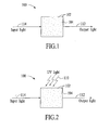
- Fig. 1 depicts a light absorbing medium that has a UV light-dependent absorption characteristic.
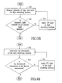
- Fig. 2 depicts the application of UV light to the light absorbing medium of Fig. 1 to change the attenuation of the light absorbing medium to a desired attenuation.
- Fig. 3A depicts an embodiment of a system that can be used to change the attenuation of a light absorbing medium from an initial attenuation to a desired attenuation.
- Fig. 3B depicts a process flow diagram of a method for setting the attenuation of a light absorbing medium.
- Fig. 4A depicts another embodiment of a system that can be used to change the attenuation of a light absorbing medium from an initial attenuation to a desired attenuation.
- Fig. 4B depicts a process flow diagram of a method for setting the attenuation of a light absorbing medium.
- Fig. 5 depicts a light absorbing medium with a UV light-dependent light absorption characteristic that is used in conjunction with a laser.
- Fig. 6 depicts a light absorbing medium with a UV light-dependent absorption characteristic that is used in conjunction with an LED.
- Fig. 7 depicts a light absorbing medium with a UV light-dependent absorption characteristic that is used in conjunction with an LED.
- Fig. 8 depicts a light absorbing medium with a UV light-dependent absorption characteristic that is used in conjunction with an LCD panel.
- Fig. 9 depicts a light absorbing medium with a UV light-dependent absorption characteristic that is used in conjunction with a color-specific set of sensors of a CCD sensor array.
- Fig. 10 depicts a light absorbing medium with a UV light-dependent absorption characteristic that is formed on the surface of an optical element such as a lens.
- Fig. 11 is a process flow diagram of a method for attenuating light in accordance with an embodiment of the invention.
- Fig. 12 is a process flow diagram of a method for producing a light absorbing medium having a desired attenuation in accordance with an embodiment of the invention.
- Fig. 1 depicts a light absorbing medium 100 that has a UV light-dependent absorption characteristic.
- the light absorbing medium can be formed by mixing light absorbing elements 102 into a transparent material 104 while the transparent material is in a liquid state. The mixture of the transparent material and the light absorbing elements is then cured into a solid state to form the light absorbing medium.
- the transparent material that is used to form the light absorbing medium can be any transparent material that can be mixed with light absorbing elements and then cured into a solid state.
- Example transparent materials include acrylics and epoxy.
- the terms "transparent" and “transparent material” mean a material that is pervious to light or a material through which light can pass.
- Transparent and “transparent material” does not necessarily mean that light passes through the material such that objects or images can be seen as if there is no intervening material. That is, a material is considered transparent even if there is some diffusing of light within the material. As used herein, a transparent material includes a translucent material.
- the light absorbing elements 102 that are encapsulated within the transparent material 104 have a characteristic that is sensitive to UV light.
- the light absorbing elements have an optical absorption characteristic that is permanently altered as a result of exposure to UV light.
- Examples of light absorbing elements include ink and colored powder dye.
- the sensitivity of the light absorbing elements to UV light causes the light absorbing medium 100 to exhibit a UV light-dependent absorption characteristic. Changes in the absorption characteristic of the light absorbing medium are manifested as different attenuation levels when light is passed through the light absorbing medium. In an embodiment, the changes in the absorption characteristic of the light absorbing medium are permanent changes because the alterations caused by UV light exposure are not reversible.
- UV light is applied to the light absorbing medium 100 depicted in Fig. 1 to change the attenuation of the light absorbing medium to a desired attenuation.
- Fig. 2 depicts the application of UV light 110 to the light absorbing medium to change the attenuation of the light absorbing medium to the desired attenuation.
- the application of UV light to the light absorbing medium causes the light absorbing elements 102 encapsulated within the transparent material 104 to degrade such that the amount of light absorbed by the light absorbing medium is reduced. Reducing the amount of light that is absorbed effectively reduces the attenuation of the light absorbing medium. For example, referring to Figs. 1 and 2, the intensity of light output 112 from the light absorbing medium will be greater after the application of UV light.
- UV light is applied to the light absorbing medium in a controlled manner to change the attenuation of the light absorbing medium from an initial attenuation to the desired attenuation.
- Fig. 3A depicts an embodiment of a system 120 that can be used to change the attenuation of a light absorbing medium 100 from an initial attenuation to the desired attenuation.
- the system includes a light source 122, a light detector 124, a controller 126, and a UV light source 128.
- light 114 from the light source is directed into the light absorbing medium and light 112 that exits the light absorbing medium is measured by the light detector.
- the intensity measurement is provided to the controller.
- the controller compares the measured light intensity to a desired light intensity and the output of the UV light source is controlled in response to the comparison.
- UV light 110 is applied to the light absorbing medium until the intensity of the output light has increased to the desired intensity. Once the intensity of the output light reaches the desired intensity, the application of UV light is stopped.
- the attenuation of the light absorbing medium can be adjusted in a step-wise manner by applying UV light in distinct intervals and measuring the intensity of the output light after each distinct interval. Alternatively, UV light is continuously applied to the light absorbing medium until the measured light intensity matches the desired light intensity.
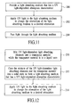
- a process flow diagram of a method for setting the attenuation of a light absorbing medium is provided in Fig. 3B.
- the process described with reference to Fig. 3B can be applied to the system of Fig. 3A.
- the intensity of the light that exits a light absorbing medium is measured.
- UV light can be continuously applied to the light absorbing medium or applied in a step-wise manner.
- Fig. 4A depicts another embodiment of a system 150 that can be used to change the attenuation of a light absorbing medium 100 from an initial attenuation to the desired attenuation.
- the system of Fig. 4A is similar to the system of Fig. 3A except that the system is configured to measure the intensity of the light before entering the light absorbing medium. Measuring the light intensity upon input and output allows the attenuation of the light absorbing medium to be quantified.
- light 114 from the light source 122 is directed towards the light absorbing medium.
- An input intensity measurement is obtained by the input light detector 146 and then provided to the controller 126.
- Light 112 that exits the light absorbing medium is measured by the output light detector 124 and the output intensity measurement is provided to the controller.
- the controller uses both the input and output light intensity measurements to determine the attenuation of the light absorbing medium.
- the application of UV light 110 to the light absorbing medium is then adjusted by the controller in response to the determined attenuation.
- the application of UV light is continued until the attenuation of the light absorbing medium reaches the desired attenuation.
- UV light can be applied to the light absorbing medium continuously or in a step-wise manner until the light absorbing medium reaches the desired attenuation.
- a process flow diagram of a method for setting the attenuation of a light absorbing medium is provided in Fig. 4B.
- the process described with reference to Fig. 4B can be applied to the system of Fig. 4A.
- the attenuation of the light absorbing medium is determined. For example, the attenuation is determined by obtaining input and output light intensity measurements.
- decision point 162 it is determined if the attenuation is at the desired attenuation. If the attenuation is at the desired attenuation, then the process is ended and no more UV light is applied to the light absorbing medium. If the attenuation is not at the desired attenuation, then at block 164 UV light is applied to the light absorbing medium and the process returns to block 160.
- UV light can be continuously applied to the light absorbing medium or applied in a step-wise manner.
- the attenuation of a light absorbing medium with a UV light-dependent absorption characteristic is changed from an initial attenuation to a desired attenuation by applying a pre-determined amount of UV light to the light absorbing medium.
- a pre-determined amount of UV light By applying a pre-determined amount of UV light, the attenuation of the light absorbing medium can be changed to the desired attenuation without using intensity measurements.
- the amount of UV light necessary to achieve the desired attenuation can be pre-determined based on, for example, previous results, testing, or calculations.
- a light absorbing medium with a UV light-dependent absorption characteristic as described above can have many applications. Some exemplary applications are described with reference to Figs. 5 - 10.
- Fig. 5 depicts an example of a light absorbing medium 100 with a UV light-dependent light absorption characteristic that is used in conjunction with a laser 170.
- the light absorbing medium is placed in an optical path of the laser's output beam 172 to attenuate the laser's output beam.
- UV light is applied to the light absorbing medium to change the attenuation of the light absorbing medium to a desired attenuation. UV light can be applied to the light absorbing medium before it is assembled with the laser or while it is in use with the laser.
- Fig. 6 depicts an example of a light absorbing medium 100 with a UV light-dependent absorption characteristic that is used in conjunction with an LED 174.
- the light absorbing medium is formed as a lens directly over the LED.
- a light absorbing medium formed as a lens simultaneously performs the functions of focusing and attenuating the output light.
- Fig. 7 depicts an alternative embodiment of the light absorbing medium of Fig. 6 in which the light absorbing medium is formed as a layer over an LED lens 176.
- the attenuation of the light absorbing medium is adjusted to the desired attenuation by the application of UV light.
- the attenuation of the light absorbing medium can be adjusted while the LED is generating light.
- Attenuation adjustments can be made to set the brightness of the LED.
- the attenuation of the light absorbing medium can be adjusted on a per-LED basis to account for differences in LED efficiency within a batch of LEDs or on a per-batch basis to account for differences in LED efficiency from batch to batch.
- Fig. 8 depicts an example of a light absorbing medium 100 with a UV light-dependent absorption characteristic that is used in conjunction with an LCD panel 178.
- the light absorbing medium is formed as a layer over a major surface of the LCD panel.
- the attenuation of the light absorbing medium is adjusted to the desired attenuation by the application of UV light.
- the attenuation of the light absorbing medium is adjusted across the LCD panel to balance the light that is emitted by the LCD panel.
- Fig. 9 depicts an example of a light absorbing medium with a UV light-dependent absorption characteristic that is used in conjunction with three individual color sensors 180A, 180B, 180C of a CCD sensor 182 (e.g., for use in a digital camera and commonly referred to as a "Three chip color camera").
- a light absorbing medium 100A, 100B, 100C is formed over each color-specific sensor.
- the attenuation of each light absorbing medium is individually adjusted to the desired attenuation by the application of UV light.
- the attenuation of each light absorbing medium is adjusted on a per-color basis to achieve fine color tuning for accurate color detection of incident light 184.
- Fig. 10 depicts an example of a light absorbing medium 100 with a UV light-dependent absorption characteristic that is formed on the surface of an optical element 186 such as a lens.
- the attenuation of the light absorbing medium is adjusted to the desired attenuation by the application of UV light.
- the lens is a camera lens and the attenuation is adjusted to set the filtering level of infra-red light.
- the light 114, 184 that is intended to be attenuated by the light absorbing medium should fall outside the UV band.
- the absorption of light can be used to change the color of the output light.
- a light absorbing medium that outputs colored light e.g., dark blue
- UV light can be changed by the application of UV light to output a different shade of the color (e.g., light blue).
- Fig. 11 is a process flow diagram of a method for attenuating light.
- a light absorbing medium that has a UV light-dependent absorption characteristic is provided.
- UV light is applied to the light absorbing medium to change the attenuation of the light absorbing medium to a desired attenuation.
- light is passed through the light absorbing medium.
- Fig. 12 is a process flow diagram of a method for producing a light absorbing medium having a desired attenuation.
- UV light-dependent light absorbing elements are mixed into a transparent material while the transparent material is in a liquid state.
- the mixture of the UV light-dependent light absorbing elements and the transparent material is cured into a solid state to form a light absorbing medium that has a UV light-dependent absorption characteristic.
- UV light is applied to the light absorbing medium to change the attenuation of the light absorbing medium to a desired attenuation.
Landscapes
- Physics & Mathematics (AREA)
- General Physics & Mathematics (AREA)
- Optics & Photonics (AREA)
- Spectroscopy & Molecular Physics (AREA)
- Nonlinear Science (AREA)
- Optical Modulation, Optical Deflection, Nonlinear Optics, Optical Demodulation, Optical Logic Elements (AREA)
Abstract
Description
- One way to reduce the intensity of a light beam is to pass the light beam through a light absorbing medium. The intensity of the exiting light beam can be controlled by selecting a light absorbing medium with the desired attenuation. Light absorbing mediums having fixed attenuation are well known in the optics field.
- While using a light absorbing medium with a fixed attenuation is an effective way to control the intensity of a light beam in a static and/or predictable environment, optical systems such as lasers, light emitting diodes (LEDs), liquid crystal displays (LCDs), and charged coupled devices (CCDs) often have dynamic and/or unpredictable optical characteristics. The dynamic and/or unpredictable nature of many optical systems can make it difficult to effectively control the optical systems using light absorbing mediums with fixed attenuation properties. For example, as the output characteristic of an LED or LCD panel degrades, an installed light absorbing medium with a fixed attenuation may no longer provide the ideal attenuation for the system. Additionally, because LEDs from the same batch do not always have the same optical output, light absorbing mediums with different attenuation properties may need to be matched with LEDs on a per-LED basis to produce a batch of LED based products with the same optical characteristics.
- In view of this, what is needed an optical element with an attenuation that can efficiently be adjusted to meet the needs of a specific application.
- An optical element includes a light absorbing medium formed of a transparent material and light absorbing elements encapsulated within the transparent material. The light absorbing elements have an ultraviolet (UV) light-dependent absorption characteristic and UV light is applied to the light absorbing medium to change the attenuation of the light absorbing medium to a desired attenuation. In an embodiment, the application of UV light to the light absorbing medium causes the light absorbing elements encapsulated within the light absorbing medium to degrade such that the amount of light absorbed by the light absorbing medium is reduced. Reducing the amount of light that is absorbed effectively reduces the attenuation of the light absorbing medium.
- In an embodiment, UV light is applied to the light absorbing medium in a controlled manner to change the attenuation of the light absorbing medium from an initial attenuation to the desired attenuation. A system for changing the attenuation of a light absorbing medium from an initial attenuation to the desired attenuation includes a light source, a light detector, a controller, and a UV light source.
- Other aspects and advantages of the present invention will become apparent from the following detailed description, taken in conjunction with the accompanying drawings, illustrated by way of example of the principles of the invention.
- Fig. 1 depicts a light absorbing medium that has a UV light-dependent absorption characteristic.
- Fig. 2 depicts the application of UV light to the light absorbing medium of Fig. 1 to change the attenuation of the light absorbing medium to a desired attenuation.
- Fig. 3A depicts an embodiment of a system that can be used to change the attenuation of a light absorbing medium from an initial attenuation to a desired attenuation.
- Fig. 3B depicts a process flow diagram of a method for setting the attenuation of a light absorbing medium.
- Fig. 4A depicts another embodiment of a system that can be used to change the attenuation of a light absorbing medium from an initial attenuation to a desired attenuation.
- Fig. 4B depicts a process flow diagram of a method for setting the attenuation of a light absorbing medium.
- Fig. 5 depicts a light absorbing medium with a UV light-dependent light absorption characteristic that is used in conjunction with a laser.
- Fig. 6 depicts a light absorbing medium with a UV light-dependent absorption characteristic that is used in conjunction with an LED.
- Fig. 7 depicts a light absorbing medium with a UV light-dependent absorption characteristic that is used in conjunction with an LED.
- Fig. 8 depicts a light absorbing medium with a UV light-dependent absorption characteristic that is used in conjunction with an LCD panel.
- Fig. 9 depicts a light absorbing medium with a UV light-dependent absorption characteristic that is used in conjunction with a color-specific set of sensors of a CCD sensor array.
- Fig. 10 depicts a light absorbing medium with a UV light-dependent absorption characteristic that is formed on the surface of an optical element such as a lens.
- Fig. 11 is a process flow diagram of a method for attenuating light in accordance with an embodiment of the invention.
- Fig. 12 is a process flow diagram of a method for producing a light absorbing medium having a desired attenuation in accordance with an embodiment of the invention.
- Throughout the description similar reference numbers may be used to identify similar elements.
- Fig. 1 depicts a
light absorbing medium 100 that has a UV light-dependent absorption characteristic. The light absorbing medium can be formed by mixinglight absorbing elements 102 into atransparent material 104 while the transparent material is in a liquid state. The mixture of the transparent material and the light absorbing elements is then cured into a solid state to form the light absorbing medium. The transparent material that is used to form the light absorbing medium can be any transparent material that can be mixed with light absorbing elements and then cured into a solid state. Example transparent materials include acrylics and epoxy. As used herein, the terms "transparent" and "transparent material" mean a material that is pervious to light or a material through which light can pass. "Transparent" and "transparent material" does not necessarily mean that light passes through the material such that objects or images can be seen as if there is no intervening material. That is, a material is considered transparent even if there is some diffusing of light within the material. As used herein, a transparent material includes a translucent material. - The
light absorbing elements 102 that are encapsulated within thetransparent material 104 have a characteristic that is sensitive to UV light. In an embodiment, the light absorbing elements have an optical absorption characteristic that is permanently altered as a result of exposure to UV light. Examples of light absorbing elements include ink and colored powder dye. When encapsulated into the transparent material, the sensitivity of the light absorbing elements to UV light causes thelight absorbing medium 100 to exhibit a UV light-dependent absorption characteristic. Changes in the absorption characteristic of the light absorbing medium are manifested as different attenuation levels when light is passed through the light absorbing medium. In an embodiment, the changes in the absorption characteristic of the light absorbing medium are permanent changes because the alterations caused by UV light exposure are not reversible. - In accordance with an embodiment of the invention, UV light is applied to the
light absorbing medium 100 depicted in Fig. 1 to change the attenuation of the light absorbing medium to a desired attenuation. Fig. 2 depicts the application ofUV light 110 to the light absorbing medium to change the attenuation of the light absorbing medium to the desired attenuation. In an embodiment, the application of UV light to the light absorbing medium causes thelight absorbing elements 102 encapsulated within thetransparent material 104 to degrade such that the amount of light absorbed by the light absorbing medium is reduced. Reducing the amount of light that is absorbed effectively reduces the attenuation of the light absorbing medium. For example, referring to Figs. 1 and 2, the intensity oflight output 112 from the light absorbing medium will be greater after the application of UV light. - In an embodiment, UV light is applied to the light absorbing medium in a controlled manner to change the attenuation of the light absorbing medium from an initial attenuation to the desired attenuation. Fig. 3A depicts an embodiment of a
system 120 that can be used to change the attenuation of alight absorbing medium 100 from an initial attenuation to the desired attenuation. The system includes alight source 122, alight detector 124, acontroller 126, and aUV light source 128. In operation,light 114 from the light source is directed into the light absorbing medium andlight 112 that exits the light absorbing medium is measured by the light detector. The intensity measurement is provided to the controller. The controller compares the measured light intensity to a desired light intensity and the output of the UV light source is controlled in response to the comparison. In an embodiment,UV light 110 is applied to the light absorbing medium until the intensity of the output light has increased to the desired intensity. Once the intensity of the output light reaches the desired intensity, the application of UV light is stopped. In an embodiment, the attenuation of the light absorbing medium can be adjusted in a step-wise manner by applying UV light in distinct intervals and measuring the intensity of the output light after each distinct interval. Alternatively, UV light is continuously applied to the light absorbing medium until the measured light intensity matches the desired light intensity. - A process flow diagram of a method for setting the attenuation of a light absorbing medium is provided in Fig. 3B. The process described with reference to Fig. 3B can be applied to the system of Fig. 3A. At
block 140, the intensity of the light that exits a light absorbing medium is measured. Atdecision point 142, it is determined if the measured light intensity is at the desired intensity. If the measured intensity is at the desired intensity, then atblock 144 the process is ended and no more UV light is applied to the light absorbing medium. If the measured intensity is not at the desired intensity, then more UV light is applied to the light absorbing medium and the process returns to block 140. UV light can be continuously applied to the light absorbing medium or applied in a step-wise manner. - Fig. 4A depicts another embodiment of a
system 150 that can be used to change the attenuation of a light absorbing medium 100 from an initial attenuation to the desired attenuation. The system of Fig. 4A is similar to the system of Fig. 3A except that the system is configured to measure the intensity of the light before entering the light absorbing medium. Measuring the light intensity upon input and output allows the attenuation of the light absorbing medium to be quantified. In operation, light 114 from thelight source 122 is directed towards the light absorbing medium. An input intensity measurement is obtained by theinput light detector 146 and then provided to thecontroller 126.Light 112 that exits the light absorbing medium is measured by theoutput light detector 124 and the output intensity measurement is provided to the controller. The controller uses both the input and output light intensity measurements to determine the attenuation of the light absorbing medium. The application ofUV light 110 to the light absorbing medium is then adjusted by the controller in response to the determined attenuation. In an embodiment, the application of UV light is continued until the attenuation of the light absorbing medium reaches the desired attenuation. UV light can be applied to the light absorbing medium continuously or in a step-wise manner until the light absorbing medium reaches the desired attenuation. - A process flow diagram of a method for setting the attenuation of a light absorbing medium is provided in Fig. 4B. The process described with reference to Fig. 4B can be applied to the system of Fig. 4A. At
block 160, the attenuation of the light absorbing medium is determined. For example, the attenuation is determined by obtaining input and output light intensity measurements. Atdecision point 162, it is determined if the attenuation is at the desired attenuation. If the attenuation is at the desired attenuation, then the process is ended and no more UV light is applied to the light absorbing medium. If the attenuation is not at the desired attenuation, then atblock 164 UV light is applied to the light absorbing medium and the process returns to block 160. UV light can be continuously applied to the light absorbing medium or applied in a step-wise manner. - Although two systems for changing the attenuation of a UV light-dependent light absorbing medium are described, other systems are possible.
- In an alternative embodiment, the attenuation of a light absorbing medium with a UV light-dependent absorption characteristic is changed from an initial attenuation to a desired attenuation by applying a pre-determined amount of UV light to the light absorbing medium. By applying a pre-determined amount of UV light, the attenuation of the light absorbing medium can be changed to the desired attenuation without using intensity measurements. The amount of UV light necessary to achieve the desired attenuation can be pre-determined based on, for example, previous results, testing, or calculations.
- A light absorbing medium with a UV light-dependent absorption characteristic as described above can have many applications. Some exemplary applications are described with reference to Figs. 5 - 10. Fig. 5 depicts an example of a light absorbing medium 100 with a UV light-dependent light absorption characteristic that is used in conjunction with a
laser 170. In this application, the light absorbing medium is placed in an optical path of the laser'soutput beam 172 to attenuate the laser's output beam. As described above, UV light is applied to the light absorbing medium to change the attenuation of the light absorbing medium to a desired attenuation. UV light can be applied to the light absorbing medium before it is assembled with the laser or while it is in use with the laser. - Fig. 6 depicts an example of a light absorbing medium 100 with a UV light-dependent absorption characteristic that is used in conjunction with an
LED 174. In this application, the light absorbing medium is formed as a lens directly over the LED. A light absorbing medium formed as a lens simultaneously performs the functions of focusing and attenuating the output light. Fig. 7 depicts an alternative embodiment of the light absorbing medium of Fig. 6 in which the light absorbing medium is formed as a layer over anLED lens 176. In either embodiment, the attenuation of the light absorbing medium is adjusted to the desired attenuation by the application of UV light. The attenuation of the light absorbing medium can be adjusted while the LED is generating light. Attenuation adjustments can be made to set the brightness of the LED. For example, the attenuation of the light absorbing medium can be adjusted on a per-LED basis to account for differences in LED efficiency within a batch of LEDs or on a per-batch basis to account for differences in LED efficiency from batch to batch. - Fig. 8 depicts an example of a light absorbing medium 100 with a UV light-dependent absorption characteristic that is used in conjunction with an
LCD panel 178. In this application, the light absorbing medium is formed as a layer over a major surface of the LCD panel. The attenuation of the light absorbing medium is adjusted to the desired attenuation by the application of UV light. In an embodiment, the attenuation of the light absorbing medium is adjusted across the LCD panel to balance the light that is emitted by the LCD panel. - Fig. 9 depicts an example of a light absorbing medium with a UV light-dependent absorption characteristic that is used in conjunction with three
individual color sensors light absorbing medium incident light 184. - Fig. 10 depicts an example of a light absorbing medium 100 with a UV light-dependent absorption characteristic that is formed on the surface of an
optical element 186 such as a lens. The attenuation of the light absorbing medium is adjusted to the desired attenuation by the application of UV light. In an embodiment, the lens is a camera lens and the attenuation is adjusted to set the filtering level of infra-red light. - Because of the UV dependency of the
light absorbing medium 100, in most applications the light 114, 184 that is intended to be attenuated by the light absorbing medium should fall outside the UV band. - In an embodiment, the absorption of light can be used to change the color of the output light. For example, a light absorbing medium that outputs colored light (e.g., dark blue) can be changed by the application of UV light to output a different shade of the color (e.g., light blue).
- Fig. 11 is a process flow diagram of a method for attenuating light. At
block 200, a light absorbing medium that has a UV light-dependent absorption characteristic is provided. Atblock 202, UV light is applied to the light absorbing medium to change the attenuation of the light absorbing medium to a desired attenuation. Atblock 204, light is passed through the light absorbing medium. - Fig. 12 is a process flow diagram of a method for producing a light absorbing medium having a desired attenuation. At
block 210, UV light-dependent light absorbing elements are mixed into a transparent material while the transparent material is in a liquid state. Atblock 212, the mixture of the UV light-dependent light absorbing elements and the transparent material is cured into a solid state to form a light absorbing medium that has a UV light-dependent absorption characteristic. Atblock 214, UV light is applied to the light absorbing medium to change the attenuation of the light absorbing medium to a desired attenuation. - Although specific embodiments of the invention have been described and illustrated, the invention is not to be limited to the specific forms or arrangements of parts so described and illustrated. The scope of the invention is to be defined by the claims appended hereto and their equivalents.
Claims (10)
- An optical element comprising:a light absorbing medium (100) comprising;
a transparent material (104); and
light absorbing elements (102) encapsulated within the transparent material, wherein the light absorbing elements have an ultraviolet (UV) light-dependent absorption characteristic. - The optical element of claim 1 further comprising a system (120) for changing the attenuation of the light absorbing medium (100) from an initial attenuation to a desired attenuation.
- The optical element of claim 2 further comprising a UV light source (128) and a controller (126) configured to control the application of UV light to the light absorbing medium.
- The optical element of claim 3 further comprising a light detector (124) configured to detect light exiting the light absorbing medium.
- The optical element of claim 1 wherein the transparent material (104) is epoxy.
- The optical element of claim 1 wherein the light absorbing elements (102) include one of ink and colored powder dye.
- A method for attenuating light comprising:providing (200) a light absorbing medium (100) that has a UV light-dependent absorption characteristic;applying (202) UV light to the light absorbing medium to change the attenuation of the light absorbing medium to a desired attenuation; andpassing (204) light through the light absorbing medium.
- The method of claim 7 further including:measuring the intensity of the light that exits the light absorbing medium (100);comparing the measured intensity to a desired intensity; andadjusting the application of the UV light (110) to the light absorbing medium in response to the comparison.
- The method of claim 8 further including ending the application of the UV light (110) when the measured intensity matches the desired intensity.
- The method of claim 7 wherein applying UV light (110) to the light absorbing medium (100) comprises applying a pre-determined amount of UV light to the light absorbing medium.
Applications Claiming Priority (1)
| Application Number | Priority Date | Filing Date | Title |
|---|---|---|---|
| US11/186,110 US7345813B2 (en) | 2005-07-21 | 2005-07-21 | UV adjustable optical attenuator |
Publications (1)
| Publication Number | Publication Date |
|---|---|
| EP1746396A1 true EP1746396A1 (en) | 2007-01-24 |
Family
ID=36952595
Family Applications (1)
| Application Number | Title | Priority Date | Filing Date |
|---|---|---|---|
| EP06014356A Ceased EP1746396A1 (en) | 2005-07-21 | 2006-07-11 | UV adjustable optical attenuator |
Country Status (2)
| Country | Link |
|---|---|
| US (1) | US7345813B2 (en) |
| EP (1) | EP1746396A1 (en) |
Families Citing this family (3)
| Publication number | Priority date | Publication date | Assignee | Title |
|---|---|---|---|---|
| US20130315527A1 (en) * | 2012-05-25 | 2013-11-28 | Xiaochen Sun | Photocarrier-injecting variable optical attenuator |
| ES2478693B1 (en) * | 2012-12-21 | 2015-04-29 | Universidad Complutense De Madrid | Short wavelength blocking element in led type lighting sources |
| US11435277B2 (en) * | 2015-10-20 | 2022-09-06 | Tintometer, Gmbh | Device for removing energy from a beam and a method(s) of use thereof |
Citations (2)
| Publication number | Priority date | Publication date | Assignee | Title |
|---|---|---|---|---|
| JPS5990805A (en) * | 1982-11-16 | 1984-05-25 | Nippon Sheet Glass Co Ltd | Variable attenuator of optical fiber |
| US6066844A (en) * | 1998-03-07 | 2000-05-23 | Lucent Technologies Inc. | Optical receiver with integrated variable attenuator |
Family Cites Families (7)
| Publication number | Priority date | Publication date | Assignee | Title |
|---|---|---|---|---|
| US4890075A (en) * | 1986-07-31 | 1989-12-26 | The United States Of America As Represented By The Secretary Of The Army | Optical radiation limiter |
| US5847507A (en) * | 1997-07-14 | 1998-12-08 | Hewlett-Packard Company | Fluorescent dye added to epoxy of light emitting diode lens |
| US6167185A (en) | 1998-11-24 | 2000-12-26 | Jds Fitel Inc. | Adjustable optical attenuator |
| US6021520A (en) * | 1999-04-21 | 2000-02-08 | Wang-Lee; Min-Young | Eyeshield for a welder's mask |
| JP2002174720A (en) * | 2000-12-06 | 2002-06-21 | Mitsubishi Electric Corp | Ultraviolet absorbing device and optical device using the same |
| US6580868B2 (en) | 2001-03-19 | 2003-06-17 | Optiwork, Inc. | High-resolution variable optical attenuator with mechanical adjustment |
| US7005679B2 (en) * | 2003-05-01 | 2006-02-28 | Cree, Inc. | Multiple component solid state white light |
-
2005
- 2005-07-21 US US11/186,110 patent/US7345813B2/en not_active Expired - Fee Related
-
2006
- 2006-07-11 EP EP06014356A patent/EP1746396A1/en not_active Ceased
Patent Citations (2)
| Publication number | Priority date | Publication date | Assignee | Title |
|---|---|---|---|---|
| JPS5990805A (en) * | 1982-11-16 | 1984-05-25 | Nippon Sheet Glass Co Ltd | Variable attenuator of optical fiber |
| US6066844A (en) * | 1998-03-07 | 2000-05-23 | Lucent Technologies Inc. | Optical receiver with integrated variable attenuator |
Non-Patent Citations (2)
| Title |
|---|
| PATENT ABSTRACTS OF JAPAN vol. 008, no. 208 (P - 302) 21 September 1984 (1984-09-21) * |
| ZHOU, MING: "Low-loss polymeric materials for passive waveguide components in fiber optical telecommunication.", OPTICAL ENGINEERING, vol. 41, no. 7, July 2002 (2002-07-01), pages 1631 - 1643, XP002399066 * |
Also Published As
| Publication number | Publication date |
|---|---|
| US20070019287A1 (en) | 2007-01-25 |
| US7345813B2 (en) | 2008-03-18 |
Similar Documents
| Publication | Publication Date | Title |
|---|---|---|
| US20230103572A1 (en) | Limitation of Noise on Light Detectors using an Aperture | |
| KR102848333B1 (en) | A photometric device including an internal spectral reference unit | |
| US7929220B2 (en) | Adjustable apodized lens aperture | |
| KR20090040343A (en) | Method and apparatus for determining light intensity and peak wavelength | |
| JP2005070025A (en) | Light source testing system and method | |
| US7345813B2 (en) | UV adjustable optical attenuator | |
| US20070153278A1 (en) | System and method for color measurements or other spectral measurements of a material | |
| Vikova et al. | A unique device for measurement of photochromic textiles | |
| KR101303376B1 (en) | Illumination system, light-sensing plate and display device | |
| EP3551986B1 (en) | Led light source probe card technology for testing cmos image scan devices | |
| KR102788708B1 (en) | Dual photodiode radiometer | |
| US6734957B2 (en) | Visible light sensor mechanism for constant brightness projection systems | |
| US20190331526A1 (en) | A Photometric Test System for Light Emitting Devices | |
| US20200150249A1 (en) | Lidar sensor with attenuating element | |
| KR20030048023A (en) | Sensor unit for automatically switching lighting devices and a coupling medium for a sensor unit | |
| JPH03262931A (en) | Light source unit for calibrating sensitivity of photomultiplier tube | |
| TWI408345B (en) | Adjustable standard low luminance device | |
| RU2470262C1 (en) | Method and apparatus for simulating backlight without background radiation spectrum distortion | |
| US20210364424A1 (en) | Sensor having enhanced detection capability | |
| US20090200456A1 (en) | Angle selective photo sensor structures for accurate color control, out coupling and background rejection, in led luminaries | |
| JP3890324B2 (en) | Color toner density detector | |
| Wysokinski et al. | Development, properties and applications of a photochromic adaptive filter | |
| RU2349946C1 (en) | Feedback projection optical device | |
| JP3650777B1 (en) | Colorimeter | |
| Wysokinski | Application of the photochromic adaptive filter for all-optical image processing and its characterization |
Legal Events
| Date | Code | Title | Description |
|---|---|---|---|
| PUAI | Public reference made under article 153(3) epc to a published international application that has entered the european phase |
Free format text: ORIGINAL CODE: 0009012 |
|
| AK | Designated contracting states |
Kind code of ref document: A1 Designated state(s): AT BE BG CH CY CZ DE DK EE ES FI FR GB GR HU IE IS IT LI LT LU LV MC NL PL PT RO SE SI SK TR |
|
| AX | Request for extension of the european patent |
Extension state: AL BA HR MK YU |
|
| 17P | Request for examination filed |
Effective date: 20070216 |
|
| AKX | Designation fees paid |
Designated state(s): DE GB |
|
| 17Q | First examination report despatched |
Effective date: 20071214 |
|
| RBV | Designated contracting states (corrected) |
Designated state(s): GB |
|
| REG | Reference to a national code |
Ref country code: DE Ref legal event code: 8566 |
|
| STAA | Information on the status of an ep patent application or granted ep patent |
Free format text: STATUS: THE APPLICATION HAS BEEN REFUSED |
|
| 18R | Application refused |
Effective date: 20111007 |