EP1746352A2 - Heizungsanlage - Google Patents
Heizungsanlage Download PDFInfo
- Publication number
- EP1746352A2 EP1746352A2 EP06253789A EP06253789A EP1746352A2 EP 1746352 A2 EP1746352 A2 EP 1746352A2 EP 06253789 A EP06253789 A EP 06253789A EP 06253789 A EP06253789 A EP 06253789A EP 1746352 A2 EP1746352 A2 EP 1746352A2
- Authority
- EP
- European Patent Office
- Prior art keywords
- heating
- water
- heat
- storage tank
- heating system
- Prior art date
- Legal status (The legal status is an assumption and is not a legal conclusion. Google has not performed a legal analysis and makes no representation as to the accuracy of the status listed.)
- Granted
Links
Images


Classifications
-
- F—MECHANICAL ENGINEERING; LIGHTING; HEATING; WEAPONS; BLASTING
- F24—HEATING; RANGES; VENTILATING
- F24H—FLUID HEATERS, e.g. WATER OR AIR HEATERS, HAVING HEAT-GENERATING MEANS, e.g. HEAT PUMPS, IN GENERAL
- F24H9/00—Details
- F24H9/20—Arrangement or mounting of control or safety devices
- F24H9/2007—Arrangement or mounting of control or safety devices for water heaters
- F24H9/2014—Arrangement or mounting of control or safety devices for water heaters using electrical energy supply
- F24H9/2021—Storage heaters
-
- F—MECHANICAL ENGINEERING; LIGHTING; HEATING; WEAPONS; BLASTING
- F24—HEATING; RANGES; VENTILATING
- F24D—DOMESTIC- OR SPACE-HEATING SYSTEMS, e.g. CENTRAL HEATING SYSTEMS; DOMESTIC HOT-WATER SUPPLY SYSTEMS; ELEMENTS OR COMPONENTS THEREFOR
- F24D11/00—Central heating systems using heat accumulated in storage masses
- F24D11/002—Central heating systems using heat accumulated in storage masses water heating system
-
- F—MECHANICAL ENGINEERING; LIGHTING; HEATING; WEAPONS; BLASTING
- F24—HEATING; RANGES; VENTILATING
- F24D—DOMESTIC- OR SPACE-HEATING SYSTEMS, e.g. CENTRAL HEATING SYSTEMS; DOMESTIC HOT-WATER SUPPLY SYSTEMS; ELEMENTS OR COMPONENTS THEREFOR
- F24D3/00—Hot-water central heating systems
- F24D3/08—Hot-water central heating systems in combination with systems for domestic hot-water supply
-
- F—MECHANICAL ENGINEERING; LIGHTING; HEATING; WEAPONS; BLASTING
- F24—HEATING; RANGES; VENTILATING
- F24H—FLUID HEATERS, e.g. WATER OR AIR HEATERS, HAVING HEAT-GENERATING MEANS, e.g. HEAT PUMPS, IN GENERAL
- F24H9/00—Details
- F24H9/18—Arrangement or mounting of grates or heating means
- F24H9/1809—Arrangement or mounting of grates or heating means for water heaters
- F24H9/1818—Arrangement or mounting of electric heating means
-
- F—MECHANICAL ENGINEERING; LIGHTING; HEATING; WEAPONS; BLASTING
- F24—HEATING; RANGES; VENTILATING
- F24D—DOMESTIC- OR SPACE-HEATING SYSTEMS, e.g. CENTRAL HEATING SYSTEMS; DOMESTIC HOT-WATER SUPPLY SYSTEMS; ELEMENTS OR COMPONENTS THEREFOR
- F24D2200/00—Heat sources or energy sources
- F24D2200/08—Electric heater
-
- F—MECHANICAL ENGINEERING; LIGHTING; HEATING; WEAPONS; BLASTING
- F24—HEATING; RANGES; VENTILATING
- F24D—DOMESTIC- OR SPACE-HEATING SYSTEMS, e.g. CENTRAL HEATING SYSTEMS; DOMESTIC HOT-WATER SUPPLY SYSTEMS; ELEMENTS OR COMPONENTS THEREFOR
- F24D2200/00—Heat sources or energy sources
- F24D2200/14—Solar energy
-
- F—MECHANICAL ENGINEERING; LIGHTING; HEATING; WEAPONS; BLASTING
- F24—HEATING; RANGES; VENTILATING
- F24D—DOMESTIC- OR SPACE-HEATING SYSTEMS, e.g. CENTRAL HEATING SYSTEMS; DOMESTIC HOT-WATER SUPPLY SYSTEMS; ELEMENTS OR COMPONENTS THEREFOR
- F24D2200/00—Heat sources or energy sources
- F24D2200/16—Waste heat
-
- Y—GENERAL TAGGING OF NEW TECHNOLOGICAL DEVELOPMENTS; GENERAL TAGGING OF CROSS-SECTIONAL TECHNOLOGIES SPANNING OVER SEVERAL SECTIONS OF THE IPC; TECHNICAL SUBJECTS COVERED BY FORMER USPC CROSS-REFERENCE ART COLLECTIONS [XRACs] AND DIGESTS
- Y02—TECHNOLOGIES OR APPLICATIONS FOR MITIGATION OR ADAPTATION AGAINST CLIMATE CHANGE
- Y02B—CLIMATE CHANGE MITIGATION TECHNOLOGIES RELATED TO BUILDINGS, e.g. HOUSING, HOUSE APPLIANCES OR RELATED END-USER APPLICATIONS
- Y02B10/00—Integration of renewable energy sources in buildings
- Y02B10/20—Solar thermal
-
- Y—GENERAL TAGGING OF NEW TECHNOLOGICAL DEVELOPMENTS; GENERAL TAGGING OF CROSS-SECTIONAL TECHNOLOGIES SPANNING OVER SEVERAL SECTIONS OF THE IPC; TECHNICAL SUBJECTS COVERED BY FORMER USPC CROSS-REFERENCE ART COLLECTIONS [XRACs] AND DIGESTS
- Y02—TECHNOLOGIES OR APPLICATIONS FOR MITIGATION OR ADAPTATION AGAINST CLIMATE CHANGE
- Y02B—CLIMATE CHANGE MITIGATION TECHNOLOGIES RELATED TO BUILDINGS, e.g. HOUSING, HOUSE APPLIANCES OR RELATED END-USER APPLICATIONS
- Y02B10/00—Integration of renewable energy sources in buildings
- Y02B10/70—Hybrid systems, e.g. uninterruptible or back-up power supplies integrating renewable energies
Definitions
- the present invention relates to a heating system in which a hot water cylinder is used to provide hot water and heating.
- hot water from a boiler (typically gas or oil fired, but sometimes electrical) is pumped through a heat exchanger coil which itself is housed within the hot water cylinder. Heat exchange with cold water entering the cylinder from the bottom occurs and in this way the cold water is heated to be used to supply hot water taps, showers, washing machines etc.
- a separate supply of hot water from the same boiler is passed directly through the radiators for central heating of a building.
- a relatively low powered electrical immersion heater is often installed within the cylinder that can be controlled separately to the boiler.
- Immersion heaters are often used to augment hot water heating from the boiler; to provide a heating boost when hot water is needed and there is not the time to wait for the boiler to heat the water; or when it is not desired to use the boiler.
- a boiler is always required. Whilst there are a variety of options, environment driven regulations demand even more efficient boilers. In the UK it is now a requirement to fit a condensing boiler (typically 10-15% more efficient than a conventional type) where this is practical and reasonably economically viable.
- a condensing boiler recovers waste energy from flue gases and uses this to supplement heat from the burners.
- a condensing boiler also requires the installation of a condensate drain. Whilst the provision of this drain can be simple in some cases, in others, for example in existing dwellings where the boiler is to be sited remotely from a wastewater drain, it is less practical.
- the condensate produced from the combustion process contains acids.
- a conventional combined hot water and central heating system is relatively costly to install.
- a gas/oil and electric supply must be installed to the boiler, which for reasons of general practicality may be necessarily some way distance from the hot water cylinder.
- a flue to an external wall or roof may be required.
- Pipe-work of substantial diameter typically around 28mm
- a topping up system must be installed at a level higher than the highest radiator (typically in the loft space) and this requires additional labour expense.
- a heating system in a preferred embodiment of the present invention, includes a water storage tank, a heat exchanger and a plurality of electrical heating elements, the heat exchanger and electrical heating elements being mounted substantially within the water storage tank, the electrical heating elements being controllable to heat water within the water storage tank and the heat exchanger being arranged to be coupled to a central heating circuit for transferring heat from the water in the storage tank to heat the central heating circuit
- the electrical heating elements are arranged into a plurality of circuits, each circuit being independently powered and controllable.
- the heating system may further comprise a secondary heat source arranged to provide auxiliary heat to the water within the water storage tank.
- the secondary heat source may include at least one of:
- the heating system may further comprise a master controller arranged to communicate with the respective controllers of each circuit and to control operation of the heating elements in dependence on a predetermined heating program.
- the master controller may be arranged to detect failure of a circuit and to adjust operation of other operational circuits to compensate.
- the master controller may be arranged to supplement heating by the secondary heat source with heat from the heating elements in dependence on the predetermined heating program.
- a heat transfer medium may be pumped through the heat exchanger to obtain heat for the central heating circuit.
- the heating system may further comprise a pressurised water supply system arranged to supply water to the water storage tank substantially at a predetermined pressure.
- the present invention seeks to provide an improved system of central heating and hot water supply, which removes the need for a conventional boiler, gas supply and the ventilation required for fuel combustion.
- the system could be used in any environment but is particularly applicable to self-contained flats and other small dwellings, offices and granny annexes where access for gas supplies, ventilation and the like is not possible.
- An immersion heating system is installed, preferably in the lower portion of the tank and will be in direct contact with the water contained within the tank.
- a heat exchanger preferably a copper coil is positioned within the tank to communicate directly with a central heating circuit. Water within the tank and without the coil is heated under the action of the immersion heater and supplied to the dwellings hot water and central heating connections as required.
- Heating systems according to the present invention could be retrofitted to existing installations.
- Another heat transfer medium such as air, could be within the heat transfer coil and could feed central heating elements other than 'wet' radiators.
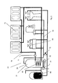
- Figure 1 is a schematic diagram of a heating system according to an embodiment of the present invention.
- the heating system 10 includes a hot water tank 20.
- An electrical heater 30 and a heat exchanger 40 are mounted within the hot water tank 20.
- the electrical heater comprises a plurality of independently powered and controllable heating elements and is discussed in greater detail with reference to Figure 3.
- the electrical heater 30 is controlled by a controller 35 to heat water 21 within the hot water tank 20.
- the hot water tank 20 includes a cold water supply inlet 22 for receiving cold water from a supply to replace water used and a hot water supply outlet 23 for providing hot water to hot water plumbing 50, appliances 60 and the like.
- the heat exchanger 40 is positioned within the hot water tank 20 in contact with the heated water 21 stored in the hot water tank 20.
- the heat exchanger 40 is coupled to a central heating circuit 70. Water within the central heating circuit 70 can be selectively pumped via one or more pumps 71 through the heat exchanger 40. Heat from the water 21 within the hot water tank 20 is transferred to water within the central heating circuit 70 as it passes through the heat exchanger 40 enabling radiators 73 and the like that are part of the central heating circuit to be heated. It will be appreciated that the heat exchanger may also be coupled to other heating elements such as under floor heating.
- Hot water is drawn from the cylinder 20 and mixed with cold water at a thermostatic valve 72 enabling safer lower temperatures at hot water outlets 60.
- the pump 73 is preferably controlled by a thermostat and programmable timer with override so that heat is available on demand subject to hot water being present in the tank 20.
- the heat exchanger 40 is a copper coil, although any other suitable material may be used.
- the hot water tank 20 is insulated enabling heated water to be stored in the tank for provision on demand via outlet 23.
- the hot water tank 20 is insulated to prevent heat loss and enable heated water to be stored for supply on demand.
- the hot water tank is an un-vented hot water cylinder such as existing pressurised systems. It will be appreciated that the present invention is also applicable for use with conventional vented systems.
- the hot water tank 20 could be copper, stainless steel, glass lined, or materials such as plastics.
- the electrical heater 30 is formed from 3 circuits of heating elements, each element having a rating resulting in a maximum power rating of between 3 and 9KW (the higher end being intended for providing heat to whole buildings, blocks of flats etc).
- a maximum power rating of between 3 and 9KW (the higher end being intended for providing heat to whole buildings, blocks of flats etc).
- other types of heater and power ratings could be substituted.
- the power rating of the heater 30 (which will typically be much more powerful than conventional electrical immersion heaters) is selected in dependence on the physical size of the heater element or elements (i.e fitting it through the hole or holes in the cylinder), and heat dissipation properties of the heater 30 (to reduce the possibility of overheating).
- the heating element is made from titanium (or a material of similar properties) as it is more capable of sustaining the heat transfer required than would be a standard material such as stainless steel.
- a larger wattage heater system could be installed (and might be advantageous in terms of cylinder size and speed of heating) subject the requisite supply and overload protection systems.
- heating elements having an increased surface area may be used.
- the elements may via include dimples or other surface features or fins attached to the outside of the elements.
- a ship in a bottle type arrangement may be used to erect the fins or extended surface area once inside the cylinder.
- a heating element may have two configurations, a first configuration having dimensions for installation via an appropriate aperture in the cylinder and a second configuration having an enlarged surface area. The element is installed in the first configuration and the shifted to the second configuration once in the cylinder.
- Figure 2 is a schematic diagram of a heating system according to an alternate embodiment of the present invention.
- the heating system 10 is used with a pressurised water supply system, an example of such a system is described in Patent No. GB2349908 , which is incorporated herein by reference.
- an accumulator having an internal diaphragm 80 is used. Incoming cold water is stored within the diaphragm 80 at mains pressure. The air space between the diaphragm and accumulator housing is pressurised to balance the supply and maintain pressure to the tank 20 and cold water outlets. When both hot and cold water outlets are turned on, stored water from the accumulator supplements incoming water from the main resulting in consistent water pressure for as long as there is water in the diaphragm 80.
- Figure 3 is a schematic diagram of an electrical heater suitable for use in a preferred embodiment of the present invention.
- the electrical heater 30 includes a number of electrical heating elements 31.
- the elements are arranged into circuits 32, each circuit having a separate power source 33 so that the heater 30 will continue to function should one or more circuits 32 fail.
- three circuits 32 are installed, although any number could be used depending on the desired implementation and application.
- Each circuit 32 could include one or more element(s) 31.
- each circuit may include a separate controller 35.
- Close control of the electrical heating elements 31 is achieved by one or more controllers 35, which may, for example, be programmed to provide scheduled heating and make use of facilities such as economy tariff energy.
- the one or more controller(s) 35 may be coupled to the pumps 71 and/or valves 72 to control the central heating circuit 70.
- the system includes a master controller (such as a 7 day programmer).
- the master controller is connected to a system controller that is arranged to control operation of the circuits.
- the system controller may be linked to a display for providing status information e.g. 'Call engineer'.
- the system controller preferably controls the circuits such that they are never turned on simultaneously to reduce starting load on the system. For example, the first is turned on, then after a preset temp rise (e.g. 3 °C) the second is turned on, then another 3 °C and the third is turned on. This could apply 'from cold' or when the system is ticking over. It's likely that only one element would be used in any case to keep the system ticking over, especially if no water has been drawn. It will be appreciated that other control arrangements could easily be implemented.
- a preset temp rise e.g. 3 °C
- the system controller alternates the order in which the elements are turned on. Monday it might be 1,2 3; Tuesday might be 3,1,2 etc. This prolongs the life of the elements by sharing the starting load, especially from cold.
- the system controller determines if the system is already operating at full capacity and If not already at full capacity, the system controller switches in a second or third circuit to compensate for that lost.
- Individual circuits or elements may be controlled (for example via a PID controller or the like). Alternatively, further control could be added via a controller with greater functionality (such as a PID controller) whereby the power supplied to individual elements could be controlled such that proportions of that element's possible output could be switched in as required. In this way, low level heating could be supplied demand applications or better temperature control achieved.
- a controller with greater functionality such as a PID controller
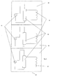
- Figure 4 is a schematic diagram of a heating system according to another embodiment of the present invention.
- a secondary heat source 90 is used. Heat is sourced from a Photovoltaic panel or solar heat exchanger 95 to supplement the heat energy supplied by the immersion heater 30.
- the secondary heat source 90 may be relied upon as the primary source for heating the hot water tank 20 and augmented by the heater 30 as is needed.
- secondary heat sources could also be included. Indeed, multiple secondary heat sources of the same or different types could be used.
Landscapes
- Engineering & Computer Science (AREA)
- Physics & Mathematics (AREA)
- Thermal Sciences (AREA)
- Chemical & Material Sciences (AREA)
- Combustion & Propulsion (AREA)
- Mechanical Engineering (AREA)
- General Engineering & Computer Science (AREA)
- Water Supply & Treatment (AREA)
- Heat-Pump Type And Storage Water Heaters (AREA)
- Central Heating Systems (AREA)
- Sorption Type Refrigeration Machines (AREA)
- General Induction Heating (AREA)
Applications Claiming Priority (1)
| Application Number | Priority Date | Filing Date | Title |
|---|---|---|---|
| GBGB0514800.2A GB0514800D0 (en) | 2005-07-19 | 2005-07-19 | Heating system |
Publications (3)
| Publication Number | Publication Date |
|---|---|
| EP1746352A2 true EP1746352A2 (de) | 2007-01-24 |
| EP1746352A3 EP1746352A3 (de) | 2008-12-17 |
| EP1746352B1 EP1746352B1 (de) | 2011-03-30 |
Family
ID=34897466
Family Applications (1)
| Application Number | Title | Priority Date | Filing Date |
|---|---|---|---|
| EP06253789A Active EP1746352B1 (de) | 2005-07-19 | 2006-07-19 | Heizungsanlage |
Country Status (4)
| Country | Link |
|---|---|
| EP (1) | EP1746352B1 (de) |
| AT (1) | ATE503971T1 (de) |
| DE (1) | DE602006020958D1 (de) |
| GB (1) | GB0514800D0 (de) |
Cited By (6)
| Publication number | Priority date | Publication date | Assignee | Title |
|---|---|---|---|---|
| RU2364802C1 (ru) * | 2007-12-26 | 2009-08-20 | Открытое акционерное общество Проектный, научно-исследовательский и конструкторский институт "Красноярский ПромстройНИИпроект" | Электрокотельная теплоаккумуляционная |
| CN102777959A (zh) * | 2012-08-24 | 2012-11-14 | 江苏联宏自动化系统工程有限公司 | 一种基于混水装置的供热调节和控制方法 |
| ES2415060A1 (es) * | 2012-01-20 | 2013-07-23 | David BECERRA LÓPEZ | Sistema térmico electro-solar |
| CN106152494A (zh) * | 2015-04-24 | 2016-11-23 | 王锦林 | 连带生活用水自动控制节能型无压热水器 |
| GR20180100343A (el) * | 2018-07-25 | 2020-03-18 | Μακαριος Θεοδωρου Τσοπουλιδης | Νεου τυπου θερμοσιφωνας με δοχειο αδρανειας |
| GB2643734A (en) * | 2024-08-29 | 2026-03-04 | Bur Bax 10 Ltd | Heating system |
Families Citing this family (1)
| Publication number | Priority date | Publication date | Assignee | Title |
|---|---|---|---|---|
| KR102144808B1 (ko) * | 2017-07-24 | 2020-08-14 | 주식회사 경동나비엔 | 난방 및 온수 겸용 보일러 시스템 |
Citations (1)
| Publication number | Priority date | Publication date | Assignee | Title |
|---|---|---|---|---|
| GB2349908A (en) | 1999-03-16 | 2000-11-15 | Stephen John Elsey | Water supply arrangement |
Family Cites Families (2)
| Publication number | Priority date | Publication date | Assignee | Title |
|---|---|---|---|---|
| US4588875A (en) * | 1982-09-30 | 1986-05-13 | A. O. Smith Corporation | Multiple load control apparatus with load equalization |
| GB2181218A (en) * | 1985-10-01 | 1987-04-15 | Peter Loi | Central heating apparatus |
-
2005
- 2005-07-19 GB GBGB0514800.2A patent/GB0514800D0/en not_active Ceased
-
2006
- 2006-07-19 AT AT06253789T patent/ATE503971T1/de not_active IP Right Cessation
- 2006-07-19 EP EP06253789A patent/EP1746352B1/de active Active
- 2006-07-19 DE DE602006020958T patent/DE602006020958D1/de active Active
Patent Citations (1)
| Publication number | Priority date | Publication date | Assignee | Title |
|---|---|---|---|---|
| GB2349908A (en) | 1999-03-16 | 2000-11-15 | Stephen John Elsey | Water supply arrangement |
Cited By (8)
| Publication number | Priority date | Publication date | Assignee | Title |
|---|---|---|---|---|
| RU2364802C1 (ru) * | 2007-12-26 | 2009-08-20 | Открытое акционерное общество Проектный, научно-исследовательский и конструкторский институт "Красноярский ПромстройНИИпроект" | Электрокотельная теплоаккумуляционная |
| ES2415060A1 (es) * | 2012-01-20 | 2013-07-23 | David BECERRA LÓPEZ | Sistema térmico electro-solar |
| CN102777959A (zh) * | 2012-08-24 | 2012-11-14 | 江苏联宏自动化系统工程有限公司 | 一种基于混水装置的供热调节和控制方法 |
| CN102777959B (zh) * | 2012-08-24 | 2014-11-26 | 江苏联宏自动化系统工程有限公司 | 一种基于混水装置的供热调节和控制方法 |
| CN106152494A (zh) * | 2015-04-24 | 2016-11-23 | 王锦林 | 连带生活用水自动控制节能型无压热水器 |
| GR20180100343A (el) * | 2018-07-25 | 2020-03-18 | Μακαριος Θεοδωρου Τσοπουλιδης | Νεου τυπου θερμοσιφωνας με δοχειο αδρανειας |
| GB2643734A (en) * | 2024-08-29 | 2026-03-04 | Bur Bax 10 Ltd | Heating system |
| WO2026047344A1 (en) * | 2024-08-29 | 2026-03-05 | Bur-Bax-10 Limited | Heating system |
Also Published As
| Publication number | Publication date |
|---|---|
| DE602006020958D1 (de) | 2011-05-12 |
| EP1746352A3 (de) | 2008-12-17 |
| EP1746352B1 (de) | 2011-03-30 |
| GB0514800D0 (en) | 2005-08-24 |
| ATE503971T1 (de) | 2011-04-15 |
Similar Documents
| Publication | Publication Date | Title |
|---|---|---|
| US7284709B2 (en) | System and method for hydronic space heating with electrical power generation | |
| US10690356B2 (en) | Enhanced convection, differential temperature managed, hydronic heating appliance | |
| RU2669719C2 (ru) | Система аккумулирования энергии | |
| GB2463512A (en) | Flue gas heat recovery system | |
| EP3525250A2 (de) | Mikro-kraft-wärme-kopplungssystem | |
| EP1746352B1 (de) | Heizungsanlage | |
| US6237855B1 (en) | Direct current electrical controls for heating systems | |
| WO2016042312A1 (en) | A domestic water and space heating system | |
| EP2561282A2 (de) | Hilfsschaltung zum beheizen von wärmespeichertanks | |
| EP3732400B1 (de) | Verfahren zur verbesserten nutzung von stromnetzen | |
| CN111207437A (zh) | 一种多类热力单元蓄能互联系统及自动蓄能供暖控制方法 | |
| GB2352805A (en) | Hot water system | |
| US20180347867A1 (en) | Air-handler module and evaporator-expansion module for building structure | |
| EP1159567B1 (de) | Heizanlage | |
| US20080251593A1 (en) | Natural or propane gas feed auxiliary electric generating system for boilers or furnaces | |
| EP2499433A2 (de) | Energieeffiziente heizanlage | |
| EP4686881A1 (de) | Pumpstation für hybride heiz- oder kühlsysteme, hybrides heiz- oder kühlsystem und verfahren zur steuerung von hybriden heiz- und/oder kühlsystemen | |
| KR200370859Y1 (ko) | 난방 및 급탕 온수 공급 시스템 | |
| EP4379266A1 (de) | Hybride klimaanlage und brauchwasserheizanlage | |
| NL2006250C2 (nl) | Verwarming/koeling en warmwaterbereiding voor een gebouw. | |
| SU1753190A2 (ru) | Тепловой пункт | |
| CZ2006232A3 (cs) | Konvektorové topné teleso s autonomním zdrojem elektrické energie | |
| WO2006115432A1 (fr) | Systeme d'alimentation en chaleur | |
| JP3199992U (ja) | 集合住宅コージェネレーション装置 | |
| AU2012100958A4 (en) | An Improved Water Heater and Installation Method |
Legal Events
| Date | Code | Title | Description |
|---|---|---|---|
| PUAI | Public reference made under article 153(3) epc to a published international application that has entered the european phase |
Free format text: ORIGINAL CODE: 0009012 |
|
| AK | Designated contracting states |
Kind code of ref document: A2 Designated state(s): AT BE BG CH CY CZ DE DK EE ES FI FR GB GR HU IE IS IT LI LT LU LV MC NL PL PT RO SE SI SK TR |
|
| AX | Request for extension of the european patent |
Extension state: AL BA HR MK YU |
|
| PUAL | Search report despatched |
Free format text: ORIGINAL CODE: 0009013 |
|
| AK | Designated contracting states |
Kind code of ref document: A3 Designated state(s): AT BE BG CH CY CZ DE DK EE ES FI FR GB GR HU IE IS IT LI LT LU LV MC NL PL PT RO SE SI SK TR |
|
| AX | Request for extension of the european patent |
Extension state: AL BA HR MK RS |
|
| RAP1 | Party data changed (applicant data changed or rights of an application transferred) |
Owner name: BEXHALL LIMITED |
|
| 17P | Request for examination filed |
Effective date: 20090617 |
|
| 17Q | First examination report despatched |
Effective date: 20090716 |
|
| AKX | Designation fees paid |
Designated state(s): AT BE BG CH CY CZ DE DK EE ES FI FR GB GR HU IE IS IT LI LT LU LV MC NL PL PT RO SE SI SK TR |
|
| GRAP | Despatch of communication of intention to grant a patent |
Free format text: ORIGINAL CODE: EPIDOSNIGR1 |
|
| GRAS | Grant fee paid |
Free format text: ORIGINAL CODE: EPIDOSNIGR3 |
|
| GRAA | (expected) grant |
Free format text: ORIGINAL CODE: 0009210 |
|
| AK | Designated contracting states |
Kind code of ref document: B1 Designated state(s): AT BE BG CH CY CZ DE DK EE ES FI FR GB GR HU IE IS IT LI LT LU LV MC NL PL PT RO SE SI SK TR |
|
| REG | Reference to a national code |
Ref country code: GB Ref legal event code: FG4D |
|
| REG | Reference to a national code |
Ref country code: CH Ref legal event code: EP |
|
| REG | Reference to a national code |
Ref country code: RO Ref legal event code: EPE |
|
| REG | Reference to a national code |
Ref country code: IE Ref legal event code: FG4D |
|
| REF | Corresponds to: |
Ref document number: 602006020958 Country of ref document: DE Date of ref document: 20110512 Kind code of ref document: P |
|
| REG | Reference to a national code |
Ref country code: DE Ref legal event code: R096 Ref document number: 602006020958 Country of ref document: DE Effective date: 20110512 |
|
| REG | Reference to a national code |
Ref country code: NL Ref legal event code: VDEP Effective date: 20110330 |
|
| PG25 | Lapsed in a contracting state [announced via postgrant information from national office to epo] |
Ref country code: LV Free format text: LAPSE BECAUSE OF FAILURE TO SUBMIT A TRANSLATION OF THE DESCRIPTION OR TO PAY THE FEE WITHIN THE PRESCRIBED TIME-LIMIT Effective date: 20110330 Ref country code: GR Free format text: LAPSE BECAUSE OF FAILURE TO SUBMIT A TRANSLATION OF THE DESCRIPTION OR TO PAY THE FEE WITHIN THE PRESCRIBED TIME-LIMIT Effective date: 20110701 Ref country code: SE Free format text: LAPSE BECAUSE OF FAILURE TO SUBMIT A TRANSLATION OF THE DESCRIPTION OR TO PAY THE FEE WITHIN THE PRESCRIBED TIME-LIMIT Effective date: 20110330 Ref country code: LT Free format text: LAPSE BECAUSE OF FAILURE TO SUBMIT A TRANSLATION OF THE DESCRIPTION OR TO PAY THE FEE WITHIN THE PRESCRIBED TIME-LIMIT Effective date: 20110330 |
|
| LTIE | Lt: invalidation of european patent or patent extension |
Effective date: 20110330 |
|
| PG25 | Lapsed in a contracting state [announced via postgrant information from national office to epo] |
Ref country code: FI Free format text: LAPSE BECAUSE OF FAILURE TO SUBMIT A TRANSLATION OF THE DESCRIPTION OR TO PAY THE FEE WITHIN THE PRESCRIBED TIME-LIMIT Effective date: 20110330 Ref country code: AT Free format text: LAPSE BECAUSE OF FAILURE TO SUBMIT A TRANSLATION OF THE DESCRIPTION OR TO PAY THE FEE WITHIN THE PRESCRIBED TIME-LIMIT Effective date: 20110330 Ref country code: SI Free format text: LAPSE BECAUSE OF FAILURE TO SUBMIT A TRANSLATION OF THE DESCRIPTION OR TO PAY THE FEE WITHIN THE PRESCRIBED TIME-LIMIT Effective date: 20110330 Ref country code: CY Free format text: LAPSE BECAUSE OF FAILURE TO SUBMIT A TRANSLATION OF THE DESCRIPTION OR TO PAY THE FEE WITHIN THE PRESCRIBED TIME-LIMIT Effective date: 20110330 |
|
| PG25 | Lapsed in a contracting state [announced via postgrant information from national office to epo] |
Ref country code: BE Free format text: LAPSE BECAUSE OF FAILURE TO SUBMIT A TRANSLATION OF THE DESCRIPTION OR TO PAY THE FEE WITHIN THE PRESCRIBED TIME-LIMIT Effective date: 20110330 |
|
| PG25 | Lapsed in a contracting state [announced via postgrant information from national office to epo] |
Ref country code: EE Free format text: LAPSE BECAUSE OF FAILURE TO SUBMIT A TRANSLATION OF THE DESCRIPTION OR TO PAY THE FEE WITHIN THE PRESCRIBED TIME-LIMIT Effective date: 20110330 Ref country code: PT Free format text: LAPSE BECAUSE OF FAILURE TO SUBMIT A TRANSLATION OF THE DESCRIPTION OR TO PAY THE FEE WITHIN THE PRESCRIBED TIME-LIMIT Effective date: 20110801 |
|
| PG25 | Lapsed in a contracting state [announced via postgrant information from national office to epo] |
Ref country code: ES Free format text: LAPSE BECAUSE OF FAILURE TO SUBMIT A TRANSLATION OF THE DESCRIPTION OR TO PAY THE FEE WITHIN THE PRESCRIBED TIME-LIMIT Effective date: 20110711 Ref country code: SK Free format text: LAPSE BECAUSE OF FAILURE TO SUBMIT A TRANSLATION OF THE DESCRIPTION OR TO PAY THE FEE WITHIN THE PRESCRIBED TIME-LIMIT Effective date: 20110330 Ref country code: CZ Free format text: LAPSE BECAUSE OF FAILURE TO SUBMIT A TRANSLATION OF THE DESCRIPTION OR TO PAY THE FEE WITHIN THE PRESCRIBED TIME-LIMIT Effective date: 20110330 Ref country code: IS Free format text: LAPSE BECAUSE OF FAILURE TO SUBMIT A TRANSLATION OF THE DESCRIPTION OR TO PAY THE FEE WITHIN THE PRESCRIBED TIME-LIMIT Effective date: 20110730 |
|
| PGFP | Annual fee paid to national office [announced via postgrant information from national office to epo] |
Ref country code: DE Payment date: 20110825 Year of fee payment: 6 Ref country code: RO Payment date: 20110808 Year of fee payment: 6 Ref country code: FR Payment date: 20110810 Year of fee payment: 6 |
|
| PG25 | Lapsed in a contracting state [announced via postgrant information from national office to epo] |
Ref country code: NL Free format text: LAPSE BECAUSE OF FAILURE TO SUBMIT A TRANSLATION OF THE DESCRIPTION OR TO PAY THE FEE WITHIN THE PRESCRIBED TIME-LIMIT Effective date: 20110330 |
|
| PLBE | No opposition filed within time limit |
Free format text: ORIGINAL CODE: 0009261 |
|
| STAA | Information on the status of an ep patent application or granted ep patent |
Free format text: STATUS: NO OPPOSITION FILED WITHIN TIME LIMIT |
|
| PG25 | Lapsed in a contracting state [announced via postgrant information from national office to epo] |
Ref country code: MC Free format text: LAPSE BECAUSE OF NON-PAYMENT OF DUE FEES Effective date: 20110731 Ref country code: PL Free format text: LAPSE BECAUSE OF FAILURE TO SUBMIT A TRANSLATION OF THE DESCRIPTION OR TO PAY THE FEE WITHIN THE PRESCRIBED TIME-LIMIT Effective date: 20110330 Ref country code: DK Free format text: LAPSE BECAUSE OF FAILURE TO SUBMIT A TRANSLATION OF THE DESCRIPTION OR TO PAY THE FEE WITHIN THE PRESCRIBED TIME-LIMIT Effective date: 20110330 |
|
| REG | Reference to a national code |
Ref country code: CH Ref legal event code: PL |
|
| 26N | No opposition filed |
Effective date: 20120102 |
|
| REG | Reference to a national code |
Ref country code: IE Ref legal event code: MM4A |
|
| REG | Reference to a national code |
Ref country code: DE Ref legal event code: R097 Ref document number: 602006020958 Country of ref document: DE Effective date: 20120102 |
|
| PG25 | Lapsed in a contracting state [announced via postgrant information from national office to epo] |
Ref country code: LI Free format text: LAPSE BECAUSE OF NON-PAYMENT OF DUE FEES Effective date: 20110731 Ref country code: CH Free format text: LAPSE BECAUSE OF NON-PAYMENT OF DUE FEES Effective date: 20110731 |
|
| PG25 | Lapsed in a contracting state [announced via postgrant information from national office to epo] |
Ref country code: IT Free format text: LAPSE BECAUSE OF FAILURE TO SUBMIT A TRANSLATION OF THE DESCRIPTION OR TO PAY THE FEE WITHIN THE PRESCRIBED TIME-LIMIT Effective date: 20110330 |
|
| PG25 | Lapsed in a contracting state [announced via postgrant information from national office to epo] |
Ref country code: IE Free format text: LAPSE BECAUSE OF NON-PAYMENT OF DUE FEES Effective date: 20110719 |
|
| REG | Reference to a national code |
Ref country code: FR Ref legal event code: ST Effective date: 20130329 |
|
| PG25 | Lapsed in a contracting state [announced via postgrant information from national office to epo] |
Ref country code: FR Free format text: LAPSE BECAUSE OF NON-PAYMENT OF DUE FEES Effective date: 20120731 Ref country code: DE Free format text: LAPSE BECAUSE OF NON-PAYMENT OF DUE FEES Effective date: 20130201 |
|
| REG | Reference to a national code |
Ref country code: DE Ref legal event code: R119 Ref document number: 602006020958 Country of ref document: DE Effective date: 20130201 |
|
| PG25 | Lapsed in a contracting state [announced via postgrant information from national office to epo] |
Ref country code: LU Free format text: LAPSE BECAUSE OF NON-PAYMENT OF DUE FEES Effective date: 20110719 |
|
| PG25 | Lapsed in a contracting state [announced via postgrant information from national office to epo] |
Ref country code: BG Free format text: LAPSE BECAUSE OF FAILURE TO SUBMIT A TRANSLATION OF THE DESCRIPTION OR TO PAY THE FEE WITHIN THE PRESCRIBED TIME-LIMIT Effective date: 20110630 |
|
| PG25 | Lapsed in a contracting state [announced via postgrant information from national office to epo] |
Ref country code: RO Free format text: LAPSE BECAUSE OF NON-PAYMENT OF DUE FEES Effective date: 20120719 |
|
| PG25 | Lapsed in a contracting state [announced via postgrant information from national office to epo] |
Ref country code: TR Free format text: LAPSE BECAUSE OF FAILURE TO SUBMIT A TRANSLATION OF THE DESCRIPTION OR TO PAY THE FEE WITHIN THE PRESCRIBED TIME-LIMIT Effective date: 20110330 |
|
| PG25 | Lapsed in a contracting state [announced via postgrant information from national office to epo] |
Ref country code: HU Free format text: LAPSE BECAUSE OF FAILURE TO SUBMIT A TRANSLATION OF THE DESCRIPTION OR TO PAY THE FEE WITHIN THE PRESCRIBED TIME-LIMIT Effective date: 20110330 |
|
| REG | Reference to a national code |
Ref country code: GB Ref legal event code: 732E Free format text: REGISTERED BETWEEN 20190725 AND 20190731 |
|
| PGFP | Annual fee paid to national office [announced via postgrant information from national office to epo] |
Ref country code: GB Payment date: 20250718 Year of fee payment: 20 |