EP1746003B1 - Actuator for a brake system and method of making a brake actuator - Google Patents
Actuator for a brake system and method of making a brake actuator Download PDFInfo
- Publication number
- EP1746003B1 EP1746003B1 EP06015140A EP06015140A EP1746003B1 EP 1746003 B1 EP1746003 B1 EP 1746003B1 EP 06015140 A EP06015140 A EP 06015140A EP 06015140 A EP06015140 A EP 06015140A EP 1746003 B1 EP1746003 B1 EP 1746003B1
- Authority
- EP
- European Patent Office
- Prior art keywords
- piston
- diaphragm
- protrusion
- tubular member
- actuator
- Prior art date
- Legal status (The legal status is an assumption and is not a legal conclusion. Google has not performed a legal analysis and makes no representation as to the accuracy of the status listed.)
- Not-in-force
Links
- 238000004519 manufacturing process Methods 0.000 title claims description 3
- 230000007246 mechanism Effects 0.000 claims abstract description 20
- 238000000034 method Methods 0.000 claims abstract description 11
- 238000007789 sealing Methods 0.000 claims description 8
- 238000003825 pressing Methods 0.000 claims 1
- 238000007373 indentation Methods 0.000 description 12
- 239000000463 material Substances 0.000 description 2
- 230000003449 preventive effect Effects 0.000 description 2
- 239000012530 fluid Substances 0.000 description 1
- 238000000465 moulding Methods 0.000 description 1
- 239000007787 solid Substances 0.000 description 1
Images



Classifications
-
- F—MECHANICAL ENGINEERING; LIGHTING; HEATING; WEAPONS; BLASTING
- F15—FLUID-PRESSURE ACTUATORS; HYDRAULICS OR PNEUMATICS IN GENERAL
- F15B—SYSTEMS ACTING BY MEANS OF FLUIDS IN GENERAL; FLUID-PRESSURE ACTUATORS, e.g. SERVOMOTORS; DETAILS OF FLUID-PRESSURE SYSTEMS, NOT OTHERWISE PROVIDED FOR
- F15B15/00—Fluid-actuated devices for displacing a member from one position to another; Gearing associated therewith
- F15B15/08—Characterised by the construction of the motor unit
- F15B15/10—Characterised by the construction of the motor unit the motor being of diaphragm type
-
- B—PERFORMING OPERATIONS; TRANSPORTING
- B60—VEHICLES IN GENERAL
- B60T—VEHICLE BRAKE CONTROL SYSTEMS OR PARTS THEREOF; BRAKE CONTROL SYSTEMS OR PARTS THEREOF, IN GENERAL; ARRANGEMENT OF BRAKING ELEMENTS ON VEHICLES IN GENERAL; PORTABLE DEVICES FOR PREVENTING UNWANTED MOVEMENT OF VEHICLES; VEHICLE MODIFICATIONS TO FACILITATE COOLING OF BRAKES
- B60T17/00—Component parts, details, or accessories of power brake systems not covered by groups B60T8/00, B60T13/00 or B60T15/00, or presenting other characteristic features
- B60T17/08—Brake cylinders other than ultimate actuators
-
- F—MECHANICAL ENGINEERING; LIGHTING; HEATING; WEAPONS; BLASTING
- F16—ENGINEERING ELEMENTS AND UNITS; GENERAL MEASURES FOR PRODUCING AND MAINTAINING EFFECTIVE FUNCTIONING OF MACHINES OR INSTALLATIONS; THERMAL INSULATION IN GENERAL
- F16J—PISTONS; CYLINDERS; SEALINGS
- F16J3/00—Diaphragms; Bellows; Bellows pistons
- F16J3/02—Diaphragms
Definitions
- the invention relates to an actuator for a brake system and a method for making a brake actuator.
- preventive brake systems typically include an air-operated actuator for applying the brake itself, such as a disc or drum type brake.
- An example of an air operated actuator is a spring-type brake actuator, wherein the actuator includes a spring, which is compressed by the compressed air, and the compressed spring applies the brake when the compressed air is released for parking or emergency situations.
- the spring brake actuator includes a housing (or cylinder), a spring pressure plate (or piston) moveably disposed in the housing, and a diaphragm that is sealingly attached to the housing and the spring pressure plate (or the parking piston).
- the diaphragm functions as a seal between the housing and the spring pressure plate.
- the housing, pressure plate and diaphragm define an air chamber for receiving compressed air. The compressed air inside the air chamber pushes against the spring pressure plate to compress the spring.
- the diaphragm is attached to, and sealed against, the spring pressure plate with a retaining ring, which is mounted on the diaphragm and presses the diaphragm against the pressure plate.
- the retaining ring must be made with precision. If the ring is too small, it may be difficult to mount the ring on the diaphragm, or the ring may damage the diaphragm. If it is too large, the ring may not press the diaphragm against the pressure plate sufficiently for a secure attachment and seal. As a result, the retaining ring is relatively expensive.
- US 5,771,774 discloses an air-operated diaphragm spring brake actuator according to the preamble of claims 1 and 6 comprising piston protrusions which pass through a diaphragm and interact with a separate retaining plate to retain the diaphragm
- GB 2,088,525 A discloses a fluid pressure diaphragm brake actuator with a diaphragm which includes either a center projection which engages a center hole in the piston or a lip which wraps around an outer periphery of the piston.
- EP 0 704 361 A1 discloses a perforate diaphragm alignment system for spring brake actuators comprising a diaphragm which is captured at its center by washers and a bolt which passes through the diaphragm into a push rod.
- the invention provides an actuator for a brake system and a method for making a brake actuator, wherein a retaining ring is not required to attach the diaphragm to the piston (or the spring pressure plate) securely and sealingly.
- the present invention provides a retaining ring that need not be precisely made and yet can attach the diaphragm to the piston securely and sealingly. Therefore, the present invention overcomes the disadvantages associated with the prior art.
- Each protrusion preferably includes a bottom portion and a top portion that is larger than the bottom portion, and each indentation preferably includes a top portion and a bottom portion that is larger than the top portion.
- the word "larger” means larger in size, such as diameter, length, width, thickness, or volume.
- the diaphragm includes a plurality of elastic tubular members, each of which can be mounted on a protrusion on the piston.
- the inner space of the tubular member may be smaller than the protrusion when the tubular member is not mounted on the protrusion.
- the method includes the acts of making each protrusion with a bottom portion and a top portion that is larger than the bottom portion, and making each indentation with a top portion and a bottom portion that is larger than the top portion of the indentation.
- the bottom portion of the protrusion engages the top portion of the corresponding indentation
- the top portion of the protrusion engages the bottom portion of the corresponding indentation.
- the diaphragm is provided with a plurality of elastic tubular members.
- the inner space of the tubular member preferably is made smaller than the protrusion when the tubular member is not mounted on the protrusion.
- the diaphragm of the brake actuator is attached to the piston of the brake actuator without the use of a retaining ring. As a result, the costs associated with the manufacturing, transporting, and storing the retaining ring are avoided.
- Figure 1 is a partial cross-sectional view of an actuator for a brake system according to the invention.
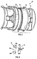
- Figure 2 is an exploded view of a portion of the actuator of Figure 1 .
- Figure 3 shows a protrusion and an indentation of an attachment mechanism used in the actuator of Figures 1 and 2 .
- Figure 4 is a cross-sectional view of another attachment mechanism according to the invention.
- Figure 5 is a cross-sectional view of a further actuator for a brake assembly according to the invention.
- Figure 6 is a detailed cross-sectional view of a portion of the actuator of Figure 5 that shows a retaining ring.
- Figure 7 is a detailed partial cross-sectional view of the actuator of Figure 1 that shows the sealing ribs, which are disposed at the ends of the diaphragm, respectively.
- Figures 1 and 2 show portions of an air-operated (pneumatic) actuator for a brake system.
- the actuator 10 includes a housing 12, a piston 14 moveably disposed in the housing 12, and an elastic diaphragm 16 that seals the gap between the housing 12 and the piston 14.
- a portion of the housing 12 not only is defined by a cylindrical outer wall 18 but also has a cylindrical inner wall 20, which occupies a portion of the housing's inner space.
- the inner wall 20 does not interfere with the movement of the piston 14, because the piston 14 is hollow and the inner wall 20 can extend into the piston 12.
- the outer circumferential wall 22 of the piston 14, on the other hand, can extend into the space between the outer and inner walls 18, 20 of the housing 12.
- the outer and inner walls 18, 20 of the housing 12, the piston 14, and the diaphragm 16 define an air chamber 24 for receiving compressed air, which can move the piston 14 relative to the housing 12.
- the housing and piston of the present invention can each have any suitable configuration.
- the housing may be a simple hollow cylinder
- the piston may be a solid cylinder or a circular plate, which can move axially inside the hollow cylindrical housing.
- the actuator 10 includes an attachment mechanism for attaching the diaphragm 16 to the piston 14.
- This attachment mechanism includes a plurality of protrusions 26 and a plurality of cavities 28, wherein each protrusion 26 is inserted, or is insertable, into a corresponding indentation 28 to secure the diaphragm 16 to the piston 14.
- the term "indentation” as used herein includes a through hole.
- the protrusions 26 are arranged on the piston 14 and the cavities 28 are arranged on the diaphragm 16, although the protrusions may be arranged on the diaphragm and the cavities may be arranged on the piston.
- each protrusion 26 of the attachment mechanism has a bottom portion 26a and a top portion 26b that is wider than the bottom portion 26a, and each cavity 28 (a through hole in this embodiment) includes a top portion 28a and a bottom portion 28b that is wider than the top portion 28a of the cavity 28.
- the elastic diaphragm is integrally molded on the piston.
- the portion of the piston for attaching the diaphragm is configured so that the diaphragm can be securely molded thereto.
- the piston may have the protrusions 26 of Figure 2 , and the diaphragm may be integrally molded on the protrusions 26.
- the piston may have the cavities 28, and the diaphragm may be integrally molded into the cavities 28.
- the cavities of the piston may be through holes, and the diaphragm material can enter each hole through both of its openings to ensure the hole is filled with the diaphragm material. The process of integral molding itself is well known in the art and will not be discussed in detail here.
- Figure 4 shows another embodiment of the attachment mechanism.
- the attachment mechanism includes a plurality of protrusions 126 arranged on the piston 112, which are similar to those shown in Figures 1 and 2 , and a plurality of elastic tubular members 128 on the diaphragm 116.
- the protrusions 126 of the piston 112 can be extended into the respective tubular members 128 of the diaphragm 116 to secure the diaphragm 116 to the piston 112.
- the inner space of each tubular member 128 can be considered as an cavity on the diaphragm 116, into which a protrusion 126 of the piston 112 can extend.
- the inner space of the tubular member 128 is smaller than the protrusion 126 when the tubular member 128 is not mounted on the protrusion 126.
- the elasticity of the tubular member 128 allows the tubular member 128 to expand and secures the tubular member 128 to the protrusion 126.
- the protrusions and cavities of the attachment mechanism can be arranged at any suitable location on the piston and diaphragm.
- the protrusions 26 are arranged at the end of the piston's outer cylindrical wall 22 and extend in the axial direction.
- the cavities 28 are arranged on a raised edge 30 of the diaphragm 16 and also extend in the axial direction.
- the raised edge 30 has alsficient volume to accommodate the cavities 28.
- either or both of the protrusions and the cavities can extend in any other direction, such as the radial direction.
- a retaining ring is used to attach a brake actuator's diaphragm to its piston.
- This retaining ring is different from conventional retaining rings used in brake actuators in that it need not be precisely made.
- the retaining ring 232 has a U-shaped cross-section with two legs 232a, 232b.
- a raised edge 230 of the diaphragm 216 and the end 234 of the piston 214 are clamped between the two legs 232a, 232b to attach the diaphragm 216 to the piston 214.
- the diaphragm 216 has two ribs 236 that are pressed against a radially extending flange 238 of the piston 214 to seal the diaphragm 216 against the piston 214.
- the retaining ring 232 shown in Figures 5 and 6 need not be precisely made because, in contrast to conventional retaining rings used in brake actuators, it does not rely on its dimension, such as the inner or outer diameter, to attach the diaphragm to the piston. Instead the ring 232 clamps the diaphragm and the piston together for attachment. If a conventional retaining ring is not precisely made, it may compress the diaphragm against the piston either insufficiently for a proper attachment and seal, or excessively, damaging the diaphragm or at least making it difficult to mount the retaining ring on the diaphragm.
- FIG. 7 illustrates such a sealing mechanism 40.
- the diaphragm 16 has a generally cylindrical configuration and, in the position shown in Figure 7 , is concentrically arranged with the piston 14.
- the diaphragm 16 includes two ribs 42 on its inner surface 44, each rib 42 forming a generally circular ring on the surface 44, although it may have one rib or more than two ribs.
- the ribs 42 are pressed against the outer surface 46 of the piston 14 by the elasticity of the diaphragm 16 and/or of the ribs 42.
- the ribs 42 or the area of the diaphragm 16, on which the ribs 42 are arranged are smaller than the outer diameter of the area of the piston, on which the ribs 42 are to be pressed against.
- the ribs 42 or the area of the diaphragm 16 is stretched so that the elasticity of the ribs 42 or of the diaphragm 16 presses the ribs 42 against the outer surface 46 of the piston 14 to form a secure seal.
- the compressed air further presses the ribs 42 against the outer surface 46 of the piston 14.
- the housing 112 includes a base 112a and a cap 112b connected to the base 112a.
- the base 112a has a circular ridge 113
- the cap 112b is deformed around the circular ridge 113 to form the connection between the base 112a and the cap 112b.
- the diaphragm 116 has a second raised edge 148 that is compressed between the base 112a and cap 112b of the housing 112.
- the second raised edge 148 of the diaphragm 116 has a rib 150 that is compressed against a ramp 152 of the base 112a to provide a secure seal.
Landscapes
- Engineering & Computer Science (AREA)
- General Engineering & Computer Science (AREA)
- Mechanical Engineering (AREA)
- Transportation (AREA)
- Physics & Mathematics (AREA)
- Fluid Mechanics (AREA)
- Braking Arrangements (AREA)
- Diaphragms And Bellows (AREA)
- Actuator (AREA)
- Braking Systems And Boosters (AREA)
Abstract
Description
- The invention relates to an actuator for a brake system and a method for making a brake actuator.
- Vehicles, particularly commercial vehicles, such as trucks and buses, typically utilize preventive braking system. Such preventive brake systems typically include an air-operated actuator for applying the brake itself, such as a disc or drum type brake. An example of an air operated actuator is a spring-type brake actuator, wherein the actuator includes a spring, which is compressed by the compressed air, and the compressed spring applies the brake when the compressed air is released for parking or emergency situations.
- The spring brake actuator includes a housing (or cylinder), a spring pressure plate (or piston) moveably disposed in the housing, and a diaphragm that is sealingly attached to the housing and the spring pressure plate (or the parking piston). Thus, the diaphragm functions as a seal between the housing and the spring pressure plate. The housing, pressure plate and diaphragm define an air chamber for receiving compressed air. The compressed air inside the air chamber pushes against the spring pressure plate to compress the spring.
- Typically, the diaphragm is attached to, and sealed against, the spring pressure plate with a retaining ring, which is mounted on the diaphragm and presses the diaphragm against the pressure plate. The retaining ring must be made with precision. If the ring is too small, it may be difficult to mount the ring on the diaphragm, or the ring may damage the diaphragm. If it is too large, the ring may not press the diaphragm against the pressure plate sufficiently for a secure attachment and seal. As a result, the retaining ring is relatively expensive.
-
US 5,771,774 discloses an air-operated diaphragm spring brake actuator according to the preamble ofclaims 1 and 6 comprising piston protrusions which pass through a diaphragm and interact with a separate retaining plate to retain the diaphragm -
GB 2,088,525 A -
EP 0 704 361 A1 discloses a perforate diaphragm alignment system for spring brake actuators comprising a diaphragm which is captured at its center by washers and a bolt which passes through the diaphragm into a push rod. - The problem of the invention is solved by the features of
claims 1 and 6. Preferred embodiments are the subject matter of the subclaims. - The invention provides an actuator for a brake system and a method for making a brake actuator, wherein a retaining ring is not required to attach the diaphragm to the piston (or the spring pressure plate) securely and sealingly. Alternatively, the present invention provides a retaining ring that need not be precisely made and yet can attach the diaphragm to the piston securely and sealingly. Therefore, the present invention overcomes the disadvantages associated with the prior art.
- Each protrusion preferably includes a bottom portion and a top portion that is larger than the bottom portion, and each indentation preferably includes a top portion and a bottom portion that is larger than the top portion. (As used herein, the word "larger" means larger in size, such as diameter, length, width, thickness, or volume.) When each protrusion is inserted into the corresponding indentation, the bottom portion of the protrusion may engage the top portion of the corresponding indentation, and the top portion of the protrusion may engage the bottom portion of the corresponding indentation. This arrangement provides a more secure attachment.
- In one preferred embodiment, the diaphragm includes a plurality of elastic tubular members, each of which can be mounted on a protrusion on the piston. For each tubular member and the corresponding protrusion, the inner space of the tubular member may be smaller than the protrusion when the tubular member is not mounted on the protrusion. When the tubular member is mounted on the protrusion, the elasticity of the tubular member allows the tubular member to expand, and securely attaches the tubular member to the protrusion.
- In a preferred embodiment, the method includes the acts of making each protrusion with a bottom portion and a top portion that is larger than the bottom portion, and making each indentation with a top portion and a bottom portion that is larger than the top portion of the indentation. When each protrusion is inserted into the corresponding indentation, the bottom portion of the protrusion engages the top portion of the corresponding indentation, and the top portion of the protrusion engages the bottom portion of the corresponding indentation. In another preferred embodiment, the diaphragm is provided with a plurality of elastic tubular members. For each tubular member and the corresponding protrusion, the inner space of the tubular member preferably is made smaller than the protrusion when the tubular member is not mounted on the protrusion. As a result, when the tubular member is mounted on the protrusion, the elasticity of the tubular member allows the tubular member to expand and secures the tubular member to the protrusion.
- In the embodiments described above, the diaphragm of the brake actuator is attached to the piston of the brake actuator without the use of a retaining ring. As a result, the costs associated with the manufacturing, transporting, and storing the retaining ring are avoided.
- Other objects, advantages and novel features of the present invention will become apparent from the following detailed description of the invention when considered in conjunction with the accompanying drawings.
-
Figure 1 is a partial cross-sectional view of an actuator for a brake system according to the invention. -
Figure 2 is an exploded view of a portion of the actuator ofFigure 1 . -
Figure 3 shows a protrusion and an indentation of an attachment mechanism used in the actuator ofFigures 1 and2 . -
Figure 4 is a cross-sectional view of another attachment mechanism according to the invention. -
Figure 5 is a cross-sectional view of a further actuator for a brake assembly according to the invention. -
Figure 6 is a detailed cross-sectional view of a portion of the actuator ofFigure 5 that shows a retaining ring. -
Figure 7 is a detailed partial cross-sectional view of the actuator ofFigure 1 that shows the sealing ribs, which are disposed at the ends of the diaphragm, respectively. -
Figures 1 and2 show portions of an air-operated (pneumatic) actuator for a brake system. Theactuator 10 includes ahousing 12, apiston 14 moveably disposed in thehousing 12, and anelastic diaphragm 16 that seals the gap between thehousing 12 and thepiston 14. - In this embodiment, a portion of the
housing 12 not only is defined by a cylindricalouter wall 18 but also has a cylindricalinner wall 20, which occupies a portion of the housing's inner space. Theinner wall 20 does not interfere with the movement of thepiston 14, because thepiston 14 is hollow and theinner wall 20 can extend into thepiston 12. The outercircumferential wall 22 of thepiston 14, on the other hand, can extend into the space between the outer andinner walls housing 12. The outer andinner walls housing 12, thepiston 14, and thediaphragm 16 define anair chamber 24 for receiving compressed air, which can move thepiston 14 relative to thehousing 12. In general, however, the housing and piston of the present invention can each have any suitable configuration. For example, the housing may be a simple hollow cylinder, and the piston may be a solid cylinder or a circular plate, which can move axially inside the hollow cylindrical housing. - As shown in
Figure 2 , theactuator 10 includes an attachment mechanism for attaching thediaphragm 16 to thepiston 14. This attachment mechanism includes a plurality ofprotrusions 26 and a plurality ofcavities 28, wherein eachprotrusion 26 is inserted, or is insertable, into acorresponding indentation 28 to secure thediaphragm 16 to thepiston 14. The term "indentation" as used herein includes a through hole. In this embodiment, theprotrusions 26 are arranged on thepiston 14 and thecavities 28 are arranged on thediaphragm 16, although the protrusions may be arranged on the diaphragm and the cavities may be arranged on the piston. - In a preferred embodiment shown in
Figure 3 , eachprotrusion 26 of the attachment mechanism has a bottom portion 26a and atop portion 26b that is wider than the bottom portion 26a, and each cavity 28 (a through hole in this embodiment) includes a top portion 28a and abottom portion 28b that is wider than the top portion 28a of thecavity 28. When theprotrusion 26 is inserted into thecavity 28, the bottom portion 26a of theprotrusion 26 engages the top portion 28a of thecavity 28, and thetop portion 26b of theprotrusion 26 engages thebottom portion 28b of thecavity 28. With this arrangement, theprotrusion 26 can be securely locked inside thecavity 28. - In accordance with another aspect of the invention, the elastic diaphragm is integrally molded on the piston. Preferably, the portion of the piston for attaching the diaphragm is configured so that the diaphragm can be securely molded thereto. For example, the piston may have the
protrusions 26 ofFigure 2 , and the diaphragm may be integrally molded on theprotrusions 26. Alternatively, the piston may have thecavities 28, and the diaphragm may be integrally molded into thecavities 28. In some cases, the cavities of the piston may be through holes, and the diaphragm material can enter each hole through both of its openings to ensure the hole is filled with the diaphragm material. The process of integral molding itself is well known in the art and will not be discussed in detail here. -
Figure 4 shows another embodiment of the attachment mechanism. In this embodiment, the attachment mechanism includes a plurality ofprotrusions 126 arranged on thepiston 112, which are similar to those shown inFigures 1 and2 , and a plurality of elastictubular members 128 on thediaphragm 116. Theprotrusions 126 of thepiston 112 can be extended into the respectivetubular members 128 of thediaphragm 116 to secure thediaphragm 116 to thepiston 112. Analogous to the attachment mechanism shown inFigures 1 and2 , the inner space of eachtubular member 128 can be considered as an cavity on thediaphragm 116, into which aprotrusion 126 of thepiston 112 can extend. Preferably, the inner space of thetubular member 128 is smaller than theprotrusion 126 when thetubular member 128 is not mounted on theprotrusion 126. When thetubular member 128 is mounted on theprotrusion 126, the elasticity of thetubular member 128 allows thetubular member 128 to expand and secures thetubular member 128 to theprotrusion 126. - The protrusions and cavities of the attachment mechanism can be arranged at any suitable location on the piston and diaphragm. In the embodiment shown in
Figures 1 and2 , for example, theprotrusions 26 are arranged at the end of the piston's outercylindrical wall 22 and extend in the axial direction. Thecavities 28 are arranged on a raisededge 30 of thediaphragm 16 and also extend in the axial direction. The raisededge 30 has aufficient volume to accommodate thecavities 28. Alternatively, either or both of the protrusions and the cavities can extend in any other direction, such as the radial direction. - In accordance with a further aspect of the invention, a retaining ring is used to attach a brake actuator's diaphragm to its piston. This retaining ring, however, is different from conventional retaining rings used in brake actuators in that it need not be precisely made. As shown in
Figures 5 and 6 , the retainingring 232 has a U-shaped cross-section with twolegs 232a, 232b. A raisededge 230 of thediaphragm 216 and theend 234 of thepiston 214 are clamped between the twolegs 232a, 232b to attach thediaphragm 216 to thepiston 214. Thediaphragm 216 has tworibs 236 that are pressed against aradially extending flange 238 of thepiston 214 to seal thediaphragm 216 against thepiston 214. - The retaining
ring 232 shown inFigures 5 and 6 . need not be precisely made because, in contrast to conventional retaining rings used in brake actuators, it does not rely on its dimension, such as the inner or outer diameter, to attach the diaphragm to the piston. Instead thering 232 clamps the diaphragm and the piston together for attachment. If a conventional retaining ring is not precisely made, it may compress the diaphragm against the piston either insufficiently for a proper attachment and seal, or excessively, damaging the diaphragm or at least making it difficult to mount the retaining ring on the diaphragm. - Although the above-discussed attachment mechanisms often provide an adequate seal between the diaphragm and the piston, it may be desirable in certain cases to provide a separate sealing mechanism to ensure that the diaphragm is securely sealed against the piston.
Figure 7 illustrates such asealing mechanism 40. In the actuator shown inFigure 7 , thediaphragm 16 has a generally cylindrical configuration and, in the position shown inFigure 7 , is concentrically arranged with thepiston 14. Thediaphragm 16 includes tworibs 42 on itsinner surface 44, eachrib 42 forming a generally circular ring on thesurface 44, although it may have one rib or more than two ribs. - The
ribs 42 are pressed against theouter surface 46 of thepiston 14 by the elasticity of thediaphragm 16 and/or of theribs 42. When thediaphragm 16 is not attached to thepiston 14, theribs 42 or the area of thediaphragm 16, on which theribs 42 are arranged, are smaller than the outer diameter of the area of the piston, on which theribs 42 are to be pressed against. When thediaphragm 16 is attached to thepiston 14 as shown inFigure 7 , theribs 42 or the area of thediaphragm 16 is stretched so that the elasticity of theribs 42 or of thediaphragm 16 presses theribs 42 against theouter surface 46 of thepiston 14 to form a secure seal. Furthermore, when theair chamber 24 is filled with compressed air, the compressed air further presses theribs 42 against theouter surface 46 of thepiston 14. - The diaphragm is also attached to and sealed against the housing of the actuator. In the embodiment shown in
Figure 4 , for example, thehousing 112 includes a base 112a and acap 112b connected to the base 112a. Preferably, the base 112a has acircular ridge 113, and thecap 112b is deformed around thecircular ridge 113 to form the connection between the base 112a and thecap 112b. Thediaphragm 116 has a second raisededge 148 that is compressed between the base 112a andcap 112b of thehousing 112. As a result, thediaphragm 116 is attached to and sealed against thehousing 112. Preferably, as shown inFigure 7 , the second raisededge 148 of thediaphragm 116 has arib 150 that is compressed against aramp 152 of the base 112a to provide a secure seal.
Claims (10)
- An actuator for a brake system comprising:- a housing (12);- a piston (14, 112) movably disposed in the housing (12) comprising an outer cylindrical wall (22);- an elastic diaphragm (16, 116) for providing a seal between the housing (12) and the piston (14, 112); and- an attachment mechanism configured to attach the diaphragm (16, 116) to the piston (14, 112), wherein the attachment mechanism includes a plurality of protrusions (26, 126) on one of the piston (14, 112) and diaphragm (16, 116) and a plurality of cavities ((28, 128) on the other of the piston and diaphragm (16, 116) ;characterized by- the protrusions (26, 126) being arranged at the end of the piston's outer cylindrical wall (22) and extending in the axial direction and by each protrusion (26, 126) being insertable into a corresponding cavity (28, 128) to attach the diaphragm (16, 116) to a radially outer region of the piston (14, 112).
- The actuator of claim 1, wherein each protrusion (26, 126)includes a bottom portion and a top portion that is larger than the bottom portion, wherein each cavity (28, 128) includes a top portion (26a) and a bottom portion (26b) that is larger than the top portion of the cavity (28, 128), and wherein when each protrusion (26, 126)is inserted into the corresponding cavity (28, 128), the bottom portion of the protrusion (26, 126)engages the top portion of the corresponding cavity (28, 128), and the top portion of the protrusion (26, 126)engages the bottom portion of the corresponding cavity (28, 128).
- The actuator of claim 1, wherein the protrusions (26, 126)are on the piston and the cavities are on the diaphragm (16, 116) , and wherein the diaphragm (16, 116) includes a plurality of elastic tubular members (128), each cavity (28, 128) of the diaphragm (16, 116) being defined by the inner space of one of the tubular members.
- The actuator of claim 3, wherein for each tubular member and the corresponding protrusion, the inner space of the tubular member is smaller than the protrusion (26, 126) when the tubular member (128) is not mounted on the protrusion, and wherein when the tubular member is mounted on the protrusion, the elasticity of the tubular member allows the tubular member to expand and secures the tubular member to the protrusion.
- The actuator of claim 1, further comprising a sealing mechanism for providing a seal between the diaphragm (16, 116) and the piston, wherein the sealing mechanism includes a rib-shaped portion of the diaphragm (16, 116) , the rib being pressed against an area of the piston to provide the seal between the diaphragm (16, 116) and the piston, wherein when the diaphragm (16, 116) is not attached to the piston, the rib of the sealing mechanism is smaller than the area of the piston, against which the rib is pressed, and wherein when the diaphragm (16, 116) is attached to the piston, the rib of the sealing mechanism is stretched to the size of the area of the piston, causing the rib to be pressed against the area of the piston.
- A method of making a brake actuator comprising a housing (12), a piston (14, 112) comprising an outer cylindrical wall (22) and being moveably disposed in the housing (12), and an elastic diaphragm (16, 116) for providing a seal between the housing (12) and the piston (14, 112), the method comprising the acts of attaching the elastic diaphragm (16, 116) to a radially outer region of the piston by inserting each of a plurality of protrusions (26, 126) being arranged at the end of the piston's outer cylindrical wall (22) and extending in the axial direction on one of the piston (14, 112) and diaphragm (16, 116) protrusion into a corresponding one of a plurality of cavities on the other of the piston (14, 112) and diaphragm (16, 116).
- The method of claim 6, further comprising the acts of: making each protrusion (26, 126)with a bottom portion and a top portion that is larger than the bottom portion; and making each cavity (28, 128) with a top portion and a bottom portion that is larger than the top portion of the cavity (28, 128), wherein when each protrusion (26, 126)is inserted into the corresponding cavity (28, 128), the bottom portion of the protrusion (26, 126)engages the top portion of the corresponding cavity (28, 128), and the top portion of the protrusion (26, 126)engages the bottom portion of the corresponding cavity (28, 128).
- The method of claim 6, wherein the plurality of protrusions (26, 126)are on the piston and the plurality of cavities are on the diaphragm (16, 116) , the method further comprising providing the diaphragm (16, 116) with a plurality of elastic tubular members (128) , each cavity (28, 128) of the diaphragm (16, 116) being defined by the inner space of one of the tubular members.
- The method of claim 8, further comprising, for each tubular member and the corresponding protrusion, making the inner space of the tubular member smaller than the protrusion (26, 126) when the tubular member is not mounted on the protrusion, so that when the tubular member is mounted on the protrusion, the elasticity of the tubular member allows the tubular member to expand and secures the tubular member to the protrusion.
- The method of claim 6, further comprising the acts of providing the diaphragm (16, 116) with a rib-shaped portion; pressing the rib against an area of the piston to provide a seal between the diaphragm (16, 116) and the piston; making the rib smaller than the area of the piston, against which the rib is pressed, when the diaphragm (16, 116) is not attached to the piston; and attaching the diaphragm (16, 116) to the piston so that the rib of the sealing mechanism is stretched to the size of the area of the piston, causing the rib to be pressed against the area of the piston.
Priority Applications (2)
| Application Number | Priority Date | Filing Date | Title |
|---|---|---|---|
| PL06015140T PL1746003T3 (en) | 2005-07-22 | 2006-07-20 | Actuator for a brake system and method of making a brake actuator |
| EP09174475.5A EP2143609A3 (en) | 2005-07-22 | 2006-07-20 | Actuator for a brake system and method of making a brake actuator |
Applications Claiming Priority (1)
| Application Number | Priority Date | Filing Date | Title |
|---|---|---|---|
| US11/187,005 US7343847B2 (en) | 2005-07-22 | 2005-07-22 | Actuator for a brake system and method of making a brake actuator |
Related Child Applications (1)
| Application Number | Title | Priority Date | Filing Date |
|---|---|---|---|
| EP09174475.5A Division EP2143609A3 (en) | 2005-07-22 | 2006-07-20 | Actuator for a brake system and method of making a brake actuator |
Publications (2)
| Publication Number | Publication Date |
|---|---|
| EP1746003A1 EP1746003A1 (en) | 2007-01-24 |
| EP1746003B1 true EP1746003B1 (en) | 2010-01-06 |
Family
ID=37022078
Family Applications (2)
| Application Number | Title | Priority Date | Filing Date |
|---|---|---|---|
| EP09174475.5A Withdrawn EP2143609A3 (en) | 2005-07-22 | 2006-07-20 | Actuator for a brake system and method of making a brake actuator |
| EP06015140A Not-in-force EP1746003B1 (en) | 2005-07-22 | 2006-07-20 | Actuator for a brake system and method of making a brake actuator |
Family Applications Before (1)
| Application Number | Title | Priority Date | Filing Date |
|---|---|---|---|
| EP09174475.5A Withdrawn EP2143609A3 (en) | 2005-07-22 | 2006-07-20 | Actuator for a brake system and method of making a brake actuator |
Country Status (8)
| Country | Link |
|---|---|
| US (1) | US7343847B2 (en) |
| EP (2) | EP2143609A3 (en) |
| AT (1) | ATE454299T1 (en) |
| AU (1) | AU2006203102B2 (en) |
| BR (1) | BRPI0602884A (en) |
| CA (1) | CA2552775C (en) |
| DE (1) | DE602006011540D1 (en) |
| PL (1) | PL1746003T3 (en) |
Families Citing this family (11)
| Publication number | Priority date | Publication date | Assignee | Title |
|---|---|---|---|---|
| US7451690B2 (en) * | 2005-07-20 | 2008-11-18 | Wabco Gmbh | Spring-actuated air-brake cylinder for vehicle brake systems |
| WO2009075659A2 (en) * | 2007-12-11 | 2009-06-18 | Orsan Ticari Arac Sistemleri Ltd. Sti. | Emergency chamber locking mechanism in the bellows with diaphragm and piston |
| GB2458544B (en) * | 2008-07-08 | 2011-06-08 | Malory Maltby | Variable radius lever arm assembly |
| USD601933S1 (en) * | 2008-07-10 | 2009-10-13 | Wabco Gmbh | Split cylinder actuator |
| USD627694S1 (en) * | 2008-07-10 | 2010-11-23 | Wabco Gmbh | Transmission range cylinder |
| USD600179S1 (en) * | 2008-07-10 | 2009-09-15 | Wabco Gmbh | Gearbox actuator |
| USD600180S1 (en) * | 2008-07-10 | 2009-09-15 | Wabco Gmbh | Clutch actuator |
| USD659614S1 (en) * | 2010-05-14 | 2012-05-15 | Wabco Gmbh | Pneumatic clutch actuator |
| US9004236B2 (en) | 2011-09-28 | 2015-04-14 | Bendix Spicer Foundation Brake, Llc | Parking brake piston for a parking brake chamber |
| CA3024391C (en) | 2016-05-20 | 2023-06-20 | Haldex Brake Products Corporation | Spring brake actuator with diaphragm retainer |
| EP3992488A1 (en) * | 2020-10-30 | 2022-05-04 | ZF CV Systems Europe BV | Pneumatic service brake actuator |
Family Cites Families (7)
| Publication number | Priority date | Publication date | Assignee | Title |
|---|---|---|---|---|
| GB2008525A (en) | 1977-11-24 | 1979-06-06 | Conveyor Units Ltd | Improvements relating to live roller conveyors |
| GB2088525A (en) * | 1980-11-18 | 1982-06-09 | Bendix Ltd | Diaphragm-pressure plate connection in fluid pressure actuator. |
| US5507217A (en) | 1994-09-30 | 1996-04-16 | Indian Head Industries, Inc. | Perforate diaphragm alignment system for spring brake actuators |
| DE19623099C1 (en) * | 1996-06-10 | 1997-10-16 | Contitech Formteile Gmbh | Brake membrane for pressure medium, spring-brake cylinder |
| US5771774A (en) * | 1996-10-09 | 1998-06-30 | Nai Anchorlok, Inc. | Spring brake actuator having plastic pressure plate assembly |
| US6212996B1 (en) * | 1999-06-25 | 2001-04-10 | Longwood Industries, Inc. | Thin-walled brake diaphragm |
| US6360649B1 (en) * | 2000-04-26 | 2002-03-26 | Indian Head Industries, Inc. | Spring brake actuator |
-
2005
- 2005-07-22 US US11/187,005 patent/US7343847B2/en not_active Expired - Lifetime
-
2006
- 2006-07-20 DE DE602006011540T patent/DE602006011540D1/en active Active
- 2006-07-20 CA CA2552775A patent/CA2552775C/en active Active
- 2006-07-20 EP EP09174475.5A patent/EP2143609A3/en not_active Withdrawn
- 2006-07-20 EP EP06015140A patent/EP1746003B1/en not_active Not-in-force
- 2006-07-20 AT AT06015140T patent/ATE454299T1/en active
- 2006-07-20 PL PL06015140T patent/PL1746003T3/en unknown
- 2006-07-21 BR BRPI0602884-5A patent/BRPI0602884A/en not_active IP Right Cessation
- 2006-07-21 AU AU2006203102A patent/AU2006203102B2/en not_active Ceased
Also Published As
| Publication number | Publication date |
|---|---|
| CA2552775C (en) | 2014-09-30 |
| EP2143609A3 (en) | 2014-07-30 |
| DE602006011540D1 (en) | 2010-02-25 |
| ATE454299T1 (en) | 2010-01-15 |
| PL1746003T3 (en) | 2010-06-30 |
| US20070017365A1 (en) | 2007-01-25 |
| EP1746003A1 (en) | 2007-01-24 |
| US7343847B2 (en) | 2008-03-18 |
| EP2143609A2 (en) | 2010-01-13 |
| AU2006203102A1 (en) | 2007-02-08 |
| BRPI0602884A (en) | 2007-03-13 |
| CA2552775A1 (en) | 2007-01-22 |
| AU2006203102B2 (en) | 2012-03-08 |
Similar Documents
| Publication | Publication Date | Title |
|---|---|---|
| EP0575830B1 (en) | Tamper-resistant brake actuator | |
| US5105727A (en) | Spring brake actuator with an annular edge of a diaphragm sealed between a tubular part of a pressure plate and an actuator rod | |
| US6006651A (en) | Spring brake actuator with filtered service vent opening | |
| EP1624154B1 (en) | Brake actuator | |
| US5771774A (en) | Spring brake actuator having plastic pressure plate assembly | |
| CN102159437A (en) | Combined service brake and spring energy storage brake cylinder comprising sealing assemblies consisting of guide ring and at least one sealing element | |
| CA2552775C (en) | Actuator for a brake system and method of making a brake actuator | |
| JPH03505715A (en) | Negative pressure braking force booster for automobiles | |
| CN109311465A (en) | Spring Brake Actuator with Diaphragm Retainer | |
| EP4015323A2 (en) | Spring brake actuator for use in a commercial vehicle and commercial vehicle comprising the same | |
| JP2004521815A (en) | Radially sealed air brake chamber | |
| CA2278611A1 (en) | Brake actuator with self-centering diaphragm | |
| WO1995000746A1 (en) | Spring brake actuator with a pressure plate bearing for a caging tool | |
| EP3831677B1 (en) | Spring brake actuator | |
| US6988442B2 (en) | Air brake diaphragms which resist pull-out | |
| US6223647B1 (en) | Brake actuator and method of forming same | |
| US6357337B1 (en) | Spring brake actuator with sealed chamber and method for sealing | |
| WO1996014231A1 (en) | Spring brake actuator with guide and bearing for an actuator rod | |
| EP4282722B1 (en) | Piston boot for a brake actuator, brake actuator comprising a respective piston boot and a disc brake | |
| AU709256B2 (en) | Spring brake actuator having plastic pressure plate assembly | |
| MXPA06008287A (en) | Actuator for a brake system and method of making a brake actuator | |
| EP1192071B1 (en) | Service brake actuator having a unitary pushrod assembly with a bushing therefor | |
| MXPA98003781A (en) | Spring brake actuator having plast pressure plug assembly |
Legal Events
| Date | Code | Title | Description |
|---|---|---|---|
| PUAI | Public reference made under article 153(3) epc to a published international application that has entered the european phase |
Free format text: ORIGINAL CODE: 0009012 |
|
| AK | Designated contracting states |
Kind code of ref document: A1 Designated state(s): AT BE BG CH CY CZ DE DK EE ES FI FR GB GR HU IE IS IT LI LT LU LV MC NL PL PT RO SE SI SK TR |
|
| AX | Request for extension of the european patent |
Extension state: AL BA HR MK YU |
|
| RAP1 | Party data changed (applicant data changed or rights of an application transferred) |
Owner name: BENDIX SPICER FOUNDATION BRAKE LLC |
|
| 17P | Request for examination filed |
Effective date: 20070609 |
|
| 17Q | First examination report despatched |
Effective date: 20070705 |
|
| AKX | Designation fees paid |
Designated state(s): AT BE BG CH CY CZ DE DK EE ES FI FR GB GR HU IE IS IT LI LT LU LV MC NL PL PT RO SE SI SK TR |
|
| GRAP | Despatch of communication of intention to grant a patent |
Free format text: ORIGINAL CODE: EPIDOSNIGR1 |
|
| GRAS | Grant fee paid |
Free format text: ORIGINAL CODE: EPIDOSNIGR3 |
|
| GRAA | (expected) grant |
Free format text: ORIGINAL CODE: 0009210 |
|
| AK | Designated contracting states |
Kind code of ref document: B1 Designated state(s): AT BE BG CH CY CZ DE DK EE ES FI FR GB GR HU IE IS IT LI LT LU LV MC NL PL PT RO SE SI SK TR |
|
| REG | Reference to a national code |
Ref country code: GB Ref legal event code: FG4D |
|
| REG | Reference to a national code |
Ref country code: CH Ref legal event code: EP |
|
| REG | Reference to a national code |
Ref country code: IE Ref legal event code: FG4D |
|
| REF | Corresponds to: |
Ref document number: 602006011540 Country of ref document: DE Date of ref document: 20100225 Kind code of ref document: P |
|
| REG | Reference to a national code |
Ref country code: NL Ref legal event code: T3 |
|
| PG25 | Lapsed in a contracting state [announced via postgrant information from national office to epo] |
Ref country code: SI Free format text: LAPSE BECAUSE OF FAILURE TO SUBMIT A TRANSLATION OF THE DESCRIPTION OR TO PAY THE FEE WITHIN THE PRESCRIBED TIME-LIMIT Effective date: 20100106 |
|
| LTIE | Lt: invalidation of european patent or patent extension |
Effective date: 20100106 |
|
| PG25 | Lapsed in a contracting state [announced via postgrant information from national office to epo] |
Ref country code: PT Free format text: LAPSE BECAUSE OF FAILURE TO SUBMIT A TRANSLATION OF THE DESCRIPTION OR TO PAY THE FEE WITHIN THE PRESCRIBED TIME-LIMIT Effective date: 20100506 Ref country code: IS Free format text: LAPSE BECAUSE OF FAILURE TO SUBMIT A TRANSLATION OF THE DESCRIPTION OR TO PAY THE FEE WITHIN THE PRESCRIBED TIME-LIMIT Effective date: 20100506 Ref country code: LT Free format text: LAPSE BECAUSE OF FAILURE TO SUBMIT A TRANSLATION OF THE DESCRIPTION OR TO PAY THE FEE WITHIN THE PRESCRIBED TIME-LIMIT Effective date: 20100106 Ref country code: ES Free format text: LAPSE BECAUSE OF FAILURE TO SUBMIT A TRANSLATION OF THE DESCRIPTION OR TO PAY THE FEE WITHIN THE PRESCRIBED TIME-LIMIT Effective date: 20100417 |
|
| REG | Reference to a national code |
Ref country code: HU Ref legal event code: AG4A Ref document number: E007709 Country of ref document: HU |
|
| PG25 | Lapsed in a contracting state [announced via postgrant information from national office to epo] |
Ref country code: FI Free format text: LAPSE BECAUSE OF FAILURE TO SUBMIT A TRANSLATION OF THE DESCRIPTION OR TO PAY THE FEE WITHIN THE PRESCRIBED TIME-LIMIT Effective date: 20100106 Ref country code: LV Free format text: LAPSE BECAUSE OF FAILURE TO SUBMIT A TRANSLATION OF THE DESCRIPTION OR TO PAY THE FEE WITHIN THE PRESCRIBED TIME-LIMIT Effective date: 20100106 |
|
| PG25 | Lapsed in a contracting state [announced via postgrant information from national office to epo] |
Ref country code: SE Free format text: LAPSE BECAUSE OF FAILURE TO SUBMIT A TRANSLATION OF THE DESCRIPTION OR TO PAY THE FEE WITHIN THE PRESCRIBED TIME-LIMIT Effective date: 20100106 Ref country code: RO Free format text: LAPSE BECAUSE OF FAILURE TO SUBMIT A TRANSLATION OF THE DESCRIPTION OR TO PAY THE FEE WITHIN THE PRESCRIBED TIME-LIMIT Effective date: 20100106 Ref country code: GR Free format text: LAPSE BECAUSE OF FAILURE TO SUBMIT A TRANSLATION OF THE DESCRIPTION OR TO PAY THE FEE WITHIN THE PRESCRIBED TIME-LIMIT Effective date: 20100407 Ref country code: EE Free format text: LAPSE BECAUSE OF FAILURE TO SUBMIT A TRANSLATION OF THE DESCRIPTION OR TO PAY THE FEE WITHIN THE PRESCRIBED TIME-LIMIT Effective date: 20100106 Ref country code: CY Free format text: LAPSE BECAUSE OF FAILURE TO SUBMIT A TRANSLATION OF THE DESCRIPTION OR TO PAY THE FEE WITHIN THE PRESCRIBED TIME-LIMIT Effective date: 20100106 Ref country code: BE Free format text: LAPSE BECAUSE OF FAILURE TO SUBMIT A TRANSLATION OF THE DESCRIPTION OR TO PAY THE FEE WITHIN THE PRESCRIBED TIME-LIMIT Effective date: 20100106 |
|
| PGFP | Annual fee paid to national office [announced via postgrant information from national office to epo] |
Ref country code: HU Payment date: 20100727 Year of fee payment: 5 Ref country code: NL Payment date: 20100726 Year of fee payment: 5 |
|
| PLBE | No opposition filed within time limit |
Free format text: ORIGINAL CODE: 0009261 |
|
| STAA | Information on the status of an ep patent application or granted ep patent |
Free format text: STATUS: NO OPPOSITION FILED WITHIN TIME LIMIT |
|
| PG25 | Lapsed in a contracting state [announced via postgrant information from national office to epo] |
Ref country code: BG Free format text: LAPSE BECAUSE OF FAILURE TO SUBMIT A TRANSLATION OF THE DESCRIPTION OR TO PAY THE FEE WITHIN THE PRESCRIBED TIME-LIMIT Effective date: 20100406 Ref country code: SK Free format text: LAPSE BECAUSE OF FAILURE TO SUBMIT A TRANSLATION OF THE DESCRIPTION OR TO PAY THE FEE WITHIN THE PRESCRIBED TIME-LIMIT Effective date: 20100106 |
|
| PGFP | Annual fee paid to national office [announced via postgrant information from national office to epo] |
Ref country code: CZ Payment date: 20100712 Year of fee payment: 5 Ref country code: FR Payment date: 20100802 Year of fee payment: 5 Ref country code: TR Payment date: 20100714 Year of fee payment: 5 |
|
| 26N | No opposition filed |
Effective date: 20101007 |
|
| PGFP | Annual fee paid to national office [announced via postgrant information from national office to epo] |
Ref country code: GB Payment date: 20100726 Year of fee payment: 5 Ref country code: PL Payment date: 20100712 Year of fee payment: 5 |
|
| PG25 | Lapsed in a contracting state [announced via postgrant information from national office to epo] |
Ref country code: DK Free format text: LAPSE BECAUSE OF FAILURE TO SUBMIT A TRANSLATION OF THE DESCRIPTION OR TO PAY THE FEE WITHIN THE PRESCRIBED TIME-LIMIT Effective date: 20100106 |
|
| PG25 | Lapsed in a contracting state [announced via postgrant information from national office to epo] |
Ref country code: MC Free format text: LAPSE BECAUSE OF NON-PAYMENT OF DUE FEES Effective date: 20100731 |
|
| PGFP | Annual fee paid to national office [announced via postgrant information from national office to epo] |
Ref country code: DE Payment date: 20100922 Year of fee payment: 5 |
|
| REG | Reference to a national code |
Ref country code: CH Ref legal event code: PL |
|
| PG25 | Lapsed in a contracting state [announced via postgrant information from national office to epo] |
Ref country code: IT Free format text: LAPSE BECAUSE OF FAILURE TO SUBMIT A TRANSLATION OF THE DESCRIPTION OR TO PAY THE FEE WITHIN THE PRESCRIBED TIME-LIMIT Effective date: 20100106 |
|
| PG25 | Lapsed in a contracting state [announced via postgrant information from national office to epo] |
Ref country code: CH Free format text: LAPSE BECAUSE OF NON-PAYMENT OF DUE FEES Effective date: 20100731 Ref country code: LI Free format text: LAPSE BECAUSE OF NON-PAYMENT OF DUE FEES Effective date: 20100731 |
|
| PG25 | Lapsed in a contracting state [announced via postgrant information from national office to epo] |
Ref country code: IE Free format text: LAPSE BECAUSE OF NON-PAYMENT OF DUE FEES Effective date: 20100720 |
|
| REG | Reference to a national code |
Ref country code: NL Ref legal event code: V1 Effective date: 20120201 |
|
| GBPC | Gb: european patent ceased through non-payment of renewal fee |
Effective date: 20110720 |
|
| REG | Reference to a national code |
Ref country code: FR Ref legal event code: ST Effective date: 20120330 |
|
| PG25 | Lapsed in a contracting state [announced via postgrant information from national office to epo] |
Ref country code: FR Free format text: LAPSE BECAUSE OF NON-PAYMENT OF DUE FEES Effective date: 20110801 Ref country code: DE Free format text: LAPSE BECAUSE OF NON-PAYMENT OF DUE FEES Effective date: 20120201 Ref country code: CZ Free format text: LAPSE BECAUSE OF NON-PAYMENT OF DUE FEES Effective date: 20110720 Ref country code: HU Free format text: LAPSE BECAUSE OF NON-PAYMENT OF DUE FEES Effective date: 20110721 |
|
| REG | Reference to a national code |
Ref country code: DE Ref legal event code: R119 Ref document number: 602006011540 Country of ref document: DE Effective date: 20120201 |
|
| PG25 | Lapsed in a contracting state [announced via postgrant information from national office to epo] |
Ref country code: NL Free format text: LAPSE BECAUSE OF NON-PAYMENT OF DUE FEES Effective date: 20120201 |
|
| PG25 | Lapsed in a contracting state [announced via postgrant information from national office to epo] |
Ref country code: GB Free format text: LAPSE BECAUSE OF NON-PAYMENT OF DUE FEES Effective date: 20110720 |
|
| PG25 | Lapsed in a contracting state [announced via postgrant information from national office to epo] |
Ref country code: LU Free format text: LAPSE BECAUSE OF NON-PAYMENT OF DUE FEES Effective date: 20100720 |
|
| PG25 | Lapsed in a contracting state [announced via postgrant information from national office to epo] |
Ref country code: PL Free format text: LAPSE BECAUSE OF NON-PAYMENT OF DUE FEES Effective date: 20110720 |
|
| REG | Reference to a national code |
Ref country code: PL Ref legal event code: LAPE |
|
| REG | Reference to a national code |
Ref country code: AT Ref legal event code: MM01 Ref document number: 454299 Country of ref document: AT Kind code of ref document: T Effective date: 20110720 |
|
| PG25 | Lapsed in a contracting state [announced via postgrant information from national office to epo] |
Ref country code: AT Free format text: LAPSE BECAUSE OF NON-PAYMENT OF DUE FEES Effective date: 20110720 |
|
| PG25 | Lapsed in a contracting state [announced via postgrant information from national office to epo] |
Ref country code: TR Free format text: LAPSE BECAUSE OF NON-PAYMENT OF DUE FEES Effective date: 20110720 |