EP1745994A1 - Seat belt retractor, seat belt device, and vehicle with seat belt device - Google Patents
Seat belt retractor, seat belt device, and vehicle with seat belt device Download PDFInfo
- Publication number
- EP1745994A1 EP1745994A1 EP06012677A EP06012677A EP1745994A1 EP 1745994 A1 EP1745994 A1 EP 1745994A1 EP 06012677 A EP06012677 A EP 06012677A EP 06012677 A EP06012677 A EP 06012677A EP 1745994 A1 EP1745994 A1 EP 1745994A1
- Authority
- EP
- European Patent Office
- Prior art keywords
- seat belt
- vehicle
- motor
- spool
- electric motor
- Prior art date
- Legal status (The legal status is an assumption and is not a legal conclusion. Google has not performed a legal analysis and makes no representation as to the accuracy of the status listed.)
- Granted
Links
- 230000033001 locomotion Effects 0.000 claims abstract description 21
- 230000000452 restraining effect Effects 0.000 claims abstract description 14
- 230000003247 decreasing effect Effects 0.000 claims abstract description 8
- 238000001514 detection method Methods 0.000 claims description 7
- 230000005540 biological transmission Effects 0.000 description 30
- 230000007246 mechanism Effects 0.000 description 27
- 238000000034 method Methods 0.000 description 9
- 230000008569 process Effects 0.000 description 9
- 230000006870 function Effects 0.000 description 4
- 230000001133 acceleration Effects 0.000 description 3
- 230000008859 change Effects 0.000 description 3
- 230000002093 peripheral effect Effects 0.000 description 3
- 230000002123 temporal effect Effects 0.000 description 3
- 230000009467 reduction Effects 0.000 description 2
- 238000012986 modification Methods 0.000 description 1
- 230000004048 modification Effects 0.000 description 1
Images


Classifications
-
- B—PERFORMING OPERATIONS; TRANSPORTING
- B60—VEHICLES IN GENERAL
- B60R—VEHICLES, VEHICLE FITTINGS, OR VEHICLE PARTS, NOT OTHERWISE PROVIDED FOR
- B60R22/00—Safety belts or body harnesses in vehicles
- B60R22/34—Belt retractors, e.g. reels
- B60R22/46—Reels with means to tension the belt in an emergency by forced winding up
-
- B—PERFORMING OPERATIONS; TRANSPORTING
- B60—VEHICLES IN GENERAL
- B60R—VEHICLES, VEHICLE FITTINGS, OR VEHICLE PARTS, NOT OTHERWISE PROVIDED FOR
- B60R22/00—Safety belts or body harnesses in vehicles
- B60R22/34—Belt retractors, e.g. reels
- B60R22/44—Belt retractors, e.g. reels with means for reducing belt tension during use under normal conditions
-
- B—PERFORMING OPERATIONS; TRANSPORTING
- B60—VEHICLES IN GENERAL
- B60R—VEHICLES, VEHICLE FITTINGS, OR VEHICLE PARTS, NOT OTHERWISE PROVIDED FOR
- B60R22/00—Safety belts or body harnesses in vehicles
- B60R22/34—Belt retractors, e.g. reels
- B60R22/44—Belt retractors, e.g. reels with means for reducing belt tension during use under normal conditions
- B60R2022/4473—Belt retractors, e.g. reels with means for reducing belt tension during use under normal conditions using an electric retraction device
-
- B—PERFORMING OPERATIONS; TRANSPORTING
- B60—VEHICLES IN GENERAL
- B60R—VEHICLES, VEHICLE FITTINGS, OR VEHICLE PARTS, NOT OTHERWISE PROVIDED FOR
- B60R22/00—Safety belts or body harnesses in vehicles
- B60R22/34—Belt retractors, e.g. reels
- B60R22/46—Reels with means to tension the belt in an emergency by forced winding up
- B60R2022/4666—Reels with means to tension the belt in an emergency by forced winding up characterised by electric actuators
Definitions
- the present invention relates to a seat belt retractor to be mounted in a vehicle.
- Patent Document 1 JP-6-71333 U
- the technology disclosed in the Patent Document 1 employs the structure, which retracts and withdraws the seat belt through a spool by a motor, as a structure of the seat belt retractor.
- the tension of the seat belt is intermittently varied by driving the motor, and thus a restraining force can be varied. Accordingly, it is possible to warn a driver with respect to a vehicle collision.
- the seat belt has an initial slack, and thus a part of the rotation of the motor is used to remove the slack at the time of an initial operation. Accordingly, it is impossible to obtain the desired belt tension that is useful to warn the vehicle occupant.
- the present invention has been made to solve the above-mentioned problem, and it is an object of the present invention to provide an effective technology that is useful to reliably warn a vehicle occupant by using the seat belt of a seat belt retractor mounted in a vehicle to retract / withdraw the seat belt for restraining a vehicle occupant depending on the driving of the electric motor.
- the invention is provided to achieve the above-mentioned problem.
- the invention can be typically applied to a seat belt retractor mounted in a vehicle such as an automobile
- the invention can be applied to a structure of a seat belt retractor that is mounted in a vehicle other than the automobile, for example an airplane, a ship, an electric train, a bus, and so on.
- a first aspect of the invention for solving the above-mentioned problem relates to a seat belt retractor according to claim 1.
- the seat belt retractor according to claim 1 is mounted in a vehicle, and includes at least an electric motor, a spool, and a controller.
- the spool of the present invention is composed of a member that retracts and withdraws the seat belt for restraining a vehicle occupant.
- the seat belt to be retracted or withdrawn with the spool is a long belt to be fastened about a vehicle occupant seated in a seat, and is called as 'webbing'.
- the seat belt is fastened about the vehicle occupant seated in a vehicle seat during the restraint of the vehicle occupant, that is, the vehicle collision. Therefore, the vehicle occupant is restrained.
- a power transmission mechanism is provided between the electric motor and the spool. The power transmission mechanism forms a connecting state in which the electric motor and the spool are connected to each other, and a disconnecting state in which the connecting state is released.
- the controller of the present invention is composed of a unit for controlling at least the electric motor, and controls a driving direction of the electric motor, a driving time, a driving force, and the like.
- the controller is typically composed of a CPU (central processing unit), input and output units, a memory unit, peripheral units, etc.
- the controller may be dedicatedly provided to the seat belt retractor, or may be used as a controller for controlling a driving system or an electrical system of a vehicle as well as the seat belt retractor.
- the controller controls the driving of the electric motor so that several operations for increasing and decreasing the tension acting on the seat belt by the spool are repeated so as to warn the vehicle occupant at the time of fastening of the seat belt to the vehicle occupant (typically, a driver).
- warning is performed in the following cases: in the case of determining that the obstacles (other vehicles, obstacles, pedestrians, etc) around the vehicle are in a predetermined range or the vehicle is highly in danger of colliding with obstacles, or in the case of determining that the driver falls asleep.
- the retractor of the present invention serves as a warning unit (warning system) for warning the vehicle occupant as well as a restraining unit for restraining the vehicle occupant by means of the seat belt.
- the controller controls the driving of the electric motor so that a motion of the spool becomes relatively larger in a seat belt retracting direction in the initial operation of the several operations.
- the 'initial operation' includes a first or several operations of the operations repeated several times.
- the present invention can employ a step in which the motion of the spool in the first operation serving as an 'initial operation' is relatively increased as compared to the motion of the spool at the second or third operation of the first to the third operations, and a step in which the motions of the spool in the first and the second operation serving as 'initial operations' are relatively increased as compared to the motion of the spool at the third operation.
- the number of revolutions of the spool in the initial operation is larger than those in the following operations. Therefore, if the seat belt has an initial slack, it is possible to again generate the tension larger than a desired belt tension useful to warn the vehicle occupant after the slack is removed. In this case, even if the seat belt does not nearly have an initial slack, it goes without saying that the tension larger than the desired belt tension is obtained. Accordingly, it is possible to quickly and reliably warn the vehicle occupant by the seat belt at any one of the retracting operations of the electric motor that is repeated several times.
- a second aspect of the present invention for solving the above-mentioned problem relates to a seat belt retractor according to claim 2.
- the controller of the structure according to claim 1 increases relatively at least one of the motor output or rotation time of the electric motor in the initial operation so that the motion of the spool becomes relatively larger in the seat belt retracting direction.
- the present invention includes a control for relatively increasing at least one of the motor output or rotation time of the electric motor in the first operation, and a control for relatively increasing both the motor output and the rotation time of the motor in the first operation.
- the rotational speed of the motor can be increased by increasing the motor output of the electric motor.
- each of the current value (called as a 'control current value') and the voltage value (called as an 'applied voltage value') in the initial operation is set larger than that of the following operations.
- the seat belt retractor disclosed in claim 2, it is possible to quickly and reliably warn the vehicle occupant by means of the seat belt at any one of the retracting operations of the electric motor which is repeated several times by a control for increasing the motor output or the rotation time of the motor in the first operation.
- a third aspect of the present invention for solving the above-mentioned problem relates to a seat belt device according to claim 3.
- a seat belt device installed on a vehicle according to claim 3 includes at least a seat belt, an electric motor, a spool, a controller, a buckle, a tongue, and a detecting sensor.
- the seat belt of the present invention is a long belt to be fastened to a vehicle occupant seated in a vehicle seat, and is called as 'webbing'.
- the seat belt is fastened about the vehicle occupant seated in a vehicle seat during the restraint of the vehicle occupant, that is, the vehicle collision. Therefore, the vehicle occupant is restrained.
- the buckle of the present invention is composed of a member fixed to the vehicle.
- the tongue of the present invention is composed of a member, which is provided to the seat belt and is engaged with the buckle of the present invention at the time of fastening of the seat belt.
- the detecting sensor of the present invention is composed of a unit for detecting that the tongue is engaged with the buckle.
- the electric motor, the spool, and the controller of the present invention have the substantially same functions as components of the seat belt retractor according to claim 1. That is, the seat belt device of the present invention serves as a warning unit (warning system) for warning the vehicle occupant as well as a restraining unit for restraining the vehicle occupant by means of the seat belt. Furthermore, in the present invention, the controller controls the electric motor so that a motion of the spool becomes relatively larger in a seat belt retracting direction in the initial operation of the operations repeated several times.
- the number of revolutions of the spool in the initial operation is larger than those in the following operations. Therefore, if the seat belt has an initial slack, it is possible to again generate the tension larger than a desired belt tension useful to warn the vehicle occupant after the slack is removed. In this case, even if the seat belt does not nearly have an initial slack, it goes without saying that the tension larger than the desired belt tension is obtained. Accordingly, it is possible to quickly and reliably warn the vehicle occupant by the seat belt at any one of the retracting operations of the electric motor which is repeated several times.
- a fourth aspect of the present invention for solving the above-mentioned problem relates to a seat belt device according to claim 4.
- the controller of the structure according to claim 3 increases relatively at least one of the motor output or rotation time of the electric motor in the initial operation so that the motion of the spool becomes relatively larger in the seat belt retracting direction. Therefore, according to the structure of the seat belt device disclosed in claim 4, it is possible to quickly and reliably warn the vehicle occupant by means of the seat belt at any one of the retracting operations of the electric motor which is repeated several times by a control for increasing the motor output or the rotation time of the motor.
- a fifth aspect of the present invention for solving the above-mentioned problem relates to a vehicle with a seat belt device according to claim 5.
- the vehicle with a seat belt device according to claim 5 includes at least the seat belt device according to claim 3 or 4.
- the seat belt device is accommodated in the accommodating space of the vehicle, for example, the accommodating space within a pillar, the accommodating space within a seat, or the accommodating space of other portions of the vehicle.
- the structure of the vehicle with a seat belt retractor it is possible to provide a vehicle having the seat belt device that can quickly and reliably warn the vehicle occupant by means of the seat belt at any one of the retracting operations of the electric motor repeated several times and is accommodated in the accommodating space of the vehicle.
- the controller controls the electric motor so that a motion of the spool becomes relatively larger in a seat belt retracting direction. Accordingly, it is possible to reliably warn the vehicle occupant by means of the seat belt.
- the seat belt device 100 of the present embodiment is a seat belt device for a vehicle, which is mounted in a vehicle as a 'vehicle with a seat belt device', and includes a seat belt retractor 1, a seat belt 3, a shoulder guider anchor 10, a tongue 12, an outer anchor 14, a buckle 16, and an ECU 20, as main components.
- a vehicle is provided with an input element 30.
- the input element 30 detects various information, such as information about a collision prediction or collision generation of the vehicle, a driving state of the vehicle, a seating position or a physique of a vehicle occupant seated on the seat, surrounding traffic conditions, and weather or time zones. Then, the input element 30 inputs the detection information to the ECU 20.
- the detection information of the input element 30 is transmitted to the ECU 20 at all times or in every predetermined time so that the detection information of the input element 30 can be used for controlling operation of the seat belt device 100 or the like.
- the input element 30 of the present embodiment includes a vehicle collision information detecting sensor 32 for detecting information about a collision of the vehicle, such as a collision prediction or actual collision generation of the vehicle.
- the vehicle collision information detecting sensor 32 is composed of a sensor capable of detecting detection information (detection signals) such as the distance between the vehicle and the objects (other vehicles, obstacles, pedestrians, etc) to be collided against the vehicle, relative velocity, relative acceleration, and three-directional (X-axis, Y-axis, Z-axis) acceleration acting on the vehicle.
- the vehicle collision information detecting sensor 32 may be composed of single detecting sensor, or may be constituted by combining the single detecting sensors to one another.
- the vehicle collision information detecting sensor 32 can be constituted by using a millimeter-wave radar, a laser radar, an acceleration sensor, a camera sensor, or the like.
- the seat belt 3 is a long belt (webbing) that is used to restrain or release a vehicle occupant C (called as a 'driver') seated in a vehicle seat 40, that is, a driver's seat.
- the seat belt 3 corresponds to a 'seat belt for restraining a vehicle occupant' of the present invention.
- the seat belt 3 is withdrawn from a seat belt retractor 1 fixed to the vehicle, and is connected to an outer anchor 14 by a tongue 12 via a shoulder guide anchor 10 provided in the portion corresponding to the shoulder of the vehicle occupant C.
- the shoulder guide anchor 10 functions to lock and guides the seat belt 3 in the portion corresponding to the shoulder of the vehicle occupant C.
- the seat belt 3 is fastened about the vehicle occupant C by inserting (engaging) the tongue 12 into a buckle 16 fixed to the vehicle body.
- the tongue 12 corresponds to a 'tongue' of the present invention
- the buckle 16 with which the tongue 12 is engaged corresponds to a 'buckle' of the present invention.
- the buckle 16 is provided with a buckle switch 16a, and the buckle switch 16a detects that the seat belt buckle (fastening of the seat belt) is operated by inserting the tongue 12 into the buckle 16.
- the information detected by the buckle switch 16a is transmitted to the ECU 20, and thus determines whether the seat belt is fastened or not.
- the buckle switch 16a corresponds to a 'detecting sensor for detecting that the tongue is engaged with the buckle' of the present invention.
- the seat belt retractor 1 is a unit capable of retracting and withdrawing the seat belt 3 by means of a spool 5 and a motor 7 to be described below, and corresponds to a 'seat belt retractor' of the present invention. As shown in Fig. 1, the seat belt retractor 1 is mounted in the accommodating space, which is formed in a B pillar 42 of the vehicle.
- the ECU 20 has a function that causes the seat belt retractor 1 to start on the basis of signals from the input element 30 and various operating mechanisms to be controlled, and is composed of a CPU (central processing unit), input and output units, a memory unit, peripheral units, etc.
- the ECU 20 controls a motor 7, to be described below, of the seat belt retractor 1.
- the ECU 20 controls a supply amount or a supply direction of the current supplied to an electromagnetic coil of the motor 7. Accordingly, the rotational speed, the rotation direction, the rotation time, and the rotational torque (output) of a motor shaft are varied.
- the ECU 20 is composed of a unit for controlling the driving of the motor 7 and is composed of a unit for switching a state, in which a driving force of the motor 7 is transmitted to the spool 5, by controlling a power transmission mechanism 9 to be described below.
- the ECU 20 has a function to detect (measure) the current value of the motor during the operation of the motor 7.
- the ECU 20 corresponds to a 'controller'.
- the ECU 20 may be provided to the seat belt retractor 1 as a dedicated controller, or may be used as a controller for controlling a driving system or an electrical system of the vehicle as well as the seat belt retractor 1.
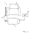
- the spool 5 shown in Fig. 2 is formed in the shape of a rod or a cylinder, and the outer periphery (seat belt contacting surface) of the spool serves as a retracting surface of the seat belt 3.
- the spool 5 is a member that retracts and withdraws the seat belt 3 for restraining the vehicle occupant depending on the driving of the motor 7 serving as a 'driving motor' of the present invention, and corresponds to a 'spool' of the present invention.
- the power transmission mechanism 9 is provided between the spool 5 and the motor 7.
- the power transmission mechanism 9 is composed of a mechanism that forms a connecting state (power transmission mode) in which the spool 5 and the motor 7 are connected to each other, and a disconnecting state (power interruption mode) in which the connecting state is released.
- the power transmission mechanism 9 is called as a 'clutch' in which gear members and like are combined.
- the connecting state of the power transmission mechanism 9 is a state in which the power of the motor 7 can be transmitted to the spool through the power transmission mechanism 9. Accordingly, when the motor 7 is driven during the connecting state, the power of the motor 7 is transmitted to the spool 5 through the power transmission mechanism 9.
- the rotational speed of the motor 7 is reduced by the power transmission mechanism 9. Meanwhile, since the mechanical connection between the spool 5 and the motor 7 is released during the disconnecting state of the power transmission mechanism 9, the seat belt 3 can be easily withdrawn from the spool 5.
- the power transmission mechanism 9 is not provided between the spool 5 and the motor 7, and it is possible to employ a structure in which the spool 5 and the motor 7 are directly connected to each other.
- the power transmission mechanism 9 is composed of a so-called 'single-stage clutch'. Accordingly, in the power transmission mode of the power transmission mechanism 9, when the motor 7 is driven so as to output a predetermined motor output, the rotational speed of the motor 7 is reduced and the rotational force thereof is transmitted to the spool 5 so that the spool 5 is driven with a predetermined rotational torque and RPM (revolution per minute). Furthermore, it is possible to use a power transmission mechanism such that the rotational torque and RPM of the spool can be varied in several stages, instead of the power transmission mechanism 9.
- the power transmission mechanism when the seat belt is retracted on the spool with a high tension, the power transmission mechanism can be set to a high speed reduction ratio mode in which the rotational torque is relatively high and the rotational speed is relatively low. Meanwhile, when the seat belt is rapidly retracted on the spool, the power transmission mechanism can be set to a low speed reduction ratio mode in which the rotational torque is relatively low and the rotational speed is relatively high.
- the following seven seat belt setting modes are set as the state of the seat belt 3, and the motor 7 and the power transmission mechanism 9 are controlled by the ECU 20 on the basis of the seat belt setting modes.
- the belt storage mode is a belt mode in which the seat belt 3 is not used and fully retracted on the spool 5.
- the motor 7 of the seat belt retractor 1 is not driven and the power transmission mechanism 9 is set in the power interruption mode. Therefore, only a very small belt tension acts on the seat belt 3, and thus the power consumption is zero.
- the belt withdrawing mode is a belt mode in which the seat belt 3 is withdrawn from the spool 5 to be fastened.
- the seat belt retractor 1 is set in the power interruption mode. Therefore, small force is enough for withdrawing the seat belt 3. In this case, the motor 7 is not driven and thus the power consumption is zero.
- the belt retracting mode for fitting is a belt mode in which an excessively withdrawn amount of the seat belt 3 is retracted to fit the seat belt 3 into a vehicle occupant after the seat belt 3 is withdrawn and the tongue (the tongue 12 in Fig. 1) is inserted into and engaged with the buckle to turn on the buckle switch (the buckle switch 16a in Fig. 1), and in which the withdrawn seat belt 3 is retracted when the vehicle occupant moves in the normal fastening state of the seat belt 3 (in this case, the buckle switch is ON) so as to withdraw the seat belt 3 in a predetermined amount and then the vehicle occupant again is seated in a regular state.
- the power transmission mechanism 9 of the seat belt retractor 1 is set in the power transmission mode, and the motor 7 thereof is controlled so as to be driven in the belt retracting direction with high rotational speed. Therefore, when the seat belt 3 is rapidly retracted on the spool 5 and then a small predetermined belt tension is generated, the motor 7 is stopped so that the seat belt 3 is fastened about the vehicle occupant.
- the normal fastening mode (comfort mode) is a belt mode, which is set after the completion of the belt retracting mode for fitting, and in which the seat belt 3 is in the normal fastening state.
- the motor 7 of the seat belt retractor 1 is not driven and the power transmission mechanism 9 is set in the power interruption mode. Therefore, since a very small tension acts on the seat belt 3, the vehicle occupant does not feel discomfort even when fastening the seat belt 3. In addition, the power consumption is zero.
- the warning mode is a belt mode in which a driver's doze or obstacles near the vehicle are detected during the drive of the vehicle in the normal fastening mode, and then the retracting operation of the seat belt 3 is repeated a predetermined number of times so as to warn the driver.
- the motor 7 of the seat belt retractor 1 is set so as to be driven repeatedly. Therefore, a relatively larger tension (smaller than the belt tension in an emergency mode to be described below) and a very small tension are alternately applied to the seat belt 3 so that the driver is warned about the doze or the obstacles around the vehicle.
- the control in the emergency mode will be described in detail below.
- the emergency mode is a belt mode to be set when the vehicle is highly in danger of colliding with obstacles during the drive of the vehicle in the normal fastening mode, or in succession to the warning mode.
- the power transmission mechanism 9 of the seat belt retractor 1 is set in the power transmission mode, and the motor 7 thereof is controlled so as to be driven in the belt retracting direction with high rotational speed and high torque. Therefore, when the seat belt 3 is rapidly retracted on the spool 5 and then a large predetermined belt tension is generated on the seat belt 3, the motor 7 is stopped so that the vehicle occupant is reliably restrained by the seat belt 3.
- the belt retracting mode for storage is a belt mode in which the seat belt 3 is fully retracted so as to be storage state when the buckle switch 16a in Fig. 1 is turned off by pulling out the tongue (the tongue 12 in Fig. 1) from the buckle in order to release the fastening of the seat belt 3.
- the power transmission mechanism 9 of the seat belt retractor 1 is set in the power transmission mode, and the motor 7 thereof is controlled so as to be driven in the belt retracting direction. Therefore, the withdrawn seat belt 3 is rapidly retracted on the spool 5. Then, when the seat belt 3 is completely retracted on the spool 5 and then a small predetermined belt tension is generated on the seat belt, the motor 7 is stopped. Accordingly, the seat belt 3 is in the belt storage mode in which a very small belt tension is generated on the seat belt.
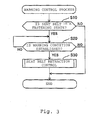
- FIG. 3 A flow chart of the warning control process in the warning mode of the seat belt retractor 1 according to the present embodiment is shown in Fig. 3.
- a step S10 in the retractor control processing.
- the buckle switch 16a shown in Fig. 1 detects that the tongue 12 is inserted into the buckle 16, it is determined that the seat belt is in the seat belt fastening state.
- the buckle switch 16a detects that the tongue 12 is disengaged from the buckle, it is determined that the seat belt is in the seat belt released state.
- step S10 when it is determined that the seat belt is the fastening state (YES in step S10), the warning control process proceeds to step S20. Meanwhile, in step S10, when it is determined that seat belt is the released state (NO in step S10), the warning control process is directly terminated.
- step S20 determines whether a warning condition is established in the step S20 shown in Fig. 3. Specifically, it is determined that the warning condition is established in cases as follows: in case of determining that the obstacles (other vehicles, obstacles, pedestrians, etc) around the vehicle are in a predetermined range, or the vehicle is highly in danger of colliding with obstacles, on the basis of the information detected by the vehicle collision information detecting sensor 32 shown in Fig. 1, or in case of determining that the driver dozes on the basis of the information detected by the sensor for detecting the variation of the tension acting on the seat belt 3.
- step S20 it is determined that the warning condition is established (YES in step S20), the warning control process proceeds to step S30 and then is terminated after the seat belt retraction control. Meanwhile, in the step S20, it is determined that the warning condition is not established (NO in step S20), and then the warning control process is directly terminated.
- the seat belt retraction control is performed by the warning mode in step S30 shown in Fig. 3.
- the motor 7 is driven so that the operations for increasing and decreasing the tension (acting for temporarily increasing the tension) acting on the seat belt 3 are repeated several times, thereby warning the vehicle occupant (driver).
- the control corresponds to a 'control for driving an electric motor so that the operations for increasing and decreasing the tension acting on the seat belt by the spool are repeated several times at the time of fastening of the seat belt about the vehicle occupant' of the present invention.
- the motor 7 is controlled so that the motion of the spool 5 becomes maximum in a seat belt retracting direction in the first operation of the operations of the seat belt retraction control repeated several times by the warning mode. Furthermore, in the present embodiment, the motor output or rotation time of the motor 7 is controlled to be relatively high in order to maximize the motion of the spool 5 in the seat belt retracting direction.
- the control corresponds to a 'control for controlling an electric motor so that a motion of the spool becomes maximum in a seat belt retracting direction in the first operation of the operations repeated several times' of the present invention, or to a 'control for relatively increasing at least one of the motor output or rotation time of the electric motor in the first operation' of the present invention.
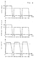
- Figs. 4 and 5 show the output and the rotational speed of the motor, and the temporal change of the belt tension in the seat belt retraction control of Fig. 3. Furthermore, all of Figs. 4 and 5 show the graphs of the results when the operations for increasing and decreasing the tension (acting for temporarily increasing the tension) acting on the seat belt 3 are repeated three times. In the present invention, it can be properly set so that the operations are repeated two times or four times or more.
- the motor is controlled in the seat belt retraction control shown in Fig. 4 so that the motor output P2 at a first operation is higher than the motor outputs P1 in second and third operations when the retracting operations of the motor 7 repeated three times are compared with one another.
- the motor output of the motor 7 is the product of the current value (called as a 'control current value') and the voltage value (called as 'an applied voltage value'). Accordingly, more specifically, the motor 7 is controlled so that the current value and the voltage value in the first operation are set larger than those in the following operations. Furthermore, in this case, the rotation times ⁇ t of the motor are set to have same values in each of the motor retracting operations.
- the tension of the seat belt 3 in the first operation is controlled to have a nearly constant value in the range exceeding the belt tension Ta.
- the tension of the seat belt may overshoot the nearly constant vale.
- the belt tension Ta of Fig. 4 is a target tension in the warning mode, and is defined as a tension causing the vehicle occupant to reliably perceive a warning.
- the motor outputs P1 and P2 and the belt tension Ta can be set on the basis of the result of the test or analysis.
- the present invention can employ a control in which the motor output in the first operation is relatively increased as compared to those in the following operations, as the control shown in Fig. 4.
- the present invention can employ a first step and a second step.
- the motor output in the first operation serving as an 'initial operation' is relatively increased as compared to the motor output at the second or third operation of the first to the third operations.
- the motor outputs in the first and the second operation serving as 'initial operations' are relatively increased as compared to the motor output at the third operation.
- the motor output at the second operation and the motor output at the third operation may be set to have a same value, or may be set to have different values from each other.
- the motor output in the first operation and the motor output at the second operation may be set to have a same value, or may be set to have different values from each other.
- the motor is controlled in the seat belt retraction control shown in Fig. 5 so that the rotation time ⁇ t1 in the first operation is longer than the rotation times ⁇ t2 in following operations when the retracting operations of the motor 7 repeated three times are compared with one another. Furthermore, in this case, the outputs and the rotational speeds of the motor are set to have same values in each of the motor retracting operations.
- the belt tension Ta of Fig. 5 is a target tension in the warning mode, and is defined as a tension causing the vehicle occupant to reliably perceive a warning.
- the rotation times ⁇ t1 and ⁇ t2 of the motor, and the belt tension Ta can be set on the basis of the result of the test or analysis.
- the present invention can employ a control in which the rotation time of the motor in the first operation is relatively increased as compared to those in the following operations, as the control shown in Fig. 5.
- the present invention can employ a third step and a fourth step.
- the rotation time of the motor in the first operation serving as an 'initial operation' is relatively increased as compared to the rotation time of the motor at the second or third operation of the first to the third operations.
- the rotation times of the motor in the first and the second operation serving as 'initial operations' are relatively increased as compared to the rotation time of the motor at the third operation.
- the rotation time of the motor at the second operation and the rotation time of the motor at the third operation may be set to have a same value, or may be set to have different values from each other.
- the rotation time of the motor in the first operation and the rotation time of the motor at the second operation may be set to have a same value, or may be set to have different values from each other.
- the seat belt retractor 1 of the present embodiment specifically, when the warning control process shown in Fig. 3 is performed as shown in Figs. 4 and 5, it is possible to quickly and reliably warn the vehicle occupant by the seat belt 3. Accordingly, it is possible to make the vehicle occupant perform the avoidance operation required due to the vehicle collision, or to warn the sleeping vehicle occupant. Furthermore, in the present embodiment, when that the vehicle is highly in danger of colliding with obstacles is determined on the basis of the information detected by the vehicle collision information detecting sensor 32, the above-mentioned emergency mode is performed in succession to the warning control process shown in Fig. 3. When a predetermined very large belt tension finally occurs on the seat belt 3, the motor 7 is stopped. Therefore, it is possible to perform a control in which the vehicle occupant is reliably restrained by the seat belt 3.
- the invention is not limited to the embodiment, and may have various applications and modifications. For example, there may be following another embodiments using the embodiment.
- any one of the motor output or the rotation time of the motor 7 in the first operation is increased in the warning control process.
- it can be configured so that both the motor output and the rotation time of the motor 7 in the first operation are increased.
- the motion of the spool can be further increased. Accordingly, when it is expected that the seat belt have a large slack in the initial operation, another embodiment is effective.
- a detecting sensor for detecting directly information about the rotation of the spool 5.
- Sensors such as a hole sensor, a variable resistor, and a photo interrupter, can be adequately used as the rotation detecting sensor. It is possible to detect detection information such as whether the spool 5 is rotated, a motion, a rotation direction, a rotational speed, and amount of rotation, by means of the rotation detecting sensor.
- the seat belt retractor 1 to be mounted in a vehicle can be used in a seat belt device mounted in the vehicle for transporting vehicle occupants, for example an automobile, an airplane, a ship, an electric train, a bus and etc.
Landscapes
- Engineering & Computer Science (AREA)
- Mechanical Engineering (AREA)
- Automotive Seat Belt Assembly (AREA)
Abstract
Description
- The present invention relates to a seat belt retractor to be mounted in a vehicle.
- In the related art, there has been known a seat belt device that has various structures for restraining a vehicle occupant by means of a seat belt of a vehicle such as an automobile.
A structure of a seat belt device, which retracts and withdraws the seat belt by driving a motor and such, is disclosed inJP-6-71333 U Patent Document 1 employs the structure, which retracts and withdraws the seat belt through a spool by a motor, as a structure of the seat belt retractor. InPatent Document 1, the tension of the seat belt is intermittently varied by driving the motor, and thus a restraining force can be varied. Accordingly, it is possible to warn a driver with respect to a vehicle collision. - However, when the warning is conducted by the seat belt device disclosed in
Patent Document 1 with respect to vehicle collision, the seat belt has an initial slack, and thus a part of the rotation of the motor is used to remove the slack at the time of an initial operation. Accordingly, it is impossible to obtain the desired belt tension that is useful to warn the vehicle occupant.
The present invention has been made to solve the above-mentioned problem, and it is an object of the present invention to provide an effective technology that is useful to reliably warn a vehicle occupant by using the seat belt of a seat belt retractor mounted in a vehicle to retract / withdraw the seat belt for restraining a vehicle occupant depending on the driving of the electric motor. - The invention is provided to achieve the above-mentioned problem. Although the invention can be typically applied to a seat belt retractor mounted in a vehicle such as an automobile, the invention can be applied to a structure of a seat belt retractor that is mounted in a vehicle other than the automobile, for example an airplane, a ship, an electric train, a bus, and so on.
- A first aspect of the invention for solving the above-mentioned problem relates to a seat belt retractor according to
claim 1.
The seat belt retractor according toclaim 1 is mounted in a vehicle, and includes at least an electric motor, a spool, and a controller. - The spool of the present invention is composed of a member that retracts and withdraws the seat belt for restraining a vehicle occupant. The seat belt to be retracted or withdrawn with the spool is a long belt to be fastened about a vehicle occupant seated in a seat, and is called as 'webbing'. Typically, the seat belt is fastened about the vehicle occupant seated in a vehicle seat during the restraint of the vehicle occupant, that is, the vehicle collision. Therefore, the vehicle occupant is restrained. Furthermore, in the present invention, if necessary, a power transmission mechanism is provided between the electric motor and the spool. The power transmission mechanism forms a connecting state in which the electric motor and the spool are connected to each other, and a disconnecting state in which the connecting state is released.
- The controller of the present invention is composed of a unit for controlling at least the electric motor, and controls a driving direction of the electric motor, a driving time, a driving force, and the like. The controller is typically composed of a CPU (central processing unit), input and output units, a memory unit, peripheral units, etc. The controller may be dedicatedly provided to the seat belt retractor, or may be used as a controller for controlling a driving system or an electrical system of a vehicle as well as the seat belt retractor.
- In the present invention, the controller controls the driving of the electric motor so that several operations for increasing and decreasing the tension acting on the seat belt by the spool are repeated so as to warn the vehicle occupant at the time of fastening of the seat belt to the vehicle occupant (typically, a driver). Specifically, warning is performed in the following cases: in the case of determining that the obstacles (other vehicles, obstacles, pedestrians, etc) around the vehicle are in a predetermined range or the vehicle is highly in danger of colliding with obstacles, or in the case of determining that the driver falls asleep. That is, the retractor of the present invention serves as a warning unit (warning system) for warning the vehicle occupant as well as a restraining unit for restraining the vehicle occupant by means of the seat belt.
- Meanwhile, when the driver is warned by means of the retracting operation of the seat belt, if the
seat belt 3 has an initial slack, a part of the rotation of the motor is typically used to remove the slack at the time of an initial operation. Accordingly, it is impossible to obtain the desired belt tension that is useful to warn the vehicle occupant.
In the present invention, the controller controls the driving of the electric motor so that a motion of the spool becomes relatively larger in a seat belt retracting direction in the initial operation of the several operations. Here, the 'initial operation' includes a first or several operations of the operations repeated several times. For example, the present invention can employ a step in which the motion of the spool in the first operation serving as an 'initial operation' is relatively increased as compared to the motion of the spool at the second or third operation of the first to the third operations, and a step in which the motions of the spool in the first and the second operation serving as 'initial operations' are relatively increased as compared to the motion of the spool at the third operation. - According to the structure of the seat belt retractor disclosed in
claim 1, the number of revolutions of the spool in the initial operation is larger than those in the following operations. Therefore, if the seat belt has an initial slack, it is possible to again generate the tension larger than a desired belt tension useful to warn the vehicle occupant after the slack is removed. In this case, even if the seat belt does not nearly have an initial slack, it goes without saying that the tension larger than the desired belt tension is obtained. Accordingly, it is possible to quickly and reliably warn the vehicle occupant by the seat belt at any one of the retracting operations of the electric motor that is repeated several times. - A second aspect of the present invention for solving the above-mentioned problem relates to a seat belt retractor according to claim 2.
In the seat belt retractor according to claim 2, the controller of the structure according toclaim 1 increases relatively at least one of the motor output or rotation time of the electric motor in the initial operation so that the motion of the spool becomes relatively larger in the seat belt retracting direction. The present invention includes a control for relatively increasing at least one of the motor output or rotation time of the electric motor in the first operation, and a control for relatively increasing both the motor output and the rotation time of the motor in the first operation. The rotational speed of the motor can be increased by increasing the motor output of the electric motor. Accordingly, for example, when the rotation times of the motor are set to have the same values in each of the motor retracting operations, the motion of the spool can become larger. Meanwhile, when the rotation time of the electric motor is increased and thus the motor outputs are set to have the same values in each of the motor retracting operations, the motion of the spool can become larger. Furthermore, in the control for increasing the motor output, each of the current value (called as a 'control current value') and the voltage value (called as an 'applied voltage value') in the initial operation is set larger than that of the following operations. - According to the structure of the seat belt retractor disclosed in claim 2, it is possible to quickly and reliably warn the vehicle occupant by means of the seat belt at any one of the retracting operations of the electric motor which is repeated several times by a control for increasing the motor output or the rotation time of the motor in the first operation.
- A third aspect of the present invention for solving the above-mentioned problem relates to a seat belt device according to
claim 3.
A seat belt device installed on a vehicle according toclaim 3, includes at least a seat belt, an electric motor, a spool, a controller, a buckle, a tongue, and a detecting sensor.
The seat belt of the present invention is a long belt to be fastened to a vehicle occupant seated in a vehicle seat, and is called as 'webbing'. Typically, the seat belt is fastened about the vehicle occupant seated in a vehicle seat during the restraint of the vehicle occupant, that is, the vehicle collision. Therefore, the vehicle occupant is restrained. Furthermore, the buckle of the present invention is composed of a member fixed to the vehicle. The tongue of the present invention is composed of a member, which is provided to the seat belt and is engaged with the buckle of the present invention at the time of fastening of the seat belt. The detecting sensor of the present invention is composed of a unit for detecting that the tongue is engaged with the buckle. In addition, the electric motor, the spool, and the controller of the present invention have the substantially same functions as components of the seat belt retractor according toclaim 1.
That is, the seat belt device of the present invention serves as a warning unit (warning system) for warning the vehicle occupant as well as a restraining unit for restraining the vehicle occupant by means of the seat belt. Furthermore, in the present invention, the controller controls the electric motor so that a motion of the spool becomes relatively larger in a seat belt retracting direction in the initial operation of the operations repeated several times. - According to the structure of the seat belt device disclosed in
claim 3, the number of revolutions of the spool in the initial operation is larger than those in the following operations. Therefore, if the seat belt has an initial slack, it is possible to again generate the tension larger than a desired belt tension useful to warn the vehicle occupant after the slack is removed. In this case, even if the seat belt does not nearly have an initial slack, it goes without saying that the tension larger than the desired belt tension is obtained. Accordingly, it is possible to quickly and reliably warn the vehicle occupant by the seat belt at any one of the retracting operations of the electric motor which is repeated several times. - A fourth aspect of the present invention for solving the above-mentioned problem relates to a seat belt device according to claim 4.
In the seat belt device according to claim 4, the controller of the structure according toclaim 3 increases relatively at least one of the motor output or rotation time of the electric motor in the initial operation so that the motion of the spool becomes relatively larger in the seat belt retracting direction.
Therefore, according to the structure of the seat belt device disclosed in claim 4, it is possible to quickly and reliably warn the vehicle occupant by means of the seat belt at any one of the retracting operations of the electric motor which is repeated several times by a control for increasing the motor output or the rotation time of the motor. - A fifth aspect of the present invention for solving the above-mentioned problem relates to a vehicle with a seat belt device according to
claim 5.
The vehicle with a seat belt device according toclaim 5 includes at least the seat belt device according toclaim 3 or 4. In the vehicle of the present invention, the seat belt device is accommodated in the accommodating space of the vehicle, for example, the accommodating space within a pillar, the accommodating space within a seat, or the accommodating space of other portions of the vehicle.
According to the structure of the vehicle with a seat belt retractor, it is possible to provide a vehicle having the seat belt device that can quickly and reliably warn the vehicle occupant by means of the seat belt at any one of the retracting operations of the electric motor repeated several times and is accommodated in the accommodating space of the vehicle. - As described above, according to the present invention, in the seat belt structure that retracts and withdraws the seat belt for restraining a vehicle occupant depending on the driving of the electric motor, particularly, in the initial operation of the operations of the spool, which are repeated several times, for increasing / decreasing the tension acting on the seat belt, the controller controls the electric motor so that a motion of the spool becomes relatively larger in a seat belt retracting direction. Accordingly, it is possible to reliably warn the vehicle occupant by means of the seat belt.
- Hereinafter, embodiments of the present invention will be described in detail with reference to drawings.
- Fig. 1 is a view showing a structure of a
seat belt device 100 according to an embodiment of the present invention; - Fig. 2 is a view showing a peripheral structure of the
seat belt retractor 1 shown in Fig. 1; - Fig. 3 is a flow chart showing a warning control process in a warning mode of the
seat belt retractor 1 according to the embodiment; - Fig. 4 is a view showing the output and the rotational speed of a motor, and the temporal change of the belt tension in the seat belt retraction control of Fig. 3 and
- Fig. 5 is a view showing the output and the rotational speed of a motor, and the temporal change of the belt tension in the seat belt retraction control of Fig. 3.
First, an embodiment of the present invention will be described with reference to Figs. 1 and 2. - As shown in Fig. 1, the
seat belt device 100 of the present embodiment is a seat belt device for a vehicle, which is mounted in a vehicle as a 'vehicle with a seat belt device', and includes aseat belt retractor 1, aseat belt 3, ashoulder guider anchor 10, atongue 12, an outer anchor 14, abuckle 16, and anECU 20, as main components. In addition, a vehicle is provided with aninput element 30. Theinput element 30 detects various information, such as information about a collision prediction or collision generation of the vehicle, a driving state of the vehicle, a seating position or a physique of a vehicle occupant seated on the seat, surrounding traffic conditions, and weather or time zones. Then, theinput element 30 inputs the detection information to theECU 20. The detection information of theinput element 30 is transmitted to theECU 20 at all times or in every predetermined time so that the detection information of theinput element 30 can be used for controlling operation of theseat belt device 100 or the like. - Specifically, the
input element 30 of the present embodiment includes a vehicle collisioninformation detecting sensor 32 for detecting information about a collision of the vehicle, such as a collision prediction or actual collision generation of the vehicle. The vehicle collisioninformation detecting sensor 32 is composed of a sensor capable of detecting detection information (detection signals) such as the distance between the vehicle and the objects (other vehicles, obstacles, pedestrians, etc) to be collided against the vehicle, relative velocity, relative acceleration, and three-directional (X-axis, Y-axis, Z-axis) acceleration acting on the vehicle. The vehicle collisioninformation detecting sensor 32 may be composed of single detecting sensor, or may be constituted by combining the single detecting sensors to one another. Specifically, the vehicle collisioninformation detecting sensor 32 can be constituted by using a millimeter-wave radar, a laser radar, an acceleration sensor, a camera sensor, or the like. - The
seat belt 3 is a long belt (webbing) that is used to restrain or release a vehicle occupant C (called as a 'driver') seated in avehicle seat 40, that is, a driver's seat. Theseat belt 3 corresponds to a 'seat belt for restraining a vehicle occupant' of the present invention. Theseat belt 3 is withdrawn from aseat belt retractor 1 fixed to the vehicle, and is connected to an outer anchor 14 by atongue 12 via ashoulder guide anchor 10 provided in the portion corresponding to the shoulder of the vehicle occupant C. Theshoulder guide anchor 10 functions to lock and guides theseat belt 3 in the portion corresponding to the shoulder of the vehicle occupant C. Theseat belt 3 is fastened about the vehicle occupant C by inserting (engaging) thetongue 12 into abuckle 16 fixed to the vehicle body. Thetongue 12 corresponds to a 'tongue' of the present invention, and thebuckle 16 with which thetongue 12 is engaged corresponds to a 'buckle' of the present invention. - Furthermore, the
buckle 16 is provided with abuckle switch 16a, and thebuckle switch 16a detects that the seat belt buckle (fastening of the seat belt) is operated by inserting thetongue 12 into thebuckle 16. The information detected by thebuckle switch 16a is transmitted to theECU 20, and thus determines whether the seat belt is fastened or not. Thebuckle switch 16a corresponds to a 'detecting sensor for detecting that the tongue is engaged with the buckle' of the present invention. - The
seat belt retractor 1 is a unit capable of retracting and withdrawing theseat belt 3 by means of aspool 5 and a motor 7 to be described below, and corresponds to a 'seat belt retractor' of the present invention. As shown in Fig. 1, theseat belt retractor 1 is mounted in the accommodating space, which is formed in aB pillar 42 of the vehicle. - The
ECU 20 has a function that causes theseat belt retractor 1 to start on the basis of signals from theinput element 30 and various operating mechanisms to be controlled, and is composed of a CPU (central processing unit), input and output units, a memory unit, peripheral units, etc. In the description of the present embodiment, in particular, theECU 20 controls a motor 7, to be described below, of theseat belt retractor 1. Specifically, theECU 20 controls a supply amount or a supply direction of the current supplied to an electromagnetic coil of the motor 7. Accordingly, the rotational speed, the rotation direction, the rotation time, and the rotational torque (output) of a motor shaft are varied. As described in detail below, theECU 20 is composed of a unit for controlling the driving of the motor 7 and is composed of a unit for switching a state, in which a driving force of the motor 7 is transmitted to thespool 5, by controlling a power transmission mechanism 9 to be described below. In addition, theECU 20 has a function to detect (measure) the current value of the motor during the operation of the motor 7. TheECU 20 corresponds to a 'controller'.
Moreover, theECU 20 may be provided to theseat belt retractor 1 as a dedicated controller, or may be used as a controller for controlling a driving system or an electrical system of the vehicle as well as theseat belt retractor 1. - The
spool 5 shown in Fig. 2 is formed in the shape of a rod or a cylinder, and the outer periphery (seat belt contacting surface) of the spool serves as a retracting surface of theseat belt 3. Thespool 5 is a member that retracts and withdraws theseat belt 3 for restraining the vehicle occupant depending on the driving of the motor 7 serving as a 'driving motor' of the present invention, and corresponds to a 'spool' of the present invention. - Furthermore, in the present embodiment, the power transmission mechanism 9 is provided between the
spool 5 and the motor 7. The power transmission mechanism 9 is composed of a mechanism that forms a connecting state (power transmission mode) in which thespool 5 and the motor 7 are connected to each other, and a disconnecting state (power interruption mode) in which the connecting state is released. The power transmission mechanism 9 is called as a 'clutch'
in which gear members and like are combined. The connecting state of the power transmission mechanism 9 is a state in which the power of the motor 7 can be transmitted to the spool through the power transmission mechanism 9. Accordingly, when the motor 7 is driven during the connecting state, the power of the motor 7 is transmitted to thespool 5 through the power transmission mechanism 9. In this case, the rotational speed of the motor 7 is reduced by the power transmission mechanism 9. Meanwhile, since the mechanical connection between thespool 5 and the motor 7 is released during the disconnecting state of the power transmission mechanism 9, theseat belt 3 can be easily withdrawn from thespool 5. In addition, if necessary, the power transmission mechanism 9 is not provided between thespool 5 and the motor 7, and it is possible to employ a structure in which thespool 5 and the motor 7 are directly connected to each other. - Although not specifically shown in the present embodiment, the power transmission mechanism 9 is composed of a so-called 'single-stage clutch'. Accordingly, in the power transmission mode of the power transmission mechanism 9, when the motor 7 is driven so as to output a predetermined motor output, the rotational speed of the motor 7 is reduced and the rotational force thereof is transmitted to the
spool 5 so that thespool 5 is driven with a predetermined rotational torque and RPM (revolution per minute).
Furthermore, it is possible to use a power transmission mechanism such that the rotational torque and RPM of the spool can be varied in several stages, instead of the power transmission mechanism 9. For example, in a case in which a two-stage clutch for varying the rotational torque and RPM of the spool during two stages is used as the power transmission mechanism, when the seat belt is retracted on the spool with a high tension, the power transmission mechanism can be set to a high speed reduction ratio mode in which the rotational torque is relatively high and the rotational speed is relatively low. Meanwhile, when the seat belt is rapidly retracted on the spool, the power transmission mechanism can be set to a low speed reduction ratio mode in which the rotational torque is relatively low and the rotational speed is relatively high. - In the present embodiment, the following seven seat belt setting modes are set as the state of the
seat belt 3, and the motor 7 and the power transmission mechanism 9 are controlled by theECU 20 on the basis of the seat belt setting modes. - The belt storage mode is a belt mode in which the
seat belt 3 is not used and fully retracted on thespool 5. In the belt storage mode, the motor 7 of theseat belt retractor 1 is not driven and the power transmission mechanism 9 is set in the power interruption mode. Therefore, only a very small belt tension acts on theseat belt 3, and thus the power consumption is zero. - The belt withdrawing mode is a belt mode in which the
seat belt 3 is withdrawn from thespool 5 to be fastened. In the same way, in the belt withdrawing mode, theseat belt retractor 1 is set in the power interruption mode. Therefore, small force is enough for withdrawing theseat belt 3. In this case, the motor 7 is not driven and thus the power consumption is zero. - The belt retracting mode for fitting is a belt mode in which an excessively withdrawn amount of the
seat belt 3 is retracted to fit theseat belt 3 into a vehicle occupant after theseat belt 3 is withdrawn and the tongue (thetongue 12 in Fig. 1) is inserted into and engaged with the buckle to turn on the buckle switch (thebuckle switch 16a in Fig. 1), and in which the withdrawnseat belt 3 is retracted when the vehicle occupant moves in the normal fastening state of the seat belt 3 (in this case, the buckle switch is ON) so as to withdraw theseat belt 3 in a predetermined amount and then the vehicle occupant again is seated in a regular state. In the belt retracting mode for fitting, the power transmission mechanism 9 of theseat belt retractor 1 is set in the power transmission mode, and the motor 7 thereof is controlled so as to be driven in the belt retracting direction with high rotational speed. Therefore, when theseat belt 3 is rapidly retracted on thespool 5 and then a small predetermined belt tension is generated, the motor 7 is stopped so that theseat belt 3 is fastened about the vehicle occupant. - The normal fastening mode (comfort mode) is a belt mode, which is set after the completion of the belt retracting mode for fitting, and in which the
seat belt 3 is in the normal fastening state. In the normal fastening mode, the motor 7 of theseat belt retractor 1 is not driven and the power transmission mechanism 9 is set in the power interruption mode. Therefore, since a very small tension acts on theseat belt 3, the vehicle occupant does not feel discomfort even when fastening theseat belt 3. In addition, the power consumption is zero. - The warning mode is a belt mode in which a driver's doze or obstacles near the vehicle are detected during the drive of the vehicle in the normal fastening mode, and then the retracting operation of the
seat belt 3 is repeated a predetermined number of times so as to warn the driver. In the warning mode, the motor 7 of theseat belt retractor 1 is set so as to be driven repeatedly. Therefore, a relatively larger tension (smaller than the belt tension in an emergency mode to be described below) and a very small tension are alternately applied to theseat belt 3 so that the driver is warned about the doze or the obstacles around the vehicle. The control in the emergency mode will be described in detail below. - The emergency mode is a belt mode to be set when the vehicle is highly in danger of colliding with obstacles during the drive of the vehicle in the normal fastening mode, or in succession to the warning mode. In the emergency mode, the power transmission mechanism 9 of the
seat belt retractor 1 is set in the power transmission mode, and the motor 7 thereof is controlled so as to be driven in the belt retracting direction with high rotational speed and high torque. Therefore, when theseat belt 3 is rapidly retracted on thespool 5 and then a large predetermined belt tension is generated on theseat belt 3, the motor 7 is stopped so that the vehicle occupant is reliably restrained by theseat belt 3. - The belt retracting mode for storage is a belt mode in which the
seat belt 3 is fully retracted so as to be storage state when thebuckle switch 16a in Fig. 1 is turned off by pulling out the tongue (thetongue 12 in Fig. 1) from the buckle in order to release the fastening of theseat belt 3. In the belt retracting mode for storage, the power transmission mechanism 9 of theseat belt retractor 1 is set in the power transmission mode, and the motor 7 thereof is controlled so as to be driven in the belt retracting direction. Therefore, the withdrawnseat belt 3 is rapidly retracted on thespool 5. Then, when theseat belt 3 is completely retracted on thespool 5 and then a small predetermined belt tension is generated on the seat belt, the motor 7 is stopped. Accordingly, theseat belt 3 is in the belt storage mode in which a very small belt tension is generated on the seat belt. - Hereinafter, the control of the above-mentioned
seat belt retractor 1 in the warning mode will be described in detail with reference to Figs. 3 to 5. The control of theseat belt retractor 1 is performed by theECU 20 shown in Figs. 1 and 2. - A flow chart of the warning control process in the warning mode of the
seat belt retractor 1 according to the present embodiment is shown in Fig. 3.
As shown in Fig. 3, first, whether the seat belt is in the seat belt fastening state is determined by a step S10 in the retractor control processing. Specifically, when thebuckle switch 16a shown in Fig. 1 detects that thetongue 12 is inserted into thebuckle 16, it is determined that the seat belt is in the seat belt fastening state. When thebuckle switch 16a detects that thetongue 12 is disengaged from the buckle, it is determined that the seat belt is in the seat belt released state.
In step S10, when it is determined that the seat belt is the fastening state (YES in step S10), the warning control process proceeds to step S20. Meanwhile, in step S10, when it is determined that seat belt is the released state (NO in step S10), the warning control process is directly terminated. - Next, whether a warning condition is established is determined in the step S20 shown in Fig. 3. Specifically, it is determined that the warning condition is established in cases as follows: in case of determining that the obstacles (other vehicles, obstacles, pedestrians, etc) around the vehicle are in a predetermined range, or the vehicle is highly in danger of colliding with obstacles, on the basis of the information detected by the vehicle collision
information detecting sensor 32 shown in Fig. 1, or in case of determining that the driver dozes on the basis of the information detected by the sensor for detecting the variation of the tension acting on theseat belt 3.
In step S20, it is determined that the warning condition is established (YES in step S20), the warning control process proceeds to step S30 and then is terminated after the seat belt retraction control. Meanwhile, in the step S20, it is determined that the warning condition is not established (NO in step S20), and then the warning control process is directly terminated. - Next, the seat belt retraction control is performed by the warning mode in step S30 shown in Fig. 3. In the seat belt retraction control, the motor 7 is driven so that the operations for increasing and decreasing the tension (acting for temporarily increasing the tension) acting on the
seat belt 3 are repeated several times, thereby warning the vehicle occupant (driver). The control corresponds to a 'control for driving an electric motor so that the operations for increasing and decreasing the tension acting on the seat belt by the spool are repeated several times at the time of fastening of the seat belt about the vehicle occupant' of the present invention. - However, when the vehicle occupant is warned through the operations for retracting the
seat belt 3, if theseat belt 3 has an initial slack, a part of the rotation of the motor is used to remove the slack at the time of an initial operation, typically, in the first operation. Accordingly, it is impossible to obtain the belt tension which is useful to warn the vehicle occupant.
Here, in the present embodiment, the motor 7 is controlled so that the motion of thespool 5 becomes maximum in a seat belt retracting direction in the first operation of the operations of the seat belt retraction control repeated several times by the warning mode. Furthermore, in the present embodiment, the motor output or rotation time of the motor 7 is controlled to be relatively high in order to maximize the motion of thespool 5 in the seat belt retracting direction. The control corresponds to a 'control for controlling an electric motor so that a motion of the spool becomes maximum in a seat belt retracting direction in the first operation of the operations repeated several times' of the present invention, or to a 'control for relatively increasing at least one of the motor output or rotation time of the electric motor in the first operation' of the present invention. - Here, Figs. 4 and 5 show the output and the rotational speed of the motor, and the temporal change of the belt tension in the seat belt retraction control of Fig. 3. Furthermore, all of Figs. 4 and 5 show the graphs of the results when the operations for increasing and decreasing the tension (acting for temporarily increasing the tension) acting on the
seat belt 3 are repeated three times. In the present invention, it can be properly set so that the operations are repeated two times or four times or more. - The motor is controlled in the seat belt retraction control shown in Fig. 4 so that the motor output P2 at a first operation is higher than the motor outputs P1 in second and third operations when the retracting operations of the motor 7 repeated three times are compared with one another. The motor output of the motor 7 is the product of the current value (called as a 'control current value') and the voltage value (called as 'an applied voltage value'). Accordingly, more specifically, the motor 7 is controlled so that the current value and the voltage value in the first operation are set larger than those in the following operations. Furthermore, in this case, the rotation times Δt of the motor are set to have same values in each of the motor retracting operations.
- For this reason, since the rotational speed V2 of the motor in the first operation is higher than the rotational speeds V1 of the motor in the following operations, the number of revolutions of the
spool 5 is large in the first operation. Therefore, if theseat belt 3 has an initial slack, it is possible to generate the tension larger than a desired belt tension Ta useful to warn the vehicle occupant after the slack is removed. In this case, even if theseat belt 3 does not nearly have an initial slack, it goes without saying that the tension larger than the belt tension Ta is obtained. Accordingly, it is possible to quickly and reliably warn the vehicle occupant by theseat belt 3 at any one of the retracting operations of the motor 7 repeated three times. Furthermore, in Fig. 4, the tension of theseat belt 3 in the first operation is controlled to have a nearly constant value in the range exceeding the belt tension Ta. However, the tension of the seat belt may overshoot the nearly constant vale.
Here, the belt tension Ta of Fig. 4 is a target tension in the warning mode, and is defined as a tension causing the vehicle occupant to reliably perceive a warning. Typically, when the seat belt has a slack, at least the relationship between the motor output and the belt tension is obtained by the test or analysis that is performed in advance. Then, the motor outputs P1 and P2, and the belt tension Ta can be set on the basis of the result of the test or analysis. - Moreover, the present invention can employ a control in which the motor output in the first operation is relatively increased as compared to those in the following operations, as the control shown in Fig. 4. Specifically, the present invention can employ a first step and a second step. In the first step, the motor output in the first operation serving as an 'initial operation' is relatively increased as compared to the motor output at the second or third operation of the first to the third operations. In the second step, the motor outputs in the first and the second operation serving as 'initial operations' are relatively increased as compared to the motor output at the third operation. In the first step, the motor output at the second operation and the motor output at the third operation may be set to have a same value, or may be set to have different values from each other. In the same way, in the second step, the motor output in the first operation and the motor output at the second operation may be set to have a same value, or may be set to have different values from each other.
- The motor is controlled in the seat belt retraction control shown in Fig. 5 so that the rotation time Δt1 in the first operation is longer than the rotation times Δt2 in following operations when the retracting operations of the motor 7 repeated three times are compared with one another. Furthermore, in this case, the outputs and the rotational speeds of the motor are set to have same values in each of the motor retracting operations.
- For this reason, the number of revolutions of the
spool 5 is large in the first operation. Therefore, if theseat belt 3 has an initial slack, it is possible to generate the tension larger than a desired belt tension Ta useful to warn the vehicle occupant after the slack is removed. In this case, even if theseat belt 3 does not nearly have an initial slack, it goes without saying that the tension larger than the belt tension Ta is obtained. Accordingly, it is possible to quickly and reliably warn the vehicle occupant by theseat belt 3 at any one of the retracting operations of the motor 7 repeated three times. Here, the belt tension Ta of Fig. 5 is a target tension in the warning mode, and is defined as a tension causing the vehicle occupant to reliably perceive a warning. Typically, when the seat belt has a slack, at least the relationship between the motor output and the belt tension is obtained by the test or analysis that is performed in advance. Then, the rotation times Δt1 and Δt2 of the motor, and the belt tension Ta can be set on the basis of the result of the test or analysis. - Moreover, the present invention can employ a control in which the rotation time of the motor in the first operation is relatively increased as compared to those in the following operations, as the control shown in Fig. 5. Specifically, the present invention can employ a third step and a fourth step. In the third step, the rotation time of the motor in the first operation serving as an 'initial operation' is relatively increased as compared to the rotation time of the motor at the second or third operation of the first to the third operations. In the fourth step, the rotation times of the motor in the first and the second operation serving as 'initial operations' are relatively increased as compared to the rotation time of the motor at the third operation. In the third step, the rotation time of the motor at the second operation and the rotation time of the motor at the third operation may be set to have a same value, or may be set to have different values from each other. In the same way, in the fourth step, the rotation time of the motor in the first operation and the rotation time of the motor at the second operation may be set to have a same value, or may be set to have different values from each other.
- According to the
seat belt retractor 1 of the present embodiment, specifically, when the warning control process shown in Fig. 3 is performed as shown in Figs. 4 and 5, it is possible to quickly and reliably warn the vehicle occupant by theseat belt 3. Accordingly, it is possible to make the vehicle occupant perform the avoidance operation required due to the vehicle collision, or to warn the sleeping vehicle occupant.
Furthermore, in the present embodiment, when that the vehicle is highly in danger of colliding with obstacles is determined on the basis of the information detected by the vehicle collisioninformation detecting sensor 32, the above-mentioned emergency mode is performed in succession to the warning control process shown in Fig. 3. When a predetermined very large belt tension finally occurs on theseat belt 3, the motor 7 is stopped. Therefore, it is possible to perform a control in which the vehicle occupant is reliably restrained by theseat belt 3. - Furthermore, the invention is not limited to the embodiment, and may have various applications and modifications. For example, there may be following another embodiments using the embodiment.
- In the above-mentioned embodiment, it is disclosed that any one of the motor output or the rotation time of the motor 7 in the first operation is increased in the warning control process. However, in another embodiment, it can be configured so that both the motor output and the rotation time of the motor 7 in the first operation are increased.
In another embodiment, the motion of the spool can be further increased. Accordingly, when it is expected that the seat belt have a large slack in the initial operation, another embodiment is effective. - Moreover, in the above-mentioned embodiment, if necessary, it is possible to provide a detecting sensor for detecting directly information about the rotation of the
spool 5. Sensors, such as a hole sensor, a variable resistor, and a photo interrupter, can be adequately used as the rotation detecting sensor. It is possible to detect detection information such as whether thespool 5 is rotated, a motion, a rotation direction, a rotational speed, and amount of rotation, by means of the rotation detecting sensor. - Moreover, although structure of the
seat belt retractor 1 to be mounted in a vehicle is disclosed in the above-mentioned embodiment, the seat belt retractor according to the present invention can be used in a seat belt device mounted in the vehicle for transporting vehicle occupants, for example an automobile, an airplane, a ship, an electric train, a bus and etc.
Claims (5)
- A seat belt retractor to be mounted in a vehicle comprising:an electric motor;a spool that retracts and withdraws a seat belt for restraining a vehicle occupant depending on driving of the electric motor; anda controller that controls the driving of the electric motor,wherein the controller controls the driving of the electric motor so that several operations for increasing and decreasing the tension acting on the seat belt by the spool are repeated so as to warn the vehicle occupant at the time of fastening the seat belt to the vehicle occupant, andthe controller controls the driving of the electric motor so that the motion of the spool becomes relatively larger in a seat belt retracting direction in the initial operation of the several operations.
- The seat belt retractor according to Claim 1, wherein the controller controls at least one of the motor output or rotation time of the electric motor so as to relatively increase in the initial operation so that the motion of the spool becomes relatively larger in the seat belt retracting direction.
- A seat belt device to be mounted in a vehicle comprising:a seat belt for restraining a vehicle occupant that is fastened to a vehicle occupant;an electric motor;a spool that retracts and withdraws the seat belt depending on driving of the electric motor;a controller that controls the driving of the electric motor,a buckle that is fixed to the vehicle;a tongue that is provided to the seat belt so as to engage with the buckle at the time of fastening the seat belt; anda detecting sensor for detecting whether the tongue is engaged with the buckle,wherein when it is determined that the seat belt is fastened to the vehicle occupant on the basis of the detection information detected by the detecting sensor, the controller controls the driving of the electric motor so that the several operations for increasing and decreasing the tension acting on the seat belt by the spool are repeated so as to warn the vehicle occupant, andthe controller controls the driving of the electric motor so that the motion of the spool becomes relatively larger in a seat belt retracting direction in the initial operation of the several operations.
- The seat belt device according to Claim 3, wherein the controller controls at least one of the motor output or rotation time of the electric motor so as to relatively increase in the initial operation so that the motion of the spool becomes relatively larger in the seat belt retracting direction.
- A vehicle with a seat belt device that the seat belt device according to Claim 3 or 4 is accommodated in an accommodating space of the vehicle.
Applications Claiming Priority (1)
| Application Number | Priority Date | Filing Date | Title |
|---|---|---|---|
| JP2005208986A JP4644549B2 (en) | 2005-07-19 | 2005-07-19 | Seat belt retractor, seat belt device, vehicle with seat belt device |
Publications (2)
| Publication Number | Publication Date |
|---|---|
| EP1745994A1 true EP1745994A1 (en) | 2007-01-24 |
| EP1745994B1 EP1745994B1 (en) | 2008-06-11 |
Family
ID=37114352
Family Applications (1)
| Application Number | Title | Priority Date | Filing Date |
|---|---|---|---|
| EP06012677A Not-in-force EP1745994B1 (en) | 2005-07-19 | 2006-06-20 | Seat belt retractor, seat belt device, and vehicle with seat belt device |
Country Status (5)
| Country | Link |
|---|---|
| US (1) | US7600600B2 (en) |
| EP (1) | EP1745994B1 (en) |
| JP (1) | JP4644549B2 (en) |
| CN (1) | CN1899894B (en) |
| DE (1) | DE602006001440D1 (en) |
Cited By (1)
| Publication number | Priority date | Publication date | Assignee | Title |
|---|---|---|---|---|
| DE102021100579A1 (en) | 2021-01-13 | 2022-07-14 | Bayerische Motoren Werke Aktiengesellschaft | providing a warning to a driver of a vehicle |
Families Citing this family (16)
| Publication number | Priority date | Publication date | Assignee | Title |
|---|---|---|---|---|
| JP3926748B2 (en) * | 2003-01-24 | 2007-06-06 | 本田技研工業株式会社 | Seat belt device |
| JP4644549B2 (en) * | 2005-07-19 | 2011-03-02 | タカタ株式会社 | Seat belt retractor, seat belt device, vehicle with seat belt device |
| JP2007131113A (en) * | 2005-11-09 | 2007-05-31 | Honda Motor Co Ltd | Vehicle seat belt device |
| JP4729111B2 (en) * | 2009-02-13 | 2011-07-20 | 本田技研工業株式会社 | Vehicle seat belt device |
| US20110251803A1 (en) * | 2010-04-09 | 2011-10-13 | Lucas Teurlay | Assembly, system, and method for cable tension measurement |
| JP5765138B2 (en) * | 2011-08-25 | 2015-08-19 | タカタ株式会社 | Restraint device |
| EP3018010B1 (en) * | 2014-11-06 | 2018-01-10 | Volvo Car Corporation | Method for controlling a time of activation of a reversible restraint system in a vehicle |
| US10604259B2 (en) | 2016-01-20 | 2020-03-31 | Amsafe, Inc. | Occupant restraint systems having extending restraints, and associated systems and methods |
| JP6895731B2 (en) * | 2016-10-11 | 2021-06-30 | 株式会社東海理化電機製作所 | Driver state estimator |
| JP6748390B2 (en) * | 2017-03-29 | 2020-09-02 | 株式会社東海理化電機製作所 | Seat belt device |
| KR102626248B1 (en) * | 2017-12-11 | 2024-01-17 | 현대자동차주식회사 | An Active seat belt control apparatus and control method thereof |
| JP6984557B2 (en) | 2018-07-18 | 2021-12-22 | トヨタ自動車株式会社 | Seat belt controller |
| CN112660064B (en) * | 2020-12-30 | 2022-12-02 | 大众问问(北京)信息科技有限公司 | Seat belt control method, device, computer device and storage medium in vehicle |
| JP7229283B2 (en) * | 2021-02-04 | 2023-02-27 | 本田技研工業株式会社 | vehicle seat belt device |
| JP7700769B2 (en) * | 2022-10-14 | 2025-07-01 | トヨタ自動車株式会社 | Surveillance system, surveillance computer program, and surveillance method |
| US12528440B2 (en) * | 2023-10-30 | 2026-01-20 | GM Global Technology Operations LLC | Seatbelt system |
Citations (5)
| Publication number | Priority date | Publication date | Assignee | Title |
|---|---|---|---|---|
| JPH0671333U (en) | 1993-03-22 | 1994-10-07 | 日産ディーゼル工業株式会社 | Vehicle collision warning device |
| DE19636448A1 (en) * | 1995-09-08 | 1997-04-10 | Takata Corp | Vehicle occupant restraint system |
| EP1498326A1 (en) * | 2003-07-14 | 2005-01-19 | Takata Corporation | Seat belt retractor |
| EP1707455A2 (en) * | 2005-03-31 | 2006-10-04 | Takata Corporation | Seatbelt retractor, seatbelt apparatus, and motor vehicle having a seatbelt apparatus |
| EP1712435A2 (en) * | 2005-04-14 | 2006-10-18 | Takata Corporation | Seat belt retractor, seat belt device, and vehicle with seat belt device |
Family Cites Families (15)
| Publication number | Priority date | Publication date | Assignee | Title |
|---|---|---|---|---|
| JP2856297B2 (en) | 1992-08-28 | 1999-02-10 | 宇部興産株式会社 | Method and apparatus for cooling extruded material |
| US6485057B1 (en) * | 1997-12-16 | 2002-11-26 | Nsk Autoliv Co., Ltd. | Automotive passenger restraint and protection apparatus and seatbelt protraction and retraction amount-detecting device |
| JP4467688B2 (en) * | 1999-01-19 | 2010-05-26 | タカタ株式会社 | Seat belt retractor |
| US7128343B2 (en) * | 2001-02-06 | 2006-10-31 | Autoliv Asp,Inc. | Safety-belt arrangement |
| JP4290574B2 (en) * | 2003-01-24 | 2009-07-08 | 本田技研工業株式会社 | Vehicle travel safety device |
| JP4290573B2 (en) * | 2003-01-24 | 2009-07-08 | 本田技研工業株式会社 | Vehicle travel safety device |
| US6935590B2 (en) * | 2003-05-19 | 2005-08-30 | Autoliv Asp, Inc. | Sensor for a feedback control system |
| JP4023411B2 (en) * | 2003-07-18 | 2007-12-19 | 日産自動車株式会社 | Vehicle seat belt device |
| JP2006103453A (en) * | 2004-10-04 | 2006-04-20 | Takata Corp | Seat belt retractor and seat belt device using the same |
| JP4674714B2 (en) * | 2004-12-01 | 2011-04-20 | タカタ株式会社 | Seat belt retractor, seat belt device, vehicle with seat belt device |
| JP4671674B2 (en) * | 2004-12-01 | 2011-04-20 | タカタ株式会社 | Seat belt retractor, seat belt device, vehicle with seat belt device |
| JP2006159969A (en) * | 2004-12-02 | 2006-06-22 | Tkj Kk | Seat belt retractor, seat belt device and vehicle with seat belt device |
| JP2006290285A (en) * | 2005-04-14 | 2006-10-26 | Takata Corp | Seat belt retractor, seat belt device, and vehicle having the seat belt device |
| JP4644549B2 (en) * | 2005-07-19 | 2011-03-02 | タカタ株式会社 | Seat belt retractor, seat belt device, vehicle with seat belt device |
| JP4773766B2 (en) * | 2005-08-05 | 2011-09-14 | タカタ株式会社 | Seat belt retractor, seat belt device, vehicle with seat belt device |
-
2005
- 2005-07-19 JP JP2005208986A patent/JP4644549B2/en not_active Expired - Fee Related
-
2006
- 2006-06-20 DE DE602006001440T patent/DE602006001440D1/en active Active
- 2006-06-20 EP EP06012677A patent/EP1745994B1/en not_active Not-in-force
- 2006-07-11 US US11/483,554 patent/US7600600B2/en not_active Expired - Fee Related
- 2006-07-19 CN CN2006101061489A patent/CN1899894B/en not_active Expired - Fee Related
Patent Citations (5)
| Publication number | Priority date | Publication date | Assignee | Title |
|---|---|---|---|---|
| JPH0671333U (en) | 1993-03-22 | 1994-10-07 | 日産ディーゼル工業株式会社 | Vehicle collision warning device |
| DE19636448A1 (en) * | 1995-09-08 | 1997-04-10 | Takata Corp | Vehicle occupant restraint system |
| EP1498326A1 (en) * | 2003-07-14 | 2005-01-19 | Takata Corporation | Seat belt retractor |
| EP1707455A2 (en) * | 2005-03-31 | 2006-10-04 | Takata Corporation | Seatbelt retractor, seatbelt apparatus, and motor vehicle having a seatbelt apparatus |
| EP1712435A2 (en) * | 2005-04-14 | 2006-10-18 | Takata Corporation | Seat belt retractor, seat belt device, and vehicle with seat belt device |
Cited By (1)
| Publication number | Priority date | Publication date | Assignee | Title |
|---|---|---|---|---|
| DE102021100579A1 (en) | 2021-01-13 | 2022-07-14 | Bayerische Motoren Werke Aktiengesellschaft | providing a warning to a driver of a vehicle |
Also Published As
| Publication number | Publication date |
|---|---|
| EP1745994B1 (en) | 2008-06-11 |
| JP4644549B2 (en) | 2011-03-02 |
| US7600600B2 (en) | 2009-10-13 |
| JP2007022400A (en) | 2007-02-01 |
| CN1899894A (en) | 2007-01-24 |
| CN1899894B (en) | 2010-05-12 |
| DE602006001440D1 (en) | 2008-07-24 |
| US20070018445A1 (en) | 2007-01-25 |
Similar Documents
| Publication | Publication Date | Title |
|---|---|---|
| EP1745994B1 (en) | Seat belt retractor, seat belt device, and vehicle with seat belt device | |
| EP1726494A2 (en) | Seat belt retractor, seat belt apparatus, and vehicle with a seat belt apparatus | |
| EP1790540A1 (en) | Seat belt retractor, seat belt apparatus, and vehicle with seat belt apparatus | |
| US7946375B2 (en) | Seat belt retractor and seat belt apparatus | |
| EP1738978A1 (en) | Seat belt retractor, seat belt apparatus, and vehicle with a seat belt apparatus | |
| JP2011230691A (en) | Control device of seat belt retractor, and seat belt device including the same | |
| JP4714525B2 (en) | Seat belt retractor, seat belt device, vehicle with seat belt device | |
| EP1759938B1 (en) | Seat belt apparatus and vehicle | |
| JP4773766B2 (en) | Seat belt retractor, seat belt device, vehicle with seat belt device | |
| EP1777127B1 (en) | Seat belt retractor, seat belt apparatus, and vehicle with seat belt apparatus | |
| US11364873B2 (en) | Control device for vehicle seat belt | |
| CN111038437B (en) | Seat belt device for vehicle and control method of seat belt device | |
| US11590928B2 (en) | Control device for seat belt of vehicle | |
| JP2004322694A (en) | Vehicle seat belt device | |
| JP2011230690A (en) | Control device of seat belt retractor, and seat belt device including the same | |
| JP2004322689A (en) | Vehicle seat belt device |
Legal Events
| Date | Code | Title | Description |
|---|---|---|---|
| PUAI | Public reference made under article 153(3) epc to a published international application that has entered the european phase |
Free format text: ORIGINAL CODE: 0009012 |
|
| AK | Designated contracting states |
Kind code of ref document: A1 Designated state(s): AT BE BG CH CY CZ DE DK EE ES FI FR GB GR HU IE IS IT LI LT LU LV MC NL PL PT RO SE SI SK TR |
|
| AX | Request for extension of the european patent |
Extension state: AL BA HR MK YU |
|
| 17P | Request for examination filed |
Effective date: 20070709 |
|
| 17Q | First examination report despatched |
Effective date: 20070809 |
|
| AKX | Designation fees paid |
Designated state(s): DE FR GB SE |
|
| GRAP | Despatch of communication of intention to grant a patent |
Free format text: ORIGINAL CODE: EPIDOSNIGR1 |
|
| GRAS | Grant fee paid |
Free format text: ORIGINAL CODE: EPIDOSNIGR3 |
|
| GRAA | (expected) grant |
Free format text: ORIGINAL CODE: 0009210 |
|
| AK | Designated contracting states |
Kind code of ref document: B1 Designated state(s): DE FR GB SE |
|
| REG | Reference to a national code |
Ref country code: GB Ref legal event code: FG4D |
|
| REF | Corresponds to: |
Ref document number: 602006001440 Country of ref document: DE Date of ref document: 20080724 Kind code of ref document: P |
|
| PG25 | Lapsed in a contracting state [announced via postgrant information from national office to epo] |
Ref country code: SE Free format text: LAPSE BECAUSE OF FAILURE TO SUBMIT A TRANSLATION OF THE DESCRIPTION OR TO PAY THE FEE WITHIN THE PRESCRIBED TIME-LIMIT Effective date: 20080911 |
|
| PLBE | No opposition filed within time limit |
Free format text: ORIGINAL CODE: 0009261 |
|
| STAA | Information on the status of an ep patent application or granted ep patent |
Free format text: STATUS: NO OPPOSITION FILED WITHIN TIME LIMIT |
|
| 26N | No opposition filed |
Effective date: 20090312 |
|
| REG | Reference to a national code |
Ref country code: FR Ref legal event code: ST Effective date: 20100730 |
|
| PG25 | Lapsed in a contracting state [announced via postgrant information from national office to epo] |
Ref country code: FR Free format text: LAPSE BECAUSE OF NON-PAYMENT OF DUE FEES Effective date: 20080811 |
|
| PGFP | Annual fee paid to national office [announced via postgrant information from national office to epo] |
Ref country code: DE Payment date: 20130612 Year of fee payment: 8 Ref country code: GB Payment date: 20130619 Year of fee payment: 8 |
|
| REG | Reference to a national code |
Ref country code: DE Ref legal event code: R119 Ref document number: 602006001440 Country of ref document: DE |
|
| GBPC | Gb: european patent ceased through non-payment of renewal fee |
Effective date: 20140620 |
|
| REG | Reference to a national code |
Ref country code: DE Ref legal event code: R119 Ref document number: 602006001440 Country of ref document: DE Effective date: 20150101 |
|
| PG25 | Lapsed in a contracting state [announced via postgrant information from national office to epo] |
Ref country code: DE Free format text: LAPSE BECAUSE OF NON-PAYMENT OF DUE FEES Effective date: 20150101 |
|
| PG25 | Lapsed in a contracting state [announced via postgrant information from national office to epo] |
Ref country code: GB Free format text: LAPSE BECAUSE OF NON-PAYMENT OF DUE FEES Effective date: 20140620 |