EP1745973A1 - Driving system for a working vehicle - Google Patents
Driving system for a working vehicle Download PDFInfo
- Publication number
- EP1745973A1 EP1745973A1 EP06122900A EP06122900A EP1745973A1 EP 1745973 A1 EP1745973 A1 EP 1745973A1 EP 06122900 A EP06122900 A EP 06122900A EP 06122900 A EP06122900 A EP 06122900A EP 1745973 A1 EP1745973 A1 EP 1745973A1
- Authority
- EP
- European Patent Office
- Prior art keywords
- hydraulic
- driving
- sub
- driving wheels
- hydraulic motor
- Prior art date
- Legal status (The legal status is an assumption and is not a legal conclusion. Google has not performed a legal analysis and makes no representation as to the accuracy of the status listed.)
- Withdrawn
Links
- 230000005540 biological transmission Effects 0.000 claims abstract description 33
- 238000006073 displacement reaction Methods 0.000 claims description 29
- 239000012530 fluid Substances 0.000 claims description 7
- 238000010276 construction Methods 0.000 description 18
- 238000010586 diagram Methods 0.000 description 17
- WXOMTJVVIMOXJL-BOBFKVMVSA-A O.O.O.O.O.O.O.O.O.O.O.O.O.O.O.O.O.O.O.O.O.O.O[Al](O)O.O[Al](O)O.O[Al](O)O.O[Al](O)O.O[Al](O)O.O[Al](O)O.O[Al](O)O.O[Al](O)O.O[Al](O)OS(=O)(=O)OC[C@H]1O[C@@H](O[C@]2(COS(=O)(=O)O[Al](O)O)O[C@H](OS(=O)(=O)O[Al](O)O)[C@@H](OS(=O)(=O)O[Al](O)O)[C@@H]2OS(=O)(=O)O[Al](O)O)[C@H](OS(=O)(=O)O[Al](O)O)[C@@H](OS(=O)(=O)O[Al](O)O)[C@@H]1OS(=O)(=O)O[Al](O)O Chemical compound O.O.O.O.O.O.O.O.O.O.O.O.O.O.O.O.O.O.O.O.O.O.O[Al](O)O.O[Al](O)O.O[Al](O)O.O[Al](O)O.O[Al](O)O.O[Al](O)O.O[Al](O)O.O[Al](O)O.O[Al](O)OS(=O)(=O)OC[C@H]1O[C@@H](O[C@]2(COS(=O)(=O)O[Al](O)O)O[C@H](OS(=O)(=O)O[Al](O)O)[C@@H](OS(=O)(=O)O[Al](O)O)[C@@H]2OS(=O)(=O)O[Al](O)O)[C@H](OS(=O)(=O)O[Al](O)O)[C@@H](OS(=O)(=O)O[Al](O)O)[C@@H]1OS(=O)(=O)O[Al](O)O WXOMTJVVIMOXJL-BOBFKVMVSA-A 0.000 description 5
- 238000001514 detection method Methods 0.000 description 5
- 230000007246 mechanism Effects 0.000 description 4
- 244000025254 Cannabis sativa Species 0.000 description 2
- 230000000694 effects Effects 0.000 description 2
- 230000005484 gravity Effects 0.000 description 2
- 244000309464 bull Species 0.000 description 1
- 238000007599 discharging Methods 0.000 description 1
- 230000002706 hydrostatic effect Effects 0.000 description 1
- 230000007935 neutral effect Effects 0.000 description 1
- 230000002265 prevention Effects 0.000 description 1
- 238000005086 pumping Methods 0.000 description 1
- 238000004904 shortening Methods 0.000 description 1
Images









Classifications
-
- B—PERFORMING OPERATIONS; TRANSPORTING
- B60—VEHICLES IN GENERAL
- B60K—ARRANGEMENT OR MOUNTING OF PROPULSION UNITS OR OF TRANSMISSIONS IN VEHICLES; ARRANGEMENT OR MOUNTING OF PLURAL DIVERSE PRIME-MOVERS IN VEHICLES; AUXILIARY DRIVES FOR VEHICLES; INSTRUMENTATION OR DASHBOARDS FOR VEHICLES; ARRANGEMENTS IN CONNECTION WITH COOLING, AIR INTAKE, GAS EXHAUST OR FUEL SUPPLY OF PROPULSION UNITS IN VEHICLES
- B60K17/00—Arrangement or mounting of transmissions in vehicles
- B60K17/34—Arrangement or mounting of transmissions in vehicles for driving both front and rear wheels, e.g. four wheel drive vehicles
- B60K17/356—Arrangement or mounting of transmissions in vehicles for driving both front and rear wheels, e.g. four wheel drive vehicles having fluid or electric motor, for driving one or more wheels
-
- B—PERFORMING OPERATIONS; TRANSPORTING
- B60—VEHICLES IN GENERAL
- B60K—ARRANGEMENT OR MOUNTING OF PROPULSION UNITS OR OF TRANSMISSIONS IN VEHICLES; ARRANGEMENT OR MOUNTING OF PLURAL DIVERSE PRIME-MOVERS IN VEHICLES; AUXILIARY DRIVES FOR VEHICLES; INSTRUMENTATION OR DASHBOARDS FOR VEHICLES; ARRANGEMENTS IN CONNECTION WITH COOLING, AIR INTAKE, GAS EXHAUST OR FUEL SUPPLY OF PROPULSION UNITS IN VEHICLES
- B60K17/00—Arrangement or mounting of transmissions in vehicles
- B60K17/04—Arrangement or mounting of transmissions in vehicles characterised by arrangement, location or kind of gearing
- B60K17/10—Arrangement or mounting of transmissions in vehicles characterised by arrangement, location or kind of gearing of fluid gearing
- B60K17/105—Units comprising at least a part of the gearing and a torque-transmitting axle, e.g. transaxles
-
- B—PERFORMING OPERATIONS; TRANSPORTING
- B60—VEHICLES IN GENERAL
- B60K—ARRANGEMENT OR MOUNTING OF PROPULSION UNITS OR OF TRANSMISSIONS IN VEHICLES; ARRANGEMENT OR MOUNTING OF PLURAL DIVERSE PRIME-MOVERS IN VEHICLES; AUXILIARY DRIVES FOR VEHICLES; INSTRUMENTATION OR DASHBOARDS FOR VEHICLES; ARRANGEMENTS IN CONNECTION WITH COOLING, AIR INTAKE, GAS EXHAUST OR FUEL SUPPLY OF PROPULSION UNITS IN VEHICLES
- B60K23/00—Arrangement or mounting of control devices for vehicle transmissions, or parts thereof, not otherwise provided for
- B60K23/08—Arrangement or mounting of control devices for vehicle transmissions, or parts thereof, not otherwise provided for for changing number of driven wheels, for switching from driving one axle to driving two or more axles
-
- B—PERFORMING OPERATIONS; TRANSPORTING
- B60—VEHICLES IN GENERAL
- B60K—ARRANGEMENT OR MOUNTING OF PROPULSION UNITS OR OF TRANSMISSIONS IN VEHICLES; ARRANGEMENT OR MOUNTING OF PLURAL DIVERSE PRIME-MOVERS IN VEHICLES; AUXILIARY DRIVES FOR VEHICLES; INSTRUMENTATION OR DASHBOARDS FOR VEHICLES; ARRANGEMENTS IN CONNECTION WITH COOLING, AIR INTAKE, GAS EXHAUST OR FUEL SUPPLY OF PROPULSION UNITS IN VEHICLES
- B60K7/00—Disposition of motor in, or adjacent to, traction wheel
- B60K7/0015—Disposition of motor in, or adjacent to, traction wheel the motor being hydraulic
-
- B—PERFORMING OPERATIONS; TRANSPORTING
- B60—VEHICLES IN GENERAL
- B60Y—INDEXING SCHEME RELATING TO ASPECTS CROSS-CUTTING VEHICLE TECHNOLOGY
- B60Y2200/00—Type of vehicle
- B60Y2200/20—Off-Road Vehicles
- B60Y2200/22—Agricultural vehicles
- B60Y2200/223—Ridable lawn mowers
Definitions
- the present invention relates to a driving system for a working vehicle in four-wheel drive comprising a hydrostatic transmission (an HST) for driving main-driving wheels and a hydraulic pump and one or more hydraulic motors for driving sub-driving wheels, wherein output power from the hydraulic motor of the HST for main-driving wheels is partly transmitted to the hydraulic pump for sub-driving wheels through another transmission, and also relates to a construction for decelerating the main-driving wheels, wherein a working machine is provided in front of the vehicle body.
- a hydrostatic transmission an HST
- HST hydrostatic transmission
- a hydraulic pump for driving sub-driving wheels
- one or more hydraulic motors for driving sub-driving wheels
- output power from the hydraulic motor of the HST for main-driving wheels is partly transmitted to the hydraulic pump for sub-driving wheels through another transmission
- a construction for decelerating the main-driving wheels wherein a working machine is provided in front of the vehicle body.
- Japanese Utility Model Laid-Open No. Sho 60-32127 discloses a conventional vehicle in four-wheel drive provided with an HST, which is so constructed that power of an engine given to a hydraulic motor through a hydraulic pump fluidly connected with the hydraulic motor is transmitted to a differential gear unit through a mechanical sub-transmission for the purpose of driving main-driving wheels (rear wheels or front wheels) and also partly transmitted to another differential gear unit through a transmitting shaft for the purpose of driving sub-driving wheels (front wheels or rear wheels).
- Japanese Laid-Open No. Hei 9-121645 discloses a conventional working vehicle which is provided in front of the vehicle body or at its venter portion between its front wheels and rear wheels with a working machine like a mower.
- the rotary speed of sub-driving wheels is different from that of the main-driving wheels because the main-driving wheels receives the power transmitted through the sub-transmission.
- the faster wheels which are either the main-driving wheels or the sub-driving wheels (the front wheels or the rear wheels), drags the other wheels and a working machine provided on the vehicle, whereby injuring the ground surface of a farm.
- the working vehicle is provided with a mower, the surface of turf is injured by the dragged mower.
- a plurality of mowers are occasionally juxtaposed on a lateral row (center, left and right, for example,), so that they can cut the grass laterally wide.
- the mowers overlap one another when viewed in front, so as to leave no uncut grass.
- the mower disposed at the venter portion of the working vehicle between front wheels and rear wheels at same portion of the working vehicle is necessarily interposed a transmitting shaft between the output shaft of the hydraulic motor and the differential gear unit of the sub-driving wheels (front wheels or rear wheels), whereby restricting the space for disposal of the mower.
- the first object of the present invention is to provide a driving system which can prevent a working vehicle provided with a working machine like a mower in its working travel, especially in turning from injuring the surface of farm.
- the present invention provides a vehicle driving system as defined in claim 1.
- a working vehicle is in four-wheel drive, for the purpose of correspondence of a rotary speed of sub-driving wheels to a rotary speed of main-driving wheels so as to prevent the working vehicle from dragging in its working travel, especially in turning, a first hydraulic pump driven by power of an engine and a first hydraulic motor for driving main-driving wheels are fluidly connected with each other through a closed fluid circuit.
- An output shaft of the first hydraulic motor is drivingly connected with a transmission, so that power transmitted through the transmitting mechanism is given to a first differential gear unit for driving the main-driving wheels and a second hydraulic pump for driving both sub-driving wheels.
- the second hydraulic pump is fluidly connected to a second hydraulic motor, which is drivingly connected with a second differential gear unit for the sub-driving wheels.
- the second hydraulic pump or the second hydraulic motor has variable displacement.
- a displacement adjusting means like a swash plate of the hydraulic pump or the second hydraulic motor is connected with a steering operating tool, so that the rotary speed of the sub-driving wheels can be correspondent to the degree of turning operation of the steering operating tool.
- the second hydraulic pump may be also fluidly connected with a pair of second hydraulic motors, which respectively drive left and right axles of the sub-driving wheels without the second differential gear unit.
- the second hydraulic pump or the pair of second hydraulic motors have variable displacement.
- a displacement adjusting means like a swash plate of the hydraulic pump or those of the pair of second hydraulic motors are connected with a steering operating tool, so that the rotary speed of the sub-driving wheels can be correspondent to the degree of turning operation of the steering operating tool.
- the second hydraulic pump and the pair of second hydraulic motors may also have fixed displacement.
- the steering operating tool is connected with a flow control valve unit interposed on the way of oil passages between the second hydraulic pump and the pair of second hydraulic motors, so that the oil displacements of the pair of second hydraulic motors can be controlled by turning operation of the steering operating tool.
- the second object of the present invention is to enable the working vehicle employing the above mentioned driving system to escape quickly from being stuck because of slipping of both or either of main-driving wheels in turning when the working vehicle travels in two-wheel drive.
- the driving power of the output shaft of the first hydraulic motor which has been transmitted through the transmission, is given to main-driving wheels and is also given to sub-driving wheels through a clutch, which is an over running clutch or a manual clutch, interposed between an output shaft of the first hydraulic motor and an input shaft of the second hydraulic pump or on output side of the second hydraulic motor (output sides of the pair of second hydraulic motors).
- the third object of the present invention is to enable a working vehicle employing the driving system for the first object to be light and to be longitudinally short or laterally narrow, whereby having a small turning circle, and is also to allow the working vehicle loaded in front of its vehicle body (its pair of front wheels) with a working machine like a mower to be held down with respect to the strength for supporting thereof and the driving power for vertical moving thereof.
- the driving system for a working vehicle is further constructed so that both of the output shafts of the first hydraulic motor and the transmission, which are contained in a transmission casing, are disposed in a longitudinal direction of the vehicle so as to give the driving power to the first differential gear unit for the main-driving wheels through bevel gears, whereby reducing the lateral width of the transmission casing.
- both of the output shafts of the first hydraulic motor and the transmission are disposed in a lateral direction of the vehicle so as to give the driving power to the first differential gear unit for main-driving wheels, whereby reducing the longitudinal length of the transmission casing.
- a pair of decelerator casings are disposed respectively on both outer lateral sides of left and right front axle casings, so as to project substantially horizontally forward.
- Wheel shafts are supported respectively by front portions of the decelerator casings and the pair of main-driving wheels are attached respectively to the wheel shafts.
- the working machine is disposed between left and right decelerator casings, whereby reducing the longitudinal length of the vehicle body and hold down the strength for its supporting and the driving power for its vertical moving.
- the fourth object of the present invention is to provide a working vehicle whose space for disposal of a working machine like a mower at the venter portion of the vehicle body between its front and rear wheels is expanded.
- the second hydraulic pump for driving sub-driving wheels receiving the output power of the first hydraulic motor through the transmission is fluidly connected without a transmitting shaft to the second hydraulic motor drivingly connected with the second differential gear unit for sub-driving wheels.
- each of the decelerator casings contains a reduction gear train interposed between the first differential gear unit, which is contained in the front axle casing, and each of the main-driving wheels, so as to reduce the ratio of deceleration of the first differential gear unit, whereby compacting the front axle casing.
- a pair of front wheels are main-driving wheels 5 and a pair of rear wheels are sub-driving wheels 6 which are also used as wheels for steering.
- Main-driving wheels 5 are supported at a front portion of a vehicle body frame 19 and sub-driving wheels 6 are supported at a rear portion thereof.
- Triple front reel mowers 8FL, 8FM and 8FR are vertically movably disposed in front of the mower tractor.
- Double left and right side reel mowers 8SL and 8SR are vertically movably disposed between main-driving wheels 5 and sub-driving wheels 6.
- left and right front reel mowers 8FL and 8FR project forward from the front end of the vehicle body and laterally middle front reel mower (a middle front reel mower) 8FM is disposed behind the both of side front reel mowers 8FL and 8FR. In some cases, only middle front reel mower 8FM may be used.
- an operating portion A Above the front portion of vehicle body frame 19 is disposed an operating portion A and behind the rear portion thereof is disposed an engine E covered with a bonnet.
- each of left and right axle casings 52 is fixed onto each of left and right sides of a transmission casing 1 and contains each of left and right axles 18L and 18R.
- Each of left and right decelerator casings 29 containing reduction gear (bull gear) train is disposed on the outer end of each axle casing 52 so that the reduction gear train is interposed between each of axles 18L and 18R and each of main-driving wheels 5.
- the ratio of deceleration by a first differential gear unit D1 can be so small as to reduce the transmitting torque thereof, whereby enabling first differential gear unit D1 to be minimized.
- the width between treads of main-driving wheels 5 can be changed by means of interposition of decelerator casings 29.
- Transmission casing 1, left and right axle casings 52 and left and right decelerator casings 29 are arcuately arranged when viewed in plan, so as to hold a space P between the pair.
- Middle front reel mower 8FM is disposed in space P so as to be between left and right front wheels (main-driving wheels 5). Then, when triple front reel mowers 8FL, 8FM and 8FR are disposed at the front portion of the vehicle body, the whole of the working vehicle provided with them can be longitudinally short. Also, an arm for lifting middle front reel mower 8FM can be short, and lifting mechanisms for vertically movably suspending left and right front reel mowers 8FL and 8FR can be disposed in space P so as to be protected. Thus, space P between decelerator casings 29 can be advantageously utilized. Also, the balance of weight of the mower tractor can be improved so as to stabilize its durability in travelling because of disposal of middle front reel mower 8FM at the center of the vehicle body.
- Axle casings 52 may be integrally formed at left and right sides of transmission casing 1, or may be integral with decelerator casings 29.
- decelerator casings 29 project substantially horizontally forward. They can be also disposed substantially vertically so as to raise the level of axles, however, the working vehicle of this embodiment provided for lown mowing prefers low axles so as to have a low center of gravity. Thus, decelerator casings 29 are disposed substantially horizontally, whereby enabling the vehicle provided with the mower or mowers to travel and work easily and steadily on a slope or the like.
- Basic portions of vertically moving links 50L and 50R which vertically movably suspend front side reel mowers 8FL and 8FR respectively, are pivoted onto the inner sides of decelerator casings 29 respectively, and are vertically rotated by a hydraulic cylinder (not shown).
- Vertically moving links 50L and 50R can be shorter as decelerator casings 29 project more forward. They also require no bracket for attachment thereof.
- a vertically moving link 51 is pivoted at its basic portion onto the front surface of transmission casing 1 and can be vertically rotated by a hydraulic cylinder.
- Middle front reel mower 8FM is suspended from an utmost end of vertically moving link 51, which is rotatably supported at its basic portion by the front portion of transmission casing 1. so as to be vertically rotated by operation of a hydraulic cylinder.
- An utmost end portion of axle 18 (which is axle 18L or 18R) is inserted into a rear portion of decelerator casing 29 and is rotatably supported by a bearing.
- a small diametric gear 53 is fixed onto the utmost end portion of axle 18.
- a wheel shaft 55 At a front space between the inner sides of left and right half casings 29a and 29b of decelerator casing 29 is rotatably supported a wheel shaft 55 through bearings.
- a large diametric gear 54 is fixed onto an inner end portion of wheel shaft 55 and always engages with small diametric gear 53, whereby constructing a reduction gear train.
- An outer end portion of wheel shaft 55 projects laterally outwardly from decelerator casing 29, so that main-driving wheel 5 is fixed onto the outer projecting portion of wheel shaft 55.
- first differential gear unit D1 The ratio of deceleration by first differential gear unit D1 can be reduced because of the reduction gear trains contained in decelerator casings 29, whereby reducing the torque for transmitting by first differential gear unit D1.
- first differential gear unit D1 can be compacted, so as to raise the bottom level of the vehicle, whereby expanding space P in its longitudinal direction and the space between front and rear wheels.
- the width between both treads of main-driving wheels 5 can be extended because of interposition of decelerator casings 29 or axle casings 52 and can be adjusted if various kinds of decelerator casings 29 are prepared.
- each driving system of the first group uses a single second hydraulic motor M2 and a second differential gear unit D2, and each driving system of the second group uses a pair of second hydraulic motors M3.
- a construction of a first HST which is common in the driving systems of both the first and second groups will be described in accordance with Figs. 3 to 5.
- a first hydraulic pump P1 with variable displacement is connected to an output shaft of engine E.
- a first hydraulic motor M1 with fixed displacement is attached to transmission casing 1.
- First hydraulic pump P1 and first hydraulic motor M1 are fluidly connected with each other through oil passages like pipings, so as to constitute the first HST.
- An output shaft of first hydraulic motor M1 is connected with an input shaft 2 supported by transmission casing 1.
- sub-transmission 3 which can be shifted stepwise, is contained therein.
- sub-transmission 3 is so constructed that a large diametric gear 10 and a small diametric gear 11 are fixed onto input shaft 2 and double slidable gears 12 is provided on output shaft 4 so as to engage with it through a spline, whereby being axially slidable and not relatively rotatable.
- gear 12a of double slidable gears 12 engages with large diametric gear 10
- output shaft 4 is rotated fast
- the other gear 12b thereof engages with small diametric gear 11
- output shaft 4 is rotated slowly.
- sub-transmission 3 can be shifted between two steps of high and low speed states, however, it is not restricted to have two speed steps. It may also have only one gear pattern or more than two gear patterns, or may be also steplessly shifted.
- a gear 13 is fixed onto one end of output shaft 4 and engages with a gear 15 provided on a deceleration shaft 14.
- Bevel gear 16 is also fixed onto deceleration shaft 14 and engages with a ring gear 17 of first differential gear unit D1.
- Axles 18L and 18R project from first differential gear unit D1 and main-driving wheels 5 are drivingly connected respectively to the utmost ends of axles 18L and 18R. Accordingly, the driving power transmitted from first hydraulic motor M1 to output shaft 4 through sub-transmission 3 is further given to first differential gear unit D1 through gears 13 and 15 and bevel gear 16, whereby driving main-driving wheels 5.
- transmission casing 1 contains input shaft 2, output shaft 4 and input shaft 9, which are arranged perpendicularly to axles 18L and 18R, in other words, arranged in a longitudinal direction of the vehicle.
- input shaft 2, output shaft 4 and input shaft 9 are arranged in parallel to axles 18L and 18R, in other words, arranged in a lateral direction of the vehicle.
- plain gear 16' and plain ring gear 17' are provided respectively instead of bevel gear 16 and bevel ring gear 17 of first differential gear unit D1.
- the other components are similarly structured as shown in Fig. 2.
- those of the embodiment shown in Fig. 4 are disposed apart from each other respectively on both lateral outer sides of transmission casing 1 whereas those of the embodiment shown in Fig. 5 are juxtaposed on one side of transmission casing 1.
- first hydraulic pump P1 and a charge pump CP1 are driven simultaneously.
- Oil passages 26a and 26b are interposed between first hydraulic pump P1 and first hydraulic motor M1.
- a charge relief valve 27 is connected to an discharging oil passage of charge pump CP1 and to oil passages 26a and 26b through a pair of check valves 28, so as to supply the operating oil to the closed oil circuit of the first HST.
- Charge pump CP1 of the first HST can also drive a working machine by pressure oil discharged therefrom.
- the rotary speed of output shaft 4 of first hydraulic pump P1 is steplessly changed by changing slanting angle of a movable swash plate (as a displacement adjusting means) of first hydraulic pump P1, so that main-driving wheels 5 are rotated at the speed corresponding to the rotary speed of output shaft 4, whereby driving the vehicle.
- Output shaft 4 of sub-transmission 3 is drivingly connected with first differential gear unit D1 through gears as the above mentioned, so as to drive main-driving wheels 5, and it is also connected with an input shaft 9 of a second hydraulic pump P2.
- Second hydraulic pump P2 is fluidly connected with second hydraulic motor M2 through a pair of pipings 20 as a closed fluid circuit, whereby constituting the second HST.
- Second hydraulic pump and motor P2 and M2 both may have fixed or variable displacements or they may be also constructed so that one of them has variable displacement and the other has fixed displacement in correspondent to their concern with the other components.
- the oil circuit of the second HST which includes a charge pump CP2 or others, is constructed similarly with that of the first HST as shown in Fig. 3.
- a bevel gear 22 is fixed onto an output shaft 21 of second hydraulic motor M2 and engages with a ring gear 24 of a second differential gear unit D2 within a rear axle housing 23.
- Sub-driving wheels 6 are fixed respectively onto outer ends of left and right axles 25L and 25R projecting laterally from second differential gear unit D2.
- a transmitting mechanism including a universal joint 38 and a transmitting shaft 39 may be interposed between a shaft on output side of sub-transmission 3 (which is output shaft 9 on output side of clutch 7 in the embodiment shown in Fig. 6) and second differential gear unit D2 instead of the second HST, whereby simplifying the power transmitting system therebetween.
- clutch 7 as an over-running clutch or a manual clutch is interposed between output shaft 4 of sub-transmission 3 and input shaft 9 of second hydraulic pump P2 with fixed displacement. Otherwise, clutch 7 as an over-running clutch or a manual clutch may be also disposed on output side of second hydraulic motor M2 with fixed displacement as shown in Fig. 7. In this case, output shaft 4 and input shaft 9 are directly connected with each other, so that second hydraulic motor M2 always drives when hydraulic pump P2 drives.
- Output (motor) shaft 21 of second hydraulic motor M2 is separated into a driving motor shaft 21a and a follower motor shaft 21b and they can be connected with each other through clutch 7.
- Follower motor shaft 21b which is a shaft on the follower side of clutch 7, is connected with axles 25L and 25R through bevel gear 22, differential ring gear 24 and second differential gear unit D2.
- clutch 7 which is interposed between output shaft 4 and input shaft 9 as shown in Fig. 3, is an over-running clutch
- clutch 7 engages between output shaft 4 and input shaft 9 when the rotary speed of input shaft 9 is slower than that of output shaft 4 without regard to the rotary direction of them (whichever shafts 4 and 9 are rotated regularly or reversely), and disengages when the rotary speed of input shaft 9 is the same with or faster than that of output shaft 4.
- sub-driving wheels 6 With regard to driving of sub-driving wheels 6, sub-driving wheels 6 are rotated by friction against the ground surface when the vehicle travels, so that second hydraulic motor M2 is driven by their rotation, and discharges pressure oil to second hydraulic pump P2, whereby driving its input shaft 9. Clutch 7 an over-running clutch automatically acts.
- clutch 7 engages when input shaft 9 rotates slower than output shaft 4, and disengages when input shaft 9 rotates at the same speed or faster than output shaft 4.
- second hydraulic pump P2 and its input shaft 9 is driven by pressure oil discharged from second hydraulic motor M2, which is driven by the following rotation of sub-driving wheels 6.
- Clutch 7 automatically disengages between output shaft 4 and input shaft 9 because output shaft 4 is rotated faster than input shaft 9.
- second hydraulic pump P2 is not driven and sub-driving wheels 6 are prevented from dragging because of their free of driving, whereby avoiding injuring the ground surface of the farm (lawn).
- clutch 7 as an over running clutch is disposed on the output side of second hydraulic motor M2 with fixed displacement as shown in Fig. 7, clutch 7 disengages when the rotary speed of driving motor shaft 21a is the same with or less than that of follower motor shaft 21b. Also, it automatically engages when driving motor shaft 21a is rotated faster than follower motor shaft 21b. According to this construction, all of the four wheels are rotated at the same speed in normal travelling, so that main-driving wheels 5 drives second hydraulic motor M2 through output shaft 4 and second hydraulic pump P2. In this case, clutch 7 automatically disengages, so that follower motor shaft 21b is not driven, whereby the vehicle travels in two-wheel drive.
- clutch 7 may be also a manual clutch, which can be switched on and off by manual operation of a lever. Otherwise, clutch 7 may be also an electromagnetic clutch, which can be switched by operation of a switch.
- clutch 7 may be also constructed so as to engage when the difference between the rotary speeds of left and right axles 18L and 18R is recognized to be larger than the predetermined value by detection thereof.
- clutch 7 is made as an electromagnetic clutch, which can be manually switched by operation of a switch or the like.
- Either or both of second hydraulic pump P2 and second hydraulic motor M2 of the second HST (in this embodiment, second hydraulic motor M2) have variable displacement.
- the electromagnetic clutch and a movable swash plate of second hydraulic pump or motor P2 or M2 with variable displacement are connected to a steering operating tool (a steering wheel) 31.
- the electromagnetic clutch when the vehicle travels in two-wheel drive (only main-driving wheels 5 are driven), the electromagnetic clutch is unconnected, so that sub-driving wheels 6 are steered by operation of steering operating tool 31 similarly with the conventional construction.
- the switch When either or both of main-driving wheels 6 slip, the switch is turned on so as to connect the electromagnetic clutch, so that the vehicle travels in four-wheel drive, so as to escape.
- an over-running clutch may be also provided in addition to the electromagnetic clutch, whereby requiring no manual operation to switch the clutch between two-wheel drive and four-wheel drive.
- the movable swash plate as a displacement adjusting means of second hydraulic motor M2 in straight travelling is shifted so as to coincide the rotary speed of sub-driving wheels 6 to that of main-driving wheels 5.
- the degree of slanting of the movable swash plate is reduced in inverse proportion to the degree of rotation of steering operating tool 31, so that sub-driving wheels 6 are accelerated, whereby preventing them from being dragged.
- both of second hydraulic pump and motor P2 and M2 have fixed displacement and a bypass valve V is interposed between the pair of pipings 20, so as to be connected to steering operating tool 31.
- bypass valve V is switched so as to communicate between pipings 20.
- second hydraulic motor M2 is changed to be neutral, so that the vehicle turns in two-wheel drive, whereby being prevented from dragging, which is generated by difference between the rotary speeds of main-and-sub-wheel driving wheels 5 and 6.
- means for detection of oil pressure of pipings 20 may be also provided, so that bypass valve V is switched so as to communicate between pipings 20 when the oil pressure thereof is changed by pumping operation of rotation of second hydraulic motor M2 in turning.
- the modified second HST is so constructed that a pair of left and right second hydraulic motors M3, which have variable or fixed displacement, are fluidly connected with second hydraulic pump P2 in parallel to each other, in stead of second hydraulic motor M2 and differential gear unit D2.
- a pair of an advancing oil passage 45a and a reversing oil passage 45b like pipings are extended from second hydraulic pump P2 and a pair of branching oil passages 45d are branched from each of the pair of oil passages 45a and 45b, so as to be connected respectively to left and right second hydraulic motors M3.
- Output shafts 30L and 30R project laterally from left and right second hydraulic motors M3.
- Output shafts 30L and 30R constitute axles as they are, or otherwise, they are directly connected at their outer end with axles, so that sub-driving wheels 6 are attached to outer ends of the axles.
- clutch 7 is interposed between output shaft 4 of sub-transmission 3 and input shaft 9 of second hydraulic pump P2.
- a pair of clutches 7 are disposed on output sides of left and right second hydraulic motors M3.
- each of output shafts 30L and 30R are separated into a motor shaft 30a of second hydraulic motor M3 and an axle 30b onto which sub-driving wheel 6 is fixed.
- Each of the pair of clutches 7 is interposed between each of motor shafts 30a and each of axles 30b.
- an over-running clutch used as clutch 7 shown in Fig. 10 or others is similar with that of the above described clutch 7 of the first group shown in Fig. 3 or others.
- the pair of clutches 7 as over-running clutches shown in Fig. 11. they disengage when motor shafts 30a rotate at the same speed with or slower than axles 30b, and automatically engages when motor shafts 30b rotate faster than axles 30b.
- all of the four wheels are rotated at the same speed in normal travelling, so that main-driving wheels 5 drives second hydraulic motor M2 through output shaft 4 and second hydraulic pump P2.
- clutches 7 automatically disengage, so that axles 30b are not driven, whereby the vehicle travels in two-wheel drive.
- each of clutches 7 automatically engages between motor shaft 30a and axle 30b, whereby driving sub-driving wheels 6, so that the vehicle travels in four-wheel drive.
- both displacement adjusting means like movable swash plates of the pair of left and right second hydraulic motors M3 with variable displacement interlock with steering operating tool 31, so that sub-driving wheels 6 are accelerated in proportion to the degree of turning operation of steering operating tool 31, so as to avoid being dragged.
- a flow control valve unit 44 is interposed on oil passages between second hydraulic pump P2 and the pair of second hydraulic motors M3. Flow control valve unit 44 changes the quantity of passing oil according to turning operation of steering operating tool 31, so that the vehicle can be prevented from dragging, whereby enabling it to turn smoothly.
- a bypass oil passage 45c is interposed between oil passages 45a and 45b as a closed fluid circuit.
- a variable diaphragm 32 is provided on bypass oil passage 45c, so as to interlock with steering operating tool 31.
- Variable diaphragm 32 is closed tight in proportion of increase of rotational degree of steering operating tool 31, whereby accelerating the pair of second hydraulic motors M3 for preventing sub-driving wheels 6 from being dragged.
- FIG. 15 Another embodiment of flow control valve unit 44 is shown in Fig. 15.
- a pair of flowing adjusting valves each of which comprises a variable diaphragm 32 and a relief valve 33, are provided respectively on oil passages 45a and 45b.
- a pair of check valves 35 are connected respectively to a pair of bypass oil passages 45c as primary oil circuits of the flowing adjusting valves.
- Each check valve 35 is disposed so as to allow the primary pressure oil of each flowing adjusting valve to pass through each variable diaphragm 32.
- a pair of check valves 34 are provided respectively so as to allow the secondary oil of the flowing adjusting valves to flow into the primary oil circuit thereof respectively. Accordingly, the quantity of oil flowing from high pressure portion to low pressure portion is limited, whereby accelerating sub-driving wheels 6 in turning operation of steering operating tool 31 similarly with the above mentioned.
- Flow control valve unit 44 may be also constructed as shown in Fig. 16.
- a pair of variable fixed quotient dividing valves 36 are interposed respectively on oil passages 45a and 45b.
- a pair of switching valves 37 are interposed respectively on a pair of oil passages 45d between left and right second hydraulic motors M3, so that the secondary oil circuit of each variable fixed quotient dividing valve 36 is connected to both primary and secondary oil circuits of each switching valve 37.
- the quantity of oil flowing through variable fixed quotient dividing oil valves 36 can be changed by turning operation of steering operating tool 31.
- Embodiments shown in Figs. 17 and 18 describe that second hydraulic pump P2 is changed in its displacement according to judgement of turning by detection of difference of operating oil pressure between left and right second hydraulic motors M3.
- second hydraulic pump P2 has variable displacement and its displacement adjusting means like a movable swash plate is connected with an actuator 40 like a hydraulic cylinder, a solenoid or so on, which is controlled by a controller 41. If actuator 40 is a hydraulic cylinder, it is controlled by controller 41 as a servovalve or so on.
- a reference numeral CP1 designates a charge pump for driving the hydraulic cylinder.
- Controller 41 recognizes the vehicle in turning when it detects that the pressure of oil charged from second hydraulic pump P2 to left second hydraulic motor M3 is different from that to right second hydraulic motor M3. Then, the quantity of oil discharged from second hydraulic pump P2 is increased, so that sub-driving wheels 6 are accelerated, whereby being prevented from being dragged.
- a switching valve 42 and a pressure difference detecting valve 43 are replaced for a servovalve in controller 41.
- Switching valve 42 with two switching stages is interposed between actuator 40 and charge pump CP2 and is switched by pilot pressure oil flowing from pressure difference detecting valve 43 through a pilot oil passage 46.
- Pressure difference detecting valve 43 is switched by the difference of the pressure oil between a pair of pilot oil passages 47, which are branched respectively from the pair of oil passages 45d connecting left and right second hydraulic motors M3 with each other.
- pressure difference detecting valve 43 and switching valve 42 are not switched.
- pressure difference detecting valve 43 When the difference is generated because of turning, pressure difference detecting valve 43 is switched, so that pilot pressure oil flows into pilot oil passage 46. Thus, switching valve 42 is switched so as to drive actuator 40. Accordingly, the oil discharged from second hydraulic pump P2 is increased, so as to accelerate left and right second hydraulic motors M3, whereby preventing sub-driving wheels 6 from being dragged.
- controller 40 and actuator 41 may be also connected to left and right second hydraulic motor M3. Otherwise, these embodiment may be also employed by the driving systems of the first group, so that controller 40 and actuator 41 are connected to second hydraulic pump P2 or second hydraulic motor M2.
- a single sub-driving wheel 6 is provided.
- Sub-driving wheel 6 is attached to an output shaft 30 of a single hydraulic motor M3.
- only single sub-driving wheel 6 is required to drive single sub-driving wheel 6 and differential gear unit D2 is omitted, whereby simplifying the driving system, so as to be suitable to a small mower tractor.
- main-driving wheels 5 are driven by first hydraulic motor M1 and sub-driving wheels 6 are driven thereby through clutch 7 as an over-running clutch, driving power is automatically transmitted into sub-driving wheels 6 in case of slipping of either of main-driving wheels 5, so that the vehicle can escape from being stuck easily, whereby preventing the lawn from being injured.
- clutch 7 is a manual clutch, manual operation of connecting clutch 7 enables the vehicle to escape from being stuck easily.
- clutch 7 as an over-running clutch is interposed between output shaft 4 of sub-transmission 3 and input shaft 9 of second hydraulic pump P2, changing of the rotary speeds of main-and-sub-driving wheels 5 and 6 can be detected easily, so that driving power can be rapidly given to sub-driving wheels 6.
- second hydraulic pump P2 or motor M2 has variable displacement, the rotary speed of sub-driving wheels 6 can be changed easily.
- second hydraulic pump P2 or motor M2 with variable displacement is connected with steering operating tool 31 so as to increase the rotary speed of sub-driving wheels 6 in proportion to the degree of turning operation of steering operating tool 31, sub-driving wheels 6 can be accelerated correspondingly to the radius of turning circle, whereby enabling the vehicle to turn easily.
- transmission casing 1 can be laterally narrow, so as to be compacted.
- output shaft 2 of first hydraulic pump P1 and output shaft 14 of sub-transmission 3 are laterally disposed, they can be drivingly connected to first differential gear unit D1 for main-driving wheels 5 through plain gears 16' and 17', whereby improving the efficiency of transmitting into second differential gear unit D1 and transmission casing 1 can be longitudinally short, so as to be compacted.
- axle casing 23 containing axles 25L and 25R with sub-driving wheels 6 therein can be compacted and lightened.
- second hydraulic pump P2 or left and right hydraulic motors M3, which have variable displacement, is connected with steering operating tool 31 so as to increase the rotary speed of sub-driving wheels 6 in proportion to the degree of turning operation of steering operating tool 31, the rotary speed of sub-driving wheels 6 can be correspondent to the degree of turning circle when turning, so that the vehicle can turn smoothly without dragging of sub-driving wheels 6.
- space P can be provided between left and right decelerator casings 29, so that a working machine like middle front reel mower 8FM provided in space P can be disposed compactly and protected by decelerator casings 29 and driving wheels 5 and 6.
- the working machine can be disposed between main-and-sub-driving wheels 5 and 6, so as to be limited its forward projection to be small, whereby entirely shortening the working vehicle provided with the working machine.
- an arm for suspending the working machine like middle front reel mower 8FM can be shortened, and in case that a plurality of working machines like triple reel mowers 8FL, 8FM and 8FR are provided, the range of their overlapping can be shortened.
- a lifting mechanism for the working machines like triple front reel mowers 8FL, 8FM and 8FR can be also disposed in space P, so that space P can be advantageously utilized. Also, it can be disposed at longitudinally and laterally middle of the vehicle body, whereby giving the vehicle a good balance of weight and enabling it to travel steadily.
- each decelerator casing 29 is not disposed vertically but disposed horizontally, the vehicle body can have a low center of gravity, so as to travel steadily.
Landscapes
- Engineering & Computer Science (AREA)
- Chemical & Material Sciences (AREA)
- Combustion & Propulsion (AREA)
- Transportation (AREA)
- Mechanical Engineering (AREA)
- Motor Power Transmission Devices (AREA)
- Arrangement And Driving Of Transmission Devices (AREA)
- Harvester Elements (AREA)
Abstract
Description
- The present invention relates to a driving system for a working vehicle in four-wheel drive comprising a hydrostatic transmission (an HST) for driving main-driving wheels and a hydraulic pump and one or more hydraulic motors for driving sub-driving wheels, wherein output power from the hydraulic motor of the HST for main-driving wheels is partly transmitted to the hydraulic pump for sub-driving wheels through another transmission, and also relates to a construction for decelerating the main-driving wheels, wherein a working machine is provided in front of the vehicle body.
-
Japanese Utility Model Laid-Open No. Sho 60-32127 - Also,
Japanese Laid-Open No. Hei 9-121645 - For the former conventional construction, the rotary speed of sub-driving wheels is different from that of the main-driving wheels because the main-driving wheels receives the power transmitted through the sub-transmission. Thus, there is such a problem that the faster wheels, which are either the main-driving wheels or the sub-driving wheels (the front wheels or the rear wheels), drags the other wheels and a working machine provided on the vehicle, whereby injuring the ground surface of a farm. Especially, if the working vehicle is provided with a mower, the surface of turf is injured by the dragged mower.
- Even if the rotary speeds of the main-driving wheels and the sub-driving wheels (front and rear wheels) are equalized, when the working vehicle turns in four-wheel drive, the vehicle turns around an inside main-driving wheel, so that the rotary speed of both sub-driving wheels, which are rather apart from the inside main-driving wheel, comes short so as to be dragged. In case that the working vehicle travels in two-wheel drive, in other words, by driving of only main-driving wheels, if one of left and right main-driving wheels runs idle, the other main-driving wheel slips because it cannot receive the driving power, whereby injuring the ground surface of a farm.
- For the latter construction, a plurality of mowers are occasionally juxtaposed on a lateral row (center, left and right, for example,), so that they can cut the grass laterally wide. In this case, the mowers overlap one another when viewed in front, so as to leave no uncut grass.
- Therefor, these mowers are shifted from one another when viewed in side, whereby causing the working vehicle to expand longitudinally. Furthermore, a center mower of them requires to be vertically movably suspended by a long arm. Accordingly, it is necessary to reinforce the strength of the arm and the lifting power thereof. Much more so if the center mower is disposed at the fore-end of the vehicle body (before left and right mowers). Additionally, for preventing the vehicle with the mowers from turning along a large turning circle, the overlapping portions of the center mower with the left and right mowers are necessarily lengthened, whereby causing much unevenness of cut between the portion where the mowers overlap and the portion where they do not overlap.
- Regarding the mower disposed at the venter portion of the working vehicle between front wheels and rear wheels, at same portion of the working vehicle is necessarily interposed a transmitting shaft between the output shaft of the hydraulic motor and the differential gear unit of the sub-driving wheels (front wheels or rear wheels), whereby restricting the space for disposal of the mower.
- The first object of the present invention is to provide a driving system which can prevent a working vehicle provided with a working machine like a mower in its working travel, especially in turning from injuring the surface of farm.
- To achieve the first object, the present invention provides a vehicle driving system as defined in
claim 1. In case that a working vehicle is in four-wheel drive, for the purpose of correspondence of a rotary speed of sub-driving wheels to a rotary speed of main-driving wheels so as to prevent the working vehicle from dragging in its working travel, especially in turning, a first hydraulic pump driven by power of an engine and a first hydraulic motor for driving main-driving wheels are fluidly connected with each other through a closed fluid circuit. An output shaft of the first hydraulic motor is drivingly connected with a transmission, so that power transmitted through the transmitting mechanism is given to a first differential gear unit for driving the main-driving wheels and a second hydraulic pump for driving both sub-driving wheels. The second hydraulic pump is fluidly connected to a second hydraulic motor, which is drivingly connected with a second differential gear unit for the sub-driving wheels. The second hydraulic pump or the second hydraulic motor has variable displacement. A displacement adjusting means like a swash plate of the hydraulic pump or the second hydraulic motor is connected with a steering operating tool, so that the rotary speed of the sub-driving wheels can be correspondent to the degree of turning operation of the steering operating tool. - Otherwise, the second hydraulic pump may be also fluidly connected with a pair of second hydraulic motors, which respectively drive left and right axles of the sub-driving wheels without the second differential gear unit. The second hydraulic pump or the pair of second hydraulic motors have variable displacement. A displacement adjusting means like a swash plate of the hydraulic pump or those of the pair of second hydraulic motors are connected with a steering operating tool, so that the rotary speed of the sub-driving wheels can be correspondent to the degree of turning operation of the steering operating tool.
- In the construction wherein the pair of second hydraulic motors are provided, the second hydraulic pump and the pair of second hydraulic motors may also have fixed displacement. In this case, the steering operating tool is connected with a flow control valve unit interposed on the way of oil passages between the second hydraulic pump and the pair of second hydraulic motors, so that the oil displacements of the pair of second hydraulic motors can be controlled by turning operation of the steering operating tool.
- The second object of the present invention is to enable the working vehicle employing the above mentioned driving system to escape quickly from being stuck because of slipping of both or either of main-driving wheels in turning when the working vehicle travels in two-wheel drive.
- To achieve the second object, when the working vehicle employing the above mentioned driving system, which can be switched between four-wheel drive and two-wheel drive, is set in two-wheel drive, the driving power of the output shaft of the first hydraulic motor, which has been transmitted through the transmission, is given to main-driving wheels and is also given to sub-driving wheels through a clutch, which is an over running clutch or a manual clutch, interposed between an output shaft of the first hydraulic motor and an input shaft of the second hydraulic pump or on output side of the second hydraulic motor (output sides of the pair of second hydraulic motors).
- The third object of the present invention is to enable a working vehicle employing the driving system for the first object to be light and to be longitudinally short or laterally narrow, whereby having a small turning circle, and is also to allow the working vehicle loaded in front of its vehicle body (its pair of front wheels) with a working machine like a mower to be held down with respect to the strength for supporting thereof and the driving power for vertical moving thereof.
- To achieve the third object, the driving system for a working vehicle is further constructed so that both of the output shafts of the first hydraulic motor and the transmission, which are contained in a transmission casing, are disposed in a longitudinal direction of the vehicle so as to give the driving power to the first differential gear unit for the main-driving wheels through bevel gears, whereby reducing the lateral width of the transmission casing. Otherwise, both of the output shafts of the first hydraulic motor and the transmission are disposed in a lateral direction of the vehicle so as to give the driving power to the first differential gear unit for main-driving wheels, whereby reducing the longitudinal length of the transmission casing.
- Otherwise, in case that the working machine is disposed in front of the vehicle body, a pair of decelerator casings are disposed respectively on both outer lateral sides of left and right front axle casings, so as to project substantially horizontally forward. Wheel shafts are supported respectively by front portions of the decelerator casings and the pair of main-driving wheels are attached respectively to the wheel shafts. The working machine is disposed between left and right decelerator casings, whereby reducing the longitudinal length of the vehicle body and hold down the strength for its supporting and the driving power for its vertical moving.
- The fourth object of the present invention is to provide a working vehicle whose space for disposal of a working machine like a mower at the venter portion of the vehicle body between its front and rear wheels is expanded.
- To achieve the fourth object, the second hydraulic pump for driving sub-driving wheels receiving the output power of the first hydraulic motor through the transmission is fluidly connected without a transmitting shaft to the second hydraulic motor drivingly connected with the second differential gear unit for sub-driving wheels. Also, each of the decelerator casings contains a reduction gear train interposed between the first differential gear unit, which is contained in the front axle casing, and each of the main-driving wheels, so as to reduce the ratio of deceleration of the first differential gear unit, whereby compacting the front axle casing. Thus, the space at the venter portion of the vehicle body between the front and rear wheels can be advantageously expanded for disposal of the working machine.
-
- Fig. 1 is a side view of the whole of a working vehicle, which employs a driving system of the present invention, provided with mowers as working machines;
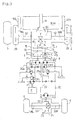
- Fig. 2 is a schematic plan view of a working vehicle provided with mowers, employing a basic driving system of a first group according to the present invention;
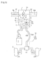
- Fig. 3 is an oil circuit diagram of the same driving system shown in Fig. 1;
- Fig. 4 is a diagram of another driving system of the same, concerning the arrangement of shafts in a
transmission casing 1; - Fig. 5 is a diagram of more another driving system of the same, also concerning the arrangement of shafts in
transmission casing 1; - Fig. 6 is a diagram of an embodiment of the driving system including a transmitting shaft between
transmission casing 1 andsub-driving wheels 6; - Fig. 7 is a diagram of a driving system of the first group, wherein a
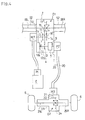
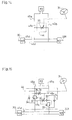
clutch 7 is disposed on output side of a second hydraulic motor M2; - Fig. 8 is a diagram of a driving system of the first group, wherein second hydraulic motor M2 is drivingly changed by turning operation of a
steering operating tool 31; - Fig. 9 is a diagram of another driving system of the first group, wherein second hydraulic M2 is also drivingly changed by turning operation of
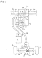
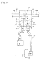
steering operating tool 31; - Fig. 10 is a diagram of a basic driving system of the second group according to the present invention;
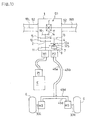
- Fig. 11 is a diagram of a driving system of the second group, wherein
clutches 7 are disposed on output sides of a pair of second hydraulic motors M3; - Fig. 12 is a diagram of a driving system of the second group, wherein the pair of second hydraulic motors M3 are drivingly changed by turning operation of
steering operating tool 31; - Fig. 13 is a diagram of another driving system of the second group, wherein the pair of second hydraulic motors M3 is drivingly changed by turning operation of
steering operating tool 31 through a flowcontrol valve unit 44; - Fig. 14 is a diagram of an embodiment of flow
control valve unit 44; - Fig. 15 is a diagram of another embodiment of flow
control valve unit 44; - Fig. 16 is a diagram of more another embodiment of flow
control valve unit 44; - Fig. 17 is a diagram of a driving system of the second group, wherein the pair of second hydraulic motors M3 are drivingly changed by detection of difference between the rotary speeds of main-and-
sub-driving wheels - Fig. 18 is a diagram of another driving system of the second group, wherein the pair of second hydraulic motors M3 are also drivingly changed by detection of difference between the rotary speeds of main-and-
sub-driving wheels - Fig. 19 is a diagram of a driving system including a single
sub-driving wheel 6, and - Fig. 20 is a sectional plan view of a decelerator.
- Explanation will be given on an embodiment wherein the driving system of the present invention is employed by a mower tractor. As shown in Fig. 1 or others, a pair of front wheels are main-driving
wheels 5 and a pair of rear wheels aresub-driving wheels 6 which are also used as wheels for steering. Main-drivingwheels 5 are supported at a front portion of a vehicle body frame 19 andsub-driving wheels 6 are supported at a rear portion thereof. Triple front reel mowers 8FL, 8FM and 8FR are vertically movably disposed in front of the mower tractor. Double left and right side reel mowers 8SL and 8SR are vertically movably disposed between main-drivingwheels 5 andsub-driving wheels 6. With regard to triple front reel mowers 8FL, 8FM and 8FR, left and right front reel mowers 8FL and 8FR (a pair of side front reel mowers) project forward from the front end of the vehicle body and laterally middle front reel mower (a middle front reel mower) 8FM is disposed behind the both of side front reel mowers 8FL and 8FR. In some cases, only middle front reel mower 8FM may be used. Above the front portion of vehicle body frame 19 is disposed an operating portion A and behind the rear portion thereof is disposed an engine E covered with a bonnet. - As shown in Figs. 1 to 3, each of left and
right axle casings 52 is fixed onto each of left and right sides of atransmission casing 1 and contains each of left andright axles right decelerator casings 29 containing reduction gear (bull gear) train is disposed on the outer end of eachaxle casing 52 so that the reduction gear train is interposed between each ofaxles wheels 5. According to this construction, the ratio of deceleration by a first differential gear unit D1 can be so small as to reduce the transmitting torque thereof, whereby enabling first differential gear unit D1 to be minimized. Also, the width between treads of main-drivingwheels 5 can be changed by means of interposition ofdecelerator casings 29. -
Transmission casing 1, left andright axle casings 52 and left andright decelerator casings 29 are arcuately arranged when viewed in plan, so as to hold a space P between the pair. Middle front reel mower 8FM is disposed in space P so as to be between left and right front wheels (main-driving wheels 5). Then, when triple front reel mowers 8FL, 8FM and 8FR are disposed at the front portion of the vehicle body, the whole of the working vehicle provided with them can be longitudinally short. Also, an arm for lifting middle front reel mower 8FM can be short, and lifting mechanisms for vertically movably suspending left and right front reel mowers 8FL and 8FR can be disposed in space P so as to be protected. Thus, space P betweendecelerator casings 29 can be advantageously utilized. Also, the balance of weight of the mower tractor can be improved so as to stabilize its durability in travelling because of disposal of middle front reel mower 8FM at the center of the vehicle body. -
Axle casings 52 may be integrally formed at left and right sides oftransmission casing 1, or may be integral withdecelerator casings 29. - As shown in Figs. 2, 3 and 20,
decelerator casings 29 project substantially horizontally forward. They can be also disposed substantially vertically so as to raise the level of axles, however, the working vehicle of this embodiment provided for lown mowing prefers low axles so as to have a low center of gravity. Thus,decelerator casings 29 are disposed substantially horizontally, whereby enabling the vehicle provided with the mower or mowers to travel and work easily and steadily on a slope or the like. - Basic portions of vertically moving
links decelerator casings 29 respectively, and are vertically rotated by a hydraulic cylinder (not shown). Vertically movinglinks decelerator casings 29 project more forward. They also require no bracket for attachment thereof. A vertically movinglink 51 is pivoted at its basic portion onto the front surface oftransmission casing 1 and can be vertically rotated by a hydraulic cylinder. Middle front reel mower 8FM is suspended from an utmost end of vertically movinglink 51, which is rotatably supported at its basic portion by the front portion oftransmission casing 1. so as to be vertically rotated by operation of a hydraulic cylinder. - As shown in Fig. 20, each
decelerator casing 29, which can be laterally separated into aleft half casing 29a and aright half casing 29b, is fixed onto an outer end of eachaxle casing 52. An utmost end portion of axle 18 (which isaxle decelerator casing 29 and is rotatably supported by a bearing. With regard to the interior ofdecelerator casing 29, a smalldiametric gear 53 is fixed onto the utmost end portion ofaxle 18. At a front space between the inner sides of left andright half casings decelerator casing 29 is rotatably supported awheel shaft 55 through bearings. A largediametric gear 54 is fixed onto an inner end portion ofwheel shaft 55 and always engages with smalldiametric gear 53, whereby constructing a reduction gear train. An outer end portion ofwheel shaft 55 projects laterally outwardly fromdecelerator casing 29, so that main-driving wheel 5 is fixed onto the outer projecting portion ofwheel shaft 55. - The ratio of deceleration by first differential gear unit D1 can be reduced because of the reduction gear trains contained in
decelerator casings 29, whereby reducing the torque for transmitting by first differential gear unit D1. Thus, first differential gear unit D1 can be compacted, so as to raise the bottom level of the vehicle, whereby expanding space P in its longitudinal direction and the space between front and rear wheels. Also, the width between both treads of main-drivingwheels 5 can be extended because of interposition ofdecelerator casings 29 oraxle casings 52 and can be adjusted if various kinds ofdecelerator casings 29 are prepared. - Next, explanation will be given on various embodiments of driving systems for driving of main-driving
wheels 5 andsub-driving wheels 6 as follows. In this regard, the driving systems of the following embodiments are roughly classified into first and second groups. For the purpose of drivingsub-driving wheels 6, each driving system of the first group uses a single second hydraulic motor M2 and a second differential gear unit D2, and each driving system of the second group uses a pair of second hydraulic motors M3. - At first, a construction of a first HST, which is common in the driving systems of both the first and second groups will be described in accordance with Figs. 3 to 5. As shown in Fig. 3, a first hydraulic pump P1 with variable displacement is connected to an output shaft of engine E. A first hydraulic motor M1 with fixed displacement is attached to
transmission casing 1. First hydraulic pump P1 and first hydraulic motor M1 are fluidly connected with each other through oil passages like pipings, so as to constitute the first HST. An output shaft of first hydraulic motor M1 is connected with aninput shaft 2 supported bytransmission casing 1. - With regard to the interior of
transmission casing 1, asub-transmission 3, which can be shifted stepwise, is contained therein. As shown in Fig. 3, for example,sub-transmission 3 is so constructed that a largediametric gear 10 and a smalldiametric gear 11 are fixed ontoinput shaft 2 and double slidable gears 12 is provided onoutput shaft 4 so as to engage with it through a spline, whereby being axially slidable and not relatively rotatable. When agear 12a of double slidable gears 12 engages with largediametric gear 10,output shaft 4 is rotated fast, and when theother gear 12b thereof engages with smalldiametric gear 11,output shaft 4 is rotated slowly. Thus,sub-transmission 3 can be shifted between two steps of high and low speed states, however, it is not restricted to have two speed steps. It may also have only one gear pattern or more than two gear patterns, or may be also steplessly shifted. - A
gear 13 is fixed onto one end ofoutput shaft 4 and engages with agear 15 provided on adeceleration shaft 14.Bevel gear 16 is also fixed ontodeceleration shaft 14 and engages with aring gear 17 of first differential gear unit D1.Axles wheels 5 are drivingly connected respectively to the utmost ends ofaxles output shaft 4 throughsub-transmission 3 is further given to first differential gear unit D1 throughgears bevel gear 16, whereby driving main-drivingwheels 5. - Other embodiments concerning an inner construction of
transmission casing 1 will be described in accordance with Figs. 4 and 5. In the above mentioned embodiment shown in Fig. 2,transmission casing 1 containsinput shaft 2,output shaft 4 andinput shaft 9, which are arranged perpendicularly toaxles input shaft 2,output shaft 4 andinput shaft 9 are arranged in parallel toaxles bevel gear 16 andbevel ring gear 17 of first differential gear unit D1. The other components are similarly structured as shown in Fig. 2. - With regard to disposal of hydraulic pump and motor P1 and M1, those of the embodiment shown in Fig. 4 are disposed apart from each other respectively on both lateral outer sides of
transmission casing 1 whereas those of the embodiment shown in Fig. 5 are juxtaposed on one side oftransmission casing 1. - Each of the above mentioned embodiments concerning the interior of
transmission casing 1 are shown in Figs. 3 to 5, which belongs to the first group, however, the embodiments can be also employed by the driving systems of the second group. - As shown in Fig. 3, with regard to oil circuits of the first and second HSTs, first hydraulic pump P1 and a charge pump CP1 are driven simultaneously.
Oil passages oil passages check valves 28, so as to supply the operating oil to the closed oil circuit of the first HST. Charge pump CP1 of the first HST can also drive a working machine by pressure oil discharged therefrom. - In such a construction, the rotary speed of
output shaft 4 of first hydraulic pump P1 is steplessly changed by changing slanting angle of a movable swash plate (as a displacement adjusting means) of first hydraulic pump P1, so that main-drivingwheels 5 are rotated at the speed corresponding to the rotary speed ofoutput shaft 4, whereby driving the vehicle. - Next, explanation will be given on a second HST resident in the driving systems of the first group.
Output shaft 4 ofsub-transmission 3 is drivingly connected with first differential gear unit D1 through gears as the above mentioned, so as to drive main-drivingwheels 5, and it is also connected with aninput shaft 9 of a second hydraulic pump P2. - Second hydraulic pump P2 is fluidly connected with second hydraulic motor M2 through a pair of
pipings 20 as a closed fluid circuit, whereby constituting the second HST. Second hydraulic pump and motor P2 and M2 both may have fixed or variable displacements or they may be also constructed so that one of them has variable displacement and the other has fixed displacement in correspondent to their concern with the other components. - The oil circuit of the second HST, which includes a charge pump CP2 or others, is constructed similarly with that of the first HST as shown in Fig. 3.
- A
bevel gear 22 is fixed onto anoutput shaft 21 of second hydraulic motor M2 and engages with aring gear 24 of a second differential gear unit D2 within arear axle housing 23.Sub-driving wheels 6 are fixed respectively onto outer ends of left andright axles - As shown in Fig. 6, a transmitting mechanism including a
universal joint 38 and a transmittingshaft 39 may be interposed between a shaft on output side of sub-transmission 3 (which isoutput shaft 9 on output side ofclutch 7 in the embodiment shown in Fig. 6) and second differential gear unit D2 instead of the second HST, whereby simplifying the power transmitting system therebetween. - Next, construction of a clutch 7 will be described concerning the driving system for
sub-driving wheels 6. In the embodiments shown in Fig. 3 and others, clutch 7 as an over-running clutch or a manual clutch is interposed betweenoutput shaft 4 ofsub-transmission 3 andinput shaft 9 of second hydraulic pump P2 with fixed displacement. Otherwise, clutch 7 as an over-running clutch or a manual clutch may be also disposed on output side of second hydraulic motor M2 with fixed displacement as shown in Fig. 7. In this case,output shaft 4 andinput shaft 9 are directly connected with each other, so that second hydraulic motor M2 always drives when hydraulic pump P2 drives. Output (motor)shaft 21 of second hydraulic motor M2 is separated into a drivingmotor shaft 21a and afollower motor shaft 21b and they can be connected with each other throughclutch 7.Follower motor shaft 21b, which is a shaft on the follower side ofclutch 7, is connected withaxles bevel gear 22,differential ring gear 24 and second differential gear unit D2. - Next, operation of
clutch 7 will be described. In case that clutch 7, which is interposed betweenoutput shaft 4 andinput shaft 9 as shown in Fig. 3, is an over-running clutch, clutch 7 engages betweenoutput shaft 4 andinput shaft 9 when the rotary speed ofinput shaft 9 is slower than that ofoutput shaft 4 without regard to the rotary direction of them (whichevershafts input shaft 9 is the same with or faster than that ofoutput shaft 4. - With regard to driving of
sub-driving wheels 6,sub-driving wheels 6 are rotated by friction against the ground surface when the vehicle travels, so that second hydraulic motor M2 is driven by their rotation, and discharges pressure oil to second hydraulic pump P2, whereby driving itsinput shaft 9. Clutch 7 an over-running clutch automatically acts. - In this regard, clutch 7 engages when
input shaft 9 rotates slower thanoutput shaft 4, and disengages wheninput shaft 9 rotates at the same speed or faster thanoutput shaft 4. - When the vehicle travels on a dry flat road, main-and-
sub-driving wheels input shaft 9 is driven by pressure oil discharged from second hydraulic motor M2, which is driven by the following rotation ofsub-driving wheels 6.Clutch 7 automatically disengages betweenoutput shaft 4 andinput shaft 9 becauseoutput shaft 4 is rotated faster thaninput shaft 9. Thus, second hydraulic pump P2 is not driven andsub-driving wheels 6 are prevented from dragging because of their free of driving, whereby avoiding injuring the ground surface of the farm (lawn). - In travelling, when one of main-driving
wheels 5 falls in mud or a hollow and slips, the travelling speed of the vehicle is reduced whereas the rotary speed ofoutput shaft 4 is kept, so that the rotary speed ofsub-driving wheels 6 becomes relatively lower than that of main-drivingwheels 5. Accordingly, the driving speed of second hydraulic motor M2 is reduced, whereby deceleratinginput shaft 9 of second hydraulic pump P2. Thus, clutch 7 automatically engages betweenoutput shaft 4 andinput shaft 9, so that second hydraulic pump P2 is driven by rotary ofoutput shaft 4, whereby driving second hydraulic motor M2. As a result,sub-driving wheels 6 are driven by second hydraulic motor M2, so that the vehicle travels in four-wheel drive, whereby it can escape from mud or the like. - In case that clutch 7 as an over running clutch is disposed on the output side of second hydraulic motor M2 with fixed displacement as shown in Fig. 7,
clutch 7 disengages when the rotary speed of drivingmotor shaft 21a is the same with or less than that offollower motor shaft 21b. Also, it automatically engages when drivingmotor shaft 21a is rotated faster thanfollower motor shaft 21b. According to this construction, all of the four wheels are rotated at the same speed in normal travelling, so that main-drivingwheels 5 drives second hydraulic motor M2 throughoutput shaft 4 and second hydraulic pump P2. In this case, clutch 7 automatically disengages, so thatfollower motor shaft 21b is not driven, whereby the vehicle travels in two-wheel drive. When either main-driving wheel 5 or both slip, the travelling speed of the vehicle is reduced, so that the rotary speed ofsub-driving wheels 6 becomes relatively lower than that of main-drivingwheels 5. Thus, clutch 7 automatically engages between drivingmotor shaft 21a andfollower motor shaft 21b, whereby driving second differential gear unit D2. As a result,sub-driving wheels 6 are driven by second differential gear unit D2, so that the vehicle travels in four-wheel drive. - With regard to both embodiments shown in Fig. 3 and 7,
clutch 7 may be also a manual clutch, which can be switched on and off by manual operation of a lever. Otherwise, clutch 7 may be also an electromagnetic clutch, which can be switched by operation of a switch. - Furthermore, clutch 7 may be also constructed so as to engage when the difference between the rotary speeds of left and
right axles - Next, embodiments of construction for avoiding dragging in turning will be described in accordance with Figs. 8 and 9. For the embodiment shown in Fig. 8,
clutch 7 is made as an electromagnetic clutch, which can be manually switched by operation of a switch or the like. Either or both of second hydraulic pump P2 and second hydraulic motor M2 of the second HST (in this embodiment, second hydraulic motor M2) have variable displacement. The electromagnetic clutch and a movable swash plate of second hydraulic pump or motor P2 or M2 with variable displacement are connected to a steering operating tool (a steering wheel) 31. - According to such a construction, when the vehicle travels in two-wheel drive (only main-driving
wheels 5 are driven), the electromagnetic clutch is unconnected, so thatsub-driving wheels 6 are steered by operation ofsteering operating tool 31 similarly with the conventional construction. When either or both of main-drivingwheels 6 slip, the switch is turned on so as to connect the electromagnetic clutch, so that the vehicle travels in four-wheel drive, so as to escape. In this construction, an over-running clutch may be also provided in addition to the electromagnetic clutch, whereby requiring no manual operation to switch the clutch between two-wheel drive and four-wheel drive. - When the electromagnetic clutch is connected so as to strengthen the grip of the vehicle on the ground for the purpose of stead travelling unless the vehicle is stuck, the movable swash plate as a displacement adjusting means of second hydraulic motor M2 in straight travelling is shifted so as to coincide the rotary speed of
sub-driving wheels 6 to that of main-drivingwheels 5. In turning operation ofsteering operating tool 31, the degree of slanting of the movable swash plate is reduced in inverse proportion to the degree of rotation of steering operatingtool 31, so thatsub-driving wheels 6 are accelerated, whereby preventing them from being dragged. - For the embodiment shown in Fig. 9, both of second hydraulic pump and motor P2 and M2 have fixed displacement and a bypass valve V is interposed between the pair of
pipings 20, so as to be connected to steering operatingtool 31. When steering operatingtool 31 is rotated at an angle more than the predetermined angle for turning, bypass valve V is switched so as to communicate betweenpipings 20. Thus, second hydraulic motor M2 is changed to be neutral, so that the vehicle turns in two-wheel drive, whereby being prevented from dragging, which is generated by difference between the rotary speeds of main-and-sub-wheel driving wheels pipings 20 may be also provided, so that bypass valve V is switched so as to communicate betweenpipings 20 when the oil pressure thereof is changed by pumping operation of rotation of second hydraulic motor M2 in turning. - Next, explanation will be given on a driving system for
sub-driving wheels 6, namely a modified second HST, resident in the driving system of the second group in accordance with Figs. 10 to 19. - The modified second HST is so constructed that a pair of left and right second hydraulic motors M3, which have variable or fixed displacement, are fluidly connected with second hydraulic pump P2 in parallel to each other, in stead of second hydraulic motor M2 and differential gear unit D2. In this regard, a pair of an advancing
oil passage 45a and a reversingoil passage 45b like pipings are extended from second hydraulic pump P2 and a pair of branchingoil passages 45d are branched from each of the pair ofoil passages Output shafts Output shafts sub-driving wheels 6 are attached to outer ends of the axles. - An over-running clutch or a manual clutch is used as clutch 7 similarly with that of the first group. For the embodiment shown in Fig. 10 or others, clutch 7 is interposed between
output shaft 4 ofsub-transmission 3 andinput shaft 9 of second hydraulic pump P2. For the embodiment shown in Fig. 11, a pair ofclutches 7 are disposed on output sides of left and right second hydraulic motors M3. In this regard, each ofoutput shafts motor shaft 30a of second hydraulic motor M3 and anaxle 30b onto whichsub-driving wheel 6 is fixed. Each of the pair ofclutches 7 is interposed between each ofmotor shafts 30a and each ofaxles 30b. - The operation of an over-running clutch used as clutch 7 shown in Fig. 10 or others is similar with that of the above described
clutch 7 of the first group shown in Fig. 3 or others. With regard to the operation of the pair ofclutches 7 as over-running clutches shown in Fig. 11. they disengage whenmotor shafts 30a rotate at the same speed with or slower thanaxles 30b, and automatically engages whenmotor shafts 30b rotate faster thanaxles 30b. According to this construction, all of the four wheels are rotated at the same speed in normal travelling, so that main-drivingwheels 5 drives second hydraulic motor M2 throughoutput shaft 4 and second hydraulic pump P2. In this case,clutches 7 automatically disengage, so thataxles 30b are not driven, whereby the vehicle travels in two-wheel drive. When either main-driving wheel 5 or both slip, the travelling speed of the vehicle is reduced, so that the rotary speed ofsub-driving wheels 6 becomes relatively slower than that of main-drivingwheels 5. Thus, each ofclutches 7 automatically engages betweenmotor shaft 30a andaxle 30b, whereby drivingsub-driving wheels 6, so that the vehicle travels in four-wheel drive. - Next, explanation will be given on construction for
prevention sub-driving wheels 6 from being dragged in turning according to Figs. 12 to 18. - For the embodiment shown in Fig. 12, both displacement adjusting means like movable swash plates of the pair of left and right second hydraulic motors M3 with variable displacement interlock with
steering operating tool 31, so thatsub-driving wheels 6 are accelerated in proportion to the degree of turning operation ofsteering operating tool 31, so as to avoid being dragged. - For the embodiment shown in Fig. 13, a flow
control valve unit 44 is interposed on oil passages between second hydraulic pump P2 and the pair of second hydraulic motors M3. Flowcontrol valve unit 44 changes the quantity of passing oil according to turning operation ofsteering operating tool 31, so that the vehicle can be prevented from dragging, whereby enabling it to turn smoothly. - An embodiment of flow
control valve unit 44 will be described according to Fig. 14. Abypass oil passage 45c is interposed betweenoil passages variable diaphragm 32 is provided onbypass oil passage 45c, so as to interlock withsteering operating tool 31.Variable diaphragm 32 is closed tight in proportion of increase of rotational degree of steering operatingtool 31, whereby accelerating the pair of second hydraulic motors M3 for preventingsub-driving wheels 6 from being dragged. - Another embodiment of flow
control valve unit 44 is shown in Fig. 15. - In this regard, a pair of flowing adjusting valves, each of which comprises a
variable diaphragm 32 and arelief valve 33, are provided respectively onoil passages check valves 35 are connected respectively to a pair ofbypass oil passages 45c as primary oil circuits of the flowing adjusting valves. Eachcheck valve 35 is disposed so as to allow the primary pressure oil of each flowing adjusting valve to pass through eachvariable diaphragm 32. A pair ofcheck valves 34 are provided respectively so as to allow the secondary oil of the flowing adjusting valves to flow into the primary oil circuit thereof respectively. Accordingly, the quantity of oil flowing from high pressure portion to low pressure portion is limited, whereby acceleratingsub-driving wheels 6 in turning operation ofsteering operating tool 31 similarly with the above mentioned. - Flow
control valve unit 44 may be also constructed as shown in Fig. 16. In this regard, a pair of variable fixedquotient dividing valves 36 are interposed respectively onoil passages valves 37 are interposed respectively on a pair ofoil passages 45d between left and right second hydraulic motors M3, so that the secondary oil circuit of each variable fixedquotient dividing valve 36 is connected to both primary and secondary oil circuits of each switchingvalve 37. The quantity of oil flowing through variable fixed quotient dividingoil valves 36 can be changed by turning operation ofsteering operating tool 31. Also, when switchingvalves 37 are switched so as to blockoil passages 45d, pressure oil of the quantity corresponding to the steering angle is charged from variable fixed quotient dividingoil valves 36 to left and right second hydraulic motors M2, whereby driving left and rightsub-driving wheels 6. - Embodiments shown in Figs. 17 and 18 describe that second hydraulic pump P2 is changed in its displacement according to judgement of turning by detection of difference of operating oil pressure between left and right second hydraulic motors M3. For the embodiment shown in Fig. 17, second hydraulic pump P2 has variable displacement and its displacement adjusting means like a movable swash plate is connected with an
actuator 40 like a hydraulic cylinder, a solenoid or so on, which is controlled by acontroller 41. Ifactuator 40 is a hydraulic cylinder, it is controlled bycontroller 41 as a servovalve or so on. A reference numeral CP1 designates a charge pump for driving the hydraulic cylinder.Controller 41 recognizes the vehicle in turning when it detects that the pressure of oil charged from second hydraulic pump P2 to left second hydraulic motor M3 is different from that to right second hydraulic motor M3. Then, the quantity of oil discharged from second hydraulic pump P2 is increased, so thatsub-driving wheels 6 are accelerated, whereby being prevented from being dragged. - For the embodiment shown in Fig. 18, a switching
valve 42 and a pressuredifference detecting valve 43 are replaced for a servovalve incontroller 41. Switchingvalve 42 with two switching stages is interposed betweenactuator 40 and charge pump CP2 and is switched by pilot pressure oil flowing from pressuredifference detecting valve 43 through a pilot oil passage 46. Pressuredifference detecting valve 43 is switched by the difference of the pressure oil between a pair ofpilot oil passages 47, which are branched respectively from the pair ofoil passages 45d connecting left and right second hydraulic motors M3 with each other. When there is no oil pressure difference betweenoil passages 45d in case of straight travelling, pressuredifference detecting valve 43 and switchingvalve 42 are not switched. When the difference is generated because of turning, pressuredifference detecting valve 43 is switched, so that pilot pressure oil flows into pilot oil passage 46. Thus, switchingvalve 42 is switched so as to driveactuator 40. Accordingly, the oil discharged from second hydraulic pump P2 is increased, so as to accelerate left and right second hydraulic motors M3, whereby preventingsub-driving wheels 6 from being dragged. - With regard to the embodiment shown in Figs. 17 or 18,
controller 40 andactuator 41 may be also connected to left and right second hydraulic motor M3. Otherwise, these embodiment may be also employed by the driving systems of the first group, so thatcontroller 40 andactuator 41 are connected to second hydraulic pump P2 or second hydraulic motor M2. - Furthermore, for the embodiment shown in Fig. 19, a single
sub-driving wheel 6 is provided.Sub-driving wheel 6 is attached to anoutput shaft 30 of a single hydraulic motor M3. Thus, only singlesub-driving wheel 6 is required to drive singlesub-driving wheel 6 and differential gear unit D2 is omitted, whereby simplifying the driving system, so as to be suitable to a small mower tractor. - The present invention described up to here has effect as the follows:
- At first, since the output power of
mechanical sub-transmission 3 drivingly connected withoutput shaft 2 of first hydraulic motor M1, which is fluidly connected with first hydraulic pump P1 driven by power of engine E through the closed fluid circuit, is given to main-drivingwheels 5 and is also given to second hydraulic pump P2 fluidly connected with second hydraulic motor M2 for drivingsub-driving wheels 6,sub-driving wheels 6 can be optionally changed by second hydraulic pump P2 and second hydraulic motor M2 according to stepless transmitting of first hydraulic pump and motor P1 and M1, so that the vehicle can be switched between four-wheel drive and two-wheel drive easily and second hydraulic pump P2 can be rotated at correspondent speed to adjustment of travelling speed. - In this construction, since main-driving
wheels 5 are driven by first hydraulic motor M1 andsub-driving wheels 6 are driven thereby throughclutch 7 as an over-running clutch, driving power is automatically transmitted intosub-driving wheels 6 in case of slipping of either of main-drivingwheels 5, so that the vehicle can escape from being stuck easily, whereby preventing the lawn from being injured. In case that clutch 7 is a manual clutch, manual operation of connecting clutch 7 enables the vehicle to escape from being stuck easily. - Also, since
clutch 7 as an over-running clutch is interposed betweenoutput shaft 4 ofsub-transmission 3 andinput shaft 9 of second hydraulic pump P2, changing of the rotary speeds of main-and-sub-driving wheels sub-driving wheels 6. - Since second hydraulic pump P2 or motor M2 has variable displacement, the rotary speed of
sub-driving wheels 6 can be changed easily. - Also, since second hydraulic pump P2 or motor M2 with variable displacement is connected with steering operating
tool 31 so as to increase the rotary speed ofsub-driving wheels 6 in proportion to the degree of turning operation ofsteering operating tool 31,sub-driving wheels 6 can be accelerated correspondingly to the radius of turning circle, whereby enabling the vehicle to turn easily. - Since
output shaft 2 of first hydraulic pump P1 andoutput shaft 14 ofsub-transmission 3 are longitudinally disposed and drivingly connected to first differential gear unit D1 for main-drivingwheels 5 throughbevel gears transmission casing 1 can be laterally narrow, so as to be compacted. - Otherwise, since
output shaft 2 of first hydraulic pump P1 andoutput shaft 14 ofsub-transmission 3 are laterally disposed, they can be drivingly connected to first differential gear unit D1 for main-drivingwheels 5 through plain gears 16' and 17', whereby improving the efficiency of transmitting into second differential gear unit D1 andtransmission casing 1 can be longitudinally short, so as to be compacted. - Secondly, since the output power of
mechanical sub-transmission 3 drivingly connected with anoutput shaft 2 of first hydraulic motor M1, which is fluidly connected with first hydraulic pump P1 driven by power of engine through the closed fluid circuit, is given to main-drivingwheels 5 through first differential gear unit D1 and is also given to second hydraulic pump P2 fluidly connected with second hydraulic motor M2 for drivingsub-driving wheels 6 through second differential gear unit D2,axles wheels 5 andaxles sub-driving wheels 6 are fluidly connected, so that a transmitting shaft is not required to be disposed at the venter portion of the vehicle, whereby enabling a space betweenaxles axles - Thirdly, since the output power of
mechanical sub-transmission 3 drivingly connected with anoutput shaft 2 of first hydraulic motor M1, which is fluidly connected with first hydraulic pump P1 driven by power of engine through the closed fluid circuit, is given to main-drivingwheels 5 through first differential gear unit D1 and is also given to second hydraulic pump P2 fluidly connected with a pair of left and right second hydraulic motors M3 for driving left and rightsub-driving wheels 6 respectively,axle casing 23 containingaxles sub-driving wheels 6 therein can be compacted and lightened. - In this construction, since second hydraulic pump P2 or left and right hydraulic motors M3, which have variable displacement, is connected with steering operating
tool 31 so as to increase the rotary speed ofsub-driving wheels 6 in proportion to the degree of turning operation ofsteering operating tool 31, the rotary speed ofsub-driving wheels 6 can be correspondent to the degree of turning circle when turning, so that the vehicle can turn smoothly without dragging ofsub-driving wheels 6. - Otherwise, since flow
control valve unit 44 interposed on the oil circuit between second hydraulic pump P2 and second hydraulic motors M3 is connected with steering operating tool, the similar effect can be obtained. - Furthermore, since the pair of
decelerator casings 29, disposed on both lateral sides of left and rightfront axle casings 52 respectively, project horizontally forward, space P can be provided between left andright decelerator casings 29, so that a working machine like middle front reel mower 8FM provided in space P can be disposed compactly and protected by deceleratorcasings 29 anddriving wheels sub-driving wheels - A lifting mechanism for the working machines like triple front reel mowers 8FL, 8FM and 8FR can be also disposed in space P, so that space P can be advantageously utilized. Also, it can be disposed at longitudinally and laterally middle of the vehicle body, whereby giving the vehicle a good balance of weight and enabling it to travel steadily.
- Furthermore, since each
decelerator casing 29 is not disposed vertically but disposed horizontally, the vehicle body can have a low center of gravity, so as to travel steadily.
Claims (8)
- A vehicle driving system comprising:unsteerable drive wheels (5);steerable drive wheels (6);a first hydraulic pump (P1) driven by a prime mover (E);a first hydraulic motor (M1) fluidly connected to the first hydraulic pump (P1); anda multi-step transmission (3) drivingly interposed between the first hydraulic motor (M1) and the unsteerable drive wheels (5);characterized by:a second hydraulic pump (P2) driven by the multi-speed transmission (3); anda second hydraulic motor (M2) fluidly connected to the second hydraulic pump (P2) so as to drive the steerable drive wheels (6), wherein an output force of the second hydraulic motor (M2) is changed when the steerable drive wheels (6) are steered.
- The vehicle driving system according to claim 1, wherein the change of output force of the second hydraulic motor (M2) depends on changing a rotary speed of the second hydraulic motor (M2).
- The vehicle driving system according to claim 1, wherein the change of output force of the second hydraulic motor (M2) depends on clutching on/off power transmission to the second hydraulic motor (M2).
- The vehicle driving system according to claim 1, 2 or 3, wherein a differential unit (D2) differentially connects the left and right steerable drive wheels (6) and is drivingly connected to the second hydraulic motor (M2).
- The vehicle driving system according to claim 1, wherein a pair of second hydraulic motors (M3;M3), serving as the second hydraulic motor (M2), are drivingly connected to the respective left and right steerable drive wheels (6) and fluidly connected in parallel to the second hydraulic pump (P2).
- The vehicle driving system according to claim 5, wherein the change of output force of the second hydraulic motors (M3;M3) depends on changing rotary speeds of the respective second hydraulic motors (M3;M3).
- The vehicle driving system according to claim 6,wherein displacements of the second hydraulic motors (M3;M3) are changed by steering the steerable drive wheels (M3;M3).
- The vehicle driving system according to claim 6, wherein a flow control valve (44) controls the quantity of fluid from the second hydraulic pump (P2) to the second hydraulic motors (M3;M3) according to the steering of the steerable drive wheels (6).
Applications Claiming Priority (3)
| Application Number | Priority Date | Filing Date | Title |
|---|---|---|---|
| JP19599897A JPH1134676A (en) | 1997-07-22 | 1997-07-22 | Apparatus for driving working vehicle |
| JP20040397A JPH1142948A (en) | 1997-07-25 | 1997-07-25 | Traveling drive device of working vehicle |
| EP98112795A EP0893296B1 (en) | 1997-07-22 | 1998-07-09 | Driving system for a working vehicle |
Related Parent Applications (1)
| Application Number | Title | Priority Date | Filing Date |
|---|---|---|---|
| EP98112795A Division EP0893296B1 (en) | 1997-07-22 | 1998-07-09 | Driving system for a working vehicle |
Publications (1)
| Publication Number | Publication Date |
|---|---|
| EP1745973A1 true EP1745973A1 (en) | 2007-01-24 |
Family
ID=26509465
Family Applications (2)
| Application Number | Title | Priority Date | Filing Date |
|---|---|---|---|
| EP98112795A Expired - Lifetime EP0893296B1 (en) | 1997-07-22 | 1998-07-09 | Driving system for a working vehicle |
| EP06122900A Withdrawn EP1745973A1 (en) | 1997-07-22 | 1998-07-09 | Driving system for a working vehicle |
Family Applications Before (1)
| Application Number | Title | Priority Date | Filing Date |
|---|---|---|---|
| EP98112795A Expired - Lifetime EP0893296B1 (en) | 1997-07-22 | 1998-07-09 | Driving system for a working vehicle |
Country Status (3)
| Country | Link |
|---|---|
| US (2) | US6196348B1 (en) |
| EP (2) | EP0893296B1 (en) |
| DE (1) | DE69836845T2 (en) |
Cited By (1)
| Publication number | Priority date | Publication date | Assignee | Title |
|---|---|---|---|---|
| CN107191510A (en) * | 2017-07-01 | 2017-09-22 | 刘剑 | The two of vehicle drive and 4 wheel driven automatic switching control equipment |
Families Citing this family (50)
| Publication number | Priority date | Publication date | Assignee | Title |
|---|---|---|---|---|
| DE69836845T2 (en) * | 1997-07-22 | 2007-10-18 | Kanzaki Kokyukoki Mfg. Co., Ltd., Amagasaki | Drive for a work vehicle |
| US6951259B2 (en) * | 1998-12-03 | 2005-10-04 | Koji Irikura | Multi-wheel vehicle |
| US6629577B1 (en) | 1998-07-02 | 2003-10-07 | Tuff Torq Corporation | Driving apparatus for speed changing and steering of a vehicle |
| US6126564A (en) * | 1998-07-08 | 2000-10-03 | Kanzaki Kokyukoki Mfg. Co., Ltd. | Axle driving apparatus |
| US6578656B2 (en) * | 1998-09-03 | 2003-06-17 | Kubota Corporation | Riding mower |
| US6540633B1 (en) * | 1998-09-25 | 2003-04-01 | Tuff Torq Corporation | Transmission for speed changing and steering of a vehicle |
| US6397966B1 (en) | 1999-01-22 | 2002-06-04 | Kanzaki Kokyukoki, Mfg. Co., Ltd. | Vehicle improved in steering |
| US6547685B2 (en) | 1999-01-22 | 2003-04-15 | Kanzaki Kokyukoki Mfg. Co., Ltd. | Transaxle apparatus |
| JP4116735B2 (en) * | 1999-06-02 | 2008-07-09 | 本田技研工業株式会社 | Driving force control device for four-wheel drive vehicle |
| US6913103B2 (en) * | 2000-02-03 | 2005-07-05 | Yanmar Co., Ltd. | Hydraulically driven traveling vehicle |
| US6776248B2 (en) * | 2001-10-29 | 2004-08-17 | Jeffery D. Campbell | Four wheel drive motorized carrier |
| JP2003136988A (en) * | 2001-10-30 | 2003-05-14 | Kanzaki Kokyukoki Mfg Co Ltd | Traveling transmission mechanism for vehicle |
| JP3907452B2 (en) | 2001-11-27 | 2007-04-18 | 株式会社クボタ | Mower |
| JP3950358B2 (en) * | 2002-04-24 | 2007-08-01 | 株式会社 神崎高級工機製作所 | Steering device for work vehicle |
| ITRE20020062A1 (en) * | 2002-07-29 | 2004-01-29 | Gianni Ferrari S R L | STEERING SYSTEM FOR FOUR WHEEL VEHICLES |
| JP4049646B2 (en) * | 2002-09-24 | 2008-02-20 | 株式会社クボタ | Work vehicle |
| JP4115227B2 (en) * | 2002-09-26 | 2008-07-09 | 株式会社クボタ | Mower |
| US6732828B1 (en) * | 2002-10-22 | 2004-05-11 | Robert Abend | Hydraulically driven vehicle |
| JP4263459B2 (en) * | 2002-10-25 | 2009-05-13 | 富士重工業株式会社 | Vehicle differential limiting control device |
| JP4131816B2 (en) * | 2002-12-27 | 2008-08-13 | 株式会社 神崎高級工機製作所 | Driving device for traveling vehicle |
| ATE487634T1 (en) | 2003-01-08 | 2010-11-15 | Kanzaki Kokyukoki Mfg Co Ltd | HYDRAULIC AXLE DRIVE DEVICE |
| JP2004217111A (en) * | 2003-01-16 | 2004-08-05 | Komatsu Ltd | Transmission of wheel type work vehicle |
| JP4040492B2 (en) * | 2003-02-24 | 2008-01-30 | 株式会社クボタ | Work vehicle travel control device |
| JP2004330829A (en) * | 2003-05-02 | 2004-11-25 | Kanzaki Kokyukoki Mfg Co Ltd | Steering drive device for traveling vehicle |
| US6904985B2 (en) * | 2003-05-21 | 2005-06-14 | Deere & Company | Transmission control device for vehicles and steering assembly for vehicles |
| US6935454B1 (en) * | 2003-09-18 | 2005-08-30 | Hydro-Gear Limited Partnership | Valve for a hydraulic drive apparatus |
| US7316114B1 (en) | 2003-09-18 | 2008-01-08 | Hydro-Gear Limited Partnership | Valve for a hydraulic drive apparatus |
| US7204779B2 (en) * | 2003-09-26 | 2007-04-17 | Koji Irikura | Hydraulic steering transaxle and hydraulic driving vehicle |
| JP4266781B2 (en) * | 2003-11-11 | 2009-05-20 | 株式会社 神崎高級工機製作所 | Pumping unit |
| JP2005297923A (en) * | 2004-04-15 | 2005-10-27 | Kanzaki Kokyukoki Mfg Co Ltd | Four-wheel drive vehicle |
| US7383913B1 (en) * | 2004-09-02 | 2008-06-10 | Kanzaki Kokyukoki Mfg. Co., Ltd. | Hydraulic transaxle and vehicle comprising it |
| GB0514998D0 (en) * | 2005-07-21 | 2005-08-31 | E2V Tech Uk Ltd | Sensor with trigger pixels for imaging of pulsed radiation |
| US7559397B2 (en) * | 2005-08-12 | 2009-07-14 | Tai-Her Yang | Energy storage type of dual-drive coupled power distribution system |
| US7607505B2 (en) * | 2005-08-12 | 2009-10-27 | Tai-Her Yang | Energy storage type of differential mixed power distribution system |
| US7739870B2 (en) | 2006-08-04 | 2010-06-22 | Briggs And Stratton Corporation | Hydrostatic transmission |
| US7614227B2 (en) | 2006-08-04 | 2009-11-10 | Briggs And Stratton Corporation | Rotary control valve for a hydrostatic transmission |
| EP1897740B1 (en) * | 2006-09-05 | 2019-03-20 | Kanzaki Kokyukoki Mfg. Co., Ltd. | Wheel motor device |
| JP5097894B2 (en) * | 2006-09-05 | 2012-12-12 | 株式会社 神崎高級工機製作所 | Work vehicle |
| DE102007015668B4 (en) * | 2007-03-31 | 2016-02-25 | Iseki & Co. Ltd. | Riding Mowers |
| US7669683B2 (en) * | 2007-12-04 | 2010-03-02 | Tai-Her Yang | Energy storage type of dual-drive coupled power distribution system |
| US20100146960A1 (en) * | 2008-12-17 | 2010-06-17 | Caterpillar Inc. | Externally mounted variator for split torque transmission |
| CN101879864A (en) * | 2010-05-18 | 2010-11-10 | 覃志明 | Four-wheel drive wheeled tractor with hydraulically driven front axle |
| US9597959B2 (en) | 2013-02-11 | 2017-03-21 | Dana Belgium N.V. | Hydrostatic and direct drive transmission |
| DE102013108674A1 (en) * | 2013-08-09 | 2015-02-12 | Krauss-Maffei Wegmann Gmbh & Co. Kg | vehicle |
| CN104129293A (en) * | 2014-07-29 | 2014-11-05 | 柳州市宏大机械制造有限公司 | Tractor |
| EP3356356B1 (en) | 2015-10-01 | 2021-05-26 | Firmenich Incorporated | Compounds useful as modulators of trpm8 |
| CN108138928B (en) * | 2015-10-13 | 2021-06-25 | 株式会社神崎高级工机制作所 | hydraulic transmission |
| US9702458B2 (en) | 2015-12-07 | 2017-07-11 | Caterpillar Inc. | Pressure and speed control for a vehicle |
| JP7296833B2 (en) * | 2019-09-12 | 2023-06-23 | 株式会社マキタ | work machine |
| CN113767871A (en) * | 2021-09-10 | 2021-12-10 | 南方海洋科学与工程广东省实验室(湛江) | Shore-based feeding robot and power transmission system and control method thereof |
Citations (6)
| Publication number | Priority date | Publication date | Assignee | Title |
|---|---|---|---|---|
| JPS60139533A (en) * | 1983-12-28 | 1985-07-24 | Mazda Motor Corp | Four-wheel drive vehicle |
| JPS63159134A (en) * | 1987-12-11 | 1988-07-02 | Kanzaki Kokyukoki Mfg Co Ltd | Transmission of self-running working vehicle |
| US4886142A (en) * | 1987-06-26 | 1989-12-12 | Kanzaki Kokyukoki Mfg. Co. Ltd. | Hydraulic four-wheel drive system |
| JPH082279A (en) | 1994-06-20 | 1996-01-09 | Kanzaki Kokyukoki Mfg Co Ltd | Four-wheel drive unit for work vehicle |
| DE19522877A1 (en) * | 1994-07-25 | 1996-02-01 | Kanzaki Kokyukoki Mfg Co Ltd | Drive for tractor etc. with hydrostatic transmission |
| JPH0966749A (en) * | 1995-08-31 | 1997-03-11 | Kubota Corp | Hydraulic circuit structure of work vehicle |
Family Cites Families (16)
| Publication number | Priority date | Publication date | Assignee | Title |
|---|---|---|---|---|
| US3702642A (en) * | 1970-10-21 | 1972-11-14 | Clarence Kirk Greene | Hydraulic drive for vehicles using hydraulic motors |
| US3913697A (en) * | 1973-03-16 | 1975-10-21 | Clarence Kirk Greene | Vehicle having a power take-off and a hydraulic motor, and method of driving same |
| US3874470A (en) * | 1973-05-31 | 1975-04-01 | Clarence Kirk Greene | Pressure-responsive displacement changer for vehicular drive system having a variable displacement pump |
| US3994353A (en) * | 1975-06-23 | 1976-11-30 | Clarence Kirk Greene | Vehicle having a mechanical drive, a pump, a variable-displacement motor and a method of driving the vehicle |
| US4399886A (en) * | 1980-12-09 | 1983-08-23 | Sundstrand Corporation | Controls for variable displacement motor and motors |
| DE3308295A1 (en) * | 1983-03-09 | 1984-09-13 | Zahnradfabrik Friedrichshafen Ag, 7990 Friedrichshafen | VEHICLE |
| JPS6032127A (en) | 1983-08-02 | 1985-02-19 | Hitachi Condenser Co Ltd | Production of magnetic recording medium |
| US4771852A (en) * | 1985-06-05 | 1988-09-20 | Toyota Jidosha Kabushiki Kaisha | Four wheel drive vehicle transfer and control apparatus |
| JPH01136830A (en) * | 1987-11-20 | 1989-05-30 | Honda Motor Co Ltd | Front and rear wheel drive force distribution control device |
| EP0380101A3 (en) * | 1989-01-27 | 1991-05-29 | Toyoda Koki Kabushiki Kaisha | Driving power transmission system for vehicle |
| US5074580A (en) * | 1990-08-28 | 1991-12-24 | Clark Equipment Company | Torsion bar suspension assembly for an articulated vehicle |
| US5687808A (en) * | 1994-03-18 | 1997-11-18 | Nissan Motor Co., Ltd. | Four wheel drive mechanism |
| US5699871A (en) * | 1994-09-21 | 1997-12-23 | Nissan Motor Co., Ltd. | Driving force transfer apparatus for four-wheel drive vehicle |
| JPH09121645A (en) | 1995-10-31 | 1997-05-13 | Kubota Corp | Lawn mower |
| JP3255012B2 (en) * | 1996-05-02 | 2002-02-12 | トヨタ自動車株式会社 | Hybrid car |
| DE69836845T2 (en) * | 1997-07-22 | 2007-10-18 | Kanzaki Kokyukoki Mfg. Co., Ltd., Amagasaki | Drive for a work vehicle |
-
1998
- 1998-07-09 DE DE69836845T patent/DE69836845T2/en not_active Expired - Fee Related
- 1998-07-09 EP EP98112795A patent/EP0893296B1/en not_active Expired - Lifetime
- 1998-07-09 EP EP06122900A patent/EP1745973A1/en not_active Withdrawn
- 1998-07-21 US US09/119,631 patent/US6196348B1/en not_active Expired - Fee Related
-
2001
- 2001-01-09 US US09/756,235 patent/US6401854B2/en not_active Expired - Fee Related
Patent Citations (6)
| Publication number | Priority date | Publication date | Assignee | Title |
|---|---|---|---|---|
| JPS60139533A (en) * | 1983-12-28 | 1985-07-24 | Mazda Motor Corp | Four-wheel drive vehicle |
| US4886142A (en) * | 1987-06-26 | 1989-12-12 | Kanzaki Kokyukoki Mfg. Co. Ltd. | Hydraulic four-wheel drive system |
| JPS63159134A (en) * | 1987-12-11 | 1988-07-02 | Kanzaki Kokyukoki Mfg Co Ltd | Transmission of self-running working vehicle |
| JPH082279A (en) | 1994-06-20 | 1996-01-09 | Kanzaki Kokyukoki Mfg Co Ltd | Four-wheel drive unit for work vehicle |
| DE19522877A1 (en) * | 1994-07-25 | 1996-02-01 | Kanzaki Kokyukoki Mfg Co Ltd | Drive for tractor etc. with hydrostatic transmission |
| JPH0966749A (en) * | 1995-08-31 | 1997-03-11 | Kubota Corp | Hydraulic circuit structure of work vehicle |
Cited By (2)
| Publication number | Priority date | Publication date | Assignee | Title |
|---|---|---|---|---|
| CN107191510A (en) * | 2017-07-01 | 2017-09-22 | 刘剑 | The two of vehicle drive and 4 wheel driven automatic switching control equipment |
| CN107191510B (en) * | 2017-07-01 | 2021-01-22 | 苏州埃博斯电气有限公司 | Automatic switching device for two-wheel drive and four-wheel drive of vehicle |
Also Published As
| Publication number | Publication date |
|---|---|
| US20010001187A1 (en) | 2001-05-17 |
| DE69836845D1 (en) | 2007-02-22 |
| US6401854B2 (en) | 2002-06-11 |
| EP0893296A2 (en) | 1999-01-27 |
| US6196348B1 (en) | 2001-03-06 |
| EP0893296B1 (en) | 2007-01-10 |
| DE69836845T2 (en) | 2007-10-18 |
| EP0893296A3 (en) | 2001-10-31 |
Similar Documents
| Publication | Publication Date | Title |
|---|---|---|
| EP0893296B1 (en) | Driving system for a working vehicle | |
| US6732828B1 (en) | Hydraulically driven vehicle | |
| US7980351B2 (en) | Hydraulic transaxle | |
| JP3824665B2 (en) | Work vehicle transmission | |
| US7980339B2 (en) | Power transmission system of hydraulically driven working vehicle | |
| US7971675B2 (en) | Hydraulic transaxle and vehicle comprising it | |
| US7314110B1 (en) | Hydraulic drive vehicle | |
| US6932179B2 (en) | Hydraulic four-wheel driving apparatus | |
| US8205708B2 (en) | Hydraulic transaxle | |
| US7591338B2 (en) | Hydraulic transaxle and vehicle comprising it | |
| JP2005155686A5 (en) | ||
| US7228685B2 (en) | Axle driving apparatus | |
| US6874320B2 (en) | Axle driving apparatus | |
| JPH1134676A (en) | Apparatus for driving working vehicle | |
| JP3621403B2 (en) | Work vehicle transmission | |
| AU2004101046A4 (en) | A Hydraulic Drive System for Multi-Speed Vehicle |
Legal Events
| Date | Code | Title | Description |
|---|---|---|---|
| PUAI | Public reference made under article 153(3) epc to a published international application that has entered the european phase |
Free format text: ORIGINAL CODE: 0009012 |
|
| 17P | Request for examination filed |
Effective date: 20061025 |
|
| AC | Divisional application: reference to earlier application |
Ref document number: 0893296 Country of ref document: EP Kind code of ref document: P |
|
| AK | Designated contracting states |
Kind code of ref document: A1 Designated state(s): DE GB |
|
| 17Q | First examination report despatched |
Effective date: 20070530 |
|
| AKX | Designation fees paid |
Designated state(s): DE GB |
|
| STAA | Information on the status of an ep patent application or granted ep patent |
Free format text: STATUS: THE APPLICATION IS DEEMED TO BE WITHDRAWN |
|
| 18D | Application deemed to be withdrawn |
Effective date: 20100128 |