EP1745887A1 - Sanding tool - Google Patents
Sanding tool Download PDFInfo
- Publication number
- EP1745887A1 EP1745887A1 EP06253605A EP06253605A EP1745887A1 EP 1745887 A1 EP1745887 A1 EP 1745887A1 EP 06253605 A EP06253605 A EP 06253605A EP 06253605 A EP06253605 A EP 06253605A EP 1745887 A1 EP1745887 A1 EP 1745887A1
- Authority
- EP
- European Patent Office
- Prior art keywords
- coupling
- sanding
- decoupling element
- restraining
- shoe
- Prior art date
- Legal status (The legal status is an assumption and is not a legal conclusion. Google has not performed a legal analysis and makes no representation as to the accuracy of the status listed.)
- Withdrawn
Links
- 230000000452 restraining effect Effects 0.000 claims abstract description 79
- 235000014443 Pyrus communis Nutrition 0.000 description 4
- 230000009977 dual effect Effects 0.000 description 3
- 238000010276 construction Methods 0.000 description 2
- 230000008878 coupling Effects 0.000 description 1
- 238000010168 coupling process Methods 0.000 description 1
- 238000005859 coupling reaction Methods 0.000 description 1
- 230000003028 elevating effect Effects 0.000 description 1
- 238000004519 manufacturing process Methods 0.000 description 1
Images




Classifications
-
- B—PERFORMING OPERATIONS; TRANSPORTING
- B24—GRINDING; POLISHING
- B24B—MACHINES, DEVICES, OR PROCESSES FOR GRINDING OR POLISHING; DRESSING OR CONDITIONING OF ABRADING SURFACES; FEEDING OF GRINDING, POLISHING, OR LAPPING AGENTS
- B24B23/00—Portable grinding machines, e.g. hand-guided; Accessories therefor
- B24B23/02—Portable grinding machines, e.g. hand-guided; Accessories therefor with rotating grinding tools; Accessories therefor
- B24B23/03—Portable grinding machines, e.g. hand-guided; Accessories therefor with rotating grinding tools; Accessories therefor the tool being driven in a combined movement
-
- B—PERFORMING OPERATIONS; TRANSPORTING
- B24—GRINDING; POLISHING
- B24B—MACHINES, DEVICES, OR PROCESSES FOR GRINDING OR POLISHING; DRESSING OR CONDITIONING OF ABRADING SURFACES; FEEDING OF GRINDING, POLISHING, OR LAPPING AGENTS
- B24B23/00—Portable grinding machines, e.g. hand-guided; Accessories therefor
- B24B23/04—Portable grinding machines, e.g. hand-guided; Accessories therefor with oscillating grinding tools; Accessories therefor
Definitions
- the present invention relates to a sanding tool capable of selectively performing random orbital sanding or regular orbital sanding.
- a sanding tool is either a random orbital sander or a regular orbital sander.
- a random orbital sander an oscillating disc rotates independently of the motor and performs random orbital movement.
- Such a sander is in general used for removing relatively large quantities of material.
- a regular orbital sander an oscillating disc cannot rotate independently of the motor and performs regular orbital movement.
- Such a sander is in general used for removing relatively small quantities of material (for example for detailed work or for finishing). If a user wishes to have the ability to perform both coarse and detailed sanding, it has been in general necessary to purchase both a random orbital sander and a regular orbital sander.
- US-A-6132300 discloses a dual function sander. Oscillating discs may be selectively mounted on the sander by connection means to perform random orbital sanding or regular orbital sanding.
- the connection means includes a plurality of rigid elements and a plurality of flexible columns and is complex to manufacture. The flexible columns are easily invalidated and high quality materials are required which increase costs. Additionally the oscillating discs must be changed to perform random sanding or regular sanding which is troublesome and inconvenient to a user.
- US-B-6739493 discloses a sander with a gear.
- the gear has a switch device and at least two types of grinding wheel motion can be pre-selected by means of the switch device.
- the switch device has a two-part housing and a switching ring having a grip. The grip extends through a slot in the housing and the switching ring cooperates with two pear wheels that mesh with each other.
- the switch device includes two locking bolts cooperating with at least one recess in the first pear wheel or the second pear wheel such that the sander may be described as a twin speed regular sander. When the locking bolts are disconnected from the recesses in the two pear wheels, the sander can be described as a random orbital sander. Such a sander needs many elements and the construction is complex and costly. Furthermore the two locking bolts rigidly connected to the switching ring produces strong vibrations.
- EP-A-0525328 discloses a sander with a rotating drive motor and a grinding disc driven by the motor via an eccentric device. This can be changed from a random orbital sander to a regular orbital sander by an auxiliary device.
- the auxiliary device is assembled in the housing and the grinding disc, the sander can be described as a regular orbital sander.
- the auxiliary device is disassembled, the sander can be described as a random orbital sander.
- the user assembles and disassembles the auxiliary device to perform both random orbital sanding and regular orbital sanding which is troublesome and inconvenient.
- the present invention seeks to improve dual function sanding tools by exploiting a simple coupling-decoupling element.
- the present invetion provides a sanding tool comprising:
- the coupling-decoupling element of the sanding tool of the present invention advantageously couples or decouples the restraining element and the sanding shoe with minimal elements and a simple construction produced at low cost.
- the coupling-decoupling element is convenient for the user to change function.
- the restraining element is flexibly mounted on the housing which will produce less vibrations and improve comfort.
- the coupling-decoupling element is rotational between the first position and the second position.
- the coupling-decoupling element may be rotational substantially in a horizontal or vertical plane.
- the coupling-decoupling element is slidable ( eg linearly slidable) between the first position and the second position.
- the coupling-decoupling element is elevational relative to the restraining element between the first position and the second position.
- the sanding tool has an operating arm connected to or integral with the coupling-decoupling element.
- the coupling-decoupling element may be disposed (eg axially disposed) between the restraining element and sanding shoe or between the housing and the restraining element.
- the coupling-decoupling element is axially disposed between the restraining element and sanding shoe.
- the restraining element comprises a connecting part for connection to the housing, an elastic part and a restraining part.
- the coupling-decoupling element is movably (eg rollingly or slidingly) connected to the sanding shoe, wherein in the first position the coupling-decoupling element is disconnected from the restraining element and in the second position the coupling-decoupling element is connected to the restraining element.
- the coupling-decoupling element is movably (eg rollingly or slidingly) connected to the restraining element, wherein in the first position the coupling-decoupling element is disconnected from the sanding shoe and in the second position the coupling-decoupling element is connected to the sanding shoe.
- the coupling-decoupling element is synchronously disconnected from the restraining element and the sanding shoe and in the second position the coupling-decoupling element is synchronously connected to the restraining element and the sanding shoe.
- the coupling-decoupling element is disposed between the housing and the restraining element and in the first position the coupling-decoupling element is synchronously disconnected from the restraining element and the sanding shoe and in the second position the coupling-decoupling element is synchronously connected with the restraining element and the sanding shoe.
- the coupling-decoupling element comprises;
- the second contact surface is typically multi-faceted.
- the coupling-decoupling element rotates (eg rotates substantially in a horizontal or vertical plane) relative to the sanding shoe between the first position and the second position.
- the coupling-decoupling element comprises an operating arm and the sanding shoe has at least one bracket for engaging the operating arm to prevent the coupling-decoupling element from rotating.
- the second contact surface engages the sanding shoe and has at least one curved protrusion contiguous with a first ramp
- the sanding shoe has at least one curved recess contiguous with a second ramp for engaging the curved protrusion and the first ramp respectively and wherein in the first position the curved protrusion engages the curved recess and the first contact surface is disconnected from the restraining part and wherein in the second position the curved protrusion disengages the curved recess and the first contact surface is connected to the restraining part.
- the eccentric device has a plurality of axial containment slots each containing an elastic element between the coupling-decoupling element and the end of the containment slot.
- the eccentric device has a plurality of axial locating columns and the coupling-decoupling element has a plurality of cut away portions, wherein each cut-away portion engages a respective locating column to prevent the coupling-decoupling element from rotating.
- the sanding tool further comprises:
- the first contact face is connected to the second contact surface and the first contact surface is disconnected from the restraining part and wherein in the second position the second contact face is connected to the second contact surface and the first contact surface is connected to the restraining part.
- the eccentric device has a containment slot for containing the coupling-decoupling element.
- the restraining part has a containment slot and the coupling-decoupling element is slidably received in the containment slot, the bearing sleeve has a containment slot for containing the coupling-decoupling element, wherein in the first position the coupling-decoupling element is separated from the containment slot and the restraining element is decoupled from the sanding shoe and in the second position the coupling-decoupling element is received in the containment slot and the restraining element is coupled to the sanding shoe.
- the eccentric device comprises:
- a first embodiment of a sanding tool of the present invention comprises a housing 1 and a drive unit 2 mounted in the housing 1.
- the drive unit 2 comprises a motor 21 which drives a rotary drive shaft 22.
- An eccentric device 4 is mounted eccentrically on the drive unit 2.
- a sanding shoe 7 is fastened axially to the eccentric device 4 at the base of the housing 1.
- the sanding tool further comprises a restraining element 3 flexibly mounted on the housing 1.
- a coupling-decoupling element 6 is axially disposed between the restraining element 3 and the sanding shoe 7.
- the coupling-decoupling element 6 is selectively connected to the restraining element 3 and movably connected to the sanding shoe 7 between a first position in which the restraining element 3 is decoupled from the sanding shoe 7 and a second position in which the restraining element 3 is coupled to the sanding shoe 7.
- the restraining element 3 is substantially annular and comprises an exterior connecting part 31 flexibly fastened to the housing 1 by bolts and an interior restraining part 33 by which the restraining element 3 is selectively connected to the coupling-decoupling element 6. Between the exterior connecting part 31 and the interior restraining part 33 is an intermediate elastic part 32.
- the eccentric device 4 comprises a fan 41 with an eccentric hub 41a on which is radially mounted a bearing 42.
- a bearing sleeve 43 is mounted radially on the bearing 42.
- the eccentric hub 41 a is mounted eccentrically on the drive shaft 22 and the bearing 42 and fan 41 are fastened to the drive shaft 22 by bolts.
- the sanding shoe 7 at the base of the housing 1 is fastened to the bearing sleeve 43 by bolts.
- the bearing sleeve 43 has three axial containment slots 432 substantially equidistantly positioned substantially on its perimeter and a plurality of axial locating columns 431.
- a first end of each of a plurality of springs 5 abuts against the coupling-decoupling element 6 and a second end opposite to the first end abuts against the bearing sleeve 43 in the axial containment slot 432.
- the coupling-decoupling element 6 comprises a mulit-faceted substantially annular main body with a first contact surface 62 and a second contact surface 63.
- the first contact surface 62 engages the first end of each spring 5 and is selectively connected to the interior restraining part 33.
- the second contact surface 63 engages the sanding shoe 7. Extending partially circumferentially along the second contact surface 63 are three curved protrusions 631 each of which is contiguous with a first ramp 632.
- the coupling-decoupling element 6 has three curved cut-away portions 65 at substantially equal intervals on its inner wall.
- Each of the curved cut-away portions 65 comprises a first inner radial surface 651 opposite to a second inner radial surface 652 (as shown in Figure 4) and engages a respective locating column 431 to prevent the coupling-decoupling element 6 from rotating.
- the coupling-decoupling element 6 further comprises a radially outwardly extending operating arm 61.
- the sanding shoe 7 has a bracket 71 engaging the operating arm 61 to prevent the coupling-decoupling element 6 from rotating.
- the bracket 71 comprises a first exterior radial surface 711 and a second exterior radial surface 712.
- the sanding shoe 7 has at least one curved recess 72 engaging the curved protrusion 631 and contiguous with a second ramp 73.
- the first ramp 632 can move along the second ramp 73.
- the coupling-decoupling element 6 is shown in the first position in which the operating arm 61 engages the first exterior radial surface 711 to prevent the coupling-decoupling element 6 from rotating in direction E. Simultaneously the locating column 431 engages the first inner radial surface 651 to prevent the coupling-decoupling element 6 from rotating in direction F.
- a clearance h (about 0.3-0.8 mm) is present between the first contact surface 62 and the interior restraining part 33 such that when the motor 21 rotates the drive shaft 22, the fan 41 and bearing sleeve 43 will be driven to rotate eccentrically relative to the drive shaft 22.
- the sanding shoe 7 will rotate unrestrained with the bearing sleeve 43 and the sanding tool is free to perform random orbital movement.
- the operating arm 61 can be moved from the first position to the second position by elevating the operating arm 61 to compress the springs 5 and then turning the operating arm 61 in a substantially horizontal plane.
- the cutaway portion 65 moves relative to the locating column 431, the first ramp 632 moves along the second ramp 73 and the coupling-decoupling element 6 rotates in direction E.
- the locating column 431 contacts the second inner radial surface 652 to prevent the coupling-decoupling element 6 from rotating in direction F'
- the coupling-decoupling element 6 is in the second position and the operating arm 61 contacts the second exterior radial surface 712 to prevent the coupling-decoupling element 6 from rotating in direction E'.
- the curved protrusion 631 departs the curved recess 72 to close the clearance h so that the first contact surface 62 is connected to the interior restraining part 33.
- the sanding shoe 7 is therefore coupled to the restraining element 3 by the coupling-decoupling element 6.
- the motor 21 actuates the drive shaft 22 to rotate
- the restraining force of the restraining part 33 prevents the sanding shoe 7 from rotating eccentrically relative to the drive shaft 22 and the sanding tool is restrained to perform regular orbital movement.
- a restraining element 3a comprises at the top a substantially annular connecting part 31a for flexible connection to the housing 1, at the bottom a substantially annular restraining part 33a and between the connecting part 31a and the restraining part 33a an elastic part 32a being a plurality of flexible axial columns 321a.
- the flexible columns 321a pass through holes 311a in the periphery of the connecting part 31a to the restraining part 33a.
- the flexible columns 321a are fastened to the restraining part 33a by bolts.
- a plurality of teeth 332a are formed on the inner circumferential underside 311a of the restraining part 33a.
- the coupling-decoupling element 6a is cross-shaped and its first contact surface 62a is selectively engageable with the teeth 332a.
- the sanding tool has an operating arm 61 a comprising an operating handle 612a connected perpendicularly to a connecting rod 66a terminating at each end in an eccentric supporting tip 663a.
- the supporting tips 663a are rollingly disposed on the sanding shoe 7a.
- the connecting rod 66a engages the coupling-decoupling element 6a and comprises a first contact face 661 a and a second contact face 662a.
- the sanding shoe 7a has on its upper face a radial containment groove 75a for containing the operating handle 612a.
- the bearing sleeve 43a of the eccentric device 4 has containment slots 433a for containing the coupling-decoupling element 6a.
- the coupling-decoupling element 6a when the coupling-decoupling element 6a is located in the first position, the first contact face 661a of the connecting rod 66a is connected to the second contact surface 63a of the coupling-decoupling element 6a. In this position, the first contact surface 62a is disengaged from the teeth 332a of the restraining part 33a so that the sanding tool is free to perform random orbital movement.
- the bearing sleeve 43b has a radial containment slot 434b for selective containment of the coupling-decoupling element 6b.
- the coupling-decoupling element 6b has a locating member 68b with a terminal grip 67b and a spring 5b disposed between the locating member 68b and an inner wall 81b of the housing 1b.
- the housing 1b has a radial projection 8b selectively engaging the grip 67b.
- the restraining part 33b has a containment slot 333b in which the coupling-decoupling element 6b is slidably received.
Landscapes
- Engineering & Computer Science (AREA)
- Mechanical Engineering (AREA)
- Finish Polishing, Edge Sharpening, And Grinding By Specific Grinding Devices (AREA)
Abstract
Description
- The present invention relates to a sanding tool capable of selectively performing random orbital sanding or regular orbital sanding.
- In general, a sanding tool is either a random orbital sander or a regular orbital sander. In a random orbital sander, an oscillating disc rotates independently of the motor and performs random orbital movement. Such a sander is in general used for removing relatively large quantities of material. In a regular orbital sander, an oscillating disc cannot rotate independently of the motor and performs regular orbital movement. Such a sander is in general used for removing relatively small quantities of material (for example for detailed work or for finishing). If a user wishes to have the ability to perform both coarse and detailed sanding, it has been in general necessary to purchase both a random orbital sander and a regular orbital sander.
-
US-A-6132300 discloses a dual function sander. Oscillating discs may be selectively mounted on the sander by connection means to perform random orbital sanding or regular orbital sanding. The connection means includes a plurality of rigid elements and a plurality of flexible columns and is complex to manufacture. The flexible columns are easily invalidated and high quality materials are required which increase costs. Additionally the oscillating discs must be changed to perform random sanding or regular sanding which is troublesome and inconvenient to a user. -
US-B-6739493 discloses a sander with a gear. The gear has a switch device and at least two types of grinding wheel motion can be pre-selected by means of the switch device. The switch device has a two-part housing and a switching ring having a grip. The grip extends through a slot in the housing and the switching ring cooperates with two pear wheels that mesh with each other. The switch device includes two locking bolts cooperating with at least one recess in the first pear wheel or the second pear wheel such that the sander may be described as a twin speed regular sander. When the locking bolts are disconnected from the recesses in the two pear wheels, the sander can be described as a random orbital sander. Such a sander needs many elements and the construction is complex and costly. Furthermore the two locking bolts rigidly connected to the switching ring produces strong vibrations. -
EP-A-0525328 discloses a sander with a rotating drive motor and a grinding disc driven by the motor via an eccentric device. This can be changed from a random orbital sander to a regular orbital sander by an auxiliary device. When the auxiliary device is assembled in the housing and the grinding disc, the sander can be described as a regular orbital sander. When the auxiliary device is disassembled, the sander can be described as a random orbital sander. In use, the user assembles and disassembles the auxiliary device to perform both random orbital sanding and regular orbital sanding which is troublesome and inconvenient. - The present invention seeks to improve dual function sanding tools by exploiting a simple coupling-decoupling element.
- Thus viewed from one aspect the present invetion provides a sanding tool comprising:
- a housing;
- a drive unit mounted in the housing and having a rotary drive shaft;
- an eccentric device mounted eccentrically on the drive shaft;
- a sanding shoe mounted on the eccentric device at the base of the housing;
- a restraining element flexibly mounted on the housing; and
- a coupling-decoupling element movable relative to the housing between a first position wherein the restraining element is decoupled from the sanding shoe so that the sanding shoe is free to rotate eccentrically relative to the drive shaft and a second position wherein the restraining element is coupled to the sanding shoe so that the sanding shoe cannot rotate eccentrically relative to the drive shaft.
- In order to perform a dual random obital and regular obital function, the coupling-decoupling element of the sanding tool of the present invention advantageously couples or decouples the restraining element and the sanding shoe with minimal elements and a simple construction produced at low cost. The coupling-decoupling element is convenient for the user to change function. The restraining element is flexibly mounted on the housing which will produce less vibrations and improve comfort.
- Preferably the coupling-decoupling element is rotational between the first position and the second position. The coupling-decoupling element may be rotational substantially in a horizontal or vertical plane.
- Preferably the coupling-decoupling element is slidable (eg linearly slidable) between the first position and the second position.
- Preferably the coupling-decoupling element is elevational relative to the restraining element between the first position and the second position.
- Preferably the sanding tool has an operating arm connected to or integral with the coupling-decoupling element.
- The coupling-decoupling element may be disposed (eg axially disposed) between the restraining element and sanding shoe or between the housing and the restraining element. In a preferred embodiment the coupling-decoupling element is axially disposed between the restraining element and sanding shoe.
- Preferably the restraining element comprises a connecting part for connection to the housing, an elastic part and a restraining part.
- Preferably the coupling-decoupling element is movably (eg rollingly or slidingly) connected to the sanding shoe, wherein in the first position the coupling-decoupling element is disconnected from the restraining element and in the second position the coupling-decoupling element is connected to the restraining element.
- Preferably the coupling-decoupling element is movably (eg rollingly or slidingly) connected to the restraining element, wherein in the first position the coupling-decoupling element is disconnected from the sanding shoe and in the second position the coupling-decoupling element is connected to the sanding shoe.
- Preferably in the first position the coupling-decoupling element is synchronously disconnected from the restraining element and the sanding shoe and in the second position the coupling-decoupling element is synchronously connected to the restraining element and the sanding shoe.
- Preferably the coupling-decoupling element is disposed between the housing and the restraining element and in the first position the coupling-decoupling element is synchronously disconnected from the restraining element and the sanding shoe and in the second position the coupling-decoupling element is synchronously connected with the restraining element and the sanding shoe.
- Preferably the coupling-decoupling element comprises;
- a first contact surface and
- a second contact surface,
- The second contact surface is typically multi-faceted.
- Preferably the coupling-decoupling element rotates (eg rotates substantially in a horizontal or vertical plane) relative to the sanding shoe between the first position and the second position.
- In a preferred embodiment, the coupling-decoupling element comprises an operating arm and the sanding shoe has at least one bracket for engaging the operating arm to prevent the coupling-decoupling element from rotating.
- Preferably the second contact surface engages the sanding shoe and has at least one curved protrusion contiguous with a first ramp, wherein the sanding shoe has at least one curved recess contiguous with a second ramp for engaging the curved protrusion and the first ramp respectively and wherein in the first position the curved protrusion engages the curved recess and the first contact surface is disconnected from the restraining part and wherein in the second position the curved protrusion disengages the curved recess and the first contact surface is connected to the restraining part.
- Preferably the eccentric device has a plurality of axial containment slots each containing an elastic element between the coupling-decoupling element and the end of the containment slot.
- Preferably the eccentric device has a plurality of axial locating columns and the coupling-decoupling element has a plurality of cut away portions, wherein each cut-away portion engages a respective locating column to prevent the coupling-decoupling element from rotating.
- In a preferred embodiment, the sanding tool further comprises:
- an operating arm engaged with the coupling-decoupling element and having an operating handle connected perpendicularly to a connecting rod terminating at each end in an eccentric supporting tip, wherein each supporting tip is rollingly disposed on the sanding shoeand the connecting rod has a first contact face and a second contact face.
- Preferably in the first position the first contact face is connected to the second contact surface and the first contact surface is disconnected from the restraining part and wherein in the second position the second contact face is connected to the second contact surface and the first contact surface is connected to the restraining part.
- Preferably the eccentric device has a containment slot for containing the coupling-decoupling element.
- In a preferred embodiment, the restraining part has a containment slot and the coupling-decoupling element is slidably received in the containment slot, the bearing sleeve has a containment slot for containing the coupling-decoupling element, wherein in the first position the coupling-decoupling element is separated from the containment slot and the restraining element is decoupled from the sanding shoe and in the second position the coupling-decoupling element is received in the containment slot and the restraining element is coupled to the sanding shoe.
- In a preferred embodiment, the eccentric device comprises:
- a fan eccentrically mounted on the drive shaft and
a bearing sleeve on which is mounted the sanding shoe at the base of the housing. - The invention will now be described in a non-limitative sense with reference to the accompanying Figures in which:
- Figure 1 is a part cross-sectional view of a first embodiment of the present invention;
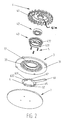
- Figure 2 is a part exploded view of the first embodiment of the present invention;
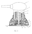
- Figure 3 is a part cross-sectional view of the first embodiment of the present invention with the coupling-decoupling element located in the first position;
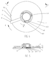
- Figure 4 is a sectional view taken along line A-A in Figure 3;
- Figure 5 is a sectional view taken along line B-B in Figure 4;
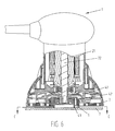
- Figure 6 is a part cross-sectional view of the first embodiment of the present invention with the coupling-decoupling element located in the second position;
- Figure 7 is a sectional view taken along line C-C in Figure 6;
- Figure 8 is a sectional view taken along line D-D in Figure 7;
- Figure 9 is a sectional view taken along line C-C in Figure 6;
- Figure 10 is a sectional blown-up view in Figure 9;
- Figure 11 is a part cross-section view of a second embodiment of the present invention with the coupling-decoupling element located in the first position;
- Figure 12 is a part cross-sectional view of the second embodiment of the present invention with the coupling-decoupling element located in the second position;
- Figure 13 is a part cross-sectional view of a third embodiment of the present invention with the coupling-decoupling element located in the first position;
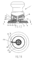
- Figure 14 is a sectional view taken along line G-G in Figure 13;
- Figure 15 is a part cross-sectional view of the third embodiment of the present invention with the coupling-decoupling element located in the second position; and
- Figure 16 is a sectional view taken along line H-H in Figure 15.
- As shown in Figure 1 and 2, a first embodiment of a sanding tool of the present invention comprises a
housing 1 and adrive unit 2 mounted in thehousing 1. Thedrive unit 2 comprises amotor 21 which drives arotary drive shaft 22. Aneccentric device 4 is mounted eccentrically on thedrive unit 2. A sandingshoe 7 is fastened axially to theeccentric device 4 at the base of thehousing 1. The sanding tool further comprises a restrainingelement 3 flexibly mounted on thehousing 1. - A coupling-
decoupling element 6 is axially disposed between the restrainingelement 3 and the sandingshoe 7. The coupling-decoupling element 6 is selectively connected to the restrainingelement 3 and movably connected to the sandingshoe 7 between a first position in which the restrainingelement 3 is decoupled from the sandingshoe 7 and a second position in which the restrainingelement 3 is coupled to the sandingshoe 7. - In the first embodiment, the restraining
element 3 is substantially annular and comprises anexterior connecting part 31 flexibly fastened to thehousing 1 by bolts and an interior restrainingpart 33 by which the restrainingelement 3 is selectively connected to the coupling-decoupling element 6. Between theexterior connecting part 31 and the interior restrainingpart 33 is an intermediateelastic part 32. - The
eccentric device 4 comprises afan 41 with aneccentric hub 41a on which is radially mounted abearing 42. A bearingsleeve 43 is mounted radially on thebearing 42. Theeccentric hub 41 a is mounted eccentrically on thedrive shaft 22 and thebearing 42 andfan 41 are fastened to thedrive shaft 22 by bolts. The sandingshoe 7 at the base of thehousing 1 is fastened to the bearingsleeve 43 by bolts. The bearingsleeve 43 has threeaxial containment slots 432 substantially equidistantly positioned substantially on its perimeter and a plurality of axial locatingcolumns 431. A first end of each of a plurality ofsprings 5 abuts against the coupling-decoupling element 6 and a second end opposite to the first end abuts against the bearingsleeve 43 in theaxial containment slot 432. - The coupling-
decoupling element 6 comprises a mulit-faceted substantially annular main body with afirst contact surface 62 and asecond contact surface 63. Thefirst contact surface 62 engages the first end of eachspring 5 and is selectively connected to the interior restrainingpart 33. Thesecond contact surface 63 engages the sandingshoe 7. Extending partially circumferentially along thesecond contact surface 63 are threecurved protrusions 631 each of which is contiguous with afirst ramp 632. - The coupling-
decoupling element 6 has three curved cut-awayportions 65 at substantially equal intervals on its inner wall. Each of the curved cut-awayportions 65 comprises a first innerradial surface 651 opposite to a second inner radial surface 652 (as shown in Figure 4) and engages arespective locating column 431 to prevent the coupling-decoupling element 6 from rotating. - The coupling-
decoupling element 6 further comprises a radially outwardly extendingoperating arm 61. The sandingshoe 7 has abracket 71 engaging theoperating arm 61 to prevent the coupling-decoupling element 6 from rotating. Thebracket 71 comprises a first exteriorradial surface 711 and a second exteriorradial surface 712. The sandingshoe 7 has at least onecurved recess 72 engaging thecurved protrusion 631 and contiguous with asecond ramp 73. Thefirst ramp 632 can move along thesecond ramp 73. - In Figures 3 to 5, the coupling-
decoupling element 6 is shown in the first position in which theoperating arm 61 engages the first exteriorradial surface 711 to prevent the coupling-decoupling element 6 from rotating in direction E. Simultaneously the locatingcolumn 431 engages the first innerradial surface 651 to prevent the coupling-decoupling element 6 from rotating in direction F. With thecurved protrusion 631 entered into thecurved recess 72, a clearance h (about 0.3-0.8 mm) is present between thefirst contact surface 62 and the interior restrainingpart 33 such that when themotor 21 rotates thedrive shaft 22, thefan 41 and bearingsleeve 43 will be driven to rotate eccentrically relative to thedrive shaft 22. The sandingshoe 7 will rotate unrestrained with the bearingsleeve 43 and the sanding tool is free to perform random orbital movement. - The
operating arm 61 can be moved from the first position to the second position by elevating theoperating arm 61 to compress thesprings 5 and then turning theoperating arm 61 in a substantially horizontal plane. Thecutaway portion 65 moves relative to the locatingcolumn 431, thefirst ramp 632 moves along thesecond ramp 73 and the coupling-decoupling element 6 rotates in direction E. When the locatingcolumn 431 contacts the second innerradial surface 652 to prevent the coupling-decoupling element 6 from rotating in direction F', the coupling-decoupling element 6 is in the second position and theoperating arm 61 contacts the second exteriorradial surface 712 to prevent the coupling-decoupling element 6 from rotating in direction E'. Thecurved protrusion 631 departs thecurved recess 72 to close the clearance h so that thefirst contact surface 62 is connected to the interior restrainingpart 33. The sandingshoe 7 is therefore coupled to the restrainingelement 3 by the coupling-decoupling element 6. When themotor 21 actuates thedrive shaft 22 to rotate, the restraining force of the restrainingpart 33 prevents the sandingshoe 7 from rotating eccentrically relative to thedrive shaft 22 and the sanding tool is restrained to perform regular orbital movement. - In a second embodiment shown in Figures 10 to 12, the features are largely the same as the first embodiment described above but with the following differences. A restraining element 3a comprises at the top a substantially annular connecting
part 31a for flexible connection to thehousing 1, at the bottom a substantially annular restrainingpart 33a and between the connectingpart 31a and the restrainingpart 33a anelastic part 32a being a plurality of flexibleaxial columns 321a. Theflexible columns 321a pass throughholes 311a in the periphery of the connectingpart 31a to the restrainingpart 33a. Theflexible columns 321a are fastened to the restrainingpart 33a by bolts. A plurality ofteeth 332a are formed on the innercircumferential underside 311a of the restrainingpart 33a. The coupling-decoupling element 6a is cross-shaped and itsfirst contact surface 62a is selectively engageable with theteeth 332a. - The sanding tool has an
operating arm 61 a comprising anoperating handle 612a connected perpendicularly to a connectingrod 66a terminating at each end in an eccentric supportingtip 663a. The supportingtips 663a are rollingly disposed on the sandingshoe 7a. The connectingrod 66a engages the coupling-decoupling element 6a and comprises afirst contact face 661 a and asecond contact face 662a. - The sanding
shoe 7a has on its upper face aradial containment groove 75a for containing theoperating handle 612a. Thebearing sleeve 43a of theeccentric device 4 hascontainment slots 433a for containing the coupling-decoupling element 6a. - As shown in Figure 11, when the coupling-decoupling element 6a is located in the first position, the
first contact face 661a of the connectingrod 66a is connected to thesecond contact surface 63a of the coupling-decoupling element 6a. In this position, thefirst contact surface 62a is disengaged from theteeth 332a of the restrainingpart 33a so that the sanding tool is free to perform random orbital movement. - As shown in Figure 12, when the coupling-decoupling element 6a is moved into the second position by rotating
operating handle 612a in a substantially vertical plane, thesecond contact face 662a of the connectingrod 66a is connected to thesecond contact surface 63a of the coupling-decoupling element 6a. In this position, thefirst contact surface 62a is engaged with theteeth 332a thereby coupling the restraining element 3a to the sandingshoe 7a to restrain the sandingshoe 7a to perform regular orbital movement. - In a third embodiment shown in Figure 13 to 16, the features are largely the same as the second embodiment described above but with the following differences. The
bearing sleeve 43b has aradial containment slot 434b for selective containment of the coupling-decoupling element 6b. The coupling-decoupling element 6b has a locatingmember 68b with aterminal grip 67b and aspring 5b disposed between the locatingmember 68b and aninner wall 81b of the housing 1b. The housing 1b has aradial projection 8b selectively engaging thegrip 67b. The restrainingpart 33b has acontainment slot 333b in which the coupling-decoupling element 6b is slidably received. - As shown in Figure 13 to 14, when the coupling-decoupling element 6a is in the first position, the
projection 8b is engaged with thegrip 67b and thespring 5b is compressed. This separates the coupling-decoupling element 6b from thecontainment slot 434b so that the restrainingelement 3b is decoupled from the sandingshoe 7b. In this circumstance, the sanding tool is free to perform random orbital movement. - As shown in Figure 15 to 16, when the coupling-decoupling element 6a is in the second position, the
projection 8b disengages thegrip 67b under the force of thespring 5b and the coupling-decoupling element 6b is urged into thecontainment slot 434b. The couples the restrainingelement 3b with the sandingshoe 7b to prevent the sandingshoe 7b from rotating with thebearing sleeve 43b. In this circumstance, the sanding tool is restrained to perform regular orbital movement.
Claims (18)
- A sanding tool comprising
a housing (1,1b);
a drive unit (2) mounted in the housing (1,1b) and having a rotary drive shaft (22);
an eccentric device (4,4a,4b) mounted eccentrically on the drive shaft (22);
a sanding shoe (7,7a,7b) mounted on the eccentric device (4,4a,4b) at the base of the housing (1,1b);
a restraining element (3,3a,3b) flexibly mounted on the housing (1,1b); and
a coupling-decoupling element (6,6a,6b) movable relative to the housing (1,1b) between a first position wherein the restraining element (3,3a,3b) is decoupled from the sanding shoe (7,7a,7b) so that the sanding shoe (7,7a,7b) is free to rotate eccentrically relative to the drive shaft (22) and a second position wherein the restraining element (3,3a,3b) is coupled to the sanding shoe (7,7a,7b) so that the sanding shoe (7,7a,7b) cannot rotate eccentrically relative to the drive shaft (22). - A sanding tool as claimed in claim 1, wherein the restraining element (3,3a,3b) comprises a connecting part (31,31a,31b) for connection to the housing, an elastic part (32,32a,32b) and a restraining part (33,33a,33b).
- A sanding tool as claimed in claim 1 or 2, wherein the coupling-decoupling element (6,6a,6b) is disposed axially between the restraining element (3,3a,3b) and the sanding shoe (7,7a,7b).
- A sanding tool as claimed in claim 3, wherein the coupling-decoupling clement (6,6a) is movably connected to the sanding shoe (7,7a), wherein in the first position the coupling-decoupling element (6,6a) is disconnected from the restraining element (3,3a) and in the second position the coupling-decoupling element (6,6a) is connected to the restraining clement (3,3a).
- A sanding tool as claimed in claim 3, wherein the coupling-decoupling element (6b) is movably connected to the restraining element (3b), wherein in the first position the coupling-decoupling element (6b) is disconnected from the sanding shoe (7b) and in the second position the coupling-decoupling element (6b) is connected to the sanding shoe (7b).
- A sanding tool as claimed in claim 3, wherein in the first position the coupling-decoupling element (6) is synchronously disconnected from the restraining element (3) and the sanding shoe (7) and in the second position the coupling-decoupling element (6) is synchronously connected to the restraining element (3) and the sanding shoe (7).
- A sanding tool as claimed in claim 2, wherein the coupling-decoupling element (6) is disposed between the housing (1) and the restraining element (3) and in the first position the coupling-decoupling element (6) is synchronously disconnected from the restraining element (3) and the sanding shoe (7) and in the second position the coupling-decoupling element (6) is synchronously connected with the restraining element (6) and the sanding shoe (7).
- A sanding tool as claimed in claim 4, wherein the coupling-decoupling element (6,6a) comprises:a first contact surface (62,62a) anda second contact surface (63,63a)wherein in the first position the first contact surface (62,62a) is disconnected from the restraining part (33,33a) and in the second position the first contact surface (62,62a) is connected to the restraining part (33,33a).
- A sanding tool as claimed in claim 8, wherein the coupling-decoupling element (6) rotates relative to the sanding shoe (7) between the first position and the second position.
- A sanding tool as claimed in claim 9, wherein the coupling-decoupling element (6) comprises an operating arm (61) and the sanding shoe (7) has at least one bracket (71 for engaging the operating arm (61) to prevent the coupling-decoupling element (6) from rotating.
- A sanding tool as claimed in claim 9 or 10, wherein the second contact surface (63) engages the sanding shoe (7) and has at least one curved protrusion (631) contiguous with a first ramp (632), wherein the sanding shoe (7) has at least one curved recess (72) contiguous with a second ramp (73) for engaging the curved protrusion (631) and the first ramp (632) respectively and wherein in the first position the curved protrusion (631) engages the curved recess (72) and the first contact surface (62) is disconnected from the restraining part (33) and wherein in the second position the curved protrusion (631) disengages the curved recess (72) and the first contact surface (62) is connected to the restraining part (33).
- A sanding tool as claimed in claim 11, wherein the eccentric device (4) has a plurality of axial containment slots (432) each containing an elastic element (5) between the coupling-decoupling element (6) and the end of the containment slot (432).
- A sanding tool as claimed in claim 11 or 12, wherein the eccentric device (4) has a plurality of axial locating columns (431) and the coupling-decoupling element (6) has a plurality of cut away portions (65), wherein each cut-away portion (65) engages a respective locating column (431) to prevent the coupling-decoupling element (6) from rotating.
- A sanding tool as claimed in claim 8 further comprising:an operating arm (61a) engaged with the coupling-decoupling element (6) and having an operating handle (612a) connected perpendicularly to a connecting rod (66a) terminating at each end in an eccentric supporting tip (663a), wherein each supporting tip is rollingly disposed on the sanding shoe (7a) and the connecting rod (66a) has a first contact face (661a) and a second contact face (662a).
- A sanding tool as claimed in claim 14, wherein in the first position the first contact face (661 a) is connected to the second contact surface (63a) and the first contact surface (62a) is disconnected from the restraining part (33a) and wherein in the second position the second contact face (662a) is connected to the second contact surface (63a) and the first contact surface (62a) is connected to the restraining part (33a).
- A sanding tool as claimed in claim 15, wherein the eccentric device (4a) has a containment slot (433a) for containing the coupling-decoupling element (6a).
- A sanding tool as claimed in claim 5, wherein the restraining part (33b) has a containment slot (333b) and the coupling-decoupling element (6b) is slidably received in the containment slot (333b), the eccentric device (4) has a containment slot (434b) for containing the coupling-decoupling element (6b), wherein in the first position the coupling-decoupling element (6b) is separated from the containment slot (434b) and the restraining element (3b) is decoupled from the sanding shoe (7b) and in the second position the coupling-decoupling element (6b) is received in the containment slot (434b) and the restraining element (3b) is coupled to the sanding shoe (7b).
- A sanding tool as claimed in claim 1, wherein the eccentric device (4,4a,4b) comprises:a fan (41) eccentrically mounted on the drive shaft (22) anda bearing sleeve (43,43a,43b) on which is mounted the sanding shoe (7,7a,7b) at the base of the housing (1).
Applications Claiming Priority (1)
| Application Number | Priority Date | Filing Date | Title |
|---|---|---|---|
| CN 200510041161 CN1724216A (en) | 2005-07-21 | 2005-07-21 | Multifunctional electric abrasive finishing machine |
Publications (1)
| Publication Number | Publication Date |
|---|---|
| EP1745887A1 true EP1745887A1 (en) | 2007-01-24 |
Family
ID=35923916
Family Applications (1)
| Application Number | Title | Priority Date | Filing Date |
|---|---|---|---|
| EP06253605A Withdrawn EP1745887A1 (en) | 2005-07-21 | 2006-07-10 | Sanding tool |
Country Status (2)
| Country | Link |
|---|---|
| EP (1) | EP1745887A1 (en) |
| CN (1) | CN1724216A (en) |
Cited By (7)
| Publication number | Priority date | Publication date | Assignee | Title |
|---|---|---|---|---|
| EP2366495A1 (en) * | 2010-03-19 | 2011-09-21 | Festool GmbH | Manually operated machine tool with an eccentric drive and a latch |
| EP2366493A1 (en) * | 2010-03-19 | 2011-09-21 | Festool GmbH | Manually operated machine tool with an eccentric drive comprising a rotation angle manager |
| CN111906657A (en) * | 2019-05-07 | 2020-11-10 | 盖多·瓦伦蒂尼 | Hand-held power tool for sanding or polishing a workpiece |
| CN111958431A (en) * | 2018-03-21 | 2020-11-20 | 盖多·瓦伦蒂尼 | Hand-held machine tool for sanding or polishing workpieces and for carrying out two working movements |
| CN112171466A (en) * | 2020-06-28 | 2021-01-05 | 南京久驰机电实业有限公司 | A multifunctional sanding machine |
| CN114888665A (en) * | 2022-05-13 | 2022-08-12 | 深圳市威纳盛五金工艺品有限公司 | Adjustable metal handicraft spherical part grinding device |
| CN117961688A (en) * | 2024-04-02 | 2024-05-03 | 江苏三晶半导体材料有限公司 | Polishing device for semiconductor production |
Families Citing this family (6)
| Publication number | Priority date | Publication date | Assignee | Title |
|---|---|---|---|---|
| CN101186027B (en) * | 2007-12-21 | 2013-03-27 | 南京德朔实业有限公司 | Sanding tool |
| CN101633143B (en) * | 2008-07-25 | 2012-10-24 | 苏州宝时得电动工具有限公司 | Hand-held tool and application method thereof |
| CN103100954B (en) * | 2011-11-09 | 2015-10-28 | 大亚人造板集团有限公司 | Sander braking protection device and sander |
| CN105983891B (en) * | 2015-02-16 | 2018-04-20 | 苏州宝时得电动工具有限公司 | Multifunction sander |
| CN106392835B (en) * | 2015-07-30 | 2019-03-08 | 南京德朔实业有限公司 | sander |
| CN106493623B (en) * | 2015-09-04 | 2019-08-06 | 南京德朔实业有限公司 | Polishing class tool and sander |
Citations (5)
| Publication number | Priority date | Publication date | Assignee | Title |
|---|---|---|---|---|
| EP0525328A1 (en) | 1991-06-05 | 1993-02-03 | Robert Bosch Gmbh | Grinder with eccentric |
| US6132300A (en) | 1994-07-26 | 2000-10-17 | Black & Decker Inc. | Dual function oscillating tool |
| WO2002062526A1 (en) * | 2001-02-03 | 2002-08-15 | Robert Bosch Gmbh | Hand-held machine tool for grinding, polishing or the like |
| US6739493B2 (en) | 2002-07-19 | 2004-05-25 | Esec Trading Sa | Device with an electrode for the formation of a ball at the end of a wire |
| JP2005022000A (en) * | 2003-06-30 | 2005-01-27 | Compact Tool Co Ltd | Dual-mode sander |
-
2005
- 2005-07-21 CN CN 200510041161 patent/CN1724216A/en active Pending
-
2006
- 2006-07-10 EP EP06253605A patent/EP1745887A1/en not_active Withdrawn
Patent Citations (5)
| Publication number | Priority date | Publication date | Assignee | Title |
|---|---|---|---|---|
| EP0525328A1 (en) | 1991-06-05 | 1993-02-03 | Robert Bosch Gmbh | Grinder with eccentric |
| US6132300A (en) | 1994-07-26 | 2000-10-17 | Black & Decker Inc. | Dual function oscillating tool |
| WO2002062526A1 (en) * | 2001-02-03 | 2002-08-15 | Robert Bosch Gmbh | Hand-held machine tool for grinding, polishing or the like |
| US6739493B2 (en) | 2002-07-19 | 2004-05-25 | Esec Trading Sa | Device with an electrode for the formation of a ball at the end of a wire |
| JP2005022000A (en) * | 2003-06-30 | 2005-01-27 | Compact Tool Co Ltd | Dual-mode sander |
Non-Patent Citations (1)
| Title |
|---|
| PATENT ABSTRACTS OF JAPAN vol. 2003, no. 12 5 December 2003 (2003-12-05) * |
Cited By (12)
| Publication number | Priority date | Publication date | Assignee | Title |
|---|---|---|---|---|
| EP2366495A1 (en) * | 2010-03-19 | 2011-09-21 | Festool GmbH | Manually operated machine tool with an eccentric drive and a latch |
| EP2366493A1 (en) * | 2010-03-19 | 2011-09-21 | Festool GmbH | Manually operated machine tool with an eccentric drive comprising a rotation angle manager |
| DE102010012021B3 (en) * | 2010-03-19 | 2011-09-22 | Festool Gmbh | Hand machine tool with an eccentric gear and a lock |
| CN111958431A (en) * | 2018-03-21 | 2020-11-20 | 盖多·瓦伦蒂尼 | Hand-held machine tool for sanding or polishing workpieces and for carrying out two working movements |
| CN111906657A (en) * | 2019-05-07 | 2020-11-10 | 盖多·瓦伦蒂尼 | Hand-held power tool for sanding or polishing a workpiece |
| EP3736084A1 (en) * | 2019-05-07 | 2020-11-11 | Guido Valentini | Hand-held power tool for sanding or polishing a workpiece |
| CN111906657B (en) * | 2019-05-07 | 2022-08-30 | 盖多·瓦伦蒂尼 | Hand-held power tool for sanding or polishing a workpiece |
| US12005542B2 (en) | 2019-05-07 | 2024-06-11 | Guido Valentini | Hand-held power tool for sending or polishing a workpiece |
| CN112171466A (en) * | 2020-06-28 | 2021-01-05 | 南京久驰机电实业有限公司 | A multifunctional sanding machine |
| CN114888665A (en) * | 2022-05-13 | 2022-08-12 | 深圳市威纳盛五金工艺品有限公司 | Adjustable metal handicraft spherical part grinding device |
| CN117961688A (en) * | 2024-04-02 | 2024-05-03 | 江苏三晶半导体材料有限公司 | Polishing device for semiconductor production |
| CN117961688B (en) * | 2024-04-02 | 2024-06-11 | 江苏三晶半导体材料有限公司 | Polishing device for semiconductor production |
Also Published As
| Publication number | Publication date |
|---|---|
| CN1724216A (en) | 2006-01-25 |
Similar Documents
| Publication | Publication Date | Title |
|---|---|---|
| US2794303A (en) | Power-driven hand tool | |
| US5947804A (en) | Adjustable eccentricity orbital tool | |
| CN101516571B (en) | Multifunction sander | |
| EP0123722B1 (en) | Clutch assembly for sanding head | |
| US6241590B1 (en) | External abrasive machine | |
| US5441450A (en) | Power tool having means to switch from oscillatory movement to rotary movement | |
| GB2337013A (en) | Hand tool having easily separable tool holders | |
| JPH11508833A (en) | Hand-held electric grinder | |
| JP2005523829A (en) | Installation tool with a disk-shaped boss that can be rotated and a quick clamping system | |
| CA2347638A1 (en) | Portable single-point beveling tool | |
| JP4215877B2 (en) | Tool | |
| EP0636454B1 (en) | Device for manual assembly and removal of working discs in manual tools for machining surfaces | |
| US6350187B2 (en) | Abrasive machine | |
| AU728799B2 (en) | Internal abrasive machine | |
| EP0379009A2 (en) | Quick-coupling device particularly for coupling rotating tools to a driving unit | |
| EP1714739A1 (en) | Hand guided sanding tool | |
| JP3498999B2 (en) | Multifunctional polishing equipment | |
| US6435954B1 (en) | Abrasive machine for machining a flange on a work piece | |
| CN223169622U (en) | Manual grinder | |
| JP3498998B2 (en) | Multifunctional polishing equipment | |
| WO2000040369A1 (en) | An abrasive machine for machining a surface of a cylindrical work piece | |
| CN110919092A (en) | An easy-to-move saw blade grinder | |
| MXPA00000093A (en) | Internal abrasive machine | |
| RO112417B1 (en) | Tool grinding machine for home use |
Legal Events
| Date | Code | Title | Description |
|---|---|---|---|
| PUAI | Public reference made under article 153(3) epc to a published international application that has entered the european phase |
Free format text: ORIGINAL CODE: 0009012 |
|
| AK | Designated contracting states |
Kind code of ref document: A1 Designated state(s): AT BE BG CH CY CZ DE DK EE ES FI FR GB GR HU IE IS IT LI LT LU LV MC NL PL PT RO SE SI SK TR |
|
| AX | Request for extension of the european patent |
Extension state: AL BA HR MK YU |
|
| 17P | Request for examination filed |
Effective date: 20070619 |
|
| AKX | Designation fees paid |
Designated state(s): DE FR GB |
|
| GRAP | Despatch of communication of intention to grant a patent |
Free format text: ORIGINAL CODE: EPIDOSNIGR1 |
|
| STAA | Information on the status of an ep patent application or granted ep patent |
Free format text: STATUS: THE APPLICATION IS DEEMED TO BE WITHDRAWN |
|
| 18D | Application deemed to be withdrawn |
Effective date: 20080216 |