EP1745863A2 - Doctor blade coated with polymeric material and coating method - Google Patents
Doctor blade coated with polymeric material and coating method Download PDFInfo
- Publication number
- EP1745863A2 EP1745863A2 EP20060013914 EP06013914A EP1745863A2 EP 1745863 A2 EP1745863 A2 EP 1745863A2 EP 20060013914 EP20060013914 EP 20060013914 EP 06013914 A EP06013914 A EP 06013914A EP 1745863 A2 EP1745863 A2 EP 1745863A2
- Authority
- EP
- European Patent Office
- Prior art keywords
- doctor blade
- layer
- polymeric material
- support
- coating
- Prior art date
- Legal status (The legal status is an assumption and is not a legal conclusion. Google has not performed a legal analysis and makes no representation as to the accuracy of the status listed.)
- Withdrawn
Links
- 239000000463 material Substances 0.000 title claims abstract description 37
- 238000000576 coating method Methods 0.000 title claims abstract description 15
- 229910052751 metal Inorganic materials 0.000 claims abstract description 40
- 239000002184 metal Substances 0.000 claims abstract description 40
- 229920006362 Teflon® Polymers 0.000 claims abstract description 22
- 239000004809 Teflon Substances 0.000 claims abstract description 18
- 238000000034 method Methods 0.000 claims abstract description 14
- 239000011248 coating agent Substances 0.000 claims abstract description 13
- 229910000831 Steel Inorganic materials 0.000 claims abstract description 7
- 239000010959 steel Substances 0.000 claims abstract description 7
- 239000010410 layer Substances 0.000 claims description 52
- 239000011247 coating layer Substances 0.000 claims description 20
- 238000007639 printing Methods 0.000 claims description 20
- 239000011343 solid material Substances 0.000 claims description 11
- 230000001050 lubricating effect Effects 0.000 claims description 10
- 150000001247 metal acetylides Chemical class 0.000 claims description 4
- OKTJSMMVPCPJKN-UHFFFAOYSA-N Carbon Chemical compound [C] OKTJSMMVPCPJKN-UHFFFAOYSA-N 0.000 claims description 3
- 238000007598 dipping method Methods 0.000 claims description 3
- 238000005507 spraying Methods 0.000 claims description 3
- 229910000906 Bronze Inorganic materials 0.000 claims description 2
- ZOKXTWBITQBERF-UHFFFAOYSA-N Molybdenum Chemical compound [Mo] ZOKXTWBITQBERF-UHFFFAOYSA-N 0.000 claims description 2
- 239000004411 aluminium Substances 0.000 claims description 2
- 229910052782 aluminium Inorganic materials 0.000 claims description 2
- XAGFODPZIPBFFR-UHFFFAOYSA-N aluminium Chemical compound [Al] XAGFODPZIPBFFR-UHFFFAOYSA-N 0.000 claims description 2
- 239000010974 bronze Substances 0.000 claims description 2
- 239000010941 cobalt Substances 0.000 claims description 2
- 229910017052 cobalt Inorganic materials 0.000 claims description 2
- GUTLYIVDDKVIGB-UHFFFAOYSA-N cobalt atom Chemical compound [Co] GUTLYIVDDKVIGB-UHFFFAOYSA-N 0.000 claims description 2
- KUNSUQLRTQLHQQ-UHFFFAOYSA-N copper tin Chemical compound [Cu].[Sn] KUNSUQLRTQLHQQ-UHFFFAOYSA-N 0.000 claims description 2
- 229910002804 graphite Inorganic materials 0.000 claims description 2
- 239000010439 graphite Substances 0.000 claims description 2
- 229910052750 molybdenum Inorganic materials 0.000 claims description 2
- 239000011733 molybdenum Substances 0.000 claims description 2
- PTISTKLWEJDJID-UHFFFAOYSA-N sulfanylidenemolybdenum Chemical compound [Mo]=S PTISTKLWEJDJID-UHFFFAOYSA-N 0.000 claims description 2
- PXHVJJICTQNCMI-UHFFFAOYSA-N Nickel Chemical compound [Ni] PXHVJJICTQNCMI-UHFFFAOYSA-N 0.000 description 8
- 239000000126 substance Substances 0.000 description 5
- 229910052759 nickel Inorganic materials 0.000 description 4
- 238000007790 scraping Methods 0.000 description 4
- VYZAMTAEIAYCRO-UHFFFAOYSA-N Chromium Chemical compound [Cr] VYZAMTAEIAYCRO-UHFFFAOYSA-N 0.000 description 3
- 229910052804 chromium Inorganic materials 0.000 description 3
- 239000011651 chromium Substances 0.000 description 3
- 238000000151 deposition Methods 0.000 description 3
- 239000000314 lubricant Substances 0.000 description 3
- 239000000203 mixture Substances 0.000 description 3
- 239000002245 particle Substances 0.000 description 3
- 239000000843 powder Substances 0.000 description 3
- 229910010293 ceramic material Inorganic materials 0.000 description 2
- 230000008021 deposition Effects 0.000 description 2
- 239000013013 elastic material Substances 0.000 description 2
- 239000011888 foil Substances 0.000 description 2
- 239000007788 liquid Substances 0.000 description 2
- 239000004033 plastic Substances 0.000 description 2
- 238000007747 plating Methods 0.000 description 2
- 239000011347 resin Substances 0.000 description 2
- 229920005989 resin Polymers 0.000 description 2
- 238000005299 abrasion Methods 0.000 description 1
- 239000000853 adhesive Substances 0.000 description 1
- 230000001070 adhesive effect Effects 0.000 description 1
- 229910045601 alloy Inorganic materials 0.000 description 1
- 239000000956 alloy Substances 0.000 description 1
- 230000015572 biosynthetic process Effects 0.000 description 1
- 229910052799 carbon Inorganic materials 0.000 description 1
- 239000003795 chemical substances by application Substances 0.000 description 1
- 238000004140 cleaning Methods 0.000 description 1
- 239000010960 cold rolled steel Substances 0.000 description 1
- 238000005260 corrosion Methods 0.000 description 1
- 230000007797 corrosion Effects 0.000 description 1
- 230000001419 dependent effect Effects 0.000 description 1
- 239000000428 dust Substances 0.000 description 1
- 230000000694 effects Effects 0.000 description 1
- 239000000835 fiber Substances 0.000 description 1
- 238000005246 galvanizing Methods 0.000 description 1
- 238000007644 letterpress printing Methods 0.000 description 1
- 238000004519 manufacturing process Methods 0.000 description 1
- 229910000734 martensite Inorganic materials 0.000 description 1
- 229910044991 metal oxide Inorganic materials 0.000 description 1
- 150000004706 metal oxides Chemical class 0.000 description 1
- 150000002739 metals Chemical class 0.000 description 1
- 238000012986 modification Methods 0.000 description 1
- 230000004048 modification Effects 0.000 description 1
- 150000004767 nitrides Chemical class 0.000 description 1
- 229920000620 organic polymer Polymers 0.000 description 1
- 239000006072 paste Substances 0.000 description 1
- 238000007750 plasma spraying Methods 0.000 description 1
- 229920000642 polymer Polymers 0.000 description 1
- 238000005096 rolling process Methods 0.000 description 1
- 238000007650 screen-printing Methods 0.000 description 1
- 238000003892 spreading Methods 0.000 description 1
- 229920002994 synthetic fiber Polymers 0.000 description 1
Images


Classifications
-
- B—PERFORMING OPERATIONS; TRANSPORTING
- B41—PRINTING; LINING MACHINES; TYPEWRITERS; STAMPS
- B41F—PRINTING MACHINES OR PRESSES
- B41F9/00—Rotary intaglio printing presses
- B41F9/06—Details
- B41F9/08—Wiping mechanisms
- B41F9/10—Doctors, scrapers, or like devices
- B41F9/1072—Blade construction
-
- B—PERFORMING OPERATIONS; TRANSPORTING
- B08—CLEANING
- B08B—CLEANING IN GENERAL; PREVENTION OF FOULING IN GENERAL
- B08B1/00—Cleaning by methods involving the use of tools
- B08B1/10—Cleaning by methods involving the use of tools characterised by the type of cleaning tool
- B08B1/16—Rigid blades, e.g. scrapers; Flexible blades, e.g. wipers
- B08B1/165—Scrapers
-
- B—PERFORMING OPERATIONS; TRANSPORTING
- B41—PRINTING; LINING MACHINES; TYPEWRITERS; STAMPS
- B41N—PRINTING PLATES OR FOILS; MATERIALS FOR SURFACES USED IN PRINTING MACHINES FOR PRINTING, INKING, DAMPING, OR THE LIKE; PREPARING SUCH SURFACES FOR USE AND CONSERVING THEM
- B41N10/00—Blankets or like coverings; Coverings for wipers for intaglio printing
- B41N10/005—Coverings for wipers
-
- D—TEXTILES; PAPER
- D21—PAPER-MAKING; PRODUCTION OF CELLULOSE
- D21G—CALENDERS; ACCESSORIES FOR PAPER-MAKING MACHINES
- D21G3/00—Doctors
- D21G3/005—Doctor knifes
-
- Y—GENERAL TAGGING OF NEW TECHNOLOGICAL DEVELOPMENTS; GENERAL TAGGING OF CROSS-SECTIONAL TECHNOLOGIES SPANNING OVER SEVERAL SECTIONS OF THE IPC; TECHNICAL SUBJECTS COVERED BY FORMER USPC CROSS-REFERENCE ART COLLECTIONS [XRACs] AND DIGESTS
- Y10—TECHNICAL SUBJECTS COVERED BY FORMER USPC
- Y10T—TECHNICAL SUBJECTS COVERED BY FORMER US CLASSIFICATION
- Y10T428/00—Stock material or miscellaneous articles
- Y10T428/24—Structurally defined web or sheet [e.g., overall dimension, etc.]
- Y10T428/24355—Continuous and nonuniform or irregular surface on layer or component [e.g., roofing, etc.]
-
- Y—GENERAL TAGGING OF NEW TECHNOLOGICAL DEVELOPMENTS; GENERAL TAGGING OF CROSS-SECTIONAL TECHNOLOGIES SPANNING OVER SEVERAL SECTIONS OF THE IPC; TECHNICAL SUBJECTS COVERED BY FORMER USPC CROSS-REFERENCE ART COLLECTIONS [XRACs] AND DIGESTS
- Y10—TECHNICAL SUBJECTS COVERED BY FORMER USPC
- Y10T—TECHNICAL SUBJECTS COVERED BY FORMER US CLASSIFICATION
- Y10T428/00—Stock material or miscellaneous articles
- Y10T428/24—Structurally defined web or sheet [e.g., overall dimension, etc.]
- Y10T428/24942—Structurally defined web or sheet [e.g., overall dimension, etc.] including components having same physical characteristic in differing degree
- Y10T428/2495—Thickness [relative or absolute]
-
- Y—GENERAL TAGGING OF NEW TECHNOLOGICAL DEVELOPMENTS; GENERAL TAGGING OF CROSS-SECTIONAL TECHNOLOGIES SPANNING OVER SEVERAL SECTIONS OF THE IPC; TECHNICAL SUBJECTS COVERED BY FORMER USPC CROSS-REFERENCE ART COLLECTIONS [XRACs] AND DIGESTS
- Y10—TECHNICAL SUBJECTS COVERED BY FORMER USPC
- Y10T—TECHNICAL SUBJECTS COVERED BY FORMER US CLASSIFICATION
- Y10T428/00—Stock material or miscellaneous articles
- Y10T428/24—Structurally defined web or sheet [e.g., overall dimension, etc.]
- Y10T428/24942—Structurally defined web or sheet [e.g., overall dimension, etc.] including components having same physical characteristic in differing degree
- Y10T428/2495—Thickness [relative or absolute]
- Y10T428/24967—Absolute thicknesses specified
- Y10T428/24975—No layer or component greater than 5 mils thick
-
- Y—GENERAL TAGGING OF NEW TECHNOLOGICAL DEVELOPMENTS; GENERAL TAGGING OF CROSS-SECTIONAL TECHNOLOGIES SPANNING OVER SEVERAL SECTIONS OF THE IPC; TECHNICAL SUBJECTS COVERED BY FORMER USPC CROSS-REFERENCE ART COLLECTIONS [XRACs] AND DIGESTS
- Y10—TECHNICAL SUBJECTS COVERED BY FORMER USPC
- Y10T—TECHNICAL SUBJECTS COVERED BY FORMER US CLASSIFICATION
- Y10T428/00—Stock material or miscellaneous articles
- Y10T428/31504—Composite [nonstructural laminate]
- Y10T428/3154—Of fluorinated addition polymer from unsaturated monomers
- Y10T428/31544—Addition polymer is perhalogenated
-
- Y—GENERAL TAGGING OF NEW TECHNOLOGICAL DEVELOPMENTS; GENERAL TAGGING OF CROSS-SECTIONAL TECHNOLOGIES SPANNING OVER SEVERAL SECTIONS OF THE IPC; TECHNICAL SUBJECTS COVERED BY FORMER USPC CROSS-REFERENCE ART COLLECTIONS [XRACs] AND DIGESTS
- Y10—TECHNICAL SUBJECTS COVERED BY FORMER USPC
- Y10T—TECHNICAL SUBJECTS COVERED BY FORMER US CLASSIFICATION
- Y10T428/00—Stock material or miscellaneous articles
- Y10T428/31504—Composite [nonstructural laminate]
- Y10T428/31678—Of metal
Definitions
- the present invention refers to a doctor blade comprising a metal support completely coated with a polymeric material, in particular Teflon s ®, and a method of coating said support.
- Doctor blades are well-known tools and are normally used to remove from a cylindrical surface ⁇ with a finite radius (cylinder) or an infinite radius (flat surface) - a product (liquid, paste or powder) previously adhering to said surface.
- Doctor blades can therefore be used in many fields to clean the surface of cylinders used (for example) for printing, for distributing and spreading adhesives, for grinding, etc.
- doctor blades are used to distribute printing ink on a frame (such as, for example, in screen printing) or to remove excess ink from a printing cylinder (rotogravure, flexographic printing, etc.) or from a flat processed block (letterpress printing, tampography).
- a doctor blade operates in direct contact with the surface of the printing cylinder to eliminate the printing ink from the unengraved parts of said surface and the excess ink from the engraved parts of said surface; both the doctor blade and the surface of the printing cylinder are therefore subject to wear since the speed of rotation is high.
- printing cylinders are often coated with a layer of hard material (for example ceramic material or hard chromium), which can differ according to specific applications.
- hard material for example ceramic material or hard chromium
- doctor blades for printing presses currently in use mainly consist of a precision steel band, cold rolled, hardened and tempered, in which one or both of the straight edges destined to come into contact with the surface of the printing cylinder have the profile (rectangular, rounded, pre-sharpened with a foil shape or a bevel shape, etc.) considered most advantageous to meet specific requirements on a case by case basis.
- the edge of the doctor blade is coated with thin layers of metal or with chemical nickel (possibly with hard substances added) or thin layers of carbides and/or of metal nitrides or relatively thick layers of ceramic material (metal oxides) are deposited thereon through long, costly procedures.
- the doctor blade in many applications consists of an extremely high-cost stainless martensitic steel band.
- Doctor blades totally consisting of synthetic materials to improve their adhesion to the surface of the cylinder and to reduce the wear on said cylinder are also known to the art.
- the various coatings are applied with methods known to the art, amongst which are spraying, rolling, dipping, powder coating, coil coating or electrolytic deposition (for example of nickel or chromium), etc.
- US-A1-2004/0137261 describes a doctor blade of the type previously described, in which all the coating layers placed on the support (generally steel) are metallic, consisting in particular of electrodeposited nickel with various materials added.
- NL-A-9300810 describes a doctor blade wherein the coating layer generally consists of a layer of plastic material, having a smooth surface, which can be different from or coincide with an elastic material fixed beneath the plastic material.
- DE-U-20216494 describes a scraper ring (of metal or of carbon fibre) wherein the coating layer placed on the active surface consists of an elastic material chosen among the organic polymers and has a minimum thickness of 1 mm.
- US-A1-2002/0157548 describes a doctor blade wherein the coating layer placed on the support (of cold-rolled steel with specific characteristics of composition and hardness) consists of a material with low resistance to wear (preferably) chosen among the metals, or among alloys, oxides, polymers or mixtures thereof; the application methods mentioned are manifold, amongst which there are plasma spraying, galvanising, etc.
- US-A1-2005/0089706 describes a doctor blade of the type previously described, wherein the first coating layer placed on the support (of unspecified nature) is always metal (in particular, chromium plating or nickel plating) and the second layer consists of a deposition of organic resin.
- Object of the present invention is to produce a doctor blade able to overcome the abovementioned drawbacks presented by doctor blades of the prior art. This object is achieved by means of a doctor blade which has the characterising features illustrated in claim 1, produced by means of the method illustrated in claim 14.
- the doctor blade forming the subject matter of the present invention consists of a metal support coated ⁇ by means of the above mentioned method ⁇ with a coating layer of Teflon s ® with a variable thickness, possibly with a solid material added.
- Teflon s ® is a commercially available resin (containing Teflon ® with other substances added) and will not therefore be described herein.
- Teflon s ® Because of its physico-chemical characteristics, Teflon s ® proves able to adhere perfectly to the polished surface of the metal support.
- the coating layer with variable thickness consists of Teflon s ® but, without departing from the scope of the invention, this coating layer can consist of another functionally equivalent polymeric material.
- a doctor blade produced according to the invention able to operate in combination with a printing cylinder, comprises a metal support coated with a variable thickness layer of Teflon s ®, possibly with a solid material added, which comprises an ultrathin layer placed on the whole surface of the metal support of the doctor blade and a thicker layer placed over the ultrathin layer, which partially coats the surface of the doctor blade.
- the thicker layer coats one side of an edge of the doctor blade or both sides of an edge of the doctor blade or the same side of both edges of the doctor blade or both sides of both edges of the doctor blade or one side of the doctor blade or both sides of the doctor blade (figures 1a ⁇ 1f).
- the thicker layer coats at least the side of the edge of the doctor blade that works in contact with the surface of a printing cylinder and the front head part of said side.
- the thickness of the ultrathin coating layer protecting the whole surface of the doctor blade is between 0,2 and 0,5 ⁇ m, preferably 0,3 ⁇ m; the thickness of the thicker layer, where applied with the object of improving the performance of the doctor blade or of the cylinder-doctor blade assembly, is between 1 and 10 ⁇ m, preferably 5 ⁇ m.
- Figure 1 shows diagrammatically some possible embodiments of a doctor blade produced according to the invention, wherein the ultrathin coating layer 0 ( Figure 2), present on the whole surface of the metal support 3 of the doctor blade 1, has been omitted for the sake of simplicity of the graphic representation.
- edges 4 and 5 of a doctor blade 1 produced according to the invention can have the profile (rectangular, rounded, pre-sharpened with a foil or a bevel shape, etc.) considered most advantageous to meet specific requirements on a case-by-case basis.
- the metal support 3 is preferably made from a cold-rolled, hardened and tempered steel band with a polished surface having a roughness no greater than 2 ⁇ m.
- the material selected for coating of the doctor blade 1 forming the subject matter of the present invention is preferably Teflon s ®, possibly with solid material added; this choice ensures excellent adhesiveness of the coating to the polished surface of the metal support of the doctor blade.
- Coating, according to requirements, with a thicker layer 6 one side of one edge (4 or 5) of the doctor blade 1 or both sides of one edge (4 or 5) of the doctor blade 1 or the same side of both edges (4, 5) of the doctor blade 1 or both sides of both edges (4, 5) of the doctor blade 1 or one side of the doctor blade 1 or both sides of the doctor blade 1 proves advantageous since the performance of the doctor blade-cylinder assembly is appreciably improved, as detailed hereunder.
- the Applicant has verified experimentally that the formation on the metal support 3 of the coating forming the subject matter of the present invention improves the contact between doctor blade 1 and cylinder and therefore the removal from the surface of the cylinder of excess liquids or dust during the scraping process.
- the solid material possibly added to the Teflon s ® consists of metal micropowder and/or flakes and of dry lubricating material, even of metal carbides if necessary.
- the addition of solid material to the mixture advantageously serves to improve the characteristics of hardness, elasticity, resistance to the abrasion, lubricating and non-stick capability of the coating layer.
- the metal micropowders and/or flakes are, for example, aluminium, bronze, molybdenum, cobalt, etc.; they advantageously serve to remetallize any microporosities present on the surface of the cylinder during the scraping process.
- the dry lubricating material is preferably Teflon ®, or graphite, molybdenum sulphide, etc.; advantageously, these particles of dry lubricant serve to dry lubricate the cylinder.
- these particles of dry lubricant are advantageously released during the scraping process and lubricate, by interposition, the metal-to-metal contact surfaces between the doctor blade and the cylinder; they thus drastically reduce friction and, consequently, wear on the doctor blade and on the cylinder surface.
- said particles of dry lubricant which have non-stick properties, reduce the stickiness of the surface of the doctor blade and thus the undesired gathering and build-up of substances between the doctor blade and the cylinder surface.
- Metal carbides which have microabrasive properties, if added to the Teflon s ®, advantageously serve to obtain the desired microtexture of the cylinder, particularly for rotogravure printing.
- the weight of the solid material added to the Teflon s ® of the thicker layer 6 is between 10% and 40% of the overall weight of the coating layer of the metal support 3; the weight of the dry lubricating material added to the thicker layer 6 is between 5% and 30% of the overall weight of the coating layer of the metal support 3.
- the coating is advantageously conceived to have a low surface tension and to repel the majority of the products to be scraped.
- Figure 2 shows diagrammatically, enlarged, the detail highlighted in Figure 1f; in Figure 2 the edge 4 of the metal support 3 coated with the ultrathin layer 0 and with a thicker layer 6 of Teflon s ®, possibly with solid material added, which covers the front part and both sides of the edge 4 can be seen better.
- Figure 3 shows diagrammatically a front view of a doctor blade 1 placed in contact, along a line of contact indicated by 8 in Figures 3 and 4, with the surface of a printing cylinder 2.
- doctor blade 1 is carried by a doctor blade holder 7, not described herein as it is per se known and in any case it is outside the scope of the present invention.
- the thicker layer 6 consisting of Teflon s ® possibly with added material penetrates (or can penetrate) into the flaws and into the scratches present on the surface of the cylinder 2 (represented in Figure 4 by a plurality of grooves 9), improving the adhesion of the doctor blade 1 to the surface of the cylinder 2 and, consequently, the cleaning effect exerted by the doctor blade 1 on said surface.
- Figure 5 shows diagrammatically a partial side view of a printing cylinder 2 in contact with a doctor blade 1 coated on its whole surface with an ultrathin layer 0 (omitted in Figure 5 for the sake of simplicity of the graphic representation) and on both sides with a thicker layer 6 of Teflon s ®, possibly with added material.
- the metal support 3 of the doctor blade 1 and a layer 10 of a material (for example ink) which coats the surface of the cylinder 2 and which is removed by the doctor blade 1 can also be seen in Figure 5; the direction of rotation of the cylinder 2 is indicated in Figures 5 and 6 by means of the arrow 11.
- a material for example ink
- variable thickness layer for distributing a coating varying in thickness from 0,2 to 10,5 ⁇ m in a continuous manner along the surface of a metal support 3 consisting of a steel band, which comprises the following steps:
Landscapes
- Engineering & Computer Science (AREA)
- Mechanical Engineering (AREA)
- Rotary Presses (AREA)
- Paper (AREA)
- Coating Apparatus (AREA)
- Printing Plates And Materials Therefor (AREA)
- Laminated Bodies (AREA)
Abstract
- an ultrathin layer (0) which coats the whole surface of the doctor blade (1);
- a thicker layer (6) which coats one side of one edge (4, 5) of the doctor blade (1) or both sides of one edge (4, 5) of the doctor blade (1) or the same side of both edges (4, 5) of the doctor blade (1) or both sides of both edges (4, 5) or one side of the doctor blade (1) or both sides of the doctor blade (1).
Description
- The present invention refers to a doctor blade comprising a metal support completely coated with a polymeric material, in particular Teflon s ®, and a method of coating said support.
- Doctor blades are well-known tools and are normally used to remove from a cylindrical surface ― with a finite radius (cylinder) or an infinite radius (flat surface) - a product (liquid, paste or powder) previously adhering to said surface.
- Doctor blades can therefore be used in many fields to clean the surface of cylinders used (for example) for printing, for distributing and spreading adhesives, for grinding, etc.
- In many printing methods doctor blades are used to distribute printing ink on a frame (such as, for example, in screen printing) or to remove excess ink from a printing cylinder (rotogravure, flexographic printing, etc.) or from a flat processed block (letterpress printing, tampography).
- With particular reference to printing presses, a doctor blade operates in direct contact with the surface of the printing cylinder to eliminate the printing ink from the unengraved parts of said surface and the excess ink from the engraved parts of said surface; both the doctor blade and the surface of the printing cylinder are therefore subject to wear since the speed of rotation is high.
- Consequently, printing cylinders are often coated with a layer of hard material (for example ceramic material or hard chromium), which can differ according to specific applications.
- The doctor blades for printing presses currently in use mainly consist of a precision steel band, cold rolled, hardened and tempered, in which one or both of the straight edges destined to come into contact with the surface of the printing cylinder have the profile (rectangular, rounded, pre-sharpened with a foil shape or a bevel shape, etc.) considered most advantageous to meet specific requirements on a case by case basis.
- To improve the resistance to wear of the edge of the doctor blade without (excessively) damaging the surface of the cylinder, the edge of the doctor blade is coated with thin layers of metal or with chemical nickel (possibly with hard substances added) or thin layers of carbides and/or of metal nitrides or relatively thick layers of ceramic material (metal oxides) are deposited thereon through long, costly procedures.
- In order to avoid corrosion phenomena, the doctor blade in many applications consists of an extremely high-cost stainless martensitic steel band.
- Doctor blades totally consisting of synthetic materials to improve their adhesion to the surface of the cylinder and to reduce the wear on said cylinder are also known to the art.
- The various coatings are applied with methods known to the art, amongst which are spraying, rolling, dipping, powder coating, coil coating or electrolytic deposition (for example of nickel or chromium), etc.
- Purely by way of non-limiting example some documents having as their subject matter coated doctor blades are cited.
-
US-A1-2004/0137261 describes a doctor blade of the type previously described, in which all the coating layers placed on the support (generally steel) are metallic, consisting in particular of electrodeposited nickel with various materials added. -
NL-A-9300810 -
DE-U-20216494 describes a scraper ring (of metal or of carbon fibre) wherein the coating layer placed on the active surface consists of an elastic material chosen among the organic polymers and has a minimum thickness of 1 mm. -
US-A1-2002/0157548 describes a doctor blade wherein the coating layer placed on the support (of cold-rolled steel with specific characteristics of composition and hardness) consists of a material with low resistance to wear (preferably) chosen among the metals, or among alloys, oxides, polymers or mixtures thereof; the application methods mentioned are manifold, amongst which there are plasma spraying, galvanising, etc. -
US-A1-2005/0089706 describes a doctor blade of the type previously described, wherein the first coating layer placed on the support (of unspecified nature) is always metal (in particular, chromium plating or nickel plating) and the second layer consists of a deposition of organic resin. - None of the doctor blades currently in use, including those described in the above documents, has proved to be able to fulfil the users' requirements completely.
- Object of the present invention is to produce a doctor blade able to overcome the abovementioned drawbacks presented by doctor blades of the prior art. This object is achieved by means of a doctor blade which has the characterising features illustrated in
claim 1, produced by means of the method illustrated in claim 14. - Further advantageous characteristics of the invention form the subject matter of the dependent claims.
- More in detail, the doctor blade forming the subject matter of the present invention consists of a metal support coated ― by means of the above mentioned method ― with a coating layer of Teflon s ® with a variable thickness, possibly with a solid material added.
- It is recalled that Teflon s ® is a commercially available resin (containing Teflon ® with other substances added) and will not therefore be described herein.
- Because of its physico-chemical characteristics, Teflon s ® proves able to adhere perfectly to the polished surface of the metal support.
- In the present description the coating layer with variable thickness consists of Teflon s ® but, without departing from the scope of the invention, this coating layer can consist of another functionally equivalent polymeric material.
- The doctor blade will now be described with reference to purely exemplifying (and therefore non limiting) embodiments thereof, illustrated in the appended figures, in which:
- Figure 1 shows diagrammatically some possible embodiments of a doctor blade according to the invention;
- Figure 2 shows diagrammatically, enlarged, the detail highlighted in Figure 1f;
- Figure 3 shows diagrammatically a front view of a doctor blade made according to the invention in contact with the surface of a printing cylinder;
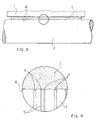
- Figure 4 shows diagrammatically, enlarged, the detail highlighted in Figure 3;
- Figure 5 shows diagrammatically, in a partial side view, a printing cylinder in contact with a doctor blade coated with a polymeric material, in particular Teflon s ®, with a dry lubricating material added;
- Figure 6 shows diagrammatically, enlarged, the detail highlighted in Figure 5.
- In the appended figures corresponding elements will be identified by means of the same reference numerals.
- A doctor blade produced according to the invention, able to operate in combination with a printing cylinder, comprises a metal support coated with a variable thickness layer of Teflon s ®, possibly with a solid material added, which comprises an ultrathin layer placed on the whole surface of the metal support of the doctor blade and a thicker layer placed over the ultrathin layer, which partially coats the surface of the doctor blade.
- The thicker layer coats one side of an edge of the doctor blade or both sides of an edge of the doctor blade or the same side of both edges of the doctor blade or both sides of both edges of the doctor blade or one side of the doctor blade or both sides of the doctor blade (figures 1a ― 1f).
- In any case, the thicker layer coats at least the side of the edge of the doctor blade that works in contact with the surface of a printing cylinder and the front head part of said side.
- The thickness of the ultrathin coating layer protecting the whole surface of the doctor blade is between 0,2 and 0,5 µm, preferably 0,3 µm; the thickness of the thicker layer, where applied with the object of improving the performance of the doctor blade or of the cylinder-doctor blade assembly, is between 1 and 10 µm, preferably 5 µm.
- Figure 1 shows diagrammatically some possible embodiments of a doctor blade produced according to the invention, wherein the ultrathin coating layer 0 (Figure 2), present on the whole surface of the
metal support 3 of thedoctor blade 1, has been omitted for the sake of simplicity of the graphic representation. - In particular:
- Figure la shows diagrammatically a
doctor blade 1 wherein one of the edges (4 or 5) of themetal support 3 of thedoctor blade 1 is coated on one side with thethicker layer 6; - Figure 1b shows diagrammatically a
doctor blade 1 wherein both edges (4, 5) of themetal support 3 of thedoctor blade 1 are coated on the same side with thethicker layer 6; - Figure 1c shows diagrammatically a
doctor blade 1 wherein one of the edges (4 or 5) of themetal support 3 of thedoctor blade 1 is coated on both sides with thethicker layer 6; - Figure 1d shows diagrammatically a
doctor blade 1 wherein both edges (4, 5) of themetal support 3 of thedoctor blade 1 are coated on both sides with thethicker layer 6; - Figure 1 e shows diagrammatically a
doctor blade 1 wherein one side of themetal support 3 of thedoctor blade 1 is completely coated with thethicker layer 6; - Figurelf shows diagrammatically a doctor blade wherein both sides of the
metal support 3 of thedoctor blade 1 are completely coated with thethicker layer 6. - Without departing from the scope of the invention, the
edges doctor blade 1 produced according to the invention can have the profile (rectangular, rounded, pre-sharpened with a foil or a bevel shape, etc.) considered most advantageous to meet specific requirements on a case-by-case basis. - The
metal support 3 is preferably made from a cold-rolled, hardened and tempered steel band with a polished surface having a roughness no greater than 2 µm. - The material selected for coating of the
doctor blade 1 forming the subject matter of the present invention is preferably Teflon s ®, possibly with solid material added; this choice ensures excellent adhesiveness of the coating to the polished surface of the metal support of the doctor blade. - Completely coating the whole surface of the
metal support 3 of adoctor blade 1 with an ultrathin layer 0 proves advantageous because thedoctor blade 1 is destined to operate in an environment and/or in contact with agents that are corrosive, highly oxidising, aggressive etc. which damage (or could damage) thesupport 3. - Coating, according to requirements, with a
thicker layer 6 one side of one edge (4 or 5) of thedoctor blade 1 or both sides of one edge (4 or 5) of thedoctor blade 1 or the same side of both edges (4, 5) of thedoctor blade 1 or both sides of both edges (4, 5) of thedoctor blade 1 or one side of thedoctor blade 1 or both sides of thedoctor blade 1 proves advantageous since the performance of the doctor blade-cylinder assembly is appreciably improved, as detailed hereunder. - The Applicant has verified experimentally that the formation on the
metal support 3 of the coating forming the subject matter of the present invention improves the contact betweendoctor blade 1 and cylinder and therefore the removal from the surface of the cylinder of excess liquids or dust during the scraping process. - The solid material possibly added to the Teflon s ® consists of metal micropowder and/or flakes and of dry lubricating material, even of metal carbides if necessary.
- The addition of solid material to the mixture advantageously serves to improve the characteristics of hardness, elasticity, resistance to the abrasion, lubricating and non-stick capability of the coating layer.
- The metal micropowders and/or flakes are, for example, aluminium, bronze, molybdenum, cobalt, etc.; they advantageously serve to remetallize any microporosities present on the surface of the cylinder during the scraping process.
- The dry lubricating material is preferably Teflon ®, or graphite, molybdenum sulphide, etc.; advantageously, these particles of dry lubricant serve to dry lubricate the cylinder.
- Furthermore these particles of dry lubricant are advantageously released during the scraping process and lubricate, by interposition, the metal-to-metal contact surfaces between the doctor blade and the cylinder; they thus drastically reduce friction and, consequently, wear on the doctor blade and on the cylinder surface.
- Moreover said particles of dry lubricant, which have non-stick properties, reduce the stickiness of the surface of the doctor blade and thus the undesired gathering and build-up of substances between the doctor blade and the cylinder surface.
- Metal carbides, which have microabrasive properties, if added to the Teflon s ®, advantageously serve to obtain the desired microtexture of the cylinder, particularly for rotogravure printing.
- The weight of the solid material added to the Teflon s ® of the
thicker layer 6 is between 10% and 40% of the overall weight of the coating layer of themetal support 3; the weight of the dry lubricating material added to thethicker layer 6 is between 5% and 30% of the overall weight of the coating layer of themetal support 3. - In general the coating is advantageously conceived to have a low surface tension and to repel the majority of the products to be scraped.
- It is further advantageously conceived to release molecular powders with opposite polarity to facilitate emptying of the cells of the cylinder during the scraping process.
- Figure 2 shows diagrammatically, enlarged, the detail highlighted in Figure 1f; in Figure 2 the
edge 4 of themetal support 3 coated with the ultrathin layer 0 and with athicker layer 6 of Teflon s ®, possibly with solid material added, which covers the front part and both sides of theedge 4 can be seen better. - Careful, repeated tests carried out by the Applicant have shown that, operating conditions being equal, wear on a doctor blade produced according to the present invention is about 25% less than that on the best-performing doctor blade of the prior art.
- Figure 3 shows diagrammatically a front view of a
doctor blade 1 placed in contact, along a line of contact indicated by 8 in Figures 3 and 4, with the surface of aprinting cylinder 2. - In Figure 3 the
doctor blade 1 is carried by adoctor blade holder 7, not described herein as it is per se known and in any case it is outside the scope of the present invention. - As can be seen from Figure 4 (which shows diagrammatically, enlarged, the detail highlighted in Figure 3), the
thicker layer 6 consisting of Teflon s ® possibly with added material penetrates (or can penetrate) into the flaws and into the scratches present on the surface of the cylinder 2 (represented in Figure 4 by a plurality of grooves 9), improving the adhesion of thedoctor blade 1 to the surface of thecylinder 2 and, consequently, the cleaning effect exerted by thedoctor blade 1 on said surface. - Figure 5 shows diagrammatically a partial side view of a
printing cylinder 2 in contact with adoctor blade 1 coated on its whole surface with an ultrathin layer 0 (omitted in Figure 5 for the sake of simplicity of the graphic representation) and on both sides with athicker layer 6 of Teflon s ®, possibly with added material. - The
metal support 3 of thedoctor blade 1 and alayer 10 of a material (for example ink) which coats the surface of thecylinder 2 and which is removed by thedoctor blade 1 can also be seen in Figure 5; the direction of rotation of thecylinder 2 is indicated in Figures 5 and 6 by means of thearrow 11. - As can be seen better from Figure 6 (which shows diagrammatically, enlarged, the detail highlighted in Figure 5), during operation the coating layer which coats the front part of the
doctor blade 1 is consumed rapidly and only thesupport 3 and the twothicker layers 6 are in contact with the surface of the cylinder 2: the dry lubricating material released by the twolayers 6 facilitates sliding of thedoctor blade 1 on the surface of thecylinder 2 and detachment from the surface of thecylinder 2 of the layer ofmaterial 10, which slides along thelayer 6 of thedoctor blade 1 before losing adhesion and falling. - There will now be described the deposition method of the present invention for obtaining the above described variable thickness layer, that is, for distributing a coating varying in thickness from 0,2 to 10,5 µm in a continuous manner along the surface of a
metal support 3 consisting of a steel band, which comprises the following steps: - covering both sides of the moving
metal support 3 with a superabundant layer of Teflon s ® by dipping, spraying or pouring onto the surface of thesupport 3; - removing the excess amount of Teflon s ®, by means of a doctor blade or by means of shaped calibrating rollers, so as to leave on the surface of the
metal support 3 the ultrathin layer 0 and thethicker layer 6; and - immediately inserting the
metal support 3 thus coated into a thermal device (not described in that it is per se known) to fix and to sinter the coating layer applied.. - Without departing from the scope of the invention, a person skilled in the art can make to the doctor blade and to the production method previously described all the modifications and the improvements suggested by the normal experience and/or by the natural evolution of the art.
Claims (15)
- A doctor blade (1), consisting in a support (3) coated with a coating layer of polymeric material, characterized in that said coating layer has a variable thickness and comprises an ultrathin layer (0) placed on the whole surface of the support (3) and a thicker layer (6), placed over the ultrathin layer (0), which partially coats the surface of the doctor blade (1).
- A doctor blade (1) as in claim 1, characterised in that the thicker layer (6) coats at least the side of the edge of the doctor blade (1) which works in contact with the surface of a printing cylinder (2) and the front head part of said side.
- A doctor blade (1) as in claim 2, characterised in that the thicker layer (6) coats one side of one edge (4, 5) of the doctor blade (1) or both sides of one edge (4, 5) of the doctor blade (1) or the same side of both edges (4, 5) of the doctor blade (1) or both sides of both edges (4, 5) of the doctor blade (1) or one side of the doctor blade (1) or both sides of the doctor blade (1).
- A doctor blade (1) as in claim 1, characterised in that the support (3) is produced from a cold rolled, hardened and tempered steel band with a polished surface having a roughness no greater than 2 µm.
- A doctor blade (1) as in claim 1, characterised in that the polymeric material is Teflon s ®.
- A doctor blade (1) as in claim 1, characterized in that the ultrathin layer (0) has a thickness between 0,2 and 0,5 µm, preferably 0,3 µm, and the thicker layer (6) has a thickness between 1 and 10 µm, preferably 5 µm.
- A doctor blade (1) as in claim 1, characterised in that the polymeric material of the thicker layer (6) has solid material added.
- A doctor blade (1) as in claim 7, characterised in that the solid material added to the polymeric material comprises metal micropowders and/or flakes and dry lubricating material.
- A doctor blade (1) as in claim 7, characterised in that the solid material added to the polymeric material further comprises metal carbides.
- A doctor blade (1) as in claim 7, characterised in that the weight of solid material added to the polymeric material of the thicker layer (6) is between 10% and 40% of the overall weight of the coating layer of the support (3) and the weight of the dry lubricating material added to the polymeric material of the thicker layer (6) is between 5 % and 30 % of the overall weight of the coating layer of the support (3).
- A doctor blade (1) as in claim 8, characterised in that the dry lubricating material consists of Teflon ®, molybdenum sulphide or graphite.
- A doctor blade (1) as in claim 11, characterised in that the dry lubricating material is Teflon ®.
- A doctor blade (1) as in claim 8, characterised in that the metal micropowders and/or flakes consist of aluminium, bronze, molybdenum or cobalt.
- A method of producing a doctor blade (1), as in at least one of the preceding claims by coating the surface of the support (3) with a variable thickness layer of a polymeric material, characterised in that it comprises the following steps:- coating both sides of the moving support (3) with a superabundant layer of polymeric material;- removing the excess amount of polymeric material, by means of a doctor blade or of shaped calibrating rollers, so as to leave on the surface of the support (3) the ultrathin layer (0) and the thicker layer (6); and- immediately introducing the metal support (3) thus coated into a thermal device to fix and to sinter the coating layer applied.
- A method as in claim 14, characterised in that the superabundant layer of polymeric material is applied to the moving support (3) by dipping, spraying or pouring onto the support (3).
Priority Applications (1)
| Application Number | Priority Date | Filing Date | Title |
|---|---|---|---|
| EP20060013914 EP1745863A3 (en) | 2005-07-21 | 2006-07-05 | Doctor blade coated with polymeric material and coating method |
Applications Claiming Priority (2)
| Application Number | Priority Date | Filing Date | Title |
|---|---|---|---|
| EP20050425525 EP1745862A1 (en) | 2005-07-21 | 2005-07-21 | Doctor blade coated with a polymeric material, designed to operate in combination with a printing cylinder |
| EP20060013914 EP1745863A3 (en) | 2005-07-21 | 2006-07-05 | Doctor blade coated with polymeric material and coating method |
Publications (2)
| Publication Number | Publication Date |
|---|---|
| EP1745863A2 true EP1745863A2 (en) | 2007-01-24 |
| EP1745863A3 EP1745863A3 (en) | 2010-06-30 |
Family
ID=35464083
Family Applications (2)
| Application Number | Title | Priority Date | Filing Date |
|---|---|---|---|
| EP20050425525 Withdrawn EP1745862A1 (en) | 2005-07-21 | 2005-07-21 | Doctor blade coated with a polymeric material, designed to operate in combination with a printing cylinder |
| EP20060013914 Withdrawn EP1745863A3 (en) | 2005-07-21 | 2006-07-05 | Doctor blade coated with polymeric material and coating method |
Family Applications Before (1)
| Application Number | Title | Priority Date | Filing Date |
|---|---|---|---|
| EP20050425525 Withdrawn EP1745862A1 (en) | 2005-07-21 | 2005-07-21 | Doctor blade coated with a polymeric material, designed to operate in combination with a printing cylinder |
Country Status (3)
| Country | Link |
|---|---|
| US (1) | US7632560B2 (en) |
| EP (2) | EP1745862A1 (en) |
| BR (1) | BRPI0603147A (en) |
Cited By (1)
| Publication number | Priority date | Publication date | Assignee | Title |
|---|---|---|---|---|
| CN113059015A (en) * | 2021-03-29 | 2021-07-02 | 浙江钱富万向节有限公司 | Environment-friendly intelligent processing technology for lubricating and coating cold extruded blank |
Families Citing this family (17)
| Publication number | Priority date | Publication date | Assignee | Title |
|---|---|---|---|---|
| WO2008025172A1 (en) * | 2006-08-29 | 2008-03-06 | Daetwyler Swiss Tec Ag | Doctor blade |
| CH699600A1 (en) * | 2008-09-30 | 2010-03-31 | Daetwyler Swisstec Ag | Squeegee. |
| BR112012018078B8 (en) * | 2010-01-20 | 2022-05-31 | Daetwyler Swisstec Ag | Scraper and process for your production |
| DE102010062901A1 (en) * | 2010-12-13 | 2012-06-14 | Voith Patent Gmbh | Impregnated blade coating |
| ITFI20110254A1 (en) * | 2011-11-24 | 2013-05-25 | Futura Spa | DEVICE FOR REMOVING WASTE AND CYLINDER RESIDUES FROM CYLINDERS OF PLANTS FOR THE TREATMENT OF NASTRIFORM PAPER MATERIAL. |
| US9539605B2 (en) * | 2012-02-28 | 2017-01-10 | Toray Plastics (America), Inc. | Gravure roll edge masking system for in-line film coating |
| GB2514139A (en) | 2013-05-14 | 2014-11-19 | Aghababaie Lin & Co Ltd | Apparatus for fabrication of three dimensional objects |
| US10166725B2 (en) | 2014-09-08 | 2019-01-01 | Holo, Inc. | Three dimensional printing adhesion reduction using photoinhibition |
| US9573357B2 (en) | 2014-12-12 | 2017-02-21 | Patricia G. Bordeaux | One-piece foam frame for mounting screen and/or screen stencil film to create screens for manual and small off-contact printing substrates |
| US11141919B2 (en) | 2015-12-09 | 2021-10-12 | Holo, Inc. | Multi-material stereolithographic three dimensional printing |
| EP3178654A1 (en) * | 2015-12-10 | 2017-06-14 | Daetwyler Swisstec Ag | Scraper |
| US10935891B2 (en) | 2017-03-13 | 2021-03-02 | Holo, Inc. | Multi wavelength stereolithography hardware configurations |
| GB2564956B (en) | 2017-05-15 | 2020-04-29 | Holo Inc | Viscous film three-dimensional printing systems and methods |
| US10245785B2 (en) | 2017-06-16 | 2019-04-02 | Holo, Inc. | Methods for stereolithography three-dimensional printing |
| EP3902659A4 (en) | 2018-12-26 | 2022-09-07 | Holo, Inc. | Sensors for three-dimensional printing systems and methods |
| WO2022225854A1 (en) | 2021-04-19 | 2022-10-27 | Holo, Inc. | Systems and methods for stereolithography three-dimensional printing |
| DE102023100481A1 (en) * | 2023-01-11 | 2024-07-11 | Clouth Sprenger Gmbh | Scraper blade with rounded contact tip |
Citations (5)
| Publication number | Priority date | Publication date | Assignee | Title |
|---|---|---|---|---|
| NL9300810A (en) | 1993-05-12 | 1994-12-01 | Johannes Joseph Gerardus Linss | System for distributing a medium over a pitted surface |
| US20020157548A1 (en) | 2001-02-16 | 2002-10-31 | Antoine Beran | Self-adjusting blade |
| DE20216494U1 (en) | 2002-10-25 | 2003-01-02 | Voith Paper Patent GmbH, 89522 Heidenheim | Fluid spreading rod for paper or carton surface preparation process, has elastic contact surface |
| US20040137261A1 (en) | 2000-12-07 | 2004-07-15 | Allan Lunnerfjord | Doctor or coater blade and method in connection with its manufacturing |
| US20050089706A1 (en) | 2002-01-29 | 2005-04-28 | Kazuya Urata | Surface treated doctor blade |
Family Cites Families (5)
| Publication number | Priority date | Publication date | Assignee | Title |
|---|---|---|---|---|
| US4755434A (en) * | 1984-12-07 | 1988-07-05 | Kansai Paint Co., Ltd. | Process for coating metallic substrate |
| SE507926C2 (en) * | 1996-12-19 | 1998-07-27 | Btg Kaelle Inventing Ab | Coating sheet for coating a running track |
| JP2005515312A (en) * | 2002-01-11 | 2005-05-26 | エス・ディ・ウォレン・サーヴィシーズ・カンパニー | Composite doctor blade |
| JP3826058B2 (en) * | 2002-03-25 | 2006-09-27 | イチカワ株式会社 | Draining doctor blade |
| US6907210B2 (en) * | 2003-09-13 | 2005-06-14 | Wazana Brothers International, Inc. | Remanufactured toner cartridge having modified roller section |
-
2005
- 2005-07-21 EP EP20050425525 patent/EP1745862A1/en not_active Withdrawn
-
2006
- 2006-07-05 EP EP20060013914 patent/EP1745863A3/en not_active Withdrawn
- 2006-07-11 US US11/483,611 patent/US7632560B2/en active Active
- 2006-07-20 BR BRPI0603147-1A patent/BRPI0603147A/en not_active Application Discontinuation
Patent Citations (5)
| Publication number | Priority date | Publication date | Assignee | Title |
|---|---|---|---|---|
| NL9300810A (en) | 1993-05-12 | 1994-12-01 | Johannes Joseph Gerardus Linss | System for distributing a medium over a pitted surface |
| US20040137261A1 (en) | 2000-12-07 | 2004-07-15 | Allan Lunnerfjord | Doctor or coater blade and method in connection with its manufacturing |
| US20020157548A1 (en) | 2001-02-16 | 2002-10-31 | Antoine Beran | Self-adjusting blade |
| US20050089706A1 (en) | 2002-01-29 | 2005-04-28 | Kazuya Urata | Surface treated doctor blade |
| DE20216494U1 (en) | 2002-10-25 | 2003-01-02 | Voith Paper Patent GmbH, 89522 Heidenheim | Fluid spreading rod for paper or carton surface preparation process, has elastic contact surface |
Cited By (1)
| Publication number | Priority date | Publication date | Assignee | Title |
|---|---|---|---|---|
| CN113059015A (en) * | 2021-03-29 | 2021-07-02 | 浙江钱富万向节有限公司 | Environment-friendly intelligent processing technology for lubricating and coating cold extruded blank |
Also Published As
| Publication number | Publication date |
|---|---|
| US7632560B2 (en) | 2009-12-15 |
| BRPI0603147A (en) | 2007-03-13 |
| US20070017392A1 (en) | 2007-01-25 |
| EP1745863A3 (en) | 2010-06-30 |
| EP1745862A1 (en) | 2007-01-24 |
Similar Documents
| Publication | Publication Date | Title |
|---|---|---|
| US7632560B2 (en) | Doctor blade coated with polymeric material and coating method | |
| RU2411130C2 (en) | Pre-honed scraper, having plate with curved profile, and method to make specified scraper | |
| AU672548B2 (en) | Method and apparatus for handling printed sheet material | |
| JP5463713B2 (en) | Doctor for gravure coating | |
| EP1469996B1 (en) | Surface treated doctor blade | |
| JP5373917B2 (en) | Diamond coated doctor blade | |
| EP1777076A1 (en) | Jacket for impression cylinder or transport cylinder of printing press | |
| US7562858B2 (en) | Wear and texture coatings for components used in manufacturing glass light bulbs | |
| SE526191C2 (en) | Egg-provided tools and methods for making them | |
| CN108367565B (en) | Doctor blade and method for producing a doctor blade | |
| JP6891171B2 (en) | Use of doctor blades in doctor blades, ink devices, and flexographic printing | |
| MX2011003423A (en) | Doctor blade. | |
| JP2003024850A (en) | Coating equipment | |
| DE102005062204A1 (en) | Wear protection coating (5) for printing press elements subject to surface corrosion and/or adhesive and/or abrasive loads useful in the printing industry applied by chemical or physical deposiion ferom the gas phase | |
| JP3620713B2 (en) | Doctor blade and manufacturing method thereof | |
| CN215620713U (en) | Bearing roller and have its coating machine | |
| JP2005262152A (en) | Roll coater device | |
| HK1252795B (en) | Squeegee and method for manufacturing a squeegee | |
| JP2950081B2 (en) | Doctor blades for hard rolls of papermaking machines | |
| WO2024231505A2 (en) | Method for producing a coated tool by means of metallic coating of plastics, and a coated tool | |
| JP2005246765A (en) | Doctor blade | |
| JP5110745B2 (en) | Non-lubricating die | |
| JP2540519B2 (en) | Ink supply device doctor blade | |
| NL8702724A (en) | Wear resistant electrodeposited surface layer - comprising metal layer with protruding abrasion resistant particles and chromium layer thick enough to cover protruding particles | |
| JPH07116928A (en) | Facing material manufacturing method |
Legal Events
| Date | Code | Title | Description |
|---|---|---|---|
| PUAI | Public reference made under article 153(3) epc to a published international application that has entered the european phase |
Free format text: ORIGINAL CODE: 0009012 |
|
| AK | Designated contracting states |
Kind code of ref document: A2 Designated state(s): AT BE BG CH CY CZ DE DK EE ES FI FR GB GR HU IE IS IT LI LT LU LV MC NL PL PT RO SE SI SK TR |
|
| AX | Request for extension of the european patent |
Extension state: AL BA HR MK YU |
|
| PUAL | Search report despatched |
Free format text: ORIGINAL CODE: 0009013 |
|
| AK | Designated contracting states |
Kind code of ref document: A3 Designated state(s): AT BE BG CH CY CZ DE DK EE ES FI FR GB GR HU IE IS IT LI LT LU LV MC NL PL PT RO SE SI SK TR |
|
| AX | Request for extension of the european patent |
Extension state: AL BA HR MK RS |
|
| 17P | Request for examination filed |
Effective date: 20101124 |
|
| AKX | Designation fees paid |
Designated state(s): AT BE BG CH CY CZ DE DK EE ES FI FR GB GR HU IE IS IT LI LT LU LV MC NL PL PT RO SE SI SK TR |
|
| 17Q | First examination report despatched |
Effective date: 20160229 |
|
| STAA | Information on the status of an ep patent application or granted ep patent |
Free format text: STATUS: THE APPLICATION IS DEEMED TO BE WITHDRAWN |
|
| 18D | Application deemed to be withdrawn |
Effective date: 20160712 |