EP1745310B1 - Auto-deep scan for capacitive sensing - Google Patents
Auto-deep scan for capacitive sensing Download PDFInfo
- Publication number
- EP1745310B1 EP1745310B1 EP05713484.3A EP05713484A EP1745310B1 EP 1745310 B1 EP1745310 B1 EP 1745310B1 EP 05713484 A EP05713484 A EP 05713484A EP 1745310 B1 EP1745310 B1 EP 1745310B1
- Authority
- EP
- European Patent Office
- Prior art keywords
- capacitance
- sensor
- plate
- measurement
- ratio
- Prior art date
- Legal status (The legal status is an assumption and is not a legal conclusion. Google has not performed a legal analysis and makes no representation as to the accuracy of the status listed.)
- Expired - Lifetime
Links
- 238000005259 measurement Methods 0.000 claims description 117
- 238000000034 method Methods 0.000 claims description 41
- 230000007704 transition Effects 0.000 claims description 38
- 239000003990 capacitor Substances 0.000 claims description 24
- 230000008859 change Effects 0.000 claims description 22
- 230000008569 process Effects 0.000 description 11
- 230000000694 effects Effects 0.000 description 6
- 239000000463 material Substances 0.000 description 4
- 230000003071 parasitic effect Effects 0.000 description 3
- 230000035945 sensitivity Effects 0.000 description 3
- 230000000007 visual effect Effects 0.000 description 3
- 238000004590 computer program Methods 0.000 description 2
- 238000010276 construction Methods 0.000 description 2
- 238000001514 detection method Methods 0.000 description 2
- 238000010586 diagram Methods 0.000 description 2
- 230000009977 dual effect Effects 0.000 description 2
- 239000010410 layer Substances 0.000 description 2
- 238000004519 manufacturing process Methods 0.000 description 2
- 239000002356 single layer Substances 0.000 description 2
- 239000002023 wood Substances 0.000 description 2
- 239000011449 brick Substances 0.000 description 1
- 238000004364 calculation method Methods 0.000 description 1
- 230000006870 function Effects 0.000 description 1
- 229910052602 gypsum Inorganic materials 0.000 description 1
- 239000010440 gypsum Substances 0.000 description 1
- 239000004973 liquid crystal related substance Substances 0.000 description 1
- 239000002184 metal Substances 0.000 description 1
- 230000001603 reducing effect Effects 0.000 description 1
- 230000008439 repair process Effects 0.000 description 1
Images


Classifications
-
- G—PHYSICS
- G01—MEASURING; TESTING
- G01V—GEOPHYSICS; GRAVITATIONAL MEASUREMENTS; DETECTING MASSES OR OBJECTS; TAGS
- G01V3/00—Electric or magnetic prospecting or detecting; Measuring magnetic field characteristics of the earth, e.g. declination, deviation
- G01V3/08—Electric or magnetic prospecting or detecting; Measuring magnetic field characteristics of the earth, e.g. declination, deviation operating with magnetic or electric fields produced or modified by objects or geological structures or by detecting devices
- G01V3/088—Electric or magnetic prospecting or detecting; Measuring magnetic field characteristics of the earth, e.g. declination, deviation operating with magnetic or electric fields produced or modified by objects or geological structures or by detecting devices operating with electric fields
Definitions
- This invention relates to an electronic sensor, and, in particular, to a sensor suitable for detecting the location of an object behind a variety of surfaces, such as walls, floors and other non-electrically conductive structures (but not limited to building structures). More specifically, the invention relates to an electronic sensor useful to detect centerlines and edges of wall studs, floor joists, and the like.
- a "stud” is a structural member of a building to which an interior wall surface such as wall board or paneling is affixed.
- 2-by-4" wooden studs are used in construction. Nominally, a 2-by-4 stud is 51 mm (2 inches) wide and 102 mm (4 inches) deep and of any suitable length. The actual dimensions of a 2-by-4 are more typically 38 mm (1 1 ⁇ 2 inches) wide and 89 mm (3 1 ⁇ 2 inches) deep.
- Use of English (inches) units and U.S. stud sizes here is in conformance with U.S. construction practice and is not intended to be limiting, but is only illustrative. Finding studs is a typical problem for building repairs, picture hanging, etc.
- the sensor detects the stud by measuring a change in capacitance due to a change in the dielectric constant along the wall. Due to the placement of the studs, a wall surface exhibits changing dielectric constants while the sensor is moved along the wall surface.
- the sensor includes a plurality of capacitor plates, a circuit for detecting changes in the capacitance, and an indicator.
- the plurality of capacitor plates is mounted in the sensor such that they can be positioned close to a wall's surface.
- the circuit detects a change in the capacitance of the plates due to a change in the average dielectric constant of the surface.
- the capacitor plates are used to measure the effective capacitance or change in capacitance of a wall. Before detection begins, the sensor first performs a calibration to null out the effect of a wall in the absence of a stud.
- the capacitor plates are composed of a center plate and a symmetric pair of electrically connected edge plates. A difference in capacitance between the center and edge plates is used to determine the location of the edge of a stud. The centerline of the stud is then determined by finding both the left and right edges of the stud and then measuring to the middle of the distance between the edges. Thus, multiple measurements must be made in order to determine the centerline of the stud.
- the indicator indicates a change in capacitance of the capacitor plate, thereby alerting an operator to the wall stud position. The indicator also alerts the operator when calibration is occurring.
- the ballooning may be asymmetric due to electrical wires, metallic pipes and other objects in close proximity to the stud, which in turn may lead to a reduced ability to accurately determine a stud's centerline.
- location of an edge of a stud can be inaccurately indicated by as much as 51 mm (2 inches).
- the centerline of the stud may be so inaccurately indicated that it is completely off the actual stud location.
- US 5917314 describes a device for locating the edges of wall studs including a comparison circuit connected to each of three capacitive elements. As the device is moved along a wall, the comparison circuit monitors the relative charge time associated with each capacitive element, the charge times providing an indication of the relative capacitances of the three capacitive elements. Changes in the relative capacitances of the three elements as the device is moved along a wall are due to a change in the dielectric constant of the wall, which normally results from the presence of a wall stud behind the surface over which the device is moved. The comparison circuit uses differences in the measured relative capacitances of the first, second, and third capacitive elements to locate the edges of the stud.
- An apparatus and method for determining a feature of a member located behind a surface while reducing effects of an unknown thickness of the member are provided.
- the feature is a centerline of a building object or member, such as a stud or joist but is not so limited.
- the sensor apparatus includes a plurality of capacitive plates.
- One aspect of the invention provides method of finding a feature behind a surface according to claim 1.
- a second aspect of the invention provides a sensor for finding a feature of a structure according to claim 19.
- the sensor may also include circuitry to sense an effective capacitance created by a plate, the covering and objects behind the covering.
- the sensor may compute a ratio between the capacitance measurements of a pair of the plates. A ratio of approximately one may indicate a centerline of a stud or joist or similar member. A ratio in a predetermined range may indicate an edge of a stud or joist. Additionally, the sensor may analyze a capacitance measurement to determine a depth of the feature.
- Some embodiments of the invention provide a method of finding a feature behind a surface using a sensor having a first plate and a second plate of approximately equal areas, the method comprising the acts of: moving the sensor and surface adjacent one another; measuring a first capacitance of a first capacitor including the first plate and the feature; measuring a second capacitance of a second capacitor including the second plate and the feature; comparing the first capacitance measurement to the second capacitance measurement; comparing one of the first or second capacitance measurements with a first threshold; and repeating the acts of measuring and comparing.
- Some embodiments of the invention provide a sensor for finding a feature of a structure comprising: a first plate having a first capacitance and adapted for forming a first capacitor with the structure; a second plate having a second capacitance and adapted for forming a second capacitor with the structure; a first measurement circuit coupled to the first plate, the first measurement circuit measuring a first capacitance value of the first capacitor; a second measurement circuit coupled to the second plate, the second measurement circuit measuring a second capacitance value of the second capacitor; and a comparison circuit coupled to the first and second measurement circuits, the comparison circuit generating a ratio of the first and second capacitance values and comparing one of the first or second capacitance values to a first threshold.
- Some embodiments of the invention provide a sensor comprising: a first plate and a second plate positioned in about the same plane and spaced apart, and adapted to be located adjacent a surface; a measurement circuit coupled to the first and second plates thereby to measure a capacitance value of each of the plates; a first comparison circuit coupled to receive the measured capacitance values and determine a ratio between a change in the measured capacitance values; and a second comparison circuit coupled to receive one of the measured capacitance values and a threshold and to provide a comparison therebetween.
- a procedure, computer executed step, logic block, process, etc. are here conceived to be a self-consistent sequence of steps or instructions leading to a desired result.
- the steps are those utilizing physical manipulations of physical quantities. These quantities can take the form of electrical, magnetic, or radio signals capable of being stored, transferred, combined, compared, and otherwise manipulated in a computer system. These signals may be referred to at times as bits, values, elements, symbols, characters, terms, numbers, or the like.
- Each step may be performed by hardware, software, firmware, or combinations thereof.
- a ratiometric capacitive sensor may use capacitance measurements from multiple conductive plates to determine the presence of objects, such as studs and joists, hidden behind a covering surface such as a wall, floor, ceiling, etc.
- a ratiometric capacitive sensor includes two conductive plates. Each conductive plate acts as part of a separate capacitor. Circuitry coupled to each plate measures an effective change in capacity of the separate capacitors, which is effected by the density of material in close proximity to the plates. As a result, a wall or other surface covering combined with an underlying stud or other member form a larger capacitance than a wall covering alone without a stud. A capacitance measurement may be taken from each plate. The capacitance measurement from one plate may then be compared to a capacitance measurement of another plate to determine boundaries and features of the materials in the vicinity of the plates.
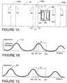
- FIGURE 1A illustrates a plan view of a capacitive sensor 300 having two primary plates 301, 302, in accordance with the present invention.
- the sensor 300 is positioned against a wall 99 at a lateral distance D away from a hidden stud 100A.
- a wall may have multiple studs 100 (e.g., 100A, 100B and 100C).
- Each stud 100 has two edges 102 and defines a centerline 101 relative to its positioning along the wall 99.
- sensor 300 defines a centerline 304 that may be equally positioned between a first plate 301 and a second plate 302.
- associated circuitry and/or software operates to independently measure values indicative of a capacitance of each plate 301 and 302.
- FIGURES 1B and 1C illustrate a capacitance produced between each respective plate 301 and 302 of the sensor 300 and the wall 99.
- FIGURE 1B shows a capacitance curve 310 produced by the first plate 301 and the wall 99.
- FIGURE 1C shows a capacitance curve 320 produced by the second plate 302 and the wall 99.
- Capacitance curves 310 and 320 are drawn relative to the centerline 304 of the sensor 300. Additionally, curves 310 and 320 show peaks when respective plates 301 and 302 are positioned over the centerline 101 of a stud 100 and show valleys when respective plates 301 and 302 are positioned between pairs of studs 100.
- sensor 300 may be positioned far from any stud 100.
- the measured capacitance values increase as the sensor 300 nears the stud 100; however, the capacitance values of each plate 301 and 302 will differ if one of the plates is closer to the stud 100.
- a first plate 301 may be close to or over an edge 102 of a stud 100.
- the second plate 302 may still be positioned at a lateral distance away from the stud 100. In this case, the change in capacitance from its minimum value experienced by the first plate 301 will be greater than the change in capacitance experienced by the second plate 302.
- the capacitance measurements are used to calculate a ratio.
- a first capacitance measurement represents the change in capacitance from a calibration value experienced on a first plate 301.
- a second capacitance measurement represents the change in capacitance from a calibration value experienced on a second plate 302.
- a ratio between the first and second capacitance measurements may be computed. If the ratio is approximately equal to a determined value, it may be realized that a centerline 304 of the sensor 300 is centered over an edge 102 of a stud 100. If the capacitance measurements are equal or the ratio is approximately equal to unity, both plates may be centered over the stud's edge 102 and the centerline 304 of the sensor 300 may be centered over the centerline 101 of the stud 100.
- FIGURE ID shows overlapping first and second capacitance curves 310 and 320 relative to the centerline 304 of the sensor 300 and a stud 100.
- a point at which curves 310 and 320 intersect may indicate a position of the sensor 300 where each plate is encountering an equal capacitance; therefore, the centerline 304 of the sensor 300 may be directly over a centerline 101 of the stud 100.
- at least one of the capacitance values must be above a floor threshold value, a value above a calibration capacitance value, before the capacitance measurements are compared with each other.
- FIGURE IE shows a graph of a curve 330, which represents a ratio of capacitance measurements of two primary plates 301, 302 versus a lateral distance between a ratiometric capacitive sensor's centerline 304 and a centerline 101 of a stud 100, in accordance with the present invention.
- This ratio may be computed as the smaller capacitance divided by the larger capacitance, thereby resulting in a ratio that is equal to or less than one.
- the calculated results shown in a ratio curve 330, exhibits a sharp peak.
- the sharp peak of curve 330 allows a ratiometric sensor to locate a stud's centerline 101 with increased accuracy over non-ratiometric sensor, which may generate rounded peaked curves.
- a transition ratio may be compared to the calculated ratio to determine the location of an edge 102 of a stud 100 as further described below.
- the transition ratio predicts a capacitance ratio formed at an edge of a stud when the sensor 300 is centered over the stud's edge for a particular wall structure. As such, a transition ratio may be used to indicate when the sensor 300 is centered over an edge 102.
- a transition ratio may be determined in a number of ways.
- the transition ratio may be a factory set constant. Alternatively, the transition ratio may be set by an operator. In some embodiments, the transition ratio is calculated during operation.
- a transition ratio may be set during manufacturing as a factory set constant. For example, a factory may set a transition ratio equal to a fixed value, e.g., 0.33. When plates produce capacitance measurements that form a ratio approximately equal to 0.33, sensor 300 may indicate that the center of sensor 300 is directly over an edge 102 of stud 100.
- a transition ratio may be directly or indirectly selected by an operator of the sensor.
- an operator may select a stud width and/or a wall thickness.
- the stud width and/or wall thickness may be used to select an appropriate transition ratio, for example, as shown in the table below.
- a transition ratio may be automatically determined by the sensor 300 based on capacitance measurements.
- a capacitance measurement may be a measure of a maximum capacitance measurement on a plate as shown in FIGURE 3 .
- a maximum measured capacitance value may be used to set a transition ratio used to locate a stud's edge. This maximum value may indicate a wall covering's thickness, with thicker walls having smaller maximum values. The maximum value may also provide an indication of the width of the stud, with wider studs having larger maximum values. The measured capacitance values may also be compared to indicate a direction of a stud with the plate having a higher capacitance measurement indicating the direction of the center of the stud.
- plate capacitance is measured by determining a time it takes to charge a plate 301 or 302 to a determined value. In other embodiments, plate capacitance is measured by determining a voltage that charges a plate 301 or 302 within a determined time. In either case, an output of a digital-to-analog converter ("DAC") may provide a voltage used to charge the plate.
- a DAC output may be represented by a digital input value.
- An input to the DAC may be supplied from a counter, such as an up/down counter, or may be supplied from a microcontroller or microprocessor. This input value may be referred to as a DAC count.
- a DAC count may have a determined reference point. For example, a DAC value may be referenced from zero. Alternatively, a DAC value may be referenced from a value determined from calibration processing or the like.
- each plate 301 and 302 may be partially over the stud 100.
- Each plate 301 and 302 will have a capacitance value that is some minimum threshold above its calibration value, below its maximum value, and approximately equal to a common value. Therefore, a centerline of an object may be located by identifying when two plates have capacitance values equal to a common value that is above some floor threshold value.
- a covering of wall (surface) 99 may be of different thicknesses.
- a thin wall covering will exhibit a low nominal capacitance, where as a thicker wall covering will exhibit a higher nominal capacitance.
- a stud positioned behind a thin wall covering will produce a high maximum capacitance.
- a stud position behind a thicker wall covering will be farther away from the wall's external surface and therefore will produce a lower maximum capacitance.
- FIGURE 2C shows capacitance curves for two plates 301, 302 for a sensor 300 that has been pulled across a wall 99.
- sensor 300 measures capacitances shown on curves 310A and 320A for respective plates 301 and 302.
- sensor 300 measures lower capacitance values as shown in curves 310B and 320B.
- Lower capacitance values may represent a deeper (farther behind wall 99) or narrower stud. Alternatively, higher capacitance values may represent a shallower or wider stud.
- Sensor 300 may compare capacitance measurements to a depth threshold. For example, when sensor 300 is positioned over an edge of a stud, a center of a stud, or between edges of a stud, sensor 300 may indicate whether or not the detected stud is a deep stud or not a deep stud.
- the indication may be an audio indication, such as from a buzzer in sensor 300, a visual indication, such as from an LED, a signal level, such as supplied to a control line, or any combination thereof.
- the indication of a depth of a feature may be used by the sensor operator. For example, if most features are determined to originate from a non-deep stud, the operator may conclude that deep features are anomalies. Similarly, if most features are determined to be deep, then any non-deep features may be ignored by the operator.
- each stud will produce a different capacitance measurement when sensor 300 is centered over the stud. For example, when sensor 300 is centered over stud 100A, DAC counts of 80 above calibration values on each plate may result. When sensor 300 is centered over stud 100B, DAC counts of 30 above the calibration values on each plate may result.
- Plates producing equal measurements above a floor threshold indicate that the sensor is centered over the stud. Additionally, a higher DAC count indicates that the stud is closer to the surface, the stud is wider than a reference stud and surface, or a material of higher conductivity is detected.
- An example DAC count of 80 may represent that a single-width stud is positioned behind a single-layer of sheetrock.
- An example DAC count of 30 may represent that a single-width stud is positioned behind a double-layer of sheetrock.
- a transition ratio may be calculated by sensor 300 based on a historic maximum capacitance measurement. In other embodiments, the transition ratio may be calculated based on an instantaneous maximum capacitance measurement.
- a historic maximum capacitance measurement may be determined over time as measured from either plate 301 or 302.
- a maximum capacitance measurement is expected when the plate 301 or 302 is centered over a stud.
- the maximum capacitance measurement may be saved in memory of sensor 300. As the capacitance changes over time, an updated maximum capacitance value may be stored.
- a capacitance measurement may be used.
- a capacitance measurement may be selected each time the sensor 300 takes each pair of capacitance measurements from plates 301 and 302.
- the instantaneous capacitance value may be determined by examining the capacitance formed by a single plate 301. In some embodiments, the instantaneous capacitance value is determined over a period of time, e.g., by a moving average or the like.
- the sensor 300 may select a transition ratio from a table or compute a transition ratio from a formula.
- a sensor 300 having plates centered 38 mm (1 1 ⁇ 2 inches) apart, with each plate 19 mm (3 ⁇ 4 of an inch) wide, may use a transition ratio as shown in the table below.
- a capacitance measurement of 1.4 representing a double-width stud hidden behind a single sheet of sheetrock, may have a transition ratio of 0.32.
- a lookup table in the memory of sensor 300 may be used to map a capacitance measurement to a transition ratio.
- the sensor 300 may compute a transition ratio for each ratio calculation.
- the design constant P 1 / 2 may be set during manufacturing and may represent the expected maximum capacitance measured over a reference wall structure having a single (nominal) stud having a width of 44 mm (1 3 ⁇ 4 inches) and a wall covering 99 having a thickness of 13 mm (1 ⁇ 2 of an inch).
- the capacitance C parameter may be the historical maximum capacitance.
- the capacitance C parameter may be the instantaneous maximum capacitance of two plate measurements as described above.
- the formula shows that if C is less than the design constant P 1 / 2 , the formula is used. If C is greater than or equal to the design constant P 1 / 2 , a fix value of 0.33 is used.
- the transition ratio may be used to indicate whether the sensor is centered over an edge of a stud.
- Sensor 300 may measure a first capacitance value on a first plate 301 and a second capacitance value on a second plate 302.
- a capacitance ratio may be calculated between the first and second capacitance values. This capacitance ratio may be compared to the predicted transition ratio to determine whether the sensor 300 is presently centered over an edge 102 of a stud 100.
- sensor 300 measuring a larger capacitance value of 1.4 may indicate the sensor 300 has passed over a double-wide stud having a width of 76 mm (3 inches) hidden behind a single layer of sheetrock having a thickness of 13 mm (1 ⁇ 2 an inch).
- the transition ratio for this wall structure may be set to a value of 0.32.
- the sensor 300 may indicate that the sensor 300 is centered over an edge 102.
- the stud's edge location may be determined to an accuracy of approximately 3 mm (1/8 of an inch) over a wall covering thickness range of 13 to 25 mm (1 ⁇ 2 to 1 inch).
- Measured capacitance values indicate a direction in which a stud 100 is located. At a stud's edge 102, one plate may be directly over the centerline 101 of the stud 100, while the other may be off to one side of the stud 100.
- the plate 301 or 302 positioned over the stud 100 will have a larger capacitance than the other plate 302 or 301 and will pass through a maximum value as the sensor 300 is drawn across the stud 100.
- a plate 301 or 302 showing a larger capacitance indicates that the centerline 304 of the sensor 300 needs to be moved in the direction of that plate 301 or 302.
- a ratio curve 330 may be computed as follows. When the first plate 301 produces a capacitance that is greater than the capacitance produced by the second plate 302, a ratio is calculated by dividing the second plate's change in capacitance value by the larger first plate's change in capacitance value. Similarly, when the first plate 301 produces a capacitance that is less than the capacitance produced by the second plate 302, the ratio is calculated by dividing the smaller first plate's change in capacitance value by the second plate's change in capacitance value.
- a plate value may be an absolute measurement of capacitance rather than a measurement of a change in capacitance.
- a plate value or capacitance measurement is a relative measurement from a value that may exclude parasitic capacitances of a sensor's circuitry and a wall covering.
- a plate value is an indirect measure of capacitance.
- the plate value may be a measure of a number of clock cycles necessary to charge a plate 301 or 302 to a reference level.
- FIGURE 3 illustrates a process to indicate whether or not a depth feature of an object has been detected, in accordance with the present invention as carried out by a computer program executed by a processor resident in the sensor.
- the order of steps presented may be rearranged by those of ordinary skill in the art and coding such a program is well within the skill of one of ordinary skill in the art in light of this disclosure. Further, the steps of this process may conventionally be undertaken by conventional circuitry or the computer program or by a combination thereof.
- a sensor 300 powers up and maybe positioned against a surface 99.
- Sensor 300 performs a calibration step 710 to reduce the impact of parasitic circuit and wall capacitances.
- the calibration step determines a calibration capacitance such as a DAC value that represents an absolute capacitance of a plate over the wall structure and includes parasitic capacitances of the sensor 300.
- sensor 300 begins a process of measuring plate capacitances, e.g., determining capacitance measurements in the form of a relative capacitance values from the calibration capacitance values.
- the sensor 300 computes a capacitance ratio between plate capacitance measurements from step 720.
- a sensor 300 determines whether the capacitive measurements of step 720 indicate a centerline 101 of an object or a discontinuity has been detected. That is, if the capacitance ratio is approximately equal to unity, or alternatively, if the capacitance measurements are approximately equal to one another. If not, the process may continue to step 770. If so, at step 750, sensor 300 may provide a visual and/or an audio indication that a centerline 101 of the object or the discontinuity is detected.
- sensor 300 determines whether the detected center is a deep feature.
- a deep feature may be determined by comparing one or more of the measured plate capacitances (from step 720) with a threshold value such as depth threshold indicated in FIGURE 2C . If a deep feature is not detected, sensor 300 repeats the process with step 720. If a deep feature is detected, at step 765, sensor 300 may provide an indication that a deep feature was detected.
- sensor 300 determines a transition ratio.
- sensor 300 compares the computed capacitance ratio to the determined transition ratio. That is, sensor 300 determines whether the capacitive measurements of step 720 indicate that an edge of an object or a discontinuity has been detected. An edge is detected when the capacitance ratio is approximately equal to a transition ratio. If not, sensor 300 repeats the process with step 720. If so, at step 790, sensor 300 provides a visual and/or an audio indication that an edge of the object or the discontinuity is detected. A sensor 300 then determines whether the detected edge is a deep feature as described with step 760 above.
- sensor 300 may determine a relative direction an object or a discontinuity exists based on the relative magnitudes of the measured plate capacitances. For example, the sensor 300 indicates that the stud is positioned to the left of the centerline 304 of the sensor 300. Sensor 300 indicates the direction of an object or a discontinuity audibly and/or visually.
- an operator or user may pass sensor 300 across wall 99. If each stud feature is detected as not being associated with a deep stud except for one stud, the operator may use the deep indication as a warning and conclude the deep feature is an anomaly.
- a wall may have all wood studs and some metallic wiring.
- the wood studs if behind two or three layers of sheetrock, may appear as deep studs.
- the metal wiring may appear as a shallow stud. The operator may conclude that the indication of a shallow stud was erroneous.
- An apparatus in accordance with the present invention may have features implemented in hardware, software or a combination of hardware and software.
- blocks described with reference to the following figures may be implemented in hardware, software, firmware, dedicated circuitry, and/or programmable circuitry, or a combination thereof.
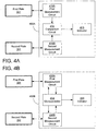
- FIGURE 4A shows a block diagram of a capacitive sensor having two primary plates 301 and 302 and associated circuitry 400A, in accordance with the present invention.
- a sensor includes a first plate 301, a second plate 302 and electronic circuitry 400A having a first measurement circuit 410A, a second measurement circuit 410B, a comparison circuit 414, and an indicator 416.
- the first and second plates 301 and 302 are conventionally charged and discharged by the respective first and second measurement circuits 410A, 410B.
- Each measurement circuit 410A, 410B provides a capacitance measurement to the comparison circuit 414.
- the capacitance measurement may be an indication of a change in capacitance from a nominal capacitance experienced during calibration.
- the comparison circuit 414 processes the capacitance measurements. For example, the comparison circuit 414 may compute a ratio between the capacitive measurements.
- the comparison circuit 414 may determine whether the capacitive measurements are within a predetermined value of each other.
- the comparison circuit 414 may determine whether one of the capacitive measurements is above or below a threshold, thereby determining a depth feature of an object, e.g., whether the object, such as a stud, is far or near to the surface.
- the comparison circuit 414 then provides a signal to the indicator 416.
- the indicator 416 may be used to alert the operator of information regarding an object, such as a stud.
- the indicator 416 may identify a detection of, for example, an edge of an object, a center of an object, or that the sensor is over an object, or the sensor is approaching an object.
- the indicator 416 may provide a direction of increasing capacitance, thereby informing an operator as to which direction to move the sensor.
- the indicator 416 may also provide an indication of whether the object is near or far/deep from the surface.
- the comparison circuit 414 may compare and/or process the capacitance measurements to determine whether an object or a discontinuity is present and/or whether a feature of an object or a discontinuity is detected. For example, comparison circuit 414 may determine that the sensor 300 is centered over a stud 100 by detecting that the capacitance measurements are equal to each other and also above a floor threshold. Capacitance measurements may be considered equal when they are within a predetermined percentage value or absolute value from each other.
- Comparison circuit 414 may determine that the sensor is centered over an edge 102 of a stud 100 by detecting that the capacitance measurements form a ratio that is equal to a transition ratio.
- the transition ratio may be a fixed value, a value indirectly or directly selected by a user, a value extracted from a lookup table or a computed value.
- a capacitance ratio may be considered equal to the transition ratio when the capacitance ratio falls within range of values about the transition ratio.
- the comparison circuit 414 couples capacitance measurement to the indicator 416.
- the indicator 416 may visually (or audibly) display a value indicative of each capacitance value.
- the operator may use the displayed values to visually determine whether an object or a discontinuity exists, for example, by looking for changing capacitive measurements. Additionally, an operator may use the displayed values to visually determine the location of edges 102 and centerlines 101 of studs 100, for example, by looking for capacitance measurements equaling a transition ratio.
- FIGURE 4B shows another version of a sensor having two primary plates 301 and 302 and circuitry 400B.
- the sensor includes a first plate 301, a second plate 302 and electronic circuitry 400B having a first measurement circuit 420A, a second measurement circuit 420B, a properly programmed microcomputer or a microcontroller 424, and an indicator 426.
- microcontroller 424 carries out the comparator functions of comparison circuit 414 of FIGURE 4A .
- the first and second plates 301 and 302 are charged and discharged by the respective first and second measurement circuits 420A, 420B.
- Each measurement 402A, 402B circuit provides a capacitance measurement to the microcontroller 424.
- the microcontroller 424 may provide timing or other control signals to the first and second measurement circuits 420A and 420B.
- the microcontroller 424 processes the capacitance measurements and may provide a signal to the indicator 426.
- the indicator 416 may include a display, such as a liquid crystal display and/or LEDs, and may include an audio device, such as a speaker or buzzer.
- a ratiometric capacitive sensor 300 in accordance with the invention may be used to detect a variety of hidden objects in addition to studs and joists. For example, a sensor having long and narrow plates may be used to find a crack or gap hidden behind a surface. Sensor 300 may be used to find a safe hidden behind a wall. Sensor 300 may be used to find brick wall hidden behind sheetrock. Additionally, sensor 300 may be stationary and be positioned to allow objects with hidden features to pass across its plates.
Landscapes
- Physics & Mathematics (AREA)
- Engineering & Computer Science (AREA)
- Remote Sensing (AREA)
- Life Sciences & Earth Sciences (AREA)
- Electromagnetism (AREA)
- Environmental & Geological Engineering (AREA)
- Geology (AREA)
- General Life Sciences & Earth Sciences (AREA)
- General Physics & Mathematics (AREA)
- Geophysics (AREA)
- Measurement Of Length, Angles, Or The Like Using Electric Or Magnetic Means (AREA)
- Geophysics And Detection Of Objects (AREA)
Description
- This invention relates to an electronic sensor, and, in particular, to a sensor suitable for detecting the location of an object behind a variety of surfaces, such as walls, floors and other non-electrically conductive structures (but not limited to building structures). More specifically, the invention relates to an electronic sensor useful to detect centerlines and edges of wall studs, floor joists, and the like.
-
U.S. Patent No. 4,464,622 entitled "Electronic wall stud sensor," issued Aug. 7, 1984, discloses an electronic wall stud sensor particularly suitable for locating a stud positioned behind a wall surface. (A "stud" is a structural member of a building to which an interior wall surface such as wall board or paneling is affixed.) Typically in the U.S., "2-by-4" wooden studs are used in construction. Nominally, a 2-by-4 stud is 51 mm (2 inches) wide and 102 mm (4 inches) deep and of any suitable length. The actual dimensions of a 2-by-4 are more typically 38 mm (1 ½ inches) wide and 89 mm (3 ½ inches) deep. Use of English (inches) units and U.S. stud sizes here is in conformance with U.S. construction practice and is not intended to be limiting, but is only illustrative. Finding studs is a typical problem for building repairs, picture hanging, etc. - The sensor detects the stud by measuring a change in capacitance due to a change in the dielectric constant along the wall. Due to the placement of the studs, a wall surface exhibits changing dielectric constants while the sensor is moved along the wall surface. The sensor includes a plurality of capacitor plates, a circuit for detecting changes in the capacitance, and an indicator.
- The plurality of capacitor plates is mounted in the sensor such that they can be positioned close to a wall's surface. When the capacitor plates are drawn along the surface, the circuit detects a change in the capacitance of the plates due to a change in the average dielectric constant of the surface. The capacitor plates are used to measure the effective capacitance or change in capacitance of a wall. Before detection begins, the sensor first performs a calibration to null out the effect of a wall in the absence of a stud.
- The capacitor plates are composed of a center plate and a symmetric pair of electrically connected edge plates. A difference in capacitance between the center and edge plates is used to determine the location of the edge of a stud. The centerline of the stud is then determined by finding both the left and right edges of the stud and then measuring to the middle of the distance between the edges. Thus, multiple measurements must be made in order to determine the centerline of the stud. The indicator indicates a change in capacitance of the capacitor plate, thereby alerting an operator to the wall stud position. The indicator also alerts the operator when calibration is occurring.
- While this procedure is effective in determining the centerline of a stud, significant errors in determining the location of the stud's edges can occur. One factor is the depth of the stud behind the surface. Due to the thickness of the sheetrock (also referred to as gypsum wall board and which has a thickness of 16 mm or equivalently 5/8 of an inch) or other wall surface material, a "ballooning" effect may distort the perceived width of the stud. The closer a stud is positioned to the surface, the wider the stud will appear when sensed in this way. Similarly, the farther or deeper a stud is positioned, the narrower the stud will appear. This ballooning effect is exacerbated when the sensitivity of the sensor is increased to aid in detecting deeper studs. The ballooning may be asymmetric due to electrical wires, metallic pipes and other objects in close proximity to the stud, which in turn may lead to a reduced ability to accurately determine a stud's centerline. In the case of extreme ballooning, location of an edge of a stud can be inaccurately indicated by as much as 51 mm (2 inches). Similarly, the centerline of the stud may be so inaccurately indicated that it is completely off the actual stud location.
- A first method of compensating for the ballooning effect is shown in
U.S. Patent No. 6,023,159 , entitled "Stud sensor with dual sensitivity," issued February 8, 2000. Unfortunately, using a dual sensitivity control only partially minimizes the ballooning effect. - A second method of compensating for the ballooning effect is shown in
U.S. Patent No. 5,917,314 , entitled "Electronic wall-stud sensor with three capacitive elements," issued June 29, 1999. This second method discloses using three parallel sensing plates and using sums and differences between the various plate capacitances to determine the centerline and edges of a stud. - The above methods, which use electronic wall stud sensors, are unable to reliably and accurately sense an edge of a stud (or other structural member) through surfaces that are thicker than 38 mm (1 ½ inches). Additionally, these sensors, if overly sensitive, falsely indicate the presence of non-existing studs. Therefore, known sensors have disadvantages.
-
US 5917314 describes a device for locating the edges of wall studs including a comparison circuit connected to each of three capacitive elements. As the device is moved along a wall, the comparison circuit monitors the relative charge time associated with each capacitive element, the charge times providing an indication of the relative capacitances of the three capacitive elements. Changes in the relative capacitances of the three elements as the device is moved along a wall are due to a change in the dielectric constant of the wall, which normally results from the presence of a wall stud behind the surface over which the device is moved. The comparison circuit uses differences in the measured relative capacitances of the first, second, and third capacitive elements to locate the edges of the stud. - An apparatus and method for determining a feature of a member located behind a surface while reducing effects of an unknown thickness of the member are provided. The feature is a centerline of a building object or member, such as a stud or joist but is not so limited. The sensor apparatus includes a plurality of capacitive plates.
- One aspect of the invention provides method of finding a feature behind a surface according to
claim 1. - A second aspect of the invention provides a sensor for finding a feature of a structure according to claim 19.
- The sensor may also include circuitry to sense an effective capacitance created by a plate, the covering and objects behind the covering. The sensor may compute a ratio between the capacitance measurements of a pair of the plates. A ratio of approximately one may indicate a centerline of a stud or joist or similar member. A ratio in a predetermined range may indicate an edge of a stud or joist. Additionally, the sensor may analyze a capacitance measurement to determine a depth of the feature.
- Some embodiments of the invention provide a method of finding a feature behind a surface using a sensor having a first plate and a second plate of approximately equal areas, the method comprising the acts of: moving the sensor and surface adjacent one another; measuring a first capacitance of a first capacitor including the first plate and the feature; measuring a second capacitance of a second capacitor including the second plate and the feature; comparing the first capacitance measurement to the second capacitance measurement; comparing one of the first or second capacitance measurements with a first threshold; and repeating the acts of measuring and comparing.
- Some embodiments of the invention provide a sensor for finding a feature of a structure comprising: a first plate having a first capacitance and adapted for forming a first capacitor with the structure; a second plate having a second capacitance and adapted for forming a second capacitor with the structure; a first measurement circuit coupled to the first plate, the first measurement circuit measuring a first capacitance value of the first capacitor; a second measurement circuit coupled to the second plate, the second measurement circuit measuring a second capacitance value of the second capacitor; and a comparison circuit coupled to the first and second measurement circuits, the comparison circuit generating a ratio of the first and second capacitance values and comparing one of the first or second capacitance values to a first threshold.
- Some embodiments of the invention provide a sensor comprising: a first plate and a second plate positioned in about the same plane and spaced apart, and adapted to be located adjacent a surface; a measurement circuit coupled to the first and second plates thereby to measure a capacitance value of each of the plates; a first comparison circuit coupled to receive the measured capacitance values and determine a ratio between a change in the measured capacitance values; and a second comparison circuit coupled to receive one of the measured capacitance values and a threshold and to provide a comparison therebetween.
- Other features and aspects of the invention will become apparent from the following detailed description, taken in conjunction with the accompanying drawings which illustrate, by way of example, the features in accordance with embodiments of the invention. The summary is not intended to limit the scope of the invention, which is defined solely by the claims attached hereto.
-
-
FIGURES 1A-1D illustrate a plan view of and capacitance produced by a ratiometric capacitive sensor having two primary plates, in accordance with the present invention, positioned at a lateral distance away from an object, such as a hidden stud. -
FIGURES 2A-2C show a sensor centered over studs and a graph of capacitance measurements of two primary plates versus a lateral distance between a sensor and a shallow object and a deep object, such as hidden studs, in accordance with the present invention. -
FIGURE 3 illustrates a process to indicate whether or not a depth feature of an object, such as a stud, has been detected, in accordance with the present invention. -
FIGURES 4A and 4B each show a block diagram of a capacitive sensor having two primary plates and circuitry, in accordance with the present invention. - In the following description, reference is made to the accompanying drawings which illustrate several embodiments of the present invention. It is understood that other embodiments may be utilized and mechanical, compositional, structural, electrical, and operational changes may be made without departing from the scope of the present disclosure. The following detailed description is not to be taken in a limiting sense, and the scope of the embodiments of the present invention is defined only by the claims of the issued patent.
- Some portions of the detailed description which follows are presented in terms of procedures, steps, logic blocks, processing, and other symbolic representations of operations on data bits that can be performed on computer memory. A procedure, computer executed step, logic block, process, etc. , are here conceived to be a self-consistent sequence of steps or instructions leading to a desired result. The steps are those utilizing physical manipulations of physical quantities. These quantities can take the form of electrical, magnetic, or radio signals capable of being stored, transferred, combined, compared, and otherwise manipulated in a computer system. These signals may be referred
to at times as bits, values, elements, symbols, characters, terms, numbers, or the like. Each step may be performed by hardware, software, firmware, or combinations thereof. - This application relates to
U.S. Patent Application No. 10/794,356 filed March 4, 2004 - A ratiometric capacitive sensor may use capacitance measurements from multiple conductive plates to determine the presence of objects, such as studs and joists, hidden behind a covering surface such as a wall, floor, ceiling, etc. In some embodiments, a ratiometric capacitive sensor includes two conductive plates. Each conductive plate acts as part of a separate capacitor. Circuitry coupled to each plate measures an effective change in capacity of the separate capacitors, which is effected by the density of material in close proximity to the plates. As a result, a wall or other surface covering combined with an underlying stud or other member form a larger capacitance than a wall covering alone without a stud. A capacitance measurement may be taken from each plate. The capacitance measurement from one plate may then be compared to a capacitance measurement of another plate to determine boundaries and features of the materials in the vicinity of the plates.
-
FIGURE 1A illustrates a plan view of acapacitive sensor 300 having twoprimary plates sensor 300 is positioned against awall 99 at a lateral distance D away from a hiddenstud 100A. A wall may have multiple studs 100 (e.g., 100A, 100B and 100C). Eachstud 100 has twoedges 102 and defines acenterline 101 relative to its positioning along thewall 99. Additionally,sensor 300 defines acenterline 304 that may be equally positioned between afirst plate 301 and asecond plate 302. In some embodiments, associated circuitry and/or software (not shown) operates to independently measure values indicative of a capacitance of eachplate -
FIGURES 1B and 1C illustrate a capacitance produced between eachrespective plate sensor 300 and thewall 99.FIGURE 1B shows acapacitance curve 310 produced by thefirst plate 301 and thewall 99.FIGURE 1C shows acapacitance curve 320 produced by thesecond plate 302 and thewall 99. Capacitance curves 310 and 320 are drawn relative to thecenterline 304 of thesensor 300. Additionally, curves 310 and 320 show peaks whenrespective plates centerline 101 of astud 100 and show valleys whenrespective plates studs 100. - At points where a
sensor 300 measures a minimum capacitance valve or a relatively low capacitance valve,sensor 300 may be positioned far from anystud 100. The measured capacitance values increase as thesensor 300 nears thestud 100; however, the capacitance values of eachplate stud 100. For example, afirst plate 301 may be close to or over anedge 102 of astud 100. At the same time, thesecond plate 302 may still be positioned at a lateral distance away from thestud 100. In this case, the change in capacitance from its minimum value experienced by thefirst plate 301 will be greater than the change in capacitance experienced by thesecond plate 302. - In some embodiments, the capacitance measurements are used to calculate a ratio. A first capacitance measurement represents the change in capacitance from a calibration value experienced on a
first plate 301. A second capacitance measurement represents the change in capacitance from a calibration value experienced on asecond plate 302. A ratio between the first and second capacitance measurements may be computed. If the ratio is approximately equal to a determined value, it may be realized that acenterline 304 of thesensor 300 is centered over anedge 102 of astud 100. If the capacitance measurements are equal or the ratio is approximately equal to unity, both plates may be centered over the stud'sedge 102 and thecenterline 304 of thesensor 300 may be centered over thecenterline 101 of thestud 100. - FIGURE ID shows overlapping first and second capacitance curves 310 and 320 relative to the
centerline 304 of thesensor 300 and astud 100. A point at which curves 310 and 320 intersect may indicate a position of thesensor 300 where each plate is encountering an equal capacitance; therefore, thecenterline 304 of thesensor 300 may be directly over acenterline 101 of thestud 100. In some embodiments, at least one of the capacitance values must be above a floor threshold value, a value above a calibration capacitance value, before the capacitance measurements are compared with each other. - FIGURE IE shows a graph of a
curve 330, which represents a ratio of capacitance measurements of twoprimary plates centerline 304 and acenterline 101 of astud 100, in accordance with the present invention. This ratio may be computed as the smaller capacitance divided by the larger capacitance, thereby resulting in a ratio that is equal to or less than one. - The calculated results, shown in a
ratio curve 330, exhibits a sharp peak. The sharp peak ofcurve 330 allows a ratiometric sensor to locate a stud'scenterline 101 with increased accuracy over non-ratiometric sensor, which may generate rounded peaked curves. - Additionally, a transition ratio may be compared to the calculated ratio to determine the location of an
edge 102 of astud 100 as further described below. The transition ratio predicts a capacitance ratio formed at an edge of a stud when thesensor 300 is centered over the stud's edge for a particular wall structure. As such, a transition ratio may be used to indicate when thesensor 300 is centered over anedge 102. - A transition ratio may be determined in a number of ways. The transition ratio may be a factory set constant. Alternatively, the transition ratio may be set by an operator. In some embodiments, the transition ratio is calculated during operation.
- In some embodiments, a transition ratio may be set during manufacturing as a factory set constant. For example, a factory may set a transition ratio equal to a fixed value, e.g., 0.33. When plates produce capacitance measurements that form a ratio approximately equal to 0.33,
sensor 300 may indicate that the center ofsensor 300 is directly over anedge 102 ofstud 100. - In some embodiments, a transition ratio may be directly or indirectly selected by an operator of the sensor. For example, an operator may select a stud width and/or a wall thickness. The stud width and/or wall thickness may be used to select an appropriate transition ratio, for example, as shown in the table below.
Stud Type Wall Covering Thickness Transition Ratio Double stud 76 mm (3 inches) Single sheet 13 mm (½ an inch) 0.32 Single stud 38 mm (1 ½ inches) Single sheet 13 mm (½ an inch) 0.33 Double stud 76 mm (3 inches) Double sheet 25 mm (1 inch) 0.35 Single stud 38 mm (1 ½ inches) Double sheet 25 mm (1 inch) 0.45 - In some embodiments, a transition ratio may be automatically determined by the
sensor 300 based on capacitance measurements. A capacitance measurement may be a measure of a maximum capacitance measurement on a plate as shown inFIGURE 3 . - In some circumstances, the actual ratio of measured plate capacitances at the stud's
edge 102 varies predictably with the wall thickness. Therefore, a maximum measured capacitance value may be used to set a transition ratio used to locate a stud's edge. This maximum value may indicate a wall covering's thickness, with thicker walls having smaller maximum values. The maximum value may also provide an indication of the width of the stud, with wider studs having larger maximum values. The measured capacitance values may also be compared to indicate a direction of a stud with the plate having a higher capacitance measurement indicating the direction of the center of the stud. - In some embodiments, plate capacitance is measured by determining a time it takes to charge a
plate plate -
FIGURES 2A and 2B each illustrate a plan view ofcapacitive sensor 300 with thecenterline 304 centered directly over acenterline 101 of a hiddenstud 100, resulting in a center-to-center distance of D = 0. In this position, eachplate stud 100. Eachplate - A covering of wall (surface) 99 may be of different thicknesses. A thin wall covering will exhibit a low nominal capacitance, where as a thicker wall covering will exhibit a higher nominal capacitance. A stud positioned behind a thin wall covering will produce a high maximum capacitance. A stud position behind a thicker wall covering will be farther away from the wall's external surface and therefore will produce a lower maximum capacitance.
-
FIGURE 2C shows capacitance curves for twoplates sensor 300 that has been pulled across awall 99. As asensor 300 passes over afirst stud 100A,sensor 300 measures capacitances shown oncurves respective plates sensor 300 passes over asecond stud 100B,sensor 300 measures lower capacitance values as shown incurves -
Sensor 300 may compare capacitance measurements to a depth threshold. For example, whensensor 300 is positioned over an edge of a stud, a center of a stud, or between edges of a stud,sensor 300 may indicate whether or not the detected stud is a deep stud or not a deep stud. The indication may be an audio indication, such as from a buzzer insensor 300, a visual indication, such as from an LED, a signal level, such as supplied to a control line, or any combination thereof. - The indication of a depth of a feature may be used by the sensor operator. For example, if most features are determined to originate from a non-deep stud, the operator may conclude that deep features are anomalies. Similarly, if most features are determined to be deep, then any non-deep features may be ignored by the operator.
- Assuming
stud 100A is positioned at a first distance behind a wall's surface andstud 100B is positioned at a farther distance behind the wall's surface, each stud will produce a different capacitance measurement whensensor 300 is centered over the stud. For example, whensensor 300 is centered overstud 100A, DAC counts of 80 above calibration values on each plate may result. Whensensor 300 is centered overstud 100B, DAC counts of 30 above the calibration values on each plate may result. - Plates producing equal measurements above a floor threshold indicate that the sensor is centered over the stud. Additionally, a higher DAC count indicates that the stud is closer to the surface, the stud is wider than a reference stud and surface, or a material of higher conductivity is detected. An example DAC count of 80 may represent that a single-width stud is positioned behind a single-layer of sheetrock. An example DAC count of 30 may represent that a single-width stud is positioned behind a double-layer of sheetrock.
- In some embodiments, a transition ratio may be calculated by
sensor 300 based on a historic maximum capacitance measurement. In other embodiments, the transition ratio may be calculated based on an instantaneous maximum capacitance measurement. - A historic maximum capacitance measurement may be determined over time as measured from either
plate plate sensor 300. As the capacitance changes over time, an updated maximum capacitance value may be stored. - Alternatively, a capacitance measurement may be used. A capacitance measurement may be selected each time the
sensor 300 takes each pair of capacitance measurements fromplates 
- In other embodiments, the instantaneous capacitance value may be determined by examining the capacitance formed by a
single plate 301. In some embodiments, the instantaneous capacitance value is determined over a period of time, e.g., by a moving average or the like. - Using the capacitance measurement, the
sensor 300 may select a transition ratio from a table or compute a transition ratio from a formula. Asensor 300, having plates centered 38 mm (1 ½ inches) apart, with each plate 19 mm (¾ of an inch) wide, may use a transition ratio as shown in the table below. For example, a capacitance measurement of 1.4, representing a double-width stud hidden behind a single sheet of sheetrock, may have a transition ratio of 0.32. A lookup table in the memory ofsensor 300 may be used to map a capacitance measurement to a transition ratio.Capacitance Measurement Transition Ratio 1.4 0.32 1.0 0.33 0.6 0.35 0.4 0.45 - Alternatively, the
sensor 300 may compute a transition ratio for each ratio calculation. In some embodiments, a transition ratio may be calculated as:
- Once determined, the transition ratio may be used to indicate whether the sensor is centered over an edge of a stud.
Sensor 300 may measure a first capacitance value on afirst plate 301 and a second capacitance value on asecond plate 302. A capacitance ratio may be calculated between the first and second capacitance values. This capacitance ratio may be compared to the predicted transition ratio to determine whether thesensor 300 is presently centered over anedge 102 of astud 100. - For example,
sensor 300 measuring a larger capacitance value of 1.4 may indicate thesensor 300 has passed over a double-wide stud having a width of 76 mm (3 inches) hidden behind a single layer of sheetrock having a thickness of 13 mm (½ an inch). The transition ratio for this wall structure may be set to a value of 0.32. When thesensor 300 detects a position where the first and second capacitance measurements are approximately equal to 0.32, thesensor 300 may indicate that thesensor 300 is centered over anedge 102. In some embodiments, the stud's edge location may be determined to an accuracy of approximately 3 mm (1/8 of an inch) over a wall covering thickness range of 13 to 25 mm (½ to 1 inch). - Measured capacitance values indicate a direction in which a
stud 100 is located. At a stud'sedge 102, one plate may be directly over thecenterline 101 of thestud 100, while the other may be off to one side of thestud 100. Theplate stud 100 will have a larger capacitance than theother plate sensor 300 is drawn across thestud 100. Aplate centerline 304 of thesensor 300 needs to be moved in the direction of thatplate - A
ratio curve 330 may be computed as follows. When thefirst plate 301 produces a capacitance that is greater than the capacitance produced by thesecond plate 302, a ratio is calculated by dividing the second plate's change in capacitance value by the larger first plate's change in capacitance value. Similarly, when thefirst plate 301 produces a capacitance that is less than the capacitance produced by thesecond plate 302, the ratio is calculated by dividing the smaller first plate's change in capacitance value by the second plate's change in capacitance value. Formulaically, theratio curve 330 may be computed by:
plate -
FIGURE 3 illustrates a process to indicate whether or not a depth feature of an object has been detected, in accordance with the present invention as carried out by a computer program executed by a processor resident in the sensor. The order of steps presented may be rearranged by those of ordinary skill in the art and coding such a program is well within the skill of one of ordinary skill in the art in light of this disclosure. Further, the steps of this process may conventionally be undertaken by conventional circuitry or the computer program or by a combination thereof. - At
step 700, asensor 300 powers up and maybe positioned against asurface 99.Sensor 300 performs acalibration step 710 to reduce the impact of parasitic circuit and wall capacitances. The calibration step determines a calibration capacitance such as a DAC value that represents an absolute capacitance of a plate over the wall structure and includes parasitic capacitances of thesensor 300. - At
step 720,sensor 300 begins a process of measuring plate capacitances, e.g., determining capacitance measurements in the form of a relative capacitance values from the calibration capacitance values. Atstep 730, thesensor 300 computes a capacitance ratio between plate capacitance measurements fromstep 720. - At
step 740, asensor 300 determines whether the capacitive measurements ofstep 720 indicate acenterline 101 of an object or a discontinuity has been detected. That is, if the capacitance ratio is approximately equal to unity, or alternatively, if the capacitance measurements are approximately equal to one another. If not, the process may continue to step 770. If so, atstep 750,sensor 300 may provide a visual and/or an audio indication that acenterline 101 of the object or the discontinuity is detected. - At
step 760,sensor 300 determines whether the detected center is a deep feature. A deep feature may be determined by comparing one or more of the measured plate capacitances (from step 720) with a threshold value such as depth threshold indicated inFIGURE 2C . If a deep feature is not detected,sensor 300 repeats the process withstep 720. If a deep feature is detected, atstep 765,sensor 300 may provide an indication that a deep feature was detected. - At
step 770,sensor 300 determines a transition ratio. Atstep 780,sensor 300 compares the computed capacitance ratio to the determined transition ratio. That is,sensor 300 determines whether the capacitive measurements ofstep 720 indicate that an edge of an object or a discontinuity has been detected. An edge is detected when the capacitance ratio is approximately equal to a transition ratio. If not,sensor 300 repeats the process withstep 720. If so, atstep 790,sensor 300 provides a visual and/or an audio indication that an edge of the object or the discontinuity is detected. Asensor 300 then determines whether the detected edge is a deep feature as described withstep 760 above. - Additionally,
sensor 300 may determine a relative direction an object or a discontinuity exists based on the relative magnitudes of the measured plate capacitances. For example, thesensor 300 indicates that the stud is positioned to the left of thecenterline 304 of thesensor 300.Sensor 300 indicates the direction of an object or a discontinuity audibly and/or visually. - In operation, an operator or user may pass
sensor 300 acrosswall 99. If each stud feature is detected as not being associated with a deep stud except for one stud, the operator may use the deep indication as a warning and conclude the deep feature is an anomaly. - Similarly, if an operator discovers all stud features are associated with deep studs except for one non-deep stud, the operator may conclude that the non-deep stud is an anomaly. For example, a wall may have all wood studs and some metallic wiring. The wood studs, if behind two or three layers of sheetrock, may appear as deep studs. The metal wiring may appear as a shallow stud. The operator may conclude that the indication of a shallow stud was erroneous.
- An apparatus in accordance with the present invention may have features implemented in hardware, software or a combination of hardware and software. Thus, blocks described with reference to the following figures may be implemented in hardware, software, firmware, dedicated circuitry, and/or programmable circuitry, or a combination thereof.
-
FIGURE 4A shows a block diagram of a capacitive sensor having twoprimary plates circuitry 400A, in accordance with the present invention. In some embodiments, a sensor includes afirst plate 301, asecond plate 302 andelectronic circuitry 400A having afirst measurement circuit 410A, asecond measurement circuit 410B, acomparison circuit 414, and anindicator 416. The first andsecond plates second measurement circuits - Each
measurement circuit comparison circuit 414. The capacitance measurement may be an indication of a change in capacitance from a nominal capacitance experienced during calibration. Thecomparison circuit 414 processes the capacitance measurements. For example, thecomparison circuit 414 may compute a ratio between the capacitive measurements. Thecomparison circuit 414 may determine whether the capacitive measurements are within a predetermined value of each other. Thecomparison circuit 414 may determine whether one of the capacitive measurements is above or below a threshold, thereby determining a depth feature of an object, e.g., whether the object, such as a stud, is far or near to the surface. - The
comparison circuit 414 then provides a signal to theindicator 416. Theindicator 416 may be used to alert the operator of information regarding an object, such as a stud. Theindicator 416 may identify a detection of, for example, an edge of an object, a center of an object, or that the sensor is over an object, or the sensor is approaching an object. Theindicator 416 may provide a direction of increasing capacitance, thereby informing an operator as to which direction to move the sensor. Theindicator 416 may also provide an indication of whether the object is near or far/deep from the surface. The comparison circuit 414 (e.g., a comparator) may compare and/or process the capacitance measurements to determine whether an object or a discontinuity is present and/or whether a feature of an object or a discontinuity is detected. For example,comparison circuit 414 may determine that thesensor 300 is centered over astud 100 by detecting that the capacitance measurements are equal to each other and also above a floor threshold. Capacitance measurements may be considered equal when they are within a predetermined percentage value or absolute value from each other. -
Comparison circuit 414 may determine that the sensor is centered over anedge 102 of astud 100 by detecting that the capacitance measurements form a ratio that is equal to a transition ratio. The transition ratio may be a fixed value, a value indirectly or directly selected by a user, a value extracted from a lookup table or a computed value. A capacitance ratio may be considered equal to the transition ratio when the capacitance ratio falls within range of values about the transition ratio. - In some embodiments, the
comparison circuit 414 couples capacitance measurement to theindicator 416. Theindicator 416 may visually (or audibly) display a value indicative of each capacitance value. The operator may use the displayed values to visually determine whether an object or a discontinuity exists, for example, by looking for changing capacitive measurements. Additionally, an operator may use the displayed values to visually determine the location ofedges 102 andcenterlines 101 ofstuds 100, for example, by looking for capacitance measurements equaling a transition ratio. -
FIGURE 4B shows another version of a sensor having twoprimary plates circuitry 400B. The sensor includes afirst plate 301, asecond plate 302 andelectronic circuitry 400B having afirst measurement circuit 420A, asecond measurement circuit 420B, a properly programmed microcomputer or amicrocontroller 424, and anindicator 426. Heremicrocontroller 424 carries out the comparator functions ofcomparison circuit 414 ofFIGURE 4A . - The first and
second plates second measurement circuits microcontroller 424. Additionally, themicrocontroller 424 may provide timing or other control signals to the first andsecond measurement circuits microcontroller 424 processes the capacitance measurements and may provide a signal to theindicator 426. Theindicator 416 may include a display, such as a liquid crystal display and/or LEDs, and may include an audio device, such as a speaker or buzzer. - A
ratiometric capacitive sensor 300 in accordance with the invention may be used to detect a variety of hidden objects in addition to studs and joists. For example, a sensor having long and narrow plates may be used to find a crack or gap hidden behind a surface.Sensor 300 may be used to find a safe hidden behind a wall.Sensor 300 may be used to find brick wall hidden behind sheetrock. Additionally,sensor 300 may be stationary and be positioned to allow objects with hidden features to pass across its plates. - While the present invention has been described with reference to one or more particular variations, those skilled in the art will recognize that many changes may be made thereto without departing from the scope of the present invention. Each of these embodiments and obvious variations thereof are contemplated as falling within the scope of the claimed invention, which is set forth in the following claims.
Claims (30)
- A method of finding a feature (100) behind a surface (99) using a sensor (300) having first and second plates (301, 302), the method comprising the acts of:moving the sensor (300) and surface (99) adjacent one another;measuring (720) a first capacitance of a first capacitor including the first plate (301) and the feature (100);measuring (720) a second capacitance of a second capacitor including the second plate (302) and the feature (100); characterized bycomputing (730) a ratio of the first and second capacitance measurements to determine a centerline of the feature (100) relative to the first and second plates (301; 302); andcomparing one of the first or second capacitance measurements with a first threshold, thereby to determine a depth of the feature (100) relative to the surface (99), wherein the act of comparing one of the first or second capacitance measurements with the first threshold includes:determining a largest capacitance measurement of the first or second capacitance measurements; anddetermining (765) the feature (100) is deep if the largest capacitance measurement is less than the first threshold.
- A method according to claim 1, further comprising repeating the acts of measuring and comparing.
- The method of claim 1, further comprising the act of determining whether the ratio is within a predetermined range, indicating that an edge (102) of an object behind the surface (99) is detected.
- The method of any one of claims 1 to 3, further comprising the acts of:determining a first reference that represents an initial capacitance of the first capacitor; anddetermining a second reference that represents an initial capacitance of the second capacitor.
- The method of claim 4, wherein:the first capacitance measurement is a difference between the first reference and the first capacitance measurement; andthe second capacitance measurement is a difference between the second reference and the second capacitance measurement.
- The method of any one of claims 1 to 5, further comprising the acts of:determining whether one or more of the first and second capacitance measurements is greater than or equal to the first threshold; andrepeating measurement of the first and second capacitances if one or more of the first and second capacitance measurements is greater than or equal to the first threshold.
- The method of claim 3, wherein a denominator of the ratio is a maximum of the first and second capacitance measurements.
- The method of claim 3, wherein the predetermined range is a range having fixed limits.
- The method of claim 1, further including indicating the feature (100) is deep if the one of the first or second capacitance measurements is less than the first threshold.
- The method of claim 1, further including indicating the feature is not deep if the one of the first or second capacitance measurements is greater than the first threshold.
- The method of claim 1, further comprising the acts of:comparing the first and second capacitance measurements;determining that an edge (102) of an object behind the surface (99) is closer to a centerline (304) of the first plate (301) than a centerline of the second plate if the first capacitance measurement is greater than the second capacitance measurement; anddetermining that the edge (102) is closer to the centerline of the second plate (302) than the centerline of the first plate (301) if the first capacitance measurement is less than the second capacitance measurement.
- The method of any one of the preceding claims, further comprising the acts of determining whether the ratio is within a predetermined range of a value of one, and if so indicating that the centerline (101) is detected.
- The method of claim 12, wherein the predetermined range is inclusively 0.9 to 1.
- The method of any one of the preceding claims, wherein the first and second capacitances are indicative of a duration of time necessary to charge a respective one of the first and second plates (301, 302) to a respective reference level.
- The method of claim 4, wherein:the first reference is indicative of a duration of time necessary to charge the first plate (301) having the initial capacitance to a first reference;the second reference is indicative of a duration of time necessary to charge the second plate (302) having the initial capacitance to a second reference;wherein the first capacitance is a difference between the first reference and a duration of time to charge the first plate (301) to the first reference; andthe second capacitance is a difference between the second reference and a duration of time to charge the second plate (302) to the second reference.
- The method of claim 4, wherein:the first reference is indicative of a first voltage necessary to charge the first plate (301) having the initial capacitance to a first reference within a determined time;the second reference is indicative of a second voltage necessary to charge the second plate (302) having the initial capacitance to a second reference within the determined time;wherein the first capacitance measurement is a difference between the first reference and an indication of the first voltage; andwherein the second capacitance measurement is a difference between the second reference and an indication of the second voltage.
- The method of any one of the preceding claims, the act of moving comprising applying the sensor (300) to the surface (99), or applying the surface (99) to the sensor (300).
- The method of any one of the preceding claims, wherein the act of comparing the first and second capacitance measurements includes:determining whether the first and second capacitance measurements are equal;indicating that, if the first and second capacitances are equal, the centerline (101) is detected.
- A sensor (300) for finding a feature (100) behind a surface (99), comprising:a first plate (301) having a first capacitance and adapted for forming a first capacitor with the structure;a second plate (302) having a second capacitance and adapted for forming a second capacitor with the structure;a first measurement circuit (410A) coupled to the first measurement circuit (410A) measuring a first capacitance value of the first capacitor;a second measurement circuit (410B) coupled to the second plate (302), the second measurement (410B) circuit measuring a second capacitance value of the second capacitor;a comparison circuit (414) coupled to the first and second measurement circuits (410A; 410B), characterized by the comparison circuit (414) generating a ratio of the first and second capacitance values to determine a centerline of the feature (100) relative to the first and second plates (301, 302) and comparing one of the first or second capacitance values to a first threshold to determine a depth of the feature (100) relative to the surface (99);threshold circuitry coupled to first and second measurement circuits (410A; 410B) and configured for determining whether the first and second capacitance values are below the first threshold to determine (760) if the feature (100) is deep.
- The sensor according to claim 19, wherein the first plate (301) and the second plate (302) are positioned in about the same plane and spaced apart and adapted to be located adjacent a surface (99), the comparison circuit (414) configured to:determine a change in the measured capacitance values;compute a ratio between the change in the measured capacitance values; andcompare the measured capacitance values with the first threshold.
- The sensor of claim 19 or 20, wherein:the first capacitance value represents a difference between the first capacitance and an initial capacitance of the first capacitor; andthe second capacitance value represents a difference between the second capacitance and an initial capacitance of the second capacitor.
- The sensor of claim 19, wherein the comparison circuit further determines whether the first and second capacitance values are greater than or equal the first threshold to determine if the feature is not deep.
- The sensor of claim 19, further comprising a processing circuit coupled to the comparison circuit (414) and coupled to receive the ratio value, and to determine whether the ratio is within a predetermined range.
- The sensor of claim 23, further comprising an indicator (416) coupled to the comparison circuit (414) thereby to provide an indication of the ratio of the capacitances.
- The sensor of claim 23, wherein the indicator (416) is adapted to provide an indication that the sensor (300) is over an edge (102) of the structure when the ratio is within the predetermined range.
- The sensor of claim 23, wherein the indicator (416) is adapted to provide an indication that the sensor (300) is over a centerline (101) of a portion of the structure when the ratio is within the range of one.
- The sensor of claim 20, further comprising an indicator coupled to the second comparison circuit thereby to provide an indication of a depth of a feature behind the surface (99).
- The sensor of claim 25, further including a memory storing look-up table and coupled to the processing circuit, the look-up table having a transition ratio for the processing circuit, wherein the transition ratio is used to set the predetermined range.
- The sensor of claim 23, further comprising:a source of a reference voltage;wherein the first measurement circuit includes a first index, the first index indicating a number of clock cycles needed to charge the first plate (301) to the reference voltage level; andwherein the second measurement circuit includes a second index, the second index indicating a number of clock cycles needed to charge the second plate (302) to the reference voltage level.
- The sensor of claim 29, wherein the first and second measurement circuits respectively include:a current source coupled to a respective one of the first or second plates (301, 302);a discharge switch coupled to the respective one of the first or second plates (301, 302);a digital-to-analog converter (DAC) having an input terminal coupled to receive a data signal from the processing circuit and an output terminal; anda comparator having a first input terminal coupled to the respective one of the first or second plates (301, 302), a second input terminal coupled to the DAC, and an output terminal providing the output signal of the measurement circuit.
Applications Claiming Priority (2)
| Application Number | Priority Date | Filing Date | Title |
|---|---|---|---|
| US10/846,337 US7148703B2 (en) | 2004-05-14 | 2004-05-14 | Auto-deep scan for capacitive sensing |
| PCT/US2005/004586 WO2005114261A1 (en) | 2004-05-14 | 2005-02-11 | Auto-deep scan for capacitive sensing |
Publications (2)
| Publication Number | Publication Date |
|---|---|
| EP1745310A1 EP1745310A1 (en) | 2007-01-24 |
| EP1745310B1 true EP1745310B1 (en) | 2019-05-08 |
Family
ID=34960956
Family Applications (1)
| Application Number | Title | Priority Date | Filing Date |
|---|---|---|---|
| EP05713484.3A Expired - Lifetime EP1745310B1 (en) | 2004-05-14 | 2005-02-11 | Auto-deep scan for capacitive sensing |
Country Status (4)
| Country | Link |
|---|---|
| US (1) | US7148703B2 (en) |
| EP (1) | EP1745310B1 (en) |
| CA (1) | CA2562927C (en) |
| WO (1) | WO2005114261A1 (en) |
Families Citing this family (19)
| Publication number | Priority date | Publication date | Assignee | Title |
|---|---|---|---|---|
| US7495455B2 (en) * | 2002-06-28 | 2009-02-24 | Solar Wide Industrial Limited | Stud sensing device |
| US7116091B2 (en) * | 2004-03-04 | 2006-10-03 | Zircon Corporation | Ratiometric stud sensing |
| US7501836B2 (en) * | 2006-11-14 | 2009-03-10 | Avago Technologies Enterprise IP (Singapore) Pte. Ltd. | Apparatus and method for determining capacitance variation in an integrated circuit |
| US7839282B1 (en) * | 2006-12-27 | 2010-11-23 | The United States Of America As Represented By The United States Department Of Energy | Capacitance probe for detection of anomalies in non-metallic plastic pipe |
| US7504817B2 (en) * | 2007-03-28 | 2009-03-17 | Solar Wide Industrial Limited | Stud sensor |
| US7982450B2 (en) | 2008-02-13 | 2011-07-19 | Lanny S Smoot | Device and method allowing the detection and display of objects located behind an obscuring surface |
| WO2009111743A1 (en) | 2008-03-07 | 2009-09-11 | Milwaukee Electric Tool Corporation | Battery pack for use with a power tool and a non-motorized sensing tool |
| US9664808B2 (en) | 2009-03-06 | 2017-05-30 | Milwaukee Electric Tool Corporation | Wall scanner |
| US8476912B2 (en) * | 2010-03-04 | 2013-07-02 | Franklin Sensors, Inc. | Obscured feature detector and method |
| US8593163B2 (en) * | 2010-03-04 | 2013-11-26 | Franklin Sensors, Inc. | Surface-conforming obscured feature detector |
| US8669772B2 (en) * | 2010-03-04 | 2014-03-11 | Franklin Sensors, Inc. | Obscured feature detector housing |
| US8941393B2 (en) * | 2011-01-14 | 2015-01-27 | Cypress Semiconductor Corporation | Detection of a conductive object during an initialization process of a touch-sensing device |
| CN103302333B (en) * | 2012-03-15 | 2017-12-05 | 南京德朔实业有限公司 | Pillar for electric drill finds device laser leveler component |
| US20150177372A1 (en) * | 2013-12-19 | 2015-06-25 | David I. Poisner | MIR Two Dimensional Scanner |
| CN203981898U (en) * | 2014-07-17 | 2014-12-03 | 杭州巨星工具有限公司 | Wall bone sniffer |
| US10524592B2 (en) * | 2015-12-01 | 2020-01-07 | Black & Decker Inc. | Picture hanging device |
| US10908312B2 (en) * | 2016-06-24 | 2021-02-02 | Stanley Black & Decker Inc. | Systems and methods for locating a metal object |
| US9903975B1 (en) | 2016-11-16 | 2018-02-27 | Lanny Starkes Smoot | Device and method to detect and display objects behind an obscuring surface |
| US12493131B2 (en) * | 2024-04-02 | 2025-12-09 | Zircon Corporation | System and method for detecting objects behind an opaque surface |
Family Cites Families (41)
| Publication number | Priority date | Publication date | Assignee | Title |
|---|---|---|---|---|
| US3278843A (en) * | 1962-10-01 | 1966-10-11 | Hughes Aircraft Co | Thickness rate monitoring system for depositing dielectric films |
| US3662258A (en) * | 1969-09-16 | 1972-05-09 | Brunswick Corp | Device for locating nails beneath the surface of a bowling lane |
| US3704413A (en) * | 1970-01-07 | 1972-11-28 | Maurice E Blevins | Method of translating the location of a predetermined position on one side of a substantially nonferrous structural barrier of a building to an opposite side of said barrier |
| US3836848A (en) | 1970-01-07 | 1974-09-17 | M Blevins | Method of translating the location of a predetermined position on one side of a substantially nonferrous structural barrier of a building to an opposite side of said barrier |
| US3836846A (en) * | 1971-09-09 | 1974-09-17 | Monsanto Co | Ice detection apparatus employing microwave reflectance |
| US3893025A (en) * | 1974-02-01 | 1975-07-01 | Plosser George G | Apparatus for determining the distance to a concealed conductive structure |
| US4086528A (en) * | 1975-09-17 | 1978-04-25 | United Kingdom Atomic Energy Authority | Capacitive transducers |
| US4041382A (en) * | 1976-08-16 | 1977-08-09 | The Sippican Corporation | Calibrating a measurement system including bridge circuit |
| US4067225A (en) * | 1977-03-21 | 1978-01-10 | Mechanical Technology Incorporated | Capacitance type non-contact displacement and vibration measuring device and method of maintaining calibration |
| US4099118A (en) * | 1977-07-25 | 1978-07-04 | Franklin Robert C | Electronic wall stud sensor |
| US4130796A (en) * | 1977-12-07 | 1978-12-19 | Westinghouse Electric Corp. | Calibrating and measuring circuit for a capacitive probe-type instrument |
| US4322678A (en) * | 1978-10-30 | 1982-03-30 | Capots Larry H | Identification of materials using their complex dielectric response |
| US4464622A (en) * | 1982-03-11 | 1984-08-07 | Franklin Robert C | Electronic wall stud sensor |
| US4639666A (en) * | 1984-08-27 | 1987-01-27 | New Holland, Inc. | Metal detector sensitivity adjustment and test assembly |
| DE3433148C2 (en) * | 1984-09-10 | 1987-01-22 | Endress U. Hauser Gmbh U. Co, 7867 Maulburg | Arrangement for detecting spatial inhomogeneities in a dielectric |
| US4676100A (en) * | 1984-10-31 | 1987-06-30 | Berwind Corporation | Capacitance-type material level indicator |
| GB8607747D0 (en) * | 1986-03-27 | 1986-04-30 | Duracell Int | Device |
| US4847552A (en) * | 1987-07-07 | 1989-07-11 | The Boeing Company | Detection of electrically conductive materials beneath surface coatings employing eddy currents |
| US4868910A (en) * | 1988-02-16 | 1989-09-19 | White's Electronics, Inc. | Metal detector with microprocessor control and analysis |
| US4947116A (en) * | 1988-09-02 | 1990-08-07 | Hamilton Standard Controls, Inc. | Inductive speed sensor employing phase shift |
| US4939455A (en) * | 1988-09-02 | 1990-07-03 | Hamilton Standard Controls, Inc. | Sensor having two-wire connection to load |
| US5023494A (en) * | 1989-10-20 | 1991-06-11 | Raytheon Company | High isolation passive switch |
| DE4107366C1 (en) * | 1991-03-08 | 1992-04-23 | Leica Heerbrugg Ag, Heerbrugg, Ch | |
| WO1993003403A1 (en) * | 1991-08-01 | 1993-02-18 | Gabriel Fortin | Method and device for electrostatically investigating surface and sub-surface structures |
| US5425367A (en) * | 1991-09-04 | 1995-06-20 | Navion Biomedical Corporation | Catheter depth, position and orientation location system |
| US5352974A (en) * | 1992-08-14 | 1994-10-04 | Zircon Corporation | Stud sensor with digital averager and dual sensitivity |
| US5457394A (en) * | 1993-04-12 | 1995-10-10 | The Regents Of The University Of California | Impulse radar studfinder |
| GB9404416D0 (en) * | 1994-03-08 | 1994-04-20 | Turner Intellect Property Ltd | Device for finding concealed studs |
| US5594353A (en) * | 1995-05-11 | 1997-01-14 | Elsag International N.V. | Method and apparatus for measuring the change in capacitance values in dual capacitors |
| US5617031A (en) * | 1996-05-16 | 1997-04-01 | The United States Of America As Represented By The Secretary Of The Army | Buried pipe locator utilizing a change in ground capacitance |
| US5917314A (en) * | 1996-08-08 | 1999-06-29 | Zircon Corporation | Electronic wall-stud sensor with three capacitive elements |
| US6211662B1 (en) * | 1998-08-07 | 2001-04-03 | The Stanley Works | Hand-held hidden object sensor for sensing a location of objects hidden behind a surface of an architectural structure |
| ES2183799T3 (en) * | 1999-07-13 | 2003-04-01 | Maximilian Indihar | ELECTRICAL SENSOR FOR THE MEASUREMENT OF TRAINING MODIFICATIONS AND ITS CONVERSION IN A VOLTAGE SIGNAL. |
| US6587093B1 (en) * | 1999-11-04 | 2003-07-01 | Synaptics Incorporated | Capacitive mouse |
| US6804262B1 (en) * | 2000-04-28 | 2004-10-12 | 3Com Corporation | Method and apparatus for channel determination through power measurements |
| EP1162564B1 (en) * | 2000-06-08 | 2006-12-13 | Nippon Telegraph and Telephone Corporation | Small shape recognizing capacitive sensor device |
| DE10035192C1 (en) * | 2000-07-20 | 2001-10-11 | Carl Mahr Holding Gmbh | Capacitive displacement measuring system for length measurement, has capacitive sensor provided by differential capacitor with two partial capacitors supplied with phase opposed control signals |
| US6501284B1 (en) * | 2000-08-28 | 2002-12-31 | Stmicroelectronics, Inc. | Capacitive finger detection for fingerprint sensor |
| US6552677B2 (en) * | 2001-02-26 | 2003-04-22 | Time Domain Corporation | Method of envelope detection and image generation |
| US20030218469A1 (en) | 2002-02-27 | 2003-11-27 | Brazell Kenneth M. | Multifunctional object sensor |
| US6894508B2 (en) * | 2002-06-28 | 2005-05-17 | Solar Wide Industrial Ltd. | Apparatus and method for locating objects behind a wall lining |
-
2004
- 2004-05-14 US US10/846,337 patent/US7148703B2/en not_active Expired - Lifetime
-
2005
- 2005-02-11 EP EP05713484.3A patent/EP1745310B1/en not_active Expired - Lifetime
- 2005-02-11 WO PCT/US2005/004586 patent/WO2005114261A1/en not_active Ceased
- 2005-02-11 CA CA2562927A patent/CA2562927C/en not_active Expired - Lifetime
Non-Patent Citations (1)
| Title |
|---|
| None * |
Also Published As
| Publication number | Publication date |
|---|---|
| WO2005114261A1 (en) | 2005-12-01 |
| US20050253597A1 (en) | 2005-11-17 |
| CA2562927C (en) | 2014-04-22 |
| US7148703B2 (en) | 2006-12-12 |
| EP1745310A1 (en) | 2007-01-24 |
| CA2562927A1 (en) | 2005-12-01 |
Similar Documents
| Publication | Publication Date | Title |
|---|---|---|
| CA2554226C (en) | Ratiometric stud sensing and apparatus for same | |
| CA2562927C (en) | Auto-deep scan for capacitive sensing | |
| US8479573B2 (en) | Fluid level sensor | |
| US6989662B2 (en) | Sensor auto-recalibration | |
| US10422680B2 (en) | Method for monitoring at least one media-specific property of a medium | |
| US8476912B2 (en) | Obscured feature detector and method | |
| CA3168409C (en) | Capacitive filling level probe without dead zone | |
| US20230076611A1 (en) | Lifetime prediction of a gas filling of an electrical switchgear | |
| EP4066221B1 (en) | Scanner for differentiating objects detected behind an opaque surface | |
| EP3830758B1 (en) | Using driven shield and touch elements lock algorithm | |
| JP5923350B2 (en) | Liquid level detector | |
| EP3599447B1 (en) | Dielectric-constant-insensitive fluid level sensor for directly inserting into a high dielectric constant fluid | |
| JP2012104017A (en) | Electrostatic input device | |
| KR102260386B1 (en) | Sensing device | |
| US20210262846A1 (en) | Methods and apparatus for a capacitive sensor | |
| CN112334868A (en) | Capacitive sensor system for contact recognition | |
| JP2007240472A (en) | Liquid level sensor |
Legal Events
| Date | Code | Title | Description |
|---|---|---|---|
| PUAI | Public reference made under article 153(3) epc to a published international application that has entered the european phase |
Free format text: ORIGINAL CODE: 0009012 |
|
| 17P | Request for examination filed |
Effective date: 20061011 |
|
| AK | Designated contracting states |
Kind code of ref document: A1 Designated state(s): DE FR GB |
|
| DAX | Request for extension of the european patent (deleted) | ||
| RBV | Designated contracting states (corrected) |
Designated state(s): DE FR GB |
|
| 17Q | First examination report despatched |
Effective date: 20161118 |
|
| GRAP | Despatch of communication of intention to grant a patent |
Free format text: ORIGINAL CODE: EPIDOSNIGR1 |
|
| INTG | Intention to grant announced |
Effective date: 20181205 |
|
| GRAS | Grant fee paid |
Free format text: ORIGINAL CODE: EPIDOSNIGR3 |
|
| GRAA | (expected) grant |
Free format text: ORIGINAL CODE: 0009210 |
|
| AK | Designated contracting states |
Kind code of ref document: B1 Designated state(s): DE FR GB |
|
| REG | Reference to a national code |
Ref country code: GB Ref legal event code: FG4D |
|
| REG | Reference to a national code |
Ref country code: DE Ref legal event code: R096 Ref document number: 602005055741 Country of ref document: DE |
|
| REG | Reference to a national code |
Ref country code: DE Ref legal event code: R097 Ref document number: 602005055741 Country of ref document: DE |
|
| PLBE | No opposition filed within time limit |
Free format text: ORIGINAL CODE: 0009261 |
|
| STAA | Information on the status of an ep patent application or granted ep patent |
Free format text: STATUS: NO OPPOSITION FILED WITHIN TIME LIMIT |
|
| 26N | No opposition filed |
Effective date: 20200211 |
|
| PGFP | Annual fee paid to national office [announced via postgrant information from national office to epo] |
Ref country code: DE Payment date: 20240208 Year of fee payment: 20 Ref country code: GB Payment date: 20240222 Year of fee payment: 20 |
|
| PGFP | Annual fee paid to national office [announced via postgrant information from national office to epo] |
Ref country code: FR Payment date: 20240221 Year of fee payment: 20 |
|
| REG | Reference to a national code |
Ref country code: DE Ref legal event code: R071 Ref document number: 602005055741 Country of ref document: DE |
|
| REG | Reference to a national code |
Ref country code: GB Ref legal event code: PE20 Expiry date: 20250210 |
|
| PG25 | Lapsed in a contracting state [announced via postgrant information from national office to epo] |
Ref country code: GB Free format text: LAPSE BECAUSE OF EXPIRATION OF PROTECTION Effective date: 20250210 |