EP1744919B2 - Motor vehicle comprising displaceable plate-shaped roof parts - Google Patents
Motor vehicle comprising displaceable plate-shaped roof parts Download PDFInfo
- Publication number
- EP1744919B2 EP1744919B2 EP05736326.9A EP05736326A EP1744919B2 EP 1744919 B2 EP1744919 B2 EP 1744919B2 EP 05736326 A EP05736326 A EP 05736326A EP 1744919 B2 EP1744919 B2 EP 1744919B2
- Authority
- EP
- European Patent Office
- Prior art keywords
- roof
- roof part
- parts
- motor vehicle
- fixed
- Prior art date
- Legal status (The legal status is an assumption and is not a legal conclusion. Google has not performed a legal analysis and makes no representation as to the accuracy of the status listed.)
- Not-in-force
Links
- 238000005096 rolling process Methods 0.000 claims description 4
- 239000000463 material Substances 0.000 description 2
- 230000007704 transition Effects 0.000 description 2
- 210000000746 body region Anatomy 0.000 description 1
- 230000001419 dependent effect Effects 0.000 description 1
- 238000006073 displacement reaction Methods 0.000 description 1
- 239000011521 glass Substances 0.000 description 1
- -1 metallic Substances 0.000 description 1
- 238000012856 packing Methods 0.000 description 1
- 238000011144 upstream manufacturing Methods 0.000 description 1
Images


Classifications
-
- B—PERFORMING OPERATIONS; TRANSPORTING
- B60—VEHICLES IN GENERAL
- B60J—WINDOWS, WINDSCREENS, NON-FIXED ROOFS, DOORS, OR SIMILAR DEVICES FOR VEHICLES; REMOVABLE EXTERNAL PROTECTIVE COVERINGS SPECIALLY ADAPTED FOR VEHICLES
- B60J7/00—Non-fixed roofs; Roofs with movable panels, e.g. rotary sunroofs
- B60J7/02—Non-fixed roofs; Roofs with movable panels, e.g. rotary sunroofs of sliding type, e.g. comprising guide shoes
- B60J7/04—Non-fixed roofs; Roofs with movable panels, e.g. rotary sunroofs of sliding type, e.g. comprising guide shoes with rigid plate-like element or elements, e.g. open roofs with harmonica-type folding rigid panels
- B60J7/047—Non-fixed roofs; Roofs with movable panels, e.g. rotary sunroofs of sliding type, e.g. comprising guide shoes with rigid plate-like element or elements, e.g. open roofs with harmonica-type folding rigid panels movable to overlapping or nested relationship
-
- B—PERFORMING OPERATIONS; TRANSPORTING
- B60—VEHICLES IN GENERAL
- B60J—WINDOWS, WINDSCREENS, NON-FIXED ROOFS, DOORS, OR SIMILAR DEVICES FOR VEHICLES; REMOVABLE EXTERNAL PROTECTIVE COVERINGS SPECIALLY ADAPTED FOR VEHICLES
- B60J7/00—Non-fixed roofs; Roofs with movable panels, e.g. rotary sunroofs
- B60J7/20—Vehicle storage compartments for roof parts or for collapsible flexible tops
- B60J7/201—Vehicle storage compartments for roof parts or for collapsible flexible tops being outside of vehicle, e.g. onto boot lid, or into a storage compartment to be closed by one of the roof panels itself
Definitions
- the invention relates to a motor vehicle with body-mounted roof frame parts above side windows.
- Such a motor vehicle is from the DE 100 43 712 Al and the DE 100 25 051 C1 known. Furthermore, a sliding over a tailgate of a vehicle roof part in the DE 298 04 387 U1 disclosed. From the FR 2 797 226 is also a roof with two movable roof parts known.
- a motor vehicle is known with a hatchback, which has extended from a Windlongularnrahmen to the rear upper roof frame parts, between which one behind the other in each case rigid, but movable roof parts are halterbar, which are displaced from its closed position into a lowered into the body open position.
- the roof parts must be displaced prior to their lowering in a standing above the side frame, almost vertical position, resulting in a large vehicle height and wind attack surface during movement.
- the roof parts can only be opened or closed together.
- the invention is based on the problem of optimizing the flexibility of the roof opening in a convertible vehicle with a plurality of rigid roof parts.
- the front roof part can be performed on the rear double, such as with a rear boom in the overhead track and with a front arm until just before the completely after Type of sunroof open position to enter the continuation.
- This can advantageously be very short, in particular less than six centimeters long, with the result that the rear roof part also needs to have only a small thickness and only requires a thickness increase in a limited front area for the continuation.
- the pack size of the fully opened roof parts therefore remains low.
- the front roof part can be displaced over the rear without manual lifting and therefore maintain full headroom even when it is opened. Due to the simple translational movement for the sunroof opening in the curved guide rails, this is also possible manually.
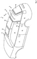
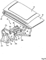
- the vehicle 1 shown in the drawing comprises at least above side windows 2 in each case rigid and body-mounted roof frame parts 3, which are in view from above substantially longitudinal to the vehicle extension between a windshield frame 4 and the rear portion 5 of the vehicle.
- the vehicle 1 further includes, which is not mandatory, a body 6 with four side doors 7, 8, wherein the roof frame parts 3 from the windshield frame 4 to the rear doors 8 immediately downstream and almost vertically towering body columns 9, the so-called. Columns, extend.
- a Vollcabriolet Scheme 10 with a movable rear roof section 11 which is also not mandatory, but improves the outdoor feeling.
- Other embodiments of the roof section 11 are possible.
- the vehicle 1 further includes in the illustrated embodiment in the direction of travel F adjacent to the rear roof section 11 and this further upstream movable roof parts 14, 15.
- Their number is variable depending on the roof length; they are in the closed state substantially horizontally, in alignment one behind the other and are based directly or indirectly on the lateral roof rails 3 from.
- the - here two - substantially plate-shaped roof parts 14, 15 may be formed of different materials, such as metallic, glass or plastic materials. In particular, they may be formed substantially transparent, wherein the front roof part 14 can connect directly to the windshield frame 4, to ensure a good outdoor feeling in the open position.
- the front roof part 14 is displaceable out of the closed position in the manner of a sunroof over the roof element 15 lying behind it and is in its open position substantially parallel to this ( Fig. 3 ).
- the position of the roof parts 14, 15 thus formed represents a possible permanent driving position.
- a further roof opening with downward displacement of the roof sections 14, 15 lying above one another as a package can be made out of it in order to lower it into the body 6, the body-mounted side frames 3 stand still and thus the rollover safety for the occupants remains.
- the roof parts 14, 15 are in the illustrated embodiment in the open, stored state at least almost horizontally below the lower edge of the side windows 7, 8 forming window parapet line 16 (FIG. Fig. 8 . Fig. 9 ).
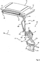
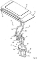
- For storage of the roof parts 14, 15 regardless of the rear roof section 11 is a further described below in detail linkage 25th
- a body-mounted guide rail 17 is provided on the lateral frame parts, in which the roof part 14 associated with its front end and provided with sliding or rolling elements 18 boom 19 can intervene ,
- the guide rails 17 extend against the direction of travel F slightly upwards, so that a guided therein roof part 14 is raised while moving backwards at the same time.
- the guide rails 17 open in the rear area in continuations 20, which are assigned to the underlying roof part 15 and therefore are movable with this.
- the sequels 20 are formed in the manner of pockets with pointing in the direction of travel F and are closed rear roof part 15 in alignment with the arranged in the roof frame parts body-mounted guide rails 17.
- the pockets 20 have only a small extension, just big enough to the slide - Or to be able to record 18 rolling body.
- the length of extension 20 is less than six centimeters.
- the rear end of the front roof part is connected via laterally located in the outer region pivot lever 21 with a slider 22 which is displaceable in a further longitudinal guide 23 which is associated with the rear roof part 15 and also movable therewith.
- a slider 22 which is displaceable in a further longitudinal guide 23 which is associated with the rear roof part 15 and also movable therewith.
- the continuation 20 has only small dimensions, the further longitudinal guide 23 can extend almost over the entire length of the rear roof part 15, without this having to have a large thickness.
- the pivot lever 21 engage in each case around the lateral edges of the roof part 15 in the longitudinal to the vehicle 1 extended longitudinal guides 23 a. to obtain.
- the gaps between roof part 15 and side frame 3 may be sealed with brush seals or rubber lips.
- FIGS. 15 to 20 From this position can, as in the FIGS. 15 to 20 is shown in a drawn out assembly drawing, the package from the roof parts 14 and 15 are stored in the body 6 in the window sill line 16, leaving a trunk ( Fig. 8 . Fig. 9 ).
- the linkage 25 has an upper and a lower four-bar linkage 26, 27, which can each be more or less opened or closed by a pivotably mounted drive member 28, 29.
- the four joints 26, 27 are connected via a pivot point 32 and a further lever 31 with each other.
- the lower four-bar linkage 27 remains stationary, while the upper four-bar joint 26 pivots through retraction of the drive member 28 to the rear.
- the handlebars 26a, 26b are rearwardly and downwardly displaced about the joints 26c, 26d held in this movement phase, and the associated roof parts 14, 15 are pivoted into an almost vertical position.
- the upper four-bar link 26 is not moved in it.
- the levers 26a, 26b do not change their relative position to each other and around the joints 26c, 26d.
- the rear roof section 11 does not need to be moved.
- the front roof part 14 only travels over the roof part 15 lying behind it. Also, during the storage of the roof parts 14, 15, the rear roof section 11 does not need to be completely opened, but only in its front area.
- the invention is applicable both to vehicles with manually moving roof parts 14, 15, 11 as well as fully or partially automatic mobility of the parts.
Landscapes
- Engineering & Computer Science (AREA)
- Mechanical Engineering (AREA)
- Body Structure For Vehicles (AREA)
Description
Die Erfindung betrifft ein Kraftfahrzeug mit karosseriefesten Dachrahmenteilen oberhalb von Seitenscheiben.The invention relates to a motor vehicle with body-mounted roof frame parts above side windows.
Ein solches Kraftfahrzeug ist aus der
Aus der
Der Erfindung liegt das Problem zugrunde, bei einem Cabriolet-Fahrzeug mit mehreren starren Dachteilen die Flexibilität der Dachöffnung zu optimieren.The invention is based on the problem of optimizing the flexibility of the roof opening in a convertible vehicle with a plurality of rigid roof parts.
Die Erfindung löst dieses Problem durch ein Kraftfahrzeug mit den Merkmalen des Anspruchs 1. Hinsichtlich weiterer vorteilhafter Ausgestaltungen der Erfindung wird auf die abhängigen Ansprüche verwiesen.The invention solves this problem by a motor vehicle having the features of claim 1. With regard to further advantageous embodiments of the invention, reference is made to the dependent claims.
Dadurch, daß zwischen den karosseriefesten Rahmenteilen eine Schiebedachfunktion von zumindest zwei in sich starren Dachteilen vorgesehen ist, kann mit der Erfindung das Freiluftgefühl auch bei ansonsten geschlossenem Dach verbessert sein. Dennoch ist ein gesamtes Ausheben der beiden Dachteile aus ihrer zwischen den seitlichen Dachrahmenteilen liegenden Stellung dadurch ermöglicht, daß die starre karosseriefeste Führungsschiene in eine mitbewegte Fortsetzung des hinteren Dachteils übergeht, so daß das vordere Dachteil in seiner nach Art eines Schiebedachs geöffneten Stellung vollständig an dem hinteren Dachteil zugeordnete Führungshilfen übergeben und somit von den karosseriefesten Führungsschienen unabhängig bewegbar ist. Durch die fluchtende Lage der beweglichen Fortsetzung ist die Übergabe nahezu ohne Überwindung einer Stufe und damit ohne einen deutlichen Widerstand möglich.The fact that between the body-mounted frame parts a sunroof function is provided by at least two inherently rigid roof parts, the open-air feeling can be improved even with otherwise closed roof with the invention. Nevertheless, an entire lifting of the two roof parts from its lying between the lateral roof frame parts position is made possible by the rigid body-mounted guide rail merges into a moving continuation of the rear roof part, so that the front roof part in its open in the manner of a sunroof open position completely on the rear Passing roof part assigned guide aids and thus is independent of the body-mounted guide rails movable. Due to the aligned position of the movable continuation, the transfer is almost without overcoming a stage and thus possible without a significant resistance.
Indem dem hinteren Dachteil neben der Fortsetzung der ansonsten karosseriefesten Führungsschiene eine weitere Längsführung zugeordnet ist, kann das vordere Dachteil an dem hinteren doppelt geführt sein, etwa mit einem hinteren Ausleger in der weiter oben liegenden Führungsbahn und mit einem vorderen Ausleger erst kurz vor der vollständig nach Art eines Schiebedachs geöffneten Stellung in die Fortsetzung eintreten. Diese kann vorteilhaft sehr kurz sein, insbesondere weniger als sechs Zentimeter lang, woraus resultiert, das auch das hintere Dachteil eine nur geringe Dicke aufzuweisen braucht und nur in einem begrenzten vorderen Bereich für die Fortsetzung eine Dickenzunahme benötigt. Das Packmaß der vollständig geöffneten Dachteile bleibt daher gering.By the rear roof part next to the continuation of the otherwise body-mounted guide rail is associated with a further longitudinal guide, the front roof part can be performed on the rear double, such as with a rear boom in the overhead track and with a front arm until just before the completely after Type of sunroof open position to enter the continuation. This can advantageously be very short, in particular less than six centimeters long, with the result that the rear roof part also needs to have only a small thickness and only requires a thickness increase in a limited front area for the continuation. The pack size of the fully opened roof parts therefore remains low.
Mit einem vorteilhaften Aufwärtsverlaufen der karosseriefesten Führungsschienen entgegen der Fahrtrichtung kann das vordere Dachteil ohne ein manuelles Anheben über das hintere verlagerbar sein und daher auch bei seiner Öffnung die volle Kopffreiheit bewahren. Durch die einfache Translationsbewegung für die Schiebedachöffnung in den gekrümmten Führungsschienen ist diese auch manuell möglich.With an advantageous upward running of the body-mounted guide rails against the direction of travel, the front roof part can be displaced over the rear without manual lifting and therefore maintain full headroom even when it is opened. Due to the simple translational movement for the sunroof opening in the curved guide rails, this is also possible manually.
Weitere Vorteile und Merkmale der Erfindung ergeben sich aus in der Zeichnung dargestellten und nachfolgend beschriebenen Ausführungsbeispielen des Gegenstandes der Erfindung.Further advantages and features of the invention will become apparent from the drawing illustrated and described below embodiments of the subject invention.
In der Zeichnung zeigt:
- Fig. 1
- eine perspektivische Gesamtansicht eines erfindungsgemäßen Kraftfahrzeugs mit geschlossenen Dachteilen und geschlossenem hinterem Dachabschnitt,
- Fig. 2
- eine ähnliche Ansicht wie
Fig. 1 bei beginnender Verlagerung eines vorderen plattenförmigen Dachteils über das dahinter liegende nach Art eines Schiebedachs, - Fig. 3
- eine ähnliche Ansicht wie
Fig. 2 mit vollständig geöffnetem Schiebedach und geschlossenem hinterem Dachabschnitt, - Fig. 4
- eine ähnliche Ansicht wie
Fig. 3 bei beginnender Öffnung des hinteren Dachabschnitts, - Fig. 5
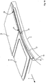
- eine Seitenansicht des Fahrzeugs nach
Fig. 4 während des Absenkens der vorderen Dachteile bei teilweise geöffnetem hinterem Dachabschnitt, - Fig. 6
- eine Ausschnittsvergrößerung des Fahrzeugheckbereichs in Seitenansicht während der Ablagephase der Dachteile,
- Fig. 7
- eine ähnliche Ansicht wie
Fig. 6 bei in Öffnungsstellung vollständig horizontal abgelegten Dachteilen, - Fig. 8
- eine ähnliche Ansicht wie
Fig. 7 nach Schließen des hinteren Dachabschnitts über den abgelegten Dachteilen, - Fig. 9
- eine ähnliche Ansicht wie
Fig. 7 nach Öffnen des hinteren Dachabschnitts und seiner Ablage über den geöffneten Dachteilen, - Fig. 10
- einen Detailausschnitt der als Einzelteile herausgezeichneten, fluchtend hintereinander liegenden Dachteile in der nach
Fig. 1 geschlossenen Stellung, - Fig. 11
- eine ähnliche Ansicht wie
Fig. 10 der Dachteile in einer Öffnungsstellung etwa entsprechend der ausFig. 2 , - Fig. 12
- eine ähnliche Ansicht wie
Fig. 11 der Dachteile in einer Öffnungsstellung etwa entsprechend der ausFig. 3 , - Fig. 13
- die Teile in Stellung nach
Fig. 12 in Seitenansicht, - Fig. 14
- ein ähnliche Ansicht wie
Fig. 13 während der beginnenden Ablage der Dachteile in der Karosserie, - Fig. 15 bis Fig. 20
- den Ablagemechanismus der übereinander liegenden Dachteile zu ihrer Ablage in der Karosserie, darin
- Fig. 15
- die noch horizontal an den seitlichen Rahmenteilen abgestützten Dachteile,
- Fig. 16 bis Fig. 19
- chronologisch aufeinander folgende Stadien der Dachteilöffnung,
- Fig. 20
- die Dachteile in vollständig geöffneter horizontaler Ablagestellung.
- Fig. 1
- an overall perspective view of a motor vehicle according to the invention with closed roof parts and closed rear roof section,
- Fig. 2
- a similar view as
Fig. 1 at the beginning of relocation of a front plate-shaped roof part on the underlying behind the manner of a sunroof, - Fig. 3
- a similar view as
Fig. 2 with fully open sunroof and closed rear roof section, - Fig. 4
- a similar view as
Fig. 3 at the beginning of the opening of the rear roof section, - Fig. 5
- a side view of the vehicle after
Fig. 4 during the lowering of the front roof parts with partially opened rear roof section, - Fig. 6
- an enlarged detail of the vehicle rear area in side view during the storage phase of the roof parts,
- Fig. 7
- a similar view as
Fig. 6 in the open position completely horizontally stored roof parts, - Fig. 8
- a similar view as
Fig. 7 after closing the rear roof section over the stored Roof parts, - Fig. 9
- a similar view as
Fig. 7 after opening the rear roof section and its shelf over the opened roof parts, - Fig. 10
- a detail of the drawn out as items, aligned one behind the other roof parts in the after
Fig. 1 closed position, - Fig. 11
- a similar view as
Fig. 10 the roof parts in an open position approximately according to theFig. 2 . - Fig. 12
- a similar view as
Fig. 11 the roof parts in an open position approximately according to theFig. 3 . - Fig. 13
- the parts in position after
Fig. 12 in side view, - Fig. 14
- a similar view as
Fig. 13 during the incipient storage of the roof parts in the body, - FIGS. 15 to 20
- the storage mechanism of the superposed roof parts to their storage in the body, in it
- Fig. 15
- the still horizontally supported on the lateral frame parts roof parts,
- FIG. 16 to FIG. 19
- chronologically consecutive stages of the roof part opening,
- Fig. 20
- the roof parts in fully opened horizontal storage position.
Das in der Zeichnung dargestellte Fahrzeug 1 umfaßt zumindest oberhalb seitlicher Scheiben 2 in sich jeweils starre und karosseriefeste Dachrahmenteile 3, die in Ansicht von oben im wesentlichen längs zur Fahrzeugerstreckung zwischen einem Windschutzscheibenrahmen 4 und dem Heckbereich 5 des Fahrzeugs liegen.The vehicle 1 shown in the drawing comprises at least above
Das Fahrzeug 1 umfaßt weiter, was nicht zwingend ist, eine Karosserie 6 mit vier seitlichen Türen 7, 8, wobei sich die Dachrahmenteile 3 vom Windschutzscheibenrahmen 4 bis zu den hinteren Türen 8 unmittelbar nachgeordneten und nahezu vertikal aufragenden Karosseriesäulen 9, den sog. C-Säulen, erstrecken.The vehicle 1 further includes, which is not mandatory, a
Im hinteren Fahrzeugbereich 5, beginnend hinter den Karosseriesäulen 9, schließt sich im Ausführungsbeispiel ein Vollcabrioletbereich 10 mit einem beweglichen hinteren Dachabschnitt 11 an, was ebenfalls nicht zwingend ist, jedoch das Freiluftgefühl verbessert. Dieser umfaßt eine Heckscheibe 12, die von einem den Dachabschnitt 11 außerhalb der Heckscheibe 12 vollständig überspannenden Bezug 13 umgeben ist. Auch andere Ausbildungen des Dachabschnitts 11 sind möglich.In the rear of the
Das Fahrzeug 1 umfaßt weiter im gezeichneten Ausführungsbeispiel in Fahrtrichtung F an den hinteren Dachabschnitt 11 angrenzend und diesem vorgeordnet weitere bewegliche Dachteile 14, 15. Ihre Anzahl ist je nach Dachlänge variabel; sie liegen im geschlossenen Zustand im wesentlichen horizontal, fluchtend hintereinander und stützen sich unmittelbar oder mittelbar an den seitlichen Dachholmen 3 ab. Die - hier zwei - im wesentlichen plattenförmigen Dachteile 14, 15 können aus unterschiedlichen Materialien, etwa metallischen, Glas- oder Kunststoffwerkstoffen, gebildet sein. Insbesondere können sie im wesentlichen transparent ausgebildet sein, wobei das vordere Dachteil 14 unmittelbar an den Windschutzscheibenrahmen 4 anschließen kann, um in Offenstellung ein gutes Freiluftgefühl zu gewährleisten.The vehicle 1 further includes in the illustrated embodiment in the direction of travel F adjacent to the
Das vordere Dachteil 14 ist aus der geschlossenen Stellung heraus nach Art eines Schiebedachs über das dahinter liegende Dachteil 15 verlagerbar und liegt in seiner geöffneten Stellung im wesentlichen parallel auf diesem (
Um die Bewegung des vorderen Dachteils 14 gegenüber dem dahinter liegenden Dachteil 15 zu ermöglichen, ist an den seitlichen Rahmenteilen jeweils eine karosseriefeste Führungsschiene 17 vorgesehen, in die das Dachteil 14 über seinem vorderen Ende zugeordnete und mit Gleit- oder Rollkörpern 18 versehene Ausleger 19 eingreifen kann. Die Führungsschienen 17 verlaufen entgegen der Fahrtrichtung F leicht aufwärts, so daß ein darin geführtes Dachteil 14 bei seiner Bewegung nach hinten gleichzeitig angehoben wird. Die Führungsschienen 17 münden im hinteren Bereich in Fortsetzungen 20, die dem dahinter liegenden Dachteil 15 zugeordnet und daher mit diesem beweglich sind.In order to enable the movement of the
Die Fortsetzungen 20 sind nach Art von Taschen mit in Fahrtrichtung F weisender Öffnung gebildet und liegen bei geschlossenem hinterem Dachteil 15 fluchtend zu den in den Dachrahmenteilen angeordneten karosseriefesten Führungsschienen 17. Die Taschen 20 haben dabei nur eine geringe Erstreckung, gerade groß genug, um den Gleit- oder Rollkörper 18 aufnehmen zu könnten. Typischerweise beträgt die Längserstreckung der Fortsetzung 20 weniger als sechs Zentimeter.The
Das hintere Ende des vorderen Dachteils ist über seitlich im äußeren Bereich liegende Schwenkhebel 21 mit einem Gleiter 22 verbunden, der in einer weiteren Längsführung 23, die dem hinteren Dachteil 15 zugeordnet und ebenfalls mit diesem beweglich ist, verschieblich ist. Dadurch, daß die Fortsetzung 20 nur geringe Ausmaße aufweist, kann die weitere Längsführung 23 sich nahezu über die gesamte Länge des hinteren Dachteils 15 erstrecken, ohne daß dieses eine große Dicke aufweisen muß.The rear end of the front roof part is connected via laterally located in the outer
Die Schwenkhebel 21 greifen dabei jeweils um die seitlichen Kanten des Dachteils 15 herum in die längs zum Fahrzeug 1 erstreckten Längsführungen 23 ein. zu erhalten. Die Spalte zwischen Dachteil 15 und Seitenrahmen 3 können etwa mit Bürstendichtungen oder Gummilippen abgedichtet sein.The
Im geschlossenen Zustand und bei der Schiebedachöffnung des vorderen Dachteils 14 ist dieses mit seinen vorderen Auslegern 19 in den karosseriefesten Führungsschienen 17 gehalten; die hinteren Schwenkhebel 21 sind hingegen während jedes Bewegungszustands des vorderen Dachteils 14 an den Längsführungen 23 geführt. Im Übergang aus dem geschlossenen Zustand nach
Aus dieser Stellung heraus kann, wie in den
Für die vollständige Öffnung der Dachteile 14, 15 sind diese an einem gemeinsamen Gestänge 25 unabhängig vom hinteren Dachabschnitt 11 gehalten. Mit Hilfe dieses Gestänges 25 sind sie aus der übereinander liegenden Paketstellung (
Das Gestänge 25 weist hierzu ein oberes und ein unteres Viergelenk 26, 27 auf, die jeweils durch ein schwenkbar gelagertes Antriebsorgan 28, 29 mehr oder weniger geöffnet oder geschlossen werden können. Die Viergelenke 26, 27 sind über einen Drehpunkt 32 und einen weiteren Hebel 31 miteinander verbunden.For this purpose, the
In der ersten Phase der Öffnung (
In der zweiten Phase der Öffnung (
Das obere Viergelenk 26 wird dabei in sich nicht mehr bewegt. Die Hebel 26a, 26b verändern ihre relative Lage zueinander und um die Gelenke 26c, 26d nicht.The upper four-
Gleichzeitig wird jedoch durch den zwischen den Viergelenken 26 und 27 liegenden weiteren Hebel 31 und den Drehpunkt 32 die Bewegung des unteren Viergelenks 27 auf einen Träger 33 und somit auf die Gelenke 26c und 26d übertragen, die an dem gemeinsamen Träger 33 gehalten sind, daß sie aus ihrer nahezu übereinander liegenden Lage nach
Am Ende der umgekehrten Bewegung zum Schließen der Dachteile 14, 15 ist das hintere, von dem Gestänge 25 bewegte Dachteil 15 an den seitlichen Rahmenteilen 3 zentrierbar und verriegelbar, etwa über konische und damit selbst zentrierende zapfen, die in entsprechende Ausnehmungen der Rahmenteile 3 eingreifen.At the end of the reverse movement to close the
Da die Bewegung der Dachteile 14, 15 über das Gestänge 25 unabhängig von der Bewegung des hinteren Dachabschnitts 11 ist, erlaubt das Fahrzeug 1 eine Vielzahl von dauerhaften Öffnungszuständen des Daches:
- zunächst eine vollständig geschlossene
Stellung von Dachteilen Fig. 1 ) ; des weiteren eine nach Art eines Schiebedachs geöffnete oder eine vollständig geöffnete und in derKarosserie 6 abgelegte Stellung der Dachteile 14, 15 bei geschlossenem hinterem Dachabschnitt 11 (Fig. 8 ); die vollständig geöffnete Stellung der Dachteile 14, 15 mit darüber geöffnetem hinterem Dachabschnitt 11, so daß der hinterden Karosseriesäulen 9liegende Karosseriebereich 5 wie bei einem Vollcabriolet geöffnet ist (Fig. 9 ). Schließlich kann auch nur der hintere Dachabschnitt 11 nach Art eines Landaulet-Fahrzeugs geöffnet werden, während dieDachteile
- first a completely closed position of
roof parts Fig. 1 ); Furthermore, an opened in the manner of a sunroof or a fully open and stored in thebody 6 position of theroof parts Fig. 8 ); the fully open position of theroof parts rear roof section 11 opened above, so that thebody region 5 located behind thebody pillars 9 is opened as in a full convertible (Fig. 9 ). Finally, only therear roof section 11 can be opened in the manner of a Landaulet vehicle, while theroof parts
Für die Schiebedachöffnung (Übergang von
Die Erfindung ist sowohl bei Fahrzeugen mit manuell zu bewegenden Dachteilen 14, 15, 11 als auch bei voll- oder teilautomatischer Beweglichkeit der Teile anwendbar.The invention is applicable both to vehicles with manually moving
Claims (7)
- A motor vehicle (1) with a vehicle body (6), which comprises roof frame parts (3) fixed to the vehicle body and extending above side windows (2) and at least two movable and substantially plate-shaped roof parts (14;15) which are arranged in sequence and aligned with each other in the closed position,
wherein the front roof part (14) of said two roof parts can be moved in the manner of a sunroof under or, in particular, over the roof part (15) located behind it, for which purpose each of the lateral frame parts (3) has a respective body-fixed guide rail (17) for the front one of the two roof parts (14;15) assigned to it, said guide rail (17) terminating, in the area of its rear end located counter to the direction of travel, in an extension (20) which is assigned to the rear roof part (15) and can be moved together with the latter,
wherein, in addition to the extension (20) of the guide rail (17) otherwise fixed to the vehicle body, another, longitudinal guide (23) is assigned to the rear roof part (15), and hereby, when opened completely in the manner of a sunroof, the front roof part (14) is double guided along the rear roof part (15),
wherein, when opened in the manner of a sunroof, the front roof part (14) is held by its front area in the movable extensions (20) of the guide rails (17), and is held by its rear area in the longitudinal guides (23) assigned to the rear roof part (15),
wherein, in order to adjust an overall opening position, the roof parts (14; 15) can be detached completely from the lateral roof frame parts (3) and can be moved into the vehicle body (6) by means of at least one linkage (25),
and wherein the area of fixed lateral roof frame parts (3) terminates at an upwardly extending body pillar (9) in the rear area of a side door (8), thereto adjoining at the rear a full-convertible area (10) which can be retracted as a whole. - The motor vehicle (1) according to claim 1, characterised in that, in closed state and as it begins to open, the front roof part (14) is held in the manner of a sunroof, with its front area being held in the body-fixed guide rails (17) and its rear area being held in the movable longitudinal guides (23).
- The motor vehicle according to any one of claims 1 or 2, characterised in that the front roof part (14) can be moved over the rear roof part (15), and the guide rails (17) fixed to the vehicle body extend upwards counter to the direction of travel (F).
- The motor vehicle according to any one of claims 1 to 3, characterised in that the front roof part (14) enters into engagement with the guide rails (17) and the extensions (20), respectively, via sliding or rolling bodies (18) fixed to arms (19).
- The motor vehicle according to any one of claims 1 to 4, characterised in that the movable extensions (20) of the guide rails (17) fixed to the vehicle body are provided in the manner of pockets and extend over less than six centimetres in the longitudinal vehicle direction.
- The motor vehicle according to claim 1, characterised in that, during the movement of the roof parts (14;15) into their overall opening position, the front roof part (14), opened in the manner of a sunroof, is parallel to the rear roof part (15).
- The motor vehicle according to any one of claims 1 to 6, characterised in that the rear roof part (15) can be centred and locked on the lateral frame parts (3).
Applications Claiming Priority (2)
| Application Number | Priority Date | Filing Date | Title |
|---|---|---|---|
| DE200410020008 DE102004020008A1 (en) | 2004-04-21 | 2004-04-21 | motor vehicle |
| PCT/DE2005/000720 WO2005102755A1 (en) | 2004-04-21 | 2005-04-20 | Motor vehicle comprising displaceable plate-shaped roof parts |
Publications (3)
| Publication Number | Publication Date |
|---|---|
| EP1744919A1 EP1744919A1 (en) | 2007-01-24 |
| EP1744919B1 EP1744919B1 (en) | 2013-07-24 |
| EP1744919B2 true EP1744919B2 (en) | 2017-01-25 |
Family
ID=34965645
Family Applications (1)
| Application Number | Title | Priority Date | Filing Date |
|---|---|---|---|
| EP05736326.9A Not-in-force EP1744919B2 (en) | 2004-04-21 | 2005-04-20 | Motor vehicle comprising displaceable plate-shaped roof parts |
Country Status (3)
| Country | Link |
|---|---|
| EP (1) | EP1744919B2 (en) |
| DE (1) | DE102004020008A1 (en) |
| WO (1) | WO2005102755A1 (en) |
Families Citing this family (5)
| Publication number | Priority date | Publication date | Assignee | Title |
|---|---|---|---|---|
| DE102005006435B4 (en) | 2005-02-12 | 2017-11-23 | Valmet Automotive Oy | Motor vehicle with an at least partially movable roof |
| DE102005049933A1 (en) | 2005-10-19 | 2007-04-26 | GM Global Technology Operations, Inc., Detroit | Convertible motor vehicle |
| DE102006023346A1 (en) * | 2006-05-17 | 2007-11-22 | Wilhelm Karmann Gmbh | Cabriolet vehicle has connection in rear between vehicle body and at least one roof part with flexible roof section with outer cover region |
| FR2903939B1 (en) * | 2006-07-19 | 2008-08-15 | Heuliez Sa | RETRACTABLE ROOF WITH SLIDING PANELS WITH SOLAR PROTECTION |
| DE102008048565B4 (en) | 2008-09-23 | 2012-11-08 | Gve Viehbeck Engineering + Systemtechnik Gmbh | Shading device for a headgear windshield |
Citations (7)
| Publication number | Priority date | Publication date | Assignee | Title |
|---|---|---|---|---|
| DE29804387U1 (en) † | 1998-03-12 | 1999-07-15 | Strobel, Martin, Dipl.-Designer, 64823 Groß-Umstadt | sunroof |
| DE19908253A1 (en) † | 1999-02-25 | 2000-09-07 | Audi Ag | Body structure with movable cover elements |
| DE19943713C1 (en) † | 1999-09-13 | 2000-10-12 | Webasto Dachsysteme Gmbh | Automobile sliding sunroof has a locking system operated independently of the coupling to give a free movement to the sliding carrier when uncoupled from the slide |
| DE10025051C1 (en) † | 2000-05-23 | 2001-11-15 | Webasto Vehicle Sys Int Gmbh | Car has sunshine roof which extends across its whole width and slides back on to rear window both components then sliding back over boot |
| DE10043712A1 (en) † | 2000-09-04 | 2002-04-04 | Webasto Vehicle Sys Int Gmbh | Convertible vehicle roof has roof part able to slide along lateral roof bars; roof part(s) is/are movable onto roof unit or rear unit before roof is lowered into stowage compartment |
| US6419308B1 (en) † | 1999-10-29 | 2002-07-16 | Asc Incorporated | Movable roof system for an automotive vehicle |
| DE20204110U1 (en) † | 2002-03-14 | 2002-09-12 | Inalfa Industries B.V., Venray | Vehicle with a roof arrangement; and such a roof arrangement |
Family Cites Families (10)
| Publication number | Priority date | Publication date | Assignee | Title |
|---|---|---|---|---|
| DE29622436U1 (en) * | 1996-12-28 | 1998-01-08 | Wilhelm Karmann GmbH, 49084 Osnabrück | Motor vehicle |
| DE19851231A1 (en) * | 1998-11-06 | 2000-05-11 | Bayerische Motoren Werke Ag | Passenger cars |
| DE19927234C1 (en) * | 1999-06-15 | 2000-07-27 | Webasto Vehicle Sys Int Gmbh | Guide rail for accommodating displaceable vehicle roof part(s) has first section with centring element that interacts with complementary counter element on second section |
| FR2797226B1 (en) * | 1999-08-05 | 2001-09-21 | France Design | RETRACTABLE ROOF SYSTEM |
| DE10023864B4 (en) * | 2000-05-16 | 2005-06-23 | Webasto Ag | Folding hood of a vehicle |
| NL1016394C2 (en) * | 2000-10-12 | 2002-04-16 | Inalfa Ind Bv | Folding roof for motor vehicle has panels movable backwards along guide device from completely closed position to one entirely open in which panels form vertically extending packet |
| EP1829723B1 (en) * | 2000-11-09 | 2009-02-25 | Inalfa Roof Systems Group B.V. | Open roof construction for a vehicle, as well as vehicle having such open roof construction |
| DE20313456U1 (en) * | 2002-10-17 | 2003-11-13 | Wilhelm Karmann GmbH, 49084 Osnabrück | Convertible car |
| FR2851747B1 (en) * | 2003-02-28 | 2006-06-02 | France Design | RETRACTABLE ROOF OF VEHICLE |
| DE20305952U1 (en) * | 2003-04-11 | 2003-09-04 | Schmidt, Felix, Basel | Opening roof for motor vehicle has rear panel mounted on side beams and front panel foldable to allow stowage |
-
2004
- 2004-04-21 DE DE200410020008 patent/DE102004020008A1/en not_active Withdrawn
-
2005
- 2005-04-20 EP EP05736326.9A patent/EP1744919B2/en not_active Not-in-force
- 2005-04-20 WO PCT/DE2005/000720 patent/WO2005102755A1/en active Application Filing
Patent Citations (7)
| Publication number | Priority date | Publication date | Assignee | Title |
|---|---|---|---|---|
| DE29804387U1 (en) † | 1998-03-12 | 1999-07-15 | Strobel, Martin, Dipl.-Designer, 64823 Groß-Umstadt | sunroof |
| DE19908253A1 (en) † | 1999-02-25 | 2000-09-07 | Audi Ag | Body structure with movable cover elements |
| DE19943713C1 (en) † | 1999-09-13 | 2000-10-12 | Webasto Dachsysteme Gmbh | Automobile sliding sunroof has a locking system operated independently of the coupling to give a free movement to the sliding carrier when uncoupled from the slide |
| US6419308B1 (en) † | 1999-10-29 | 2002-07-16 | Asc Incorporated | Movable roof system for an automotive vehicle |
| DE10025051C1 (en) † | 2000-05-23 | 2001-11-15 | Webasto Vehicle Sys Int Gmbh | Car has sunshine roof which extends across its whole width and slides back on to rear window both components then sliding back over boot |
| DE10043712A1 (en) † | 2000-09-04 | 2002-04-04 | Webasto Vehicle Sys Int Gmbh | Convertible vehicle roof has roof part able to slide along lateral roof bars; roof part(s) is/are movable onto roof unit or rear unit before roof is lowered into stowage compartment |
| DE20204110U1 (en) † | 2002-03-14 | 2002-09-12 | Inalfa Industries B.V., Venray | Vehicle with a roof arrangement; and such a roof arrangement |
Also Published As
| Publication number | Publication date |
|---|---|
| WO2005102755A1 (en) | 2005-11-03 |
| EP1744919A1 (en) | 2007-01-24 |
| EP1744919B1 (en) | 2013-07-24 |
| DE102004020008A1 (en) | 2005-11-10 |
Similar Documents
| Publication | Publication Date | Title |
|---|---|---|
| DE102005030055B4 (en) | Sunroof for vehicles has side skirt arranged adjacent seal provided close to upper end of guide rail or at edge of opening | |
| EP1758749B1 (en) | Convertible vehicle | |
| WO1997037866A1 (en) | Kinematic folding top for passenger cars | |
| EP1670657B1 (en) | Motor vehicle comprising a fully opening roof part | |
| EP1554147B1 (en) | Movable multisection roof for a motor vehicle | |
| DE102006008290A1 (en) | Retractable column for a vehicle with a folding top | |
| EP1565335B1 (en) | Motor vehicle | |
| DE10152944A1 (en) | Convertible top for a convertible vehicle | |
| EP1900562B1 (en) | Convertible vehicle with a roof composed of several parts | |
| EP1744919B2 (en) | Motor vehicle comprising displaceable plate-shaped roof parts | |
| WO2013170993A1 (en) | Vehicle roof with two cover elements | |
| EP1736338B1 (en) | Convertible with a rear roof element | |
| EP1670654B1 (en) | Motor vehicle hatchback with a storable rear window | |
| DE102008046331A1 (en) | Vehicle roof, has center and rear sliding elements movably led to guide, and front sliding element connected with raising lever and staying in contact with another guide, which is arranged at movable roof part | |
| DE10140233B4 (en) | Cabriolet vehicle with a storable under a cover part roof | |
| EP1647431B1 (en) | Motor vehicle with a front roof panel | |
| EP1588881B1 (en) | Vehicle with movable roof parts | |
| EP1554144B1 (en) | Motor vehicle | |
| EP1798085B1 (en) | Vehicle roof system for a cabriolet | |
| EP1565336B1 (en) | Motor vehicle | |
| DE29901054U1 (en) | Cabriolet vehicle with a convertible top storage compartment | |
| EP1758751A1 (en) | Convertible vehicle | |
| EP1670655B1 (en) | Motor vehicle with a hatchback and opening roof part | |
| DE102005041023A1 (en) | Body structure for motor vehicle e.g. jeep, has guiding rails formed such that rear window is transferred from one state to other state by translatory and rotatory movement, where rear window lies horizontally and below rear opening center | |
| DE10327355B4 (en) | Convertible top assembly |
Legal Events
| Date | Code | Title | Description |
|---|---|---|---|
| PUAI | Public reference made under article 153(3) epc to a published international application that has entered the european phase |
Free format text: ORIGINAL CODE: 0009012 |
|
| 17P | Request for examination filed |
Effective date: 20061121 |
|
| AK | Designated contracting states |
Kind code of ref document: A1 Designated state(s): DE FR GB IT |
|
| DAX | Request for extension of the european patent (deleted) | ||
| RBV | Designated contracting states (corrected) |
Designated state(s): DE FR GB IT |
|
| 17Q | First examination report despatched |
Effective date: 20080421 |
|
| 19U | Interruption of proceedings before grant |
Effective date: 20090629 |
|
| 19W | Proceedings resumed before grant after interruption of proceedings |
Effective date: 20101201 |
|
| GRAP | Despatch of communication of intention to grant a patent |
Free format text: ORIGINAL CODE: EPIDOSNIGR1 |
|
| RAP1 | Party data changed (applicant data changed or rights of an application transferred) |
Owner name: VALMET AUTOMOTIVE OY |
|
| GRAS | Grant fee paid |
Free format text: ORIGINAL CODE: EPIDOSNIGR3 |
|
| GRAA | (expected) grant |
Free format text: ORIGINAL CODE: 0009210 |
|
| AK | Designated contracting states |
Kind code of ref document: B1 Designated state(s): DE FR GB IT |
|
| REG | Reference to a national code |
Ref country code: GB Ref legal event code: FG4D Free format text: NOT ENGLISH |
|
| REG | Reference to a national code |
Ref country code: DE Ref legal event code: R096 Ref document number: 502005013868 Country of ref document: DE Effective date: 20130919 |
|
| PLBI | Opposition filed |
Free format text: ORIGINAL CODE: 0009260 |
|
| 26 | Opposition filed |
Opponent name: WEBASTO-EDSCHA CABRIO GMBH Effective date: 20140424 |
|
| PG25 | Lapsed in a contracting state [announced via postgrant information from national office to epo] |
Ref country code: IT Free format text: LAPSE BECAUSE OF FAILURE TO SUBMIT A TRANSLATION OF THE DESCRIPTION OR TO PAY THE FEE WITHIN THE PRESCRIBED TIME-LIMIT Effective date: 20130724 |
|
| PLAX | Notice of opposition and request to file observation + time limit sent |
Free format text: ORIGINAL CODE: EPIDOSNOBS2 |
|
| REG | Reference to a national code |
Ref country code: DE Ref legal event code: R026 Ref document number: 502005013868 Country of ref document: DE Effective date: 20140424 |
|
| PLAF | Information modified related to communication of a notice of opposition and request to file observations + time limit |
Free format text: ORIGINAL CODE: EPIDOSCOBS2 |
|
| PLBB | Reply of patent proprietor to notice(s) of opposition received |
Free format text: ORIGINAL CODE: EPIDOSNOBS3 |
|
| REG | Reference to a national code |
Ref country code: FR Ref legal event code: PLFP Year of fee payment: 11 |
|
| REG | Reference to a national code |
Ref country code: FR Ref legal event code: PLFP Year of fee payment: 12 |
|
| RIC2 | Information provided on ipc code assigned after grant |
Ipc: B60J 7/047 20060101AFI20160606BHEP Ipc: B60J 7/20 20060101ALI20160606BHEP |
|
| PGFP | Annual fee paid to national office [announced via postgrant information from national office to epo] |
Ref country code: GB Payment date: 20160628 Year of fee payment: 12 |
|
| PGFP | Annual fee paid to national office [announced via postgrant information from national office to epo] |
Ref country code: FR Payment date: 20160621 Year of fee payment: 12 |
|
| PUAH | Patent maintained in amended form |
Free format text: ORIGINAL CODE: 0009272 |
|
| STAA | Information on the status of an ep patent application or granted ep patent |
Free format text: STATUS: PATENT MAINTAINED AS AMENDED |
|
| 27A | Patent maintained in amended form |
Effective date: 20170125 |
|
| AK | Designated contracting states |
Kind code of ref document: B2 Designated state(s): DE FR GB IT |
|
| REG | Reference to a national code |
Ref country code: DE Ref legal event code: R102 Ref document number: 502005013868 Country of ref document: DE |
|
| GBPC | Gb: european patent ceased through non-payment of renewal fee |
Effective date: 20170420 |
|
| REG | Reference to a national code |
Ref country code: FR Ref legal event code: ST Effective date: 20171229 |
|
| PG25 | Lapsed in a contracting state [announced via postgrant information from national office to epo] |
Ref country code: FR Free format text: LAPSE BECAUSE OF NON-PAYMENT OF DUE FEES Effective date: 20170502 |
|
| PG25 | Lapsed in a contracting state [announced via postgrant information from national office to epo] |
Ref country code: GB Free format text: LAPSE BECAUSE OF NON-PAYMENT OF DUE FEES Effective date: 20170420 |
|
| PGFP | Annual fee paid to national office [announced via postgrant information from national office to epo] |
Ref country code: DE Payment date: 20180625 Year of fee payment: 14 |
|
| REG | Reference to a national code |
Ref country code: DE Ref legal event code: R119 Ref document number: 502005013868 Country of ref document: DE |
|
| PG25 | Lapsed in a contracting state [announced via postgrant information from national office to epo] |
Ref country code: DE Free format text: LAPSE BECAUSE OF NON-PAYMENT OF DUE FEES Effective date: 20191101 |