EP1744582A1 - Method and aparatus for performing handover between core network entities in a packet-swiched network - Google Patents
Method and aparatus for performing handover between core network entities in a packet-swiched network Download PDFInfo
- Publication number
- EP1744582A1 EP1744582A1 EP06014758A EP06014758A EP1744582A1 EP 1744582 A1 EP1744582 A1 EP 1744582A1 EP 06014758 A EP06014758 A EP 06014758A EP 06014758 A EP06014758 A EP 06014758A EP 1744582 A1 EP1744582 A1 EP 1744582A1
- Authority
- EP
- European Patent Office
- Prior art keywords
- new
- ran
- handover
- old
- address
- Prior art date
- Legal status (The legal status is an assumption and is not a legal conclusion. Google has not performed a legal analysis and makes no representation as to the accuracy of the status listed.)
- Granted
Links
- 238000000034 method Methods 0.000 title claims abstract description 25
- 230000004044 response Effects 0.000 claims abstract description 21
- 238000005259 measurement Methods 0.000 claims description 22
- 230000011664 signaling Effects 0.000 description 9
- 238000004891 communication Methods 0.000 description 5
- 230000005540 biological transmission Effects 0.000 description 4
- 238000010295 mobile communication Methods 0.000 description 4
- 238000010276 construction Methods 0.000 description 2
- 238000012217 deletion Methods 0.000 description 2
- 230000037430 deletion Effects 0.000 description 2
- 238000010586 diagram Methods 0.000 description 2
- 230000005641 tunneling Effects 0.000 description 2
- 238000005516 engineering process Methods 0.000 description 1
- 230000007774 longterm Effects 0.000 description 1
- 230000007246 mechanism Effects 0.000 description 1
- 238000012986 modification Methods 0.000 description 1
- 230000004048 modification Effects 0.000 description 1
- 238000012546 transfer Methods 0.000 description 1
Images


Classifications
-
- H—ELECTRICITY
- H04—ELECTRIC COMMUNICATION TECHNIQUE
- H04L—TRANSMISSION OF DIGITAL INFORMATION, e.g. TELEGRAPHIC COMMUNICATION
- H04L12/00—Data switching networks
- H04L12/54—Store-and-forward switching systems
- H04L12/56—Packet switching systems
-
- H—ELECTRICITY
- H04—ELECTRIC COMMUNICATION TECHNIQUE
- H04W—WIRELESS COMMUNICATION NETWORKS
- H04W36/00—Hand-off or reselection arrangements
- H04W36/0005—Control or signalling for completing the hand-off
- H04W36/0011—Control or signalling for completing the hand-off for data sessions of end-to-end connection
- H04W36/0033—Control or signalling for completing the hand-off for data sessions of end-to-end connection with transfer of context information
-
- H—ELECTRICITY
- H04—ELECTRIC COMMUNICATION TECHNIQUE
- H04W—WIRELESS COMMUNICATION NETWORKS
- H04W36/00—Hand-off or reselection arrangements
- H04W36/14—Reselecting a network or an air interface
-
- H—ELECTRICITY
- H04—ELECTRIC COMMUNICATION TECHNIQUE
- H04W—WIRELESS COMMUNICATION NETWORKS
- H04W36/00—Hand-off or reselection arrangements
- H04W36/14—Reselecting a network or an air interface
- H04W36/144—Reselecting a network or an air interface over a different radio air interface technology
- H04W36/1446—Reselecting a network or an air interface over a different radio air interface technology wherein at least one of the networks is unlicensed
-
- H—ELECTRICITY
- H04—ELECTRIC COMMUNICATION TECHNIQUE
- H04W—WIRELESS COMMUNICATION NETWORKS
- H04W80/00—Wireless network protocols or protocol adaptations to wireless operation
- H04W80/04—Network layer protocols, e.g. mobile IP [Internet Protocol]
-
- H—ELECTRICITY
- H04—ELECTRIC COMMUNICATION TECHNIQUE
- H04W—WIRELESS COMMUNICATION NETWORKS
- H04W88/00—Devices specially adapted for wireless communication networks, e.g. terminals, base stations or access point devices
- H04W88/16—Gateway arrangements
Definitions
- the present invention relates generally to a packet-switched network. More particularly, the present invention relates to a method and apparatus for simultaneously performing Layer 2 (L2) handover between Radio Access Networks (RANs) and Layer 3 (L3) handover between Core Networks (CNs) for handover between CN entities.
- L2 Layer 2
- RANs Radio Access Networks
- L3 Layer 3
- CNs Core Networks
- Universal Mobile Telecommunication System (UMTS), an asynchronous 3rd Generation (3G) mobile communication system based on European Global System for Mobile communications (GSM) and General Packet Radio Services (GPRS) and operating in Wideband Code Division Multiple Access (WCDMA), provides a uniform service of sending packet text, digital voice or video, and multimedia data at or above 2Mbps to mobile users or computer users irrespective of their locations.
- GSM Global System for Mobile communications
- GPRS General Packet Radio Services
- WCDMA Wideband Code Division Multiple Access
- UMTS enables access to any end point within a network.
- the virtual access refers to packet-switched connection using a packet protocol like Internet Protocol (IP).
- IP Internet Protocol
- E-UMTS Enhanced-UMTS
- ATM Asynchronous Transfer Mode
- GGSN Gateway GPRS Support Node
- E-UMTS offers IP-based connectivity between network entities, thereby reducing the number of intermediate nodes via which a User Equipment (UE) is connected to the packet data network and thus enables fast data transmission.
- UE User Equipment
- a typical UMTS system is comprised of RANs and a CN.
- the RAN takes charge of Layer 1 (L1) and L2 protocols and is wirelessly connected to UEs.
- the CN takes charge of the L3 protocol and connects the RAN to an external network.
- the UMTS system provides L2 handover through Serving Radio Network System (SRNS) reallocation and L3 handover through inter-Serving GPRS Support Node (inter-SGSN) handover.
- SRNS Serving Radio Network System
- inter-SGSN inter-Serving GPRS Support Node
- IP address version 6 IPv6
- IETF Internet Engineering Task Force
- An aspect of exemplary embodiments of the present invention is to address at least the above problems and/or disadvantages and to provide at least the advantages described below. Accordingly, an aspect of exemplary embodiments of the present invention is to provide a method for performing fast and seamless handover between CN entities in a packet-switched network developed from a 3G mobile communication system.
- a handover method between CNs in a packet-switched network having a plurality of RANs accessible to a UE and CNs for connecting the RANs to an external network over IP when a UE connected to an old CN through an old RAN moves to a new RAN belonging to a new CN, the old RAN sends a handover required message to the new RAN.
- the new RAN acquires a new IP address for the UE from the new CN in response to the handover required message and sends a handover command message including the new IP address to the old RAN.
- the old RAN inserts an address of the new RAN in the handover command message and forwards the handover command message with the address of the new RAN to the UE.
- the UE performs an inter-RAN handover in response to the handover command message, thereby communicating with the old CN through the new RAN.
- the UE then performs an inter-CN handover based on the new IP address included in the handover command message, thereby communicating with the new CN through the new RAN.
- an old RAN belonging to an old CN receives a measurement report message requesting handover from a UE, generates a handover required message according to the measurement report message, receives a handover command message including a new IP address for the UE, and sending the new IP address to the UE.
- a new RAN belonging to a new CN acquires the new IP address for the UE in response to the handover required message and sends the handover command message with the new IP address to the old RAN.
- the UE performs an inter-RAN handover in response to the handover command message, thereby communicating with the old CN through the new RAN by the UE, and performing an inter-CN handover based on the new IP address included in the handover command message, thereby communicating with the new CN through the new RAN.
- FIG. 1 illustrates a network configuration according to an exemplary embodiment of the present invention
- FIG. 2 conceptually illustrates an L2 handover procedure according to an exemplary embodiment of the present invention
- FIGs. 3A - 3C conceptually illustrate an L3 handover procedure according to an exemplary embodiment of the present invention
- FIG. 4 is a diagram illustrating a signal flow for performing L2 handover and L3 handover by L2 signaling according to an exemplary embodiment of the present invention
- FIG. 5 is a flowchart illustrating a UE operation according to an exemplary embodiment of the present invention.
- FIG. 6 is a flowchart illustrating an old E-RAN operation according to an exemplary embodiment of the present invention.
- FIG. 7 is a flowchart illustrating a new E-RAN operation according to an exemplary embodiment of the present invention.
- the present invention is intended to enable handover between network entities, ensuring IP address mobility of a UE by sending IP address control information to the UE by an L2 signaling message from an ATM-based control plane, rather than by an IP control protocol such as Internet Control Message Protocol (ICMP).
- IP control protocol such as Internet Control Message Protocol (ICMP).
- L3 control information for example, IP layer control information required for L3 handover is sent by an L2 signaling message.
- the UE When moving between RANs within the same CN, the UE performs L2 handover, while when moving between RANs belonging to different CNs, the UE performs L2 handover and L3 handover successively.
- information for the L3 handover (for example, IP address or new CN address) is included in the L2 signaling message sent to the UE for the L2 handover.
- the UE performs the L3 handover to a new CN based on the information set in the L2 signaling message.
- FIG. 1 illustrates a network configuration according to an exemplary embodiment of the present invention.
- the network configuration includes a packet-switched network developed from a 3G mobile communication system and the present invention is applicable to a 3G Long Term Evolution (LTE) network, that is, an Evolution/Enhanced network.
- LTE Long Term Evolution
- the network includes a plurality of Enhanced-Core Networks (E-CNs) 102a and 102b which are connected to an IP network 100 under the control of a Home Agent (HA) 110, and a plurality of Enhanced-Radio Access Networks (E-RANs) 104 and 106 connected to the E-CNs 102a and 102b.
- E(Enhanced) means that the entities communicate with each other based on IP.
- a Packet Data Gateway (PDG) 112 is connected to the HA 110.
- a plurality of Wireless Local Area Network (WLAN) Access Gateways (WAGs) 114 is connected to the PDG 112, and a plurality of Access Points (APs) 116 is connected to each of the WAGs 114.
- WAGs Wireless Local Area Network
- APs Access Points
- the HA 110 is shown as a physically independent entity, the HA 110 may be configured to be a logical entity included in the E-CNs 102a and 102b.
- a UE 108 During moving from the E-RAN 104a belonging to the E-CN 102a to the E-RAN 106a belonging to the E-CN 102b, a UE 108 performs L2 handover and L3 handover simultaneously.
- a UE 118 moves from the E-RAN 106b to the AP 116a belonging to the PDG 112, the UE 118 also performs L2 handover and L3 handover simultaneously.
- the L2 handover is carried out by a known WLAN L2 protocol. The following description is made of an operation of the UE 108 for handover between the E-CNs 102a and 102b, by way of example.
- the UE 108 receives cell information from accessible cells and sends the cell information to the E-RAN 104a or decides whether to perform an L2 handover to a target cell based on the cell information. Also, the UE 108 stores an IP address allocated by the E-CN 102a. When acquiring a new IP address from the E-CN 102b, the UE 108 triggers an L3 handover procedure for IP address mobility.
- the E-RAN 104a determines whether to perform the L2 handover for the UE 108 and may determine the routable address of the target cell based on the cell information.
- the E-RANs 104a and 106a may request a new IP address to the E-CN 102b for the UE 108, considering that the new IP address is needed for the UE 108.
- the E-RAN 106a may establish a tunnel between the E-CN 102a and the E-CN 102b for the UE 108.
- L3 handover can be efficiently supported by L2 signaling.
- L3 control information is sent to the UE by a L2 signaling message from a control plane in an exemplary embodiment of the present invention.
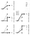
- FIG. 2 conceptually illustrates an L2 handover procedure according to an exemplary embodiment of the present invention.
- three E-RANs A, B and C belong to the same E-CN.
- a UE is connected to an E-CN via E-RAN A in step 1.
- the UE moves to E-RAN B
- the UE performs L2 handover and is connected to the E-CN via E-RAN B and E-RAN A.
- the UE is connected to the E-CN via E-RAN B in step 3.
- the UE performs L2 handover and is connected to the E-CN via E-RAN C and E-RAN B in step 4.
- the UE is connected to the E-CN via E-RAN C in step 5.
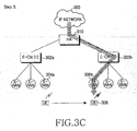
- FIGs. 3A ⁇ 3C conceptually illustrates an L3 handover procedure according to an exemplary embodiment of the present invention.
- an old E-CN 302a and a new E-CN 302b are connected to an IP network 300 under the control of the HA 310, and an old E-RAN 304a and a new E-RAN 306a are connected to the old E-CN 302a and the new E-CN 302b, respectively.
- the UE 308 moves from the old E-RAN 304a to the new E-RAN 306a, the UE 308 performs L3 handover along with L2 handover.
- step 1 the UE 308 moves from the old E-RAN 304a to the new E-RAN 306a, while the UE 308 is connected to the old E-CN 302a via the new E-RAN 306a and the old E-RAN 304a.
- a tunnel is established between the new E-RAN 306a and the old E-CN 302a, and the UE 308 is connected to the old E-CN 302a via the new E-RAN 306a and the tunnel in step 2 of FIG. 3B.
- L3 handover is completed and thus the UE 308 is connected to the new E-CN 302b via the new E-RAN 306a in step 3 of FIG. 3C.
- the UE 308 recognizes that the old E-CN 302a has been changed to the new E-CN 302b, acquires a new IP address for the L3 handover from the new E-CN 302b, and registers the new IP address to an HA and a communicating correspondent node via the new E-RAN 306a. Handover between E-CNs will be described below according to an exemplary embodiment of the present invention.
- FIG. 4 is a diagram illustrating a signal flow for performing L2 handover and L3 handover by L2 signaling according to an exemplary embodiment of the present invention.
- a UE collects information about neighbor cells and sends the cell information to an old E-RAN by a Measurement Report message in step 401.
- the Measurement Report message contains the International Mobile Station Identifier (IMSI) of the UE, an old IP address (hereinafter, referred to IPold) now in use for the UE, and cell measurements collected from the neighbor cells.
- IMSI International Mobile Station Identifier
- IPold old IP address
- the UE itself can select a target cell for L2 handover based on the cell measurements, the UE selects the target cell and notifies the old E-RAN of the target cell in a 'selected cell' field of the Measurement Report message.
- the old E-RAN Upon receipt of the Measurement Report message, the old E-RAN determines whether there is any cell providing better performance than a serving cell based on the cell information. If such a cell (that is, a target cell) is detected, the old E-RAN decides handover of the UE to the target cell in step 403. In step 405, the old E-RAN detects the IP address of the target cell.
- the old E-RAN already has knowledge of routing information about candidate cells, that is, the IP address of a new E-RAN.
- the old E-RAN receives information indicating the target cell from the UE, as described above, the old E-RAN jumps directly to step 405, without step 403.
- the old E-RAN sends a HandOver (HO) Required message to a new E-RAN that controls the L2 handover target cell.
- the HO Required message contains the IMSI and IPold of the UE and a UE context including subscriber information of the UE.
- the IPold is used as a reference value with which the new E-RAN decides whether a new IP address is to be allocated to the UE.
- the new E-RAN determines whether to allocate a new IP address to the UE based on the IPold in step 409. For example, the new E-RAN compares the prefix of the IPold with the prefix of a new CN to which the new E-RAN belongs and determines whether to allocate a new IP address to the UE, if the prefixes are different.
- the old E-RAN compares the IP address of the new E-RAN detected in step 405 with the IPold of the UE. If the IP addresses are different, the old E-RAN determines that the UE is to be allocated a new IP address. In this case, routing shall be performed between E-RANs based on the IP address.
- the new E-RAN triggers a new IP address allocation procedure of steps 411 and 415.
- the new E-RAN sends an Address Request message to a new E-CN to request for the new IP address in step 411.
- the Address Request message contains the IMSI and IPold of the UE.
- the new E-CN allocates the new IP address (hereinafter, referred to as IPnew) to the UE and stores the new IP address.
- IPnew the new IP address
- the new E-CN sends an Address Response message with the IPnew to the new E-RAN in step 415.
- the new E-RAN may include information required for generation of the UE context, for example, information about the serving E-RAN and Quality of Service (QoS) in the Address Request message.
- QoS Quality of Service
- the new E-RAN sends the IPnew to the old E-RAN by an HO Command message
- the HO Command message functions to indicate that the handover request has been accepted as well as to provide the IPnew.
- the old E-RAN adds the address of the new E-RAN (Target New E-RAN) to the HO Command message and forwards the resulting message to the UE in step 419.
- the UE determines to register the IPnew to a HA for L3 handover. Hence, the UE stores the IPnew and moves to the new E-RAN in step 421 and transmits/receives data via a communication path running from the new E-RAN through the old E-RAN to the old E-CN in step 423.
- the new E-RAN establishes an IP tunnel with the old E-CN to set up a direct communication path between them in step 425.
- the new E-RAN sends an HO Complete message indicating completion of the L2 handover to the old E-RAN in order to release the UE context information of the UE in step 427.
- the old E-RAN sends all buffered data associated with the UE to the new E-RAN and deletes the UE context associated with the UE.
- step 427 the UE sends/receives packet data through the new E-RAN and the old E-CN in step 429.
- the new E-RAN establishes an IP tunnel with the new E-CN to support L3 handover for the UE. Since step 431 occurs irrespective of the UE, step 431 may be performed at any time after step 415 where the new E-RAN acquires the IPnew of the UE.
- the UE which has received the IPnew by the HO Command message in step 419, registers the IPnew to the HA by a Binding Update Request message in step 435.
- an IP Security Association (IPSec SA) and an IPSec tunnel may be set up in order to protect the Binding Update Request message and data sent from the UE to the network.
- IPSec SA IP Security Association
- IPSec tunnel may be set up in order to protect the Binding Update Request message and data sent from the UE to the network. The setup of the IPSec tunnel will not be described in detail herein for clarity and conciseness.
- the HA updates the IPold of the UE with the IPnew in its binding cache. Then the HA notifies the UE of a normal completion of the binding update by a Binding Acknowledgement message in step 437 and sends an L3 HO Complete message to the old E-CN, notifying of completion of the L3 handover in step 439.
- the old E-CN recognizes that the UE has handed over to the new E-CN and deletes the UE context of the UE. If the information for generation of the UE context has not been provided to the new E-CN yet, the old E-CN may forward the UE context information of the UE iu the new E-CN, after receiving the L3 HO Complete message.
- the UE has completed the L2 and L3 handovers and sends/receives packet data through the new E-RAN and the new E-CN.
- FIG. 5 is a flowchart illustrating a UE operation according to an exemplary embodiment of the present invention.
- the UE collects information about candidate cells during packet transmission/reception in step 501.
- the UE sends a Measurement Report message including the IMSI and IPold of the UE and the cell information to the old E-RAN periodically or when a predetermined condition is fulfilled.
- the Measurement Report message contains information indicating a UE-selected target cell for L2 handover as well as the IPold and IMSI of the UE.
- the UE receives a HO Command message in response to the Measurement Report message from the old E-RAN.
- the HO Command message may contain an IPnew allocated to the UE and the address of the new E-RAN that controls the target cell. If the new E-RAN does not belong to the new E-CN, the HO Command message does not have the IPnew.
- the UE checks the presence or absence of the IPnew in the HO Command message in step 511. In the absence of the IPnew, the UE stores the information included in the HO Command message such as the address of the new E-RAN in step 525 and performs L2 handover in step 527. Thus, the UE is now able to send/receive packet data through the old E-CN, the old E-RAN, and the new E-RAN.
- the UE In the presence of the IPnew in the HO Command message, the UE recognizes that L3 handover as well L2 handover is required. Then the UE stores the IPnew and the address of the new E-RAN in step 513 and performs the L2 handover to the new E-RAN in step 515. Then the UE proceeds to step 519 to register the IPnew to the HA without an additional IP address acquisition procedure from the new E-CN.
- the UE may establish an IPSec SA and an IPSec tunnel with the HA, if a security mechanism is used for protecting L3 handover messages and IP packet data.
- the IPSec-associated procedure will not be shown and described herein for clarity and conciseness.
- the UE sends a Binding Update message to the HA.
- the Binding Update message contains a Home Address (HoA) allocated by the HA and the IPnew allocated by the new E-CN.
- the HoA is a fixed IP address permanent to the UE or valid for a predetermined period of time.
- the UE receives a Binding Acknowledgement message from the HA. Then the UE sends an L3 HO Complete message to the old E-CN in order to notify of completion of the L3 handover and trigger deletion of a UE context for the UE in step 523. Accordingly, the L2 and L3 handovers are completed and the UE continues packet transmission and reception through the new E-RAN and the new E-CN without passing through the old E-RAN.
- An E-Ran analyzes messages received from a UE or another E-RAN. Upon receipt of a Measurement Report message, the E-RAN operates as an old E-RAN. Upon receipt of an HO Request message containing the IPold of a UE from another E-RAN, the E-RAN operates as a new E-RAN. The operations of the old and new E-RANs will be described below separately.
- FIG. 6 is a flowchart illustrating an old E-RAN operation according to an exemplary embodiment of the present invention.
- the old E-RAN receives a Measurement Report message from the UE in step 602 and determines whether to perform L2 handover based on cell information included in the Measurement Report message in step 604. If the Measurement Report message includes information about measurements of candidate cells done by the UE, the old E-RAN decides whether to perform the L2 handover. Therefore, the old E-RAN compares a current radio performance with the radio performances of the candidate cells in step 606. If any candidate cell offering better performance than the current radio performance exists, the old E-RAN selects the candidate cell as a target cell and proceeds to step 608.
- the old E-RAN In the absence of a candidate cell offering better performance than the old E-RAN, the old E-RAN returns to step 602 and awaits reception of another Measurement Report message. On the other hand, if the Measurement Report message includes information indicating a UE-selected target cell, the old E-RAN jumps from step 604 to step 608.
- the old E-RAN detects the routable address of the new E-RAN that serves the target cell.
- the old E-RAN then sends a HO Required message to the new E-RAN in step 610.
- the HO Required message contains the IMSI, IPold, and UE context information of the UE.
- the old E-RAN receives a HO Command message from the new old E-RAN in response for the HO Required message in step 612. If the HO Command message includes the IPnew of the UE along with other information for use in the new E-CN, this implies that L3 handover is required. On the other hand, if the HO Command message does not have the IPnew, this implies that the L3 handover is not needed.
- the old E-RAN forwards the HO Command message attached with the address of the new E-RAN to the UE.
- the old E-RAN receives a L2 HO Complete message from the UE in step 616 and deletes a UE context for the UE in step 618.
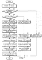
- FIG. 7 is a flowchart illustrating a new E-RAN operation according to an exemplary embodiment of the present invention.
- the new E-RAN receives a HO Required message from the old E-RAN in step 702 and determines whether to accept the L2 handover request for the UE in step 704. If the L2 handover request cannot be accepted, the new E-RAN sends a HO Fail message with a cause value indicating the reason for rejecting the L2 handover request to the old E-RAN in step 734 and then terminates the handover procedure.
- the new E-RAN determines whether an IPnew is needed for the UE based on the IPold of the UE set in the HO Required message. In an exemplary implementation, if the prefix of the IPold is different from the prefix of the IP address of the new E-CN connected to the new E-RAN by a dedicated link, the new E-RAN determines that the IPnew is needed for the UE. In an exemplary embodiment of the present invention, the old E-RAN performs step 706 instead of the new E-RAN. That is, the old E-RAN determines whether the IPnew is needed for the UE based on the prefix of the IP address associated with the new E-RAN and the IPold of the UE. If the IPnew is required, the old E-RAN inserts an indication requesting the IPnew of the UE in the HO Required message to be sent to the new E-RAN.
- the new E-RAN If determining that the IPnew is required for the UE in step 706 or based on the indication received from the old E-RAN, the new E-RAN stores the IMSI, IPold and UE context information of the UE in step 708 and requests the IPnew to the new E-CN connected to the new E-RAN by the dedicated link by an Address Request message in step 710.
- the Address Request message includes the IMSI and IPold of the UE.
- the new E-RAN receives an Address Response message including the IPnew allocated by the new E-CN in step 712.
- the new E-RAN provides the IPnew and information required for the L2 handover of the UE to the old E-RAN by a HO Command message.
- the new E-RAN sends the Identification (ID) of the new E-RAN and part of QoS information to the new E-CN in order to enable the new E-CN to generate a UE context for the UE in advance.
- the new E-CN generates a draft UE context based on the information included in the Address Request message.
- the UE context information is forwarded from the old E-CN to the new E-CN by a predetermined control message after step 714 in which the L3 handover is completed.
- the UE acquires the routable address information of the new E-CN beforehand.
- the new E-RAN After sending the HO Command message to the old E-RAN, the new E-RAN detects the movement of the UE by the L2 handover in step 716. Meanwhile, the new E-RAN establishes a tunnel for direct data communication with the old E-CN separately from a data communication path via the old E-RAN and the old E-CN in step 718. After the tunneling between the new E-RAN and the old E-CN, the new E-RAN sends an L2 HO Complete message to the old E-RAN in step 720. The L2 HO Complete message is used to notify of completion of the L2 handover and trigger deletion of a UE context for the UE.
- the new E-RAN establishes a data tunnel with the new E-CN, for transmission of L3 messages of the UE.
- This tunnel may be established at any time after the new E-RAN acquires the IPnew of the UE, irrespective of the operation of the UE.
- the new E-RAN stores the information of the UE set in the HO Required message in step 724 and sends a HO command message containing information required for the L2 handover of the UE in step 726.
- the new E-RAN detects the movement of the UE by the L2 handover in step 728, establishes a tunnel with the old E-CN in step 730, and sends an L2 HO Complete message to the old E-RAN in step 732.
- the L2 handover procedure is completed.
- a UE is notified that L3 handover will follow L2 handover by providing the UE with information required for L3 handover between CNs by an L2 signaling message used for L2 handover between RANs.
- an additional step for acquiring control information needed for the L3 handover in the UE is not performed. Accordingly, fast L3 handover can be provided.
Abstract
Description
- The present invention relates generally to a packet-switched network. More particularly, the present invention relates to a method and apparatus for simultaneously performing Layer 2 (L2) handover between Radio Access Networks (RANs) and Layer 3 (L3) handover between Core Networks (CNs) for handover between CN entities.
- Universal Mobile Telecommunication System (UMTS), an asynchronous 3rd Generation (3G) mobile communication system based on European Global System for Mobile communications (GSM) and General Packet Radio Services (GPRS) and operating in Wideband Code Division Multiple Access (WCDMA), provides a uniform service of sending packet text, digital voice or video, and multimedia data at or above 2Mbps to mobile users or computer users irrespective of their locations. With an introduction of a concept of virtual access, UMTS enables access to any end point within a network. The virtual access refers to packet-switched connection using a packet protocol like Internet Protocol (IP).
- Compared to the UMTS system where network entities are connected in Asynchronous Transfer Mode (ATM) and connected to an external packet data network via a gateway node (that is, Gateway GPRS Support Node (GGSN), Enhanced-UMTS (E-UMTS) offers IP-based connectivity between network entities, thereby reducing the number of intermediate nodes via which a User Equipment (UE) is connected to the packet data network and thus enables fast data transmission.
- A typical UMTS system is comprised of RANs and a CN. The RAN takes charge of Layer 1 (L1) and L2 protocols and is wirelessly connected to UEs. The CN takes charge of the L3 protocol and connects the RAN to an external network. The UMTS system provides L2 handover through Serving Radio Network System (SRNS) reallocation and L3 handover through inter-Serving GPRS Support Node (inter-SGSN) handover.
- Typical L2 and L3 handover schemes do not support IP address mobility because a UE moving between CN entities is not identified by its IP address. IP address version 6 (IPv6) technology proposed by the Internet Engineering Task Force (IETF) allocates and configures IP addresses by the Ethernet-based L3 network control protocol. Therefore, an active operation of an IP control protocol based on Ethernet over which messages are broadcast is not ensured in the E-UMTS network in which control information is delivered only in a dedicated path between a UE and the network. Moreover, L3 handover suffers a long delay and large packet loss.
- Accordingly, there is a need for improved handover between Core Network entities in a packet-switched network.
- An aspect of exemplary embodiments of the present invention is to address at least the above problems and/or disadvantages and to provide at least the advantages described below. Accordingly, an aspect of exemplary embodiments of the present invention is to provide a method for performing fast and seamless handover between CN entities in a packet-switched network developed from a 3G mobile communication system.
- According to one aspect of exemplary embodiments of the present invention, in a handover method between CNs in a packet-switched network having a plurality of RANs accessible to a UE and CNs for connecting the RANs to an external network over IP, when a UE connected to an old CN through an old RAN moves to a new RAN belonging to a new CN, the old RAN sends a handover required message to the new RAN. The new RAN acquires a new IP address for the UE from the new CN in response to the handover required message and sends a handover command message including the new IP address to the old RAN. The old RAN inserts an address of the new RAN in the handover command message and forwards the handover command message with the address of the new RAN to the UE. The UE performs an inter-RAN handover in response to the handover command message, thereby communicating with the old CN through the new RAN. The UE then performs an inter-CN handover based on the new IP address included in the handover command message, thereby communicating with the new CN through the new RAN.
- According to another aspect of exemplary embodiments of the present invention, in an apparatus for performing handover between CNs in a packet-switched network, an old RAN belonging to an old CN receives a measurement report message requesting handover from a UE, generates a handover required message according to the measurement report message, receives a handover command message including a new IP address for the UE, and sending the new IP address to the UE. A new RAN belonging to a new CN acquires the new IP address for the UE in response to the handover required message and sends the handover command message with the new IP address to the old RAN. The UE performs an inter-RAN handover in response to the handover command message, thereby communicating with the old CN through the new RAN by the UE, and performing an inter-CN handover based on the new IP address included in the handover command message, thereby communicating with the new CN through the new RAN.
- Other objects, advantages, and salient features of the invention will become apparent to those skilled in the art from the following detailed description, which, taken in conjunction with the annexed drawings, discloses exemplary embodiments of the invention.
- The above and other objects, features and advantages of certain exemplary embodiments of the present invention will be more apparent from the following detailed description taken in conjunction with the accompanying drawings, in which:
- FIG. 1 illustrates a network configuration according to an exemplary embodiment of the present invention;
- FIG. 2 conceptually illustrates an L2 handover procedure according to an exemplary embodiment of the present invention;
- FIGs. 3A - 3C conceptually illustrate an L3 handover procedure according to an exemplary embodiment of the present invention;
- FIG. 4 is a diagram illustrating a signal flow for performing L2 handover and L3 handover by L2 signaling according to an exemplary embodiment of the present invention;
- FIG. 5 is a flowchart illustrating a UE operation according to an exemplary embodiment of the present invention;
- FIG. 6 is a flowchart illustrating an old E-RAN operation according to an exemplary embodiment of the present invention; and
- FIG. 7 is a flowchart illustrating a new E-RAN operation according to an exemplary embodiment of the present invention.
- Throughout the drawings, the same drawing reference numerals will be understood to refer to the same elements, features, and structures.
- The matters defined in the description such as a detailed construction and elements are provided to assist in a comprehensive understanding of exemplary embodiments of the invention. Accordingly, those of ordinary skill in the art will recognize that various changes and modifications of the embodiments described herein can be made without departing from the scope and spirit of the invention. Also, descriptions of well-known functions and constructions are omitted for clarity and conciseness.
- The present invention is intended to enable handover between network entities, ensuring IP address mobility of a UE by sending IP address control information to the UE by an L2 signaling message from an ATM-based control plane, rather than by an IP control protocol such as Internet Control Message Protocol (ICMP). A description will be made herein of exemplary embodiments of the present invention in which L3 control information, for example, IP layer control information required for L3 handover is sent by an L2 signaling message.
- When moving between RANs within the same CN, the UE performs L2 handover, while when moving between RANs belonging to different CNs, the UE performs L2 handover and L3 handover successively. In the latter case, information for the L3 handover (for example, IP address or new CN address) is included in the L2 signaling message sent to the UE for the L2 handover. Thus the UE performs the L3 handover to a new CN based on the information set in the L2 signaling message.
- FIG. 1 illustrates a network configuration according to an exemplary embodiment of the present invention. The network configuration includes a packet-switched network developed from a 3G mobile communication system and the present invention is applicable to a 3G Long Term Evolution (LTE) network, that is, an Evolution/Enhanced network.
- Referring to FIG. 1, the network includes a plurality of Enhanced-Core Networks (E-CNs) 102a and 102b which are connected to an
IP network 100 under the control of a Home Agent (HA) 110, and a plurality of Enhanced-Radio Access Networks (E-RANs) 104 and 106 connected to theE-CNs HA 110. A plurality of Wireless Local Area Network (WLAN) Access Gateways (WAGs) 114 is connected to thePDG 112, and a plurality of Access Points (APs) 116 is connected to each of theWAGs 114. While theHA 110 is shown as a physically independent entity, theHA 110 may be configured to be a logical entity included in theE-CNs - During moving from the E-RAN 104a belonging to the
E-CN 102a to theE-RAN 106a belonging to theE-CN 102b, a UE 108 performs L2 handover and L3 handover simultaneously. When a UE 118 moves from the E-RAN 106b to the AP 116a belonging to thePDG 112, the UE 118 also performs L2 handover and L3 handover simultaneously. The L2 handover is carried out by a known WLAN L2 protocol. The following description is made of an operation of the UE 108 for handover between theE-CNs - The UE 108 receives cell information from accessible cells and sends the cell information to the
E-RAN 104a or decides whether to perform an L2 handover to a target cell based on the cell information. Also, the UE 108 stores an IP address allocated by the E-CN 102a. When acquiring a new IP address from theE-CN 102b, the UE 108 triggers an L3 handover procedure for IP address mobility. - The E-RAN 104a determines whether to perform the L2 handover for the UE 108 and may determine the routable address of the target cell based on the cell information. The E-RANs 104a and 106a may request a new IP address to the
E-CN 102b for the UE 108, considering that the new IP address is needed for the UE 108. TheE-RAN 106a may establish a tunnel between theE-CN 102a and the E-CN 102b for the UE 108. - In the case of handover between E-CNs requiring concurrent L2 and L3 handovers, the L3 handover can be efficiently supported by L2 signaling. For this purpose, L3 control information is sent to the UE by a L2 signaling message from a control plane in an exemplary embodiment of the present invention.
- FIG. 2 conceptually illustrates an L2 handover procedure according to an exemplary embodiment of the present invention. In the illustrated case of three E-RANs A, B and C belong to the same E-CN.
- Referring to FIG. 2, a UE is connected to an E-CN via E-RAN A in
step 1. Instep 2, As the UE moves to E-RAN B, the UE performs L2 handover and is connected to the E-CN via E-RAN B and E-RAN A. After the L2 handover, the UE is connected to the E-CN via E-RAN B instep 3. As the UE moves to E-RAN C, the UE performs L2 handover and is connected to the E-CN via E-RAN C and E-RAN B in step 4. After the L2 handover, the UE is connected to the E-CN via E-RAN C in step 5. - FIGs. 3A ― 3C conceptually illustrates an L3 handover procedure according to an exemplary embodiment of the present invention. In FIGs. 3A ― 3C, an
old E-CN 302a and anew E-CN 302b are connected to anIP network 300 under the control of theHA 310, and an old E-RAN 304a and anew E-RAN 306a are connected to theold E-CN 302a and thenew E-CN 302b, respectively. As aUE 308 moves from theold E-RAN 304a to thenew E-RAN 306a, theUE 308 performs L3 handover along with L2 handover. - Referring to FIG. 3A, in
step 1, theUE 308 moves from theold E-RAN 304a to thenew E-RAN 306a, while theUE 308 is connected to theold E-CN 302a via thenew E-RAN 306a and theold E-RAN 304a. A tunnel is established between thenew E-RAN 306a and theold E-CN 302a, and theUE 308 is connected to theold E-CN 302a via thenew E-RAN 306a and the tunnel instep 2 of FIG. 3B. L3 handover is completed and thus theUE 308 is connected to thenew E-CN 302b via thenew E-RAN 306a instep 3 of FIG. 3C. - During the handover between the E-CNs illustrated in FIGs. 3A - 3C, the
UE 308 recognizes that theold E-CN 302a has been changed to thenew E-CN 302b, acquires a new IP address for the L3 handover from thenew E-CN 302b, and registers the new IP address to an HA and a communicating correspondent node via thenew E-RAN 306a. Handover between E-CNs will be described below according to an exemplary embodiment of the present invention. - FIG. 4 is a diagram illustrating a signal flow for performing L2 handover and L3 handover by L2 signaling according to an exemplary embodiment of the present invention.
- Referring to FIG. 4, a UE collects information about neighbor cells and sends the cell information to an old E-RAN by a Measurement Report message in
step 401. The Measurement Report message contains the International Mobile Station Identifier (IMSI) of the UE, an old IP address (hereinafter, referred to IPold) now in use for the UE, and cell measurements collected from the neighbor cells. - In an exemplary implementation, it can be further contemplated that if the UE itself can select a target cell for L2 handover based on the cell measurements, the UE selects the target cell and notifies the old E-RAN of the target cell in a 'selected cell' field of the Measurement Report message.
- Upon receipt of the Measurement Report message, the old E-RAN determines whether there is any cell providing better performance than a serving cell based on the cell information. If such a cell (that is, a target cell) is detected, the old E-RAN decides handover of the UE to the target cell in
step 403. In step 405, the old E-RAN detects the IP address of the target cell. The old E-RAN already has knowledge of routing information about candidate cells, that is, the IP address of a new E-RAN. - If the old E-RAN receives information indicating the target cell from the UE, as described above, the old E-RAN jumps directly to step 405, without
step 403. - In step 407, the old E-RAN sends a HandOver (HO) Required message to a new E-RAN that controls the L2 handover target cell. The HO Required message contains the IMSI and IPold of the UE and a UE context including subscriber information of the UE. The IPold is used as a reference value with which the new E-RAN decides whether a new IP address is to be allocated to the UE. Upon receipt of the HO Required message, the new E-RAN determines whether to allocate a new IP address to the UE based on the IPold in
step 409. For example, the new E-RAN compares the prefix of the IPold with the prefix of a new CN to which the new E-RAN belongs and determines whether to allocate a new IP address to the UE, if the prefixes are different. - In an exemplary implementation, the old E-RAN compares the IP address of the new E-RAN detected in step 405 with the IPold of the UE. If the IP addresses are different, the old E-RAN determines that the UE is to be allocated a new IP address. In this case, routing shall be performed between E-RANs based on the IP address. When the IPold of the UE is included in the HO Required message requesting L2 handover sent from the old E-RAN, the new E-RAN triggers a new IP address allocation procedure of
steps - In the case where a new IP address is required for the UE requesting the L2 handover, the new E-RAN sends an Address Request message to a new E-CN to request for the new IP address in
step 411. The Address Request message contains the IMSI and IPold of the UE. The new E-CN allocates the new IP address (hereinafter, referred to as IPnew) to the UE and stores the new IP address. Then the new E-CN sends an Address Response message with the IPnew to the new E-RAN instep 415. To enable the new E-CN to generate a UE context for the UE in advance, the new E-RAN may include information required for generation of the UE context, for example, information about the serving E-RAN and Quality of Service (QoS) in the Address Request message. - In
step 417, the new E-RAN sends the IPnew to the old E-RAN by an HO Command message The HO Command message functions to indicate that the handover request has been accepted as well as to provide the IPnew. The old E-RAN adds the address of the new E-RAN (Target New E-RAN) to the HO Command message and forwards the resulting message to the UE instep 419. - If the HO Command message includes the IPnew, the UE determines to register the IPnew to a HA for L3 handover. Hence, the UE stores the IPnew and moves to the new E-RAN in step 421 and transmits/receives data via a communication path running from the new E-RAN through the old E-RAN to the old E-CN in
step 423. - Meanwhile, the new E-RAN establishes an IP tunnel with the old E-CN to set up a direct communication path between them in step 425. After the tunneling, the new E-RAN sends an HO Complete message indicating completion of the L2 handover to the old E-RAN in order to release the UE context information of the UE in
step 427. The old E-RAN sends all buffered data associated with the UE to the new E-RAN and deletes the UE context associated with the UE. - When the L2 handover is completed in
step 401 throughstep 427, the UE sends/receives packet data through the new E-RAN and the old E-CN instep 429. In step 431, the new E-RAN establishes an IP tunnel with the new E-CN to support L3 handover for the UE. Since step 431 occurs irrespective of the UE, step 431 may be performed at any time afterstep 415 where the new E-RAN acquires the IPnew of the UE. - The UE, which has received the IPnew by the HO Command message in
step 419, registers the IPnew to the HA by a Binding Update Request message in step 435. Before sending the Binding Update Request message, an IP Security Association (IPSec SA) and an IPSec tunnel may be set up in order to protect the Binding Update Request message and data sent from the UE to the network. The setup of the IPSec tunnel will not be described in detail herein for clarity and conciseness. - The HA updates the IPold of the UE with the IPnew in its binding cache. Then the HA notifies the UE of a normal completion of the binding update by a Binding Acknowledgement message in step 437 and sends an L3 HO Complete message to the old E-CN, notifying of completion of the L3 handover in step 439. Thus the old E-CN recognizes that the UE has handed over to the new E-CN and deletes the UE context of the UE. If the information for generation of the UE context has not been provided to the new E-CN yet, the old E-CN may forward the UE context information of the UE iu the new E-CN, after receiving the L3 HO Complete message. In
step 441, the UE has completed the L2 and L3 handovers and sends/receives packet data through the new E-RAN and the new E-CN. - FIG. 5 is a flowchart illustrating a UE operation according to an exemplary embodiment of the present invention.
- Referring to FIG. 5, the UE collects information about candidate cells during packet transmission/reception in
step 501. Instep 505, the UE sends a Measurement Report message including the IMSI and IPold of the UE and the cell information to the old E-RAN periodically or when a predetermined condition is fulfilled. In an exemplary implementation, it can be further contemplated that the Measurement Report message contains information indicating a UE-selected target cell for L2 handover as well as the IPold and IMSI of the UE. - In
step 509, the UE receives a HO Command message in response to the Measurement Report message from the old E-RAN. The HO Command message may contain an IPnew allocated to the UE and the address of the new E-RAN that controls the target cell. If the new E-RAN does not belong to the new E-CN, the HO Command message does not have the IPnew. The UE checks the presence or absence of the IPnew in the HO Command message instep 511. In the absence of the IPnew, the UE stores the information included in the HO Command message such as the address of the new E-RAN instep 525 and performs L2 handover instep 527. Thus, the UE is now able to send/receive packet data through the old E-CN, the old E-RAN, and the new E-RAN. - In the presence of the IPnew in the HO Command message, the UE recognizes that L3 handover as well L2 handover is required. Then the UE stores the IPnew and the address of the new E-RAN in
step 513 and performs the L2 handover to the new E-RAN instep 515. Then the UE proceeds to step 519 to register the IPnew to the HA without an additional IP address acquisition procedure from the new E-CN. - Before the IPnew registration, the UE may establish an IPSec SA and an IPSec tunnel with the HA, if a security mechanism is used for protecting L3 handover messages and IP packet data. The IPSec-associated procedure will not be shown and described herein for clarity and conciseness.
- In
step 519, the UE sends a Binding Update message to the HA. The Binding Update message contains a Home Address (HoA) allocated by the HA and the IPnew allocated by the new E-CN. The HoA is a fixed IP address permanent to the UE or valid for a predetermined period of time. Instep 521, the UE receives a Binding Acknowledgement message from the HA. Then the UE sends an L3 HO Complete message to the old E-CN in order to notify of completion of the L3 handover and trigger deletion of a UE context for the UE instep 523. Accordingly, the L2 and L3 handovers are completed and the UE continues packet transmission and reception through the new E-RAN and the new E-CN without passing through the old E-RAN. - The operations of the E-RANs will now be described. An E-Ran analyzes messages received from a UE or another E-RAN. Upon receipt of a Measurement Report message, the E-RAN operates as an old E-RAN. Upon receipt of an HO Request message containing the IPold of a UE from another E-RAN, the E-RAN operates as a new E-RAN. The operations of the old and new E-RANs will be described below separately.
- FIG. 6 is a flowchart illustrating an old E-RAN operation according to an exemplary embodiment of the present invention.
- Referring to FIG. 6, during packet communication with the UE, the old E-RAN receives a Measurement Report message from the UE in
step 602 and determines whether to perform L2 handover based on cell information included in the Measurement Report message instep 604. If the Measurement Report message includes information about measurements of candidate cells done by the UE, the old E-RAN decides whether to perform the L2 handover. Therefore, the old E-RAN compares a current radio performance with the radio performances of the candidate cells instep 606. If any candidate cell offering better performance than the current radio performance exists, the old E-RAN selects the candidate cell as a target cell and proceeds to step 608. In the absence of a candidate cell offering better performance than the old E-RAN, the old E-RAN returns to step 602 and awaits reception of another Measurement Report message. On the other hand, if the Measurement Report message includes information indicating a UE-selected target cell, the old E-RAN jumps fromstep 604 to step 608. - In
step 608, the old E-RAN detects the routable address of the new E-RAN that serves the target cell. The old E-RAN then sends a HO Required message to the new E-RAN instep 610. The HO Required message contains the IMSI, IPold, and UE context information of the UE. The old E-RAN receives a HO Command message from the new old E-RAN in response for the HO Required message instep 612. If the HO Command message includes the IPnew of the UE along with other information for use in the new E-CN, this implies that L3 handover is required. On the other hand, if the HO Command message does not have the IPnew, this implies that the L3 handover is not needed. - In step 614, the old E-RAN forwards the HO Command message attached with the address of the new E-RAN to the UE. The old E-RAN receives a L2 HO Complete message from the UE in
step 616 and deletes a UE context for the UE instep 618. - FIG. 7 is a flowchart illustrating a new E-RAN operation according to an exemplary embodiment of the present invention.
- Referring to FIG. 7, the new E-RAN receives a HO Required message from the old E-RAN in
step 702 and determines whether to accept the L2 handover request for the UE instep 704. If the L2 handover request cannot be accepted, the new E-RAN sends a HO Fail message with a cause value indicating the reason for rejecting the L2 handover request to the old E-RAN instep 734 and then terminates the handover procedure. - If the L2 handover request is accepted, the new E-RAN determines whether an IPnew is needed for the UE based on the IPold of the UE set in the HO Required message. In an exemplary implementation, if the prefix of the IPold is different from the prefix of the IP address of the new E-CN connected to the new E-RAN by a dedicated link, the new E-RAN determines that the IPnew is needed for the UE. In an exemplary embodiment of the present invention, the old E-RAN performs
step 706 instead of the new E-RAN. That is, the old E-RAN determines whether the IPnew is needed for the UE based on the prefix of the IP address associated with the new E-RAN and the IPold of the UE. If the IPnew is required, the old E-RAN inserts an indication requesting the IPnew of the UE in the HO Required message to be sent to the new E-RAN. - If determining that the IPnew is required for the UE in
step 706 or based on the indication received from the old E-RAN, the new E-RAN stores the IMSI, IPold and UE context information of the UE instep 708 and requests the IPnew to the new E-CN connected to the new E-RAN by the dedicated link by an Address Request message instep 710. The Address Request message includes the IMSI and IPold of the UE. Instep 712, the new E-RAN receives an Address Response message including the IPnew allocated by the new E-CN instep 712. - In
step 714, the new E-RAN provides the IPnew and information required for the L2 handover of the UE to the old E-RAN by a HO Command message. In an exemplary embodiment of the present invention, the new E-RAN sends the Identification (ID) of the new E-RAN and part of QoS information to the new E-CN in order to enable the new E-CN to generate a UE context for the UE in advance. In this case, the new E-CN generates a draft UE context based on the information included in the Address Request message. In an exemplary implementation, it can be further contemplated that the UE context information is forwarded from the old E-CN to the new E-CN by a predetermined control message afterstep 714 in which the L3 handover is completed. For this purpose, the UE acquires the routable address information of the new E-CN beforehand. - After sending the HO Command message to the old E-RAN, the new E-RAN detects the movement of the UE by the L2 handover in
step 716. Meanwhile, the new E-RAN establishes a tunnel for direct data communication with the old E-CN separately from a data communication path via the old E-RAN and the old E-CN instep 718. After the tunneling between the new E-RAN and the old E-CN, the new E-RAN sends an L2 HO Complete message to the old E-RAN instep 720. The L2 HO Complete message is used to notify of completion of the L2 handover and trigger deletion of a UE context for the UE. Instep 722, the new E-RAN establishes a data tunnel with the new E-CN, for transmission of L3 messages of the UE. This tunnel may be established at any time after the new E-RAN acquires the IPnew of the UE, irrespective of the operation of the UE. - On the contrary, if there is no need for allocating the IPnew to the UE according to the HO Required message, that is, if the prefix of the IPold is identical to that of the new E-CN, the new E-RAN stores the information of the UE set in the HO Required message in
step 724 and sends a HO command message containing information required for the L2 handover of the UE instep 726. The new E-RAN detects the movement of the UE by the L2 handover instep 728, establishes a tunnel with the old E-CN instep 730, and sends an L2 HO Complete message to the old E-RAN instep 732. Thus, the L2 handover procedure is completed. - In accordance with the exemplary embodiments of the present invention as described above, a UE is notified that L3 handover will follow L2 handover by providing the UE with information required for L3 handover between CNs by an L2 signaling message used for L2 handover between RANs. Thus, an additional step for acquiring control information needed for the L3 handover in the UE is not performed. Accordingly, fast L3 handover can be provided.
- While the invention has been shown and described with reference to certain exemplary embodiments thereof, it will be understood by those skilled in the art that various changes in form and details may be made therein without departing from the spirit and scope of the invention as defined by the appended claims.
Claims (15)
- A handover method between Core Networks (CNs) in a packet-switched network having a plurality of Radio Access Networks (RANs) accessible to a User Equipment (UE) and CNs for connecting the RANs to an external network over Internet Protocol (IP), comprising:sending a handover required message from an old RAN to a new RAN when a UE connected to an old CN through the oid RAN moves to the new RAN belonging to a new CN;acquiring a new IP address for the UE from the new CN in response to the handover required message by the new RAN;sending a handover command message including the new IP address from the new RAN to the old RAN;inserting an address of the new RAN in the handover command message and forwarding the handover command message with the address of the new RAN to the UE by the old RAN;performing an inter-RAN handover in response to the handover command message and communicating with the old CN through the new RAN by the UE; andperforming an inter-CN handover based on the new IP address included in the handover command message and communicating with the new CN through the new RAN by the UE.
- The handover method of claim 1, further comprising:establishing a tunnel with the old CN by the new RAN and sending a handover complete message to the old RAN, after sending the handover command message to the UE; anddeleting a context associated with the UE in response to the handover complete message by the old RAN.
- The handover method of claim 1, further comprising establishing a tunnel with the new CN for delivering data associated with the UE by the new RAN, after acquiring the new IP address.
- The handover method of claim 1, further comprising registering the new IP address to a Home Agent (HA) associated with the UE by the UE, after receiving the handover command message.
- The handover method of claim 4, further comprising:sending a handover complete message to the old CN by the UE, after registering the new IP address; anddeleting the context associated with the UE in response to the handover complete message by the old CN.
- An apparatus for performing handover between Core Networks (CNs) in a packet-switched network, comprising:an old Radio Access Network (RAN) belonging to an old CN, for receiving a measurement report message requesting handover from a user equipment (UE), generating a handover required message according to the measurement report message, receiving a handover command message including a new Internet Protocol (IP) address for the UE, and sending the new IP address to the UE; anda new RAN belonging to a new CN, for acquiring the new IP address for the UE in response to the handover required message and sending the handover command message with the new IP address to the old RAN,wherein the UE performs an inter-RAN handover in response to the handover command message, thereby communicating with the old CN through the new RAN by the UE, and performing an inter-CN handover based on the new IP address included in the handover command message, thereby communicating with the new CN through the new RAN.
- The apparatus of claim 6, wherein the new RAN establishes a tunnel with the old CN after sending the handover command message to the UE, and sends a handover complete message to the old RAN, and the old RAN deletes a context associated with the UE in response to the handover complete message.
- The apparatus of claim 6, wherein the new RAN establishes a tunnel with the new CN for delivering data associated with the UE, after acquiring the new IP address.
- The apparatus of claim 6, wherein the UE registers the new IP address to a Home Agent (HA) associated with the UE, after receiving the handover command message.
- The apparatus of claim 9, wherein the UE sends a handover complete message to the old CN, after registering the new IP address, and the old CN deletes the context associated with the UE in response to me handover complete message.
- A handover method between Core Networks (CNs) in a packet-switched network, comprising:receiving a measurement report message by an old Radio Access Network (RAN) comprised in an old Core Network (CN) requesting handover from user equipment (UE);generating a handover required message according to the measurement report message;receiving a handover command message comprising a new Internet Protocol (IP) address for the UE;sending the new IP address to the UE;sending a handover required message from the old RAN to a new RAN when the UE connected to an old CN through the old RAN moves to the new RAN belonging to a new CN;acquiring a new IP address for the UE from the new CN in response to the handover required message by the new RAN;sending a handover command message including the new IP address from the new RAN to the old RAN;inserting an address of the new RAN in the handover command message and forwarding the handover command message with the address of the new RAN to the UE by the old RAN;performing an inter-RAN handover in response to the handover command message and communicating with the old CN through the new RAN by the UE; andperforming an inter-CN handover based on the new IP address included in the handover command message and communicating with the new CN through the new RAN by the UE.
- The handover method of claim 11, further comprising:establishing a tunnel with the old CN by the new RAN and sending a handover complete message to the old RAN, after sending the handover command message to the UE; anddeleting a context associated with the UE in response to the handover complete message by the old RAN.
- The handover method of claim 11, further comprising establishing a tunnel with the new CN for delivering data associated with the UE by the new RAN, after acquiring the new IP address.
- The handover method of claim 11, further comprising registering the new IP address to a Home Agent (HA) associated with the UE by the UE, after receiving the handover command message.
- The handover method of claim 14, further comprising:sending a handover complete message to the old CN by the UE, after registering the new IP address; anddeleting the context associated with the UE in response to the handover complete message by the old CN.
Applications Claiming Priority (1)
| Application Number | Priority Date | Filing Date | Title |
|---|---|---|---|
| KR1020050064363A KR100744374B1 (en) | 2005-07-15 | 2005-07-15 | Handover method between core network entities in packet-switched based network and therefor apparatus |
Publications (2)
| Publication Number | Publication Date |
|---|---|
| EP1744582A1 true EP1744582A1 (en) | 2007-01-17 |
| EP1744582B1 EP1744582B1 (en) | 2008-11-19 |
Family
ID=37116021
Family Applications (1)
| Application Number | Title | Priority Date | Filing Date |
|---|---|---|---|
| EP06014758A Active EP1744582B1 (en) | 2005-07-15 | 2006-07-14 | Method and aparatus for performing handover between core network entities in a packet-swiched network |
Country Status (7)
| Country | Link |
|---|---|
| US (1) | US20070041346A1 (en) |
| EP (1) | EP1744582B1 (en) |
| JP (1) | JP2009500980A (en) |
| KR (1) | KR100744374B1 (en) |
| CN (1) | CN101223741A (en) |
| DE (1) | DE602006003690D1 (en) |
| WO (1) | WO2007011137A1 (en) |
Cited By (2)
| Publication number | Priority date | Publication date | Assignee | Title |
|---|---|---|---|---|
| WO2008078632A1 (en) | 2006-12-26 | 2008-07-03 | Panasonic Corporation | Communication method, communication system, home agent, and mobile node |
| EP3668183A4 (en) * | 2017-08-09 | 2020-07-29 | Vivo Mobile Communication Co., Ltd. | Mobility management method, user equipment, and network side apparatus |
Families Citing this family (21)
| Publication number | Priority date | Publication date | Assignee | Title |
|---|---|---|---|---|
| DE10243142A1 (en) * | 2002-09-17 | 2004-03-18 | Siemens Ag | Radio hand-over method for carrying out a hand-over procedure in a radio communications system maintains an active radio connection even through cell boundaries |
| US8902812B1 (en) | 2006-03-14 | 2014-12-02 | Sprint Spectrum L.P. | System and method for passive optical network backhaul |
| CN101128043B (en) | 2006-08-15 | 2011-02-02 | 华为技术有限公司 | Data processing method for switching between systems or change |
| JP4848890B2 (en) | 2006-08-23 | 2011-12-28 | 日本電気株式会社 | Mobile communication system and method, and base station used therefor |
| US20080075041A1 (en) * | 2006-09-27 | 2008-03-27 | Innovative Sonic Limited | Method and apparatus for distribution and attachment gateway support node in wireless communications system |
| US8797995B2 (en) * | 2007-01-18 | 2014-08-05 | Cisco Technology, Inc. | Device-assisted layer 3 handoff for mobile services |
| US8185107B2 (en) * | 2007-03-29 | 2012-05-22 | Marvell International Ltd. | IP address allocation in evolved wireless networks |
| CN101304600B (en) * | 2007-05-08 | 2011-12-07 | 华为技术有限公司 | Method and system for negotiating safety capability |
| US7990925B2 (en) * | 2007-05-30 | 2011-08-02 | Qualcomm Incorporated | Method and apparatus for communication handoff |
| KR100937321B1 (en) * | 2008-02-12 | 2010-01-18 | 에스케이 텔레콤주식회사 | Method for handover of mobile IP between different network |
| KR100955999B1 (en) * | 2008-02-20 | 2010-05-04 | 에스케이 텔레콤주식회사 | Method for handover of mobile IP between different network |
| US20100098021A1 (en) * | 2008-10-16 | 2010-04-22 | Cisco Technology, Inc. | Policy-driven layer 3 handoff for mobile services |
| US8902805B2 (en) * | 2008-10-24 | 2014-12-02 | Qualcomm Incorporated | Cell relay packet routing |
| CN101754305A (en) * | 2008-12-04 | 2010-06-23 | 华为技术有限公司 | Method, device and system for realizing the switching of data gateway |
| EP2404463B1 (en) * | 2009-04-21 | 2018-02-21 | LG Electronics Inc. | Method to facilitate user equipment handoff within a packet data communication system |
| US8547912B1 (en) | 2009-08-07 | 2013-10-01 | Sprint Communications Company L.P. | Mobility between two different wireless access networks |
| US8780720B2 (en) * | 2010-01-11 | 2014-07-15 | Venturi Ip Llc | Radio access network load and condition aware traffic shaping control |
| CN103338489B (en) * | 2013-06-27 | 2016-12-28 | 华为技术有限公司 | Inter-system switching method, device and network system |
| CN107734572B (en) * | 2016-08-12 | 2019-09-17 | 电信科学技术研究院 | A kind of method and apparatus of region control |
| US10568004B2 (en) * | 2017-03-23 | 2020-02-18 | Futurewei Technologies, Inc. | Layer 2 (L2) mobility for new radio (NR) networks |
| CN111615188B (en) * | 2019-02-22 | 2021-10-01 | 华为技术有限公司 | Data transmission method, device and computer storage medium |
Citations (5)
| Publication number | Priority date | Publication date | Assignee | Title |
|---|---|---|---|---|
| WO2002017670A1 (en) * | 2000-08-25 | 2002-02-28 | Nokia Corporation | jpMETHOD OF ARRANGING DATA TRANSFER IN A WIRELESS TELECOMMUNICATION SYSTEM |
| US20020141361A1 (en) * | 2001-04-03 | 2002-10-03 | Lila Madour | Mobile IP registration in selected inter-PDSN dormant hand-off cases in a CDMA2000-based cellular telecommunications network |
| US20020191562A1 (en) * | 1997-05-12 | 2002-12-19 | Kabushiki Kaisha Toshiba | Router device, datagram transfer method and communication system realizing handoff control for mobile terminals |
| US20040085931A1 (en) * | 2002-11-04 | 2004-05-06 | Ramin Rezaiifar | Method and apparatus for handoff of a wireless packet data services connection |
| US6904025B1 (en) * | 1999-10-12 | 2005-06-07 | Telefonaktiebolaget Lm Ericsson (Publ) | Wide area network mobility for IP based networks |
Family Cites Families (5)
| Publication number | Priority date | Publication date | Assignee | Title |
|---|---|---|---|---|
| FI991597A (en) * | 1999-07-12 | 2001-01-13 | Nokia Networks Oy | Access context control at a macro-level mobility control registration in an access network |
| US20030104814A1 (en) * | 2001-11-30 | 2003-06-05 | Docomo Communications Laboratories Usa | Low latency mobile initiated tunneling handoff |
| KR100483007B1 (en) * | 2002-12-24 | 2005-04-18 | 한국전자통신연구원 | Method of handover in next generation mobile telecommunication system |
| JP2006519539A (en) * | 2003-02-27 | 2006-08-24 | コーニンクレッカ フィリップス エレクトロニクス エヌ ヴィ | Method and system for improved handoff of mobile devices between wireless sub-networks |
| JP4265945B2 (en) * | 2003-08-08 | 2009-05-20 | 三菱電機株式会社 | Signaling transfer method in mobile network and mobile network |
-
2005
- 2005-07-15 KR KR1020050064363A patent/KR100744374B1/en not_active IP Right Cessation
-
2006
- 2006-07-14 JP JP2008521332A patent/JP2009500980A/en active Pending
- 2006-07-14 CN CNA2006800258318A patent/CN101223741A/en active Pending
- 2006-07-14 WO PCT/KR2006/002783 patent/WO2007011137A1/en active Application Filing
- 2006-07-14 EP EP06014758A patent/EP1744582B1/en active Active
- 2006-07-14 US US11/486,371 patent/US20070041346A1/en not_active Abandoned
- 2006-07-14 DE DE602006003690T patent/DE602006003690D1/en active Active
Patent Citations (5)
| Publication number | Priority date | Publication date | Assignee | Title |
|---|---|---|---|---|
| US20020191562A1 (en) * | 1997-05-12 | 2002-12-19 | Kabushiki Kaisha Toshiba | Router device, datagram transfer method and communication system realizing handoff control for mobile terminals |
| US6904025B1 (en) * | 1999-10-12 | 2005-06-07 | Telefonaktiebolaget Lm Ericsson (Publ) | Wide area network mobility for IP based networks |
| WO2002017670A1 (en) * | 2000-08-25 | 2002-02-28 | Nokia Corporation | jpMETHOD OF ARRANGING DATA TRANSFER IN A WIRELESS TELECOMMUNICATION SYSTEM |
| US20020141361A1 (en) * | 2001-04-03 | 2002-10-03 | Lila Madour | Mobile IP registration in selected inter-PDSN dormant hand-off cases in a CDMA2000-based cellular telecommunications network |
| US20040085931A1 (en) * | 2002-11-04 | 2004-05-06 | Ramin Rezaiifar | Method and apparatus for handoff of a wireless packet data services connection |
Cited By (3)
| Publication number | Priority date | Publication date | Assignee | Title |
|---|---|---|---|---|
| WO2008078632A1 (en) | 2006-12-26 | 2008-07-03 | Panasonic Corporation | Communication method, communication system, home agent, and mobile node |
| EP3668183A4 (en) * | 2017-08-09 | 2020-07-29 | Vivo Mobile Communication Co., Ltd. | Mobility management method, user equipment, and network side apparatus |
| EP4221332A1 (en) * | 2017-08-09 | 2023-08-02 | Vivo Mobile Communication Co., Ltd. | Mobility management method, user equipment and network side device |
Also Published As
| Publication number | Publication date |
|---|---|
| KR100744374B1 (en) | 2007-07-30 |
| DE602006003690D1 (en) | 2009-01-02 |
| US20070041346A1 (en) | 2007-02-22 |
| WO2007011137A1 (en) | 2007-01-25 |
| CN101223741A (en) | 2008-07-16 |
| JP2009500980A (en) | 2009-01-08 |
| KR20070009243A (en) | 2007-01-18 |
| EP1744582B1 (en) | 2008-11-19 |
Similar Documents
| Publication | Publication Date | Title |
|---|---|---|
| EP1744582B1 (en) | Method and aparatus for performing handover between core network entities in a packet-swiched network | |
| US9955394B2 (en) | Method and apparatus for performing handover between core network entities in a packet-switched network | |
| US8457635B2 (en) | Non-3GPP to 3GPP network handover optimizations | |
| US9491665B2 (en) | Data processing method and device | |
| EP2528277B1 (en) | Multiple protocol correlation and topology detection in eHRPD networks | |
| KR101384697B1 (en) | Method and communication entity for proving a communications connection | |
| Choi et al. | Seamless Handoff Scheme based on pre-registration and pre-authentication for UMTS–WLAN interworking | |
| Kim et al. | Integrated handoff scheme of FMIPv6 and MAC protocol in 4th generation systems | |
| Bultmann et al. | Media independent handover enabled advanced mobility management and its functional mapping | |
| Idserda | Simultaneous binding proxy mobile IPv6 | |
| Patil et al. | Integration of FMIPv6 in HMIPv6 to Improve Hand‐over Performance | |
| EP2058999A1 (en) | A method for data transmission in a communication network for multihoming | |
| Kwon et al. | Design and implementation of ARIP for efficient handovers |
Legal Events
| Date | Code | Title | Description |
|---|---|---|---|
| PUAI | Public reference made under article 153(3) epc to a published international application that has entered the european phase |
Free format text: ORIGINAL CODE: 0009012 |
|
| 17P | Request for examination filed |
Effective date: 20060714 |
|
| AK | Designated contracting states |
Kind code of ref document: A1 Designated state(s): AT BE BG CH CY CZ DE DK EE ES FI FR GB GR HU IE IS IT LI LT LU LV MC NL PL PT RO SE SI SK TR |
|
| AX | Request for extension of the european patent |
Extension state: AL BA HR MK YU |
|
| 17Q | First examination report despatched |
Effective date: 20070222 |
|
| AKX | Designation fees paid |
Designated state(s): DE FI FR GB IT SE |
|
| GRAP | Despatch of communication of intention to grant a patent |
Free format text: ORIGINAL CODE: EPIDOSNIGR1 |
|
| GRAS | Grant fee paid |
Free format text: ORIGINAL CODE: EPIDOSNIGR3 |
|
| GRAA | (expected) grant |
Free format text: ORIGINAL CODE: 0009210 |
|
| AK | Designated contracting states |
Kind code of ref document: B1 Designated state(s): DE FI FR GB IT SE |
|
| REG | Reference to a national code |
Ref country code: GB Ref legal event code: FG4D |
|
| REF | Corresponds to: |
Ref document number: 602006003690 Country of ref document: DE Date of ref document: 20090102 Kind code of ref document: P |
|
| PG25 | Lapsed in a contracting state [announced via postgrant information from national office to epo] |
Ref country code: FI Free format text: LAPSE BECAUSE OF FAILURE TO SUBMIT A TRANSLATION OF THE DESCRIPTION OR TO PAY THE FEE WITHIN THE PRESCRIBED TIME-LIMIT Effective date: 20081119 |
|
| PG25 | Lapsed in a contracting state [announced via postgrant information from national office to epo] |
Ref country code: SE Free format text: LAPSE BECAUSE OF FAILURE TO SUBMIT A TRANSLATION OF THE DESCRIPTION OR TO PAY THE FEE WITHIN THE PRESCRIBED TIME-LIMIT Effective date: 20090219 |
|
| PLBE | No opposition filed within time limit |
Free format text: ORIGINAL CODE: 0009261 |
|
| STAA | Information on the status of an ep patent application or granted ep patent |
Free format text: STATUS: NO OPPOSITION FILED WITHIN TIME LIMIT |
|
| 26N | No opposition filed |
Effective date: 20090820 |
|
| REG | Reference to a national code |
Ref country code: FR Ref legal event code: ST Effective date: 20100331 |
|
| PG25 | Lapsed in a contracting state [announced via postgrant information from national office to epo] |
Ref country code: FR Free format text: LAPSE BECAUSE OF NON-PAYMENT OF DUE FEES Effective date: 20090731 |
|
| PGFP | Annual fee paid to national office [announced via postgrant information from national office to epo] |
Ref country code: IT Payment date: 20190718 Year of fee payment: 14 Ref country code: GB Payment date: 20190621 Year of fee payment: 14 |
|
| GBPC | Gb: european patent ceased through non-payment of renewal fee |
Effective date: 20200714 |
|
| PG25 | Lapsed in a contracting state [announced via postgrant information from national office to epo] |
Ref country code: GB Free format text: LAPSE BECAUSE OF NON-PAYMENT OF DUE FEES Effective date: 20200714 |
|
| PG25 | Lapsed in a contracting state [announced via postgrant information from national office to epo] |
Ref country code: IT Free format text: LAPSE BECAUSE OF NON-PAYMENT OF DUE FEES Effective date: 20200714 |
|
| PGFP | Annual fee paid to national office [announced via postgrant information from national office to epo] |
Ref country code: DE Payment date: 20230620 Year of fee payment: 18 |