EP1744390A1 - Electrochemical fuel cell stack with integrated anode exhaust valves - Google Patents
Electrochemical fuel cell stack with integrated anode exhaust valves Download PDFInfo
- Publication number
- EP1744390A1 EP1744390A1 EP06011372A EP06011372A EP1744390A1 EP 1744390 A1 EP1744390 A1 EP 1744390A1 EP 06011372 A EP06011372 A EP 06011372A EP 06011372 A EP06011372 A EP 06011372A EP 1744390 A1 EP1744390 A1 EP 1744390A1
- Authority
- EP
- European Patent Office
- Prior art keywords
- fuel cell
- anode
- flow field
- exhaust manifold
- cell stack
- Prior art date
- Legal status (The legal status is an assumption and is not a legal conclusion. Google has not performed a legal analysis and makes no representation as to the accuracy of the status listed.)
- Granted
Links
- 239000000446 fuel Substances 0.000 title claims abstract description 297
- 239000012530 fluid Substances 0.000 claims abstract description 70
- 238000010926 purge Methods 0.000 claims abstract description 53
- 238000000034 method Methods 0.000 claims abstract description 26
- 230000000903 blocking effect Effects 0.000 claims description 12
- 239000012535 impurity Substances 0.000 claims description 12
- 239000012528 membrane Substances 0.000 claims description 8
- 239000005518 polymer electrolyte Substances 0.000 claims description 8
- 230000004044 response Effects 0.000 claims description 8
- 239000000376 reactant Substances 0.000 description 54
- 239000007800 oxidant agent Substances 0.000 description 10
- 230000001590 oxidative effect Effects 0.000 description 10
- OKKJLVBELUTLKV-UHFFFAOYSA-N Methanol Chemical compound OC OKKJLVBELUTLKV-UHFFFAOYSA-N 0.000 description 6
- 239000003014 ion exchange membrane Substances 0.000 description 5
- 239000007787 solid Substances 0.000 description 5
- IJGRMHOSHXDMSA-UHFFFAOYSA-N Atomic nitrogen Chemical compound N#N IJGRMHOSHXDMSA-UHFFFAOYSA-N 0.000 description 4
- XLYOFNOQVPJJNP-UHFFFAOYSA-N water Substances O XLYOFNOQVPJJNP-UHFFFAOYSA-N 0.000 description 4
- UFHFLCQGNIYNRP-UHFFFAOYSA-N Hydrogen Chemical compound [H][H] UFHFLCQGNIYNRP-UHFFFAOYSA-N 0.000 description 3
- 230000000712 assembly Effects 0.000 description 3
- 238000000429 assembly Methods 0.000 description 3
- 239000007795 chemical reaction product Substances 0.000 description 3
- 239000010411 electrocatalyst Substances 0.000 description 3
- BASFCYQUMIYNBI-UHFFFAOYSA-N platinum Chemical compound [Pt] BASFCYQUMIYNBI-UHFFFAOYSA-N 0.000 description 3
- 238000007789 sealing Methods 0.000 description 3
- 230000002411 adverse Effects 0.000 description 2
- 230000015572 biosynthetic process Effects 0.000 description 2
- 239000003792 electrolyte Substances 0.000 description 2
- 238000011067 equilibration Methods 0.000 description 2
- 239000001257 hydrogen Substances 0.000 description 2
- 229910052739 hydrogen Inorganic materials 0.000 description 2
- 229910052757 nitrogen Inorganic materials 0.000 description 2
- 230000009467 reduction Effects 0.000 description 2
- 239000002699 waste material Substances 0.000 description 2
- OKTJSMMVPCPJKN-UHFFFAOYSA-N Carbon Chemical compound [C] OKTJSMMVPCPJKN-UHFFFAOYSA-N 0.000 description 1
- 229920000049 Carbon (fiber) Polymers 0.000 description 1
- MYMOFIZGZYHOMD-UHFFFAOYSA-N Dioxygen Chemical compound O=O MYMOFIZGZYHOMD-UHFFFAOYSA-N 0.000 description 1
- 229920000557 Nafion® Polymers 0.000 description 1
- 235000014676 Phragmites communis Nutrition 0.000 description 1
- 238000009825 accumulation Methods 0.000 description 1
- 239000000956 alloy Substances 0.000 description 1
- 229910045601 alloy Inorganic materials 0.000 description 1
- QVGXLLKOCUKJST-UHFFFAOYSA-N atomic oxygen Chemical compound [O] QVGXLLKOCUKJST-UHFFFAOYSA-N 0.000 description 1
- 230000004888 barrier function Effects 0.000 description 1
- 229910052799 carbon Inorganic materials 0.000 description 1
- 239000006229 carbon black Substances 0.000 description 1
- 239000004917 carbon fiber Substances 0.000 description 1
- 238000006243 chemical reaction Methods 0.000 description 1
- 238000005260 corrosion Methods 0.000 description 1
- 230000007797 corrosion Effects 0.000 description 1
- 238000009792 diffusion process Methods 0.000 description 1
- 230000000694 effects Effects 0.000 description 1
- 239000013536 elastomeric material Substances 0.000 description 1
- 238000003487 electrochemical reaction Methods 0.000 description 1
- 239000004744 fabric Substances 0.000 description 1
- 230000005484 gravity Effects 0.000 description 1
- 235000003642 hunger Nutrition 0.000 description 1
- 238000004519 manufacturing process Methods 0.000 description 1
- 239000000463 material Substances 0.000 description 1
- VNWKTOKETHGBQD-UHFFFAOYSA-N methane Chemical compound C VNWKTOKETHGBQD-UHFFFAOYSA-N 0.000 description 1
- 239000000203 mixture Substances 0.000 description 1
- 238000012986 modification Methods 0.000 description 1
- 230000004048 modification Effects 0.000 description 1
- 239000000615 nonconductor Substances 0.000 description 1
- 239000001301 oxygen Substances 0.000 description 1
- 229910052760 oxygen Inorganic materials 0.000 description 1
- 239000002245 particle Substances 0.000 description 1
- 230000000149 penetrating effect Effects 0.000 description 1
- 230000000737 periodic effect Effects 0.000 description 1
- 229910052697 platinum Inorganic materials 0.000 description 1
- 229920006254 polymer film Polymers 0.000 description 1
- 239000010970 precious metal Substances 0.000 description 1
- 230000037351 starvation Effects 0.000 description 1
- 239000000758 substrate Substances 0.000 description 1
- TXEYQDLBPFQVAA-UHFFFAOYSA-N tetrafluoromethane Chemical class FC(F)(F)F TXEYQDLBPFQVAA-UHFFFAOYSA-N 0.000 description 1
- 230000001960 triggered effect Effects 0.000 description 1
- 238000013022 venting Methods 0.000 description 1
Images



Classifications
-
- H—ELECTRICITY
- H01—ELECTRIC ELEMENTS
- H01M—PROCESSES OR MEANS, e.g. BATTERIES, FOR THE DIRECT CONVERSION OF CHEMICAL ENERGY INTO ELECTRICAL ENERGY
- H01M8/00—Fuel cells; Manufacture thereof
- H01M8/04—Auxiliary arrangements, e.g. for control of pressure or for circulation of fluids
- H01M8/04082—Arrangements for control of reactant parameters, e.g. pressure or concentration
- H01M8/04089—Arrangements for control of reactant parameters, e.g. pressure or concentration of gaseous reactants
- H01M8/04119—Arrangements for control of reactant parameters, e.g. pressure or concentration of gaseous reactants with simultaneous supply or evacuation of electrolyte; Humidifying or dehumidifying
- H01M8/04156—Arrangements for control of reactant parameters, e.g. pressure or concentration of gaseous reactants with simultaneous supply or evacuation of electrolyte; Humidifying or dehumidifying with product water removal
- H01M8/04179—Arrangements for control of reactant parameters, e.g. pressure or concentration of gaseous reactants with simultaneous supply or evacuation of electrolyte; Humidifying or dehumidifying with product water removal by purging or increasing flow or pressure of reactants
-
- H—ELECTRICITY
- H01—ELECTRIC ELEMENTS
- H01M—PROCESSES OR MEANS, e.g. BATTERIES, FOR THE DIRECT CONVERSION OF CHEMICAL ENERGY INTO ELECTRICAL ENERGY
- H01M8/00—Fuel cells; Manufacture thereof
- H01M8/04—Auxiliary arrangements, e.g. for control of pressure or for circulation of fluids
- H01M8/04223—Auxiliary arrangements, e.g. for control of pressure or for circulation of fluids during start-up or shut-down; Depolarisation or activation, e.g. purging; Means for short-circuiting defective fuel cells
- H01M8/04231—Purging of the reactants
-
- Y—GENERAL TAGGING OF NEW TECHNOLOGICAL DEVELOPMENTS; GENERAL TAGGING OF CROSS-SECTIONAL TECHNOLOGIES SPANNING OVER SEVERAL SECTIONS OF THE IPC; TECHNICAL SUBJECTS COVERED BY FORMER USPC CROSS-REFERENCE ART COLLECTIONS [XRACs] AND DIGESTS
- Y02—TECHNOLOGIES OR APPLICATIONS FOR MITIGATION OR ADAPTATION AGAINST CLIMATE CHANGE
- Y02E—REDUCTION OF GREENHOUSE GAS [GHG] EMISSIONS, RELATED TO ENERGY GENERATION, TRANSMISSION OR DISTRIBUTION
- Y02E60/00—Enabling technologies; Technologies with a potential or indirect contribution to GHG emissions mitigation
- Y02E60/30—Hydrogen technology
- Y02E60/50—Fuel cells
Definitions
- the present invention relates generally to electrochemical fuel cell stacks, and, more particularly, to an electrochemical fuel cell stack with integrated anode exhaust valves.
- Electrochemical fuel cells convert reactants, namely fuel and oxidant fluid streams, to generate electric power and reaction products.
- Electrochemical fuel cells generally employ an electrolyte disposed between two electrodes, namely a cathode and an anode.
- An electrocatalyst disposed at the interfaces between the electrolyte and the electrodes, typically induces the desired electrochemical reactions at the electrodes.
- the location of the electrocatalyst generally defines the electrochemically active area.
- PEM fuel cells generally employ a membrane electrode assembly (MEA) comprising a solid polymer electrolyte or ion-exchange membrane disposed between two electrodes.
- MEA membrane electrode assembly
- Each electrode typically comprises a porous, electrically conductive substrate, such as carbon fiber paper or carbon cloth, which provides structural support to the membrane and serves as a fluid diffusion layer.
- the membrane is ion conductive (typically proton conductive), and acts both as a barrier for isolating the reactant streams from each other and as an electrical insulator between the two electrodes.
- a typical commercial PEM is a sulfonated perfluorocarbon membrane sold by E.I.
- the electrocatalyst is typically a precious metal composition (e.g., platinum metal black or an alloy thereof) and may be provided on a suitable support (e.g ., fine platinum particles supported on a carbon black support).
- a precious metal composition e.g., platinum metal black or an alloy thereof
- a suitable support e.g ., fine platinum particles supported on a carbon black support
- a MEA In a fuel cell, a MEA is typically interposed between two separator plates that are substantially impermeable to the reactant fluid streams.
- the plates typically act as current collectors and provide support for the MEA.
- the plates may have reactant flow field channels formed therein and act as flow field plates providing access for the reactant fluid streams to the respective porous electrodes and providing for the removal of reaction products formed during operation of the fuel cell.
- a plurality of fuel cells are connected together, typically in series, to increase the overall output power of the assembly.
- one side of a given separator plate may serve as an anode flow field plate for one cell and the other side of the plate may serve as the cathode flow field plate for the adjacent cell.
- the plates may be referred to as bipolar plates.
- a plurality of inlet ports, supply manifolds, exhaust manifolds and outlet ports are utilized to direct the reactant fluid to the reactant flow field channels in the flow field plates.
- the supply and exhaust manifolds may be internal manifolds, which extend through aligned openings formed in the flow field plates and MEAs, or may comprise external or edge manifolds, attached to the edges of the flow field plates.
- Certain fuel cell stacks are designed to operate in a closed mode with respect to one or both reactants.
- closed reactant supply systems include dead-ended configurations in which a reactant exhaust manifold is generally closed, as well as systems employing closed-loop recirculation of the reactant exhaust stream from the reactant outlet port to the reactant inlet port and through the fuel cell stack with the addition of fresh reactant.
- the fuel stream may be substantially pure hydrogen gas, a gaseous hydrogen-containing reformate stream, or methanol in a direct methanol fuel cell.
- the oxidant may be, for example, substantially pure oxygen or a dilute oxygen stream such as air.
- fuel is electrochemically oxidized on the anode side, typically resulting in the generation of protons, electrons, and possibly other species depending on the fuel employed.
- the protons are conducted from the reaction sites at which they are generated, through the membrane, to electrochemically react with the oxidant on the cathode side.
- the electrons travel through an external circuit providing useable power and then react with the protons and oxidant on the cathode side to generate water reaction product.
- non-reactive components or impurities such as nitrogen and water
- a purge valve which is normally closed in closed system operation
- the purge valve is opened from time to time, for example, manually or at regular fixed time intervals.
- a purge is triggered, for example, when the voltage or electrical output of one or more cells in a stack falls below a predetermined threshold value (see, for example, GB Patent No.
- the present invention is directed to an electrochemical fuel cell stack with integrated anode exhaust valves.
- the present invention provides an electrochemical fuel cell stack comprising a plurality of fuel cells, each fuel cell having an anode and at least one anode flow field channel, an anode exhaust manifold fluidly connected to the at least one anode flow field channel of each fuel cell, and a means for minimizing fluid backflow from the anode exhaust manifold into the anode flow field channels of the fuel cells.
- the means for minimizing fluid backflow comprises a plurality of valves integrated into the fuel cell stack such that a valve is interposed between the at least one anode flow field channel of each fuel cell and the anode exhaust manifold.
- the valves may be check valves, such as ball-type check valves or flapper-type check valves, or the valves may be plug valves.
- the plurality of valves prevents fluid backflow from the anode exhaust manifold into the anode flow field channels of the fuel cells.
- the means for minimizing fluid backflow comprises a movable member positioned inside of the anode exhaust manifold such that the movable member prevents fluid flow between the anode flow field channels of the fuel cells and the anode exhaust manifold when moved into a blocking position.
- the anode exhaust manifold has a circular cross-section and the movable member comprises a hollow rod rotatable within the anode exhaust manifold, the hollow rod having an aperture extending along its length such that the hollow rod has a C-shaped cross-section and prevents fluid flow between the anode flow field channels of the fuel cells and the anode exhaust manifold when the aperture is not aligned with the anode flow field channels of the fuel cells.
- the aperture may be partially wrapped around the hollow rod in a helical manner.
- the plurality of fuel cells may be polymer electrolyte membrane fuel cells and the anode exhaust manifold may be either dead-ended or not dead-ended.
- the present invention is also directed to methods of operating an electrochemical fuel cell stack with integrated anode exhaust valves.
- a method of purging an electrochemical fuel cell stack comprising a plurality of fuel cells, each fuel cell having an anode and at least one anode flow field channel, an anode exhaust manifold fluidly connected to the at least one anode flow field channel of each fuel cell, and a means for minimizing fluid backflow from the anode exhaust manifold into the anode flow field channels of the fuel cells
- the method comprising supplying a fuel stream to the anode flow field channels of each fuel cell at an operating pressure, and periodically purging the anode flow field channels of each fuel cell by increasing the flow of the fuel stream to a purge flow, wherein the purge flow is sufficient to remove any accumulated impurities from the anode flow field channels.
- a method of reducing fuel cell voltage variation in an electrochemical fuel cell stack comprising a plurality of fuel cells, each fuel cell having an anode and at least one anode flow field channel, an anode exhaust manifold fluidly connected to the at least one anode flow field channel of each fuel cell, and a means for minimizing fluid backflow from the anode exhaust manifold into the anode flow field channels of the fuel cells
- the method comprising supplying a fuel stream to the anode flow field channels of each fuel cell at an operating pressure, and periodically purging the anode flow field channels of each fuel cell by increasing the flow of the fuel stream to a purge flow, wherein the purge flow is sufficient to remove any accumulated impurities from the anode flow field channels.
- the anode flow field channels may be purged at regular intervals or in response to one or more monitored operating parameters of the fuel cell stack indicative of fuel cell performance.
- the means for minimizing fluid backflow from the anode exhaust manifold into the anode flow field channels of the fuel cells comprises a plurality of check valves integrated into the fuel cell stack such that a check valve is interposed between the at least one anode flow field channel of each fuel cell and the anode exhaust manifold, and the purge flow is sufficient to open any closed check valves.
- the plurality of check valves prevent fluid backflow from the anode exhaust manifold into the anode flow field channels of the fuel cells.
- the means for minimizing fluid backflow from the anode exhaust manifold into the anode flow field channels of the fuel cells comprises a plurality of plug valves integrated into the fuel cell stack such that a plug valve is interposed between the at least one anode flow field channel of each fuel cell and the anode exhaust manifold, and the plug valves are opened during purging of the anode flow field channels.
- the plurality of plug valves prevent fluid backflow from the anode exhaust manifold into the anode flow field channels of the fuel cells.
- the means for minimizing fluid backflow comprises a movable member positioned inside of the anode exhaust manifold such that the movable member prevents fluid flow between the anode flow field channels of the fuel cells and the anode exhaust manifold when moved into a blocking position, and wherein the movable member is not in a blocking position during purging of the anode flow field channels.
- non-reactive components or impurities such as nitrogen and water
- impurities may tend to accumulate in certain fuel cells due to the formation of stagnation areas within the flow field channels of such fuel cells.
- the fluid pressure drop across each fuel cell i.e., the difference in fluid pressure between the inlet and outlet of the fuel cell
- the flow of the reactant streams through the fuel cells is sufficient to prevent fluid backflow from the reactant exhaust manifold into the reactant flow field channels.
- the flow of the reactant streams through the reactant flow field channels of certain fuel cells may be restricted ( i.e., decrease) during operation. In such fuel cells, the reduced flow of the reactant stream through the fuel cells is no longer sufficient to prevent fluid backflow from the reactant exhaust manifold.
- stagnation areas will form within the flow field channels of such fuel cells due to the fluid backflow from the reactant exhaust manifold.
- the location of this stagnation area will depend upon the flow restriction for the fuel cell relative to the average fuel cell stack flow restriction ( e.g., a greater flow restriction will result in the formation of a stagnation area closer to the inlet of the affected fuel cell).
- the present invention provides a fuel cell stack comprising a means for minimizing fluid backflow from the anode exhaust manifold into the anode flow field channels of the fuel cells of the fuel cell stack.
- a fuel cell stack comprising a means for minimizing fluid backflow from the anode exhaust manifold into the anode flow field channels of the fuel cells of the fuel cell stack.
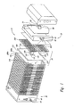
- Figure 1 illustrates a representative electrochemical fuel cell stack 10, including a pair of end plate assemblies 20 and 30, and a plurality of stacked fuel cells 50, each comprising an MEA 100, and a pair of separator plates 200. Between each adjacent pair of MEAs 100 in the stack, there are two separator plates 200 which have adjoining surfaces. An adjoining pair of separator plates are shown as 200a and 200b.
- a tension member 60 extends between end plate assemblies 20 and 30 to retain and secure stack 10 in its assembled state.
- Spring 70 with clamping members 80 grip an end of tension member 60 to apply a compressive force to fuel cells 50 of stack 10.
- Fluid reactant streams are supplied to and exhausted from internal manifolds and passages in stack 10 via inlet and outlet ports 40 in end plate assemblies 20 and 30.
- reactant manifold openings may instead be positioned to form edge or external reactant manifolds.
- perimeter seal 110 is provided around the outer edge of both sides of MEA 100.
- Manifold seals 120 circumscribe internal reactant manifold openings 105 on both sides of MEA 100.
- seals 110 and 120 cooperate with the adjacent pair of plates 200 to fluidly isolate fuel and oxidant reactant streams in internal reactant manifolds and passages, thereby isolating one reactant stream from the other and preventing the streams from leaking from stack 10.
- each MEA 100 is positioned between the active surfaces of two separator plates 200.
- Each separator plate 200 has flow field channels 210 (partially shown) on the active surface thereof (which contacts the MEA) for distributing fuel or oxidant fluid streams to the active area of the contacted electrode of the MEA 100.
- flow field channels 210 on the active surface of plates 200 are fluidly connected to internal reactant manifold openings 205 in plate 200 via supply/exhaust passageways comprising backfeed channels 220 (partially shown) located on the non-active surface of separator plate 200 and ports 230 extending through ( i.e., penetrating the thickness) of plate 200.
- One end of port 230 is open to the active area of separator plate 200 and the other end of port 230 is open to backfeed channels 220.
- the electrochemical fuel cell stacks of the present invention comprise a means for minimizing fluid backflow from the anode exhaust manifold into the anode flow field channels of the fuel cells of the fuel cell stack.
- such means for minimizing fluid backflow may comprise a plurality of valves integrated into the fuel cell stack such that a valve is interposed between the anode flow field channels of each fuel cell and the anode exhaust manifold, or a movable member positioned inside of the anode exhaust manifold such that the movable member prevents fluid flow between the anode flow field channels of the fuel cells and the anode exhaust manifold when moved into a blocking position.
- such means for minimizing fluid backflow may comprise a plurality of narrow restriction orifices positioned between the anode flow field channels of each fuel cell and the anode exhaust manifold such that the amount of any backflow would be significantly limited.
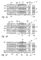
- FIGS 2A-2C are a series of partial cross-sectional views of a representative electrochemical fuel cell stack 10 of the present invention comprising a plurality of flapper-type check valves 300.
- fuel cell stack 10 comprises a plurality of fuel cells 50, each fuel cell 50 comprising an MEA 100 (comprising a solid polymer electrolyte or ion-exchange membrane disposed between two electrodes, namely, a cathode and an anode (not specifically shown)), an anode flow field plate 200a, and a cathode flow field plate 200b.
- Each anode flow field plate 200a comprises at least one anode flow field channel 210a
- each cathode flow field plate 200b comprises at least one cathode flow field channel 210b.
- fuel cell stack 10 comprises an anode exhaust manifold 350 fluidly connected to anode flow field channels 210a via backfeed channels 220, first port 230a and second port 230b in anode flow field plate 200a.
- Anode exhaust manifold 350 may be dead-ended or not dead-ended.
- fuel cell stack 10 further comprises a plurality of seals 115, which cooperate with the adjacent surfaces of anode and cathode flow field plates 200a and 200b to fluidly isolate fuel and oxidant reactant streams in anode and cathode flow fields and reactant manifolds (such as anode exhaust manifold 350) and prevent the streams from leaking from fuel cell stack 10.
- Flapper-type check valves 300 are integrated into fuel cell stack 10 such that a flapper-type check valve 300 is interposed between anode flow field channels 210a of each fuel cell 50 and anode exhaust manifold 350.
- flapper-type check valves 300 may be an extension of (and made from the same material as) seal 115.
- flapper-type check valves 300 may be a polymer film, metallic reed valve, or elastomeric material.
- Figures 2A-2C illustrate the operation of fuel cell stack 10.
- Figure 2A illustrates the position of flapper-type check valves 300 prior to operation of fuel cell stack 10
- Figure 2B illustrates the position of flapper-type check valves 300 during operation of fuel cell stack 10
- Figure 2C illustrates the position of flapper-type check valves 300 during purging of anode flow field channels 210a.
- FIG 2A prior to operation of fuel cell stack 10, there is no fluid flow through anode flow field channels 210a and flapper-type check valves 300 are closed.
- a fuel stream is supplied to anode flow field channels 210a of fuel cells 10 at an operating pressure (e.g., 200-2000 mbar at the inlet to fuel cell stack 10).
- flapper-type check valves 300 This operating pressure is sufficient to open flapper-type check valves 300 and allow fluid flow from anode flow field channels 210a into anode exhaust manifold 350 via backfeed channels 220, first port 230a and second port 230b.
- flapper-type check valves 300 will remain open until the pressure in anode exhaust manifold 350 equilibrates with the pressure in anode flow field channels 210a. Following such equilibration, flapper-type check valves 300 will close until an increase in pressure differential re-opens them ( e.g., as a result of an up-transient or a purge period).
- Anode flow field channels may be purged at regular intervals or in response to one or more monitored operating parameters of fuel cell stack 10 indicative of fuel cell stack performance (e.g., standard deviation of cell voltage, average cell voltage vs. load, or amount of time since previous purge period).
- monitored operating parameters of fuel cell stack 10 indicative of fuel cell stack performance (e.g., standard deviation of cell voltage, average cell voltage vs. load, or amount of time since previous purge period).
- FIGS 3A-3C are a series of partial cross-sectional views of a representative electrochemical fuel cell stack 10 of the present invention comprising a plurality of ball-type check valves 400.
- fuel cell stack 10 comprises a plurality of fuel cells 50, each fuel cell 50 comprising an MEA 100 (comprising a solid polymer electrolyte or ion-exchange membrane disposed between two electrodes, namely, a cathode and an anode (not specifically shown)), an anode flow field plate 200a, and a cathode flow field plate 200b.
- Each anode flow field plate 200a comprises at least one anode flow field channel 210a
- each cathode flow field plate 200b comprises at least one cathode flow field channel 210b.
- fuel cell stack 10 comprises an anode exhaust manifold 350 fluidly connected to anode flow field channels 210a via backfeed channels 220, first port 230a and second port 230b in anode flow field plate 200a.
- Anode exhaust manifold may be dead-ended or not dead-ended.
- fuel cell stack 10 further comprises a plurality of seals 115, which cooperate with the adjacent surfaces of anode and cathode flow field plates 200a and 200b to fluidly isolate fuel and oxidant reactant streams in anode and cathode flow fields and reactant manifolds (such as anode exhaust manifold 350) and prevent the streams from leaking from fuel cell stack 10.
- Ball-type check valves 400 are integrated into fuel cell stack 10 such that a ball-type check valve 400 is interposed between anode flow field channels 210a of each fuel cell 50 and anode exhaust manifold 350. As shown in the illustrated embodiment, ball-type check valves 400 may be actuated against angled surfaces 235 of port 230b by springs 410. In other embodiments, ball-type check valves 400 may be actuated against angled surfaces 235 by gravity.
- Figures 3A-3C illustrate the operation of fuel cell stack 10, which is similar to the operation of fuel cell stack 10 of Figures 2A-2C.
- Figure 3A illustrates the position of ball-type check valves 400 prior to operation of fuel cell stack 10
- Figure 3B illustrates the position of ball-type check valves 400 during operation of fuel cell stack 10
- Figure 3C illustrates the position of ball-type check valves 400 during purging of anode flow field channels 210a.
- FIG. 3A prior to operation of fuel cell stack 10, there is no fluid flow through anode flow field channels 210a and ball-type check valves 400 are closed.
- a fuel stream is supplied to anode flow field channels 210a of fuel cells 10 at an operating pressure (e.g., 200-2000 mbar at the inlet to fuel cell stack 10).
- This operating pressure is sufficient to open ball-type check valves 400 and allow fluid flow from anode flow field channels 210a into anode exhaust manifold 350 via backfeed channels 220, first port 230a and second port 230b.
- ball-type check valves 400 will remain open until the pressure in anode exhaust manifold 350 equilibrates with the pressure in anode flow field channels 210a.
- ball-type check valves 400 will close until an increase in pressure differential re-opens them (e.g., as a result of an up-transient or a purge period).
- a restriction in fluid flow i.e., the flow of the fuel stream through anode flow field channels 210a is not sufficient to prevent fluid backflow from anode exhaust manifold 350
- the corresponding ball-type check valve 400 will close, thereby minimizing any fluid backflow from anode exhaust manifold 350.
- anode flow field channels 210a As shown in Figure 3C, during purging of anode flow field channels 210a, the flow of the fuel stream supplied to anode flow field channels 210a is increased to a purge flow, which is sufficient to remove any accumulated impurities from anode flow field channels 210a and open any closed ball-type check valves 400.
- Anode flow field channels may be purged at regular intervals or in response to one or more monitored operating parameters of fuel cell stack 10 indicative of fuel cell stack performance (e.g., standard deviation of cell voltage, average cell voltage vs. load, or amount of time since previous purge period).
- FIGS 4A-4C are a series of partial cross-sectional views of a representative electrochemical fuel cell stack 10 of the present invention comprising a plurality of plug valves 500.
- fuel cell stack 10 comprises a plurality of fuel cells 50, each fuel cell 50 comprising an MEA 100 (comprising a solid polymer electrolyte or ion-exchange membrane disposed between two electrodes, namely, a cathode and an anode (not specifically shown)), an anode flow field plate 200a, and a cathode flow field plate 200b.
- Each anode flow field plate 200a comprises at least one anode flow field channel 210a
- each cathode flow field plate 200b comprises at least one cathode flow field channel 210b.
- fuel cell stack 10 comprises an anode exhaust manifold 350 fluidly connected to anode flow field channels 210a via backfeed channels 220, first port 230a and second port 230b in anode flow field plate 200a.
- Anode exhaust manifold 350 may be dead-ended or not dead-ended.
- fuel cell stack 10 further comprises a plurality of seals 115, which cooperate with the adjacent surfaces of anode and cathode flow field plates 200a and 200b to fluidly isolate fuel and oxidant reactant streams in anode and cathode flow fields and reactant manifolds (such as anode exhaust manifold 350) and prevent the streams from leaking from fuel cell stack 10.
- Plug valves 500 are integrated into fuel cell stack 10 such that a plug valve 500 is interposed between anode flow field channels 210a of each fuel cell 50 and anode exhaust manifold 350.
- Each plug valve 500 comprises a through-hole 510, which permits fluid flow from anode flow field channels 210a into anode exhaust manifold 350 via backfeed channels 220, first port 230a and second port 230b, when aligned with the openings into second port 230b and anode exhaust manifold 350.
- Plug valves 500 may be actuated individually or may be connected to one another ( e.g., via a common shaft extending through fuel cell stack 10) and be actuated together.
- Figures 4A-4C illustrate one embodiment of the operation of fuel cell stack 10, namely, an embodiment wherein plug valves 500 are actuated together.
- Figure 4A illustrates the position of plug valves 500 prior to operation of fuel cell stack 10
- Figure 4B illustrates the position of plug valves 500 during operation of fuel cell stack 10
- Figure 4C illustrates the position of plug valves 500 during purging of anode flow field channels 210a.
- FIG 4A prior to operation of fuel cell stack 10, all plug valves 500 are open.
- a fuel stream is supplied to anode flow field channels 210a of fuel cells 50 at an operating pressure (e.g., 200-2000 mbar at the inlet to fuel cell stack 10).
- plug valves 500 may be actuated individually such that when a particular fuel cell 50 begins to experience a restriction in fluid flow (i.e., the flow of the fuel stream through anode flow field channels 210a is not sufficient to prevent fluid backflow from anode exhaust manifold 350), the corresponding plug valve 500 may be closed, thereby minimizing any fluid backflow from anode exhaust manifold 350.
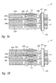
- FIGS 5A and 5B are partial cross-sectional views of a representative electrochemical fuel cell stack 10 of the present invention comprising a movable member 600 positioned inside of the anode exhaust manifold 350.
- fuel cell stack 10 comprises a plurality of fuel cells 50, each fuel cell 50 comprising an MEA 100 (comprising a solid polymer electrolyte or ion-exchange membrane disposed between two electrodes, namely, a cathode and an anode (not specifically shown)), an anode flow field plate 200a, and a cathode flow field plate 200b.
- Each anode flow field plate 200a comprises at least one anode flow field channel 210a
- each cathode flow field plate 200b comprises at least one cathode flow field channel 210b.
- fuel cell stack 10 comprises an anode exhaust manifold 350 fluidly connected to anode flow field channels 210a via backfeed channels 220, first port 230a and second port 230b in anode flow field plate 200a.
- second port 230b may not be present and backfeed channels 200 may be directly connected to anode exhaust manifold 350.
- Anode exhaust manifold 350 may be dead-ended or not dead-ended.
- fuel cell stack 10 further comprises a plurality of seals 115, which cooperate with the adjacent surfaces of anode and cathode flow field plates 200a and 200b to fluidly isolate fuel and oxidant reactant streams in anode and cathode flow fields and reactant manifolds (such as anode exhaust manifold 350) and prevent the streams from leaking from fuel cell stack 10.
- seals 115 which cooperate with the adjacent surfaces of anode and cathode flow field plates 200a and 200b to fluidly isolate fuel and oxidant reactant streams in anode and cathode flow fields and reactant manifolds (such as anode exhaust manifold 350) and prevent the streams from leaking from fuel cell stack 10.
- fuel cell stack 10 further comprises a movable member 600 positioned inside of anode exhaust manifold 350 such that the movable member 600 prevents fluid flow between anode flow field channels 210a and anode exhaust manifold 350 when moved into a blocking position.
- anode exhaust manifold 350 has a circular cross-section and movable member 600 is a hollow rod rotatable within anode exhaust manifold 350 and having an aperture 610 extending along its length such that movable member 600 has a C-shaped cross-section (as shown in Figure 5C) and prevents fluid flow between anode flow field channels 210a of fuel cells 50 and anode exhaust manifold 350 when aperture 610 is not aligned with the openings into port 230b (and, consequently, anode flow field channels 210a).
- Figure 5A illustrates a closed (or blocking) position of movable member 600 (i.e., aperture 610 is not aligned with anode flow field channels 210a) and Figure 5B illustrates an open (or not blocking) position of movable member 600 ( i,e., aperture 610 is aligned with anode flow field channels 210a).
- movable member 600 must be non-conductive and resistant to the anode exhaust environment.
- movable member 600 must ensure sealing between fuel cells 50 and anode exhaust manifold 350 (however, if fuel cell stack 10 comprises a purge valve interposed between anode exhaust manifold 350 and the anode exhaust outlet from fuel cell stack 10, the necessity for this sealing requirement is reduced). In addition, the design of movable member 600 must accommodate for changes in stack length.
- movable member 600 will remain in a closed position except during the limited periods when anode flow field channels 210a are being purged. In this way, no flow (either forward or back) is permitted between anode flow field channels 210a and anode exhaust manifold 350 except during limited purge periods. During such purge periods, moveable member 600 will be rotated into an open position, as shown in Figure 5B.
- anode flow field channels 210a may be purged at regular intervals or in response to one or more monitored operating parameters of fuel cell stack 10 indicative of fuel cell stack performance (e.g., standard deviation of cell voltage, average cell voltage vs. load, or amount of time since previous purge period). Accordingly, moveable member 600 may be continuously rotated or may be rotated only in response to such monitored operating parameters.
- aperture 610 may be wrapped partially around movable member 600 in a helical manner, thereby enabling a staggered purge of fuel cells 50 in fuel cell stack 10. Since aperture 610 is only partially wrapped around movable member 600, it remains possible to position movable member 600 such that all fuel cells 50 are closed off from anode exhaust manifold 350 ( i.e., no fluid flow between anode flow field channels 210a and anode exhaust manifold 350). The resulting staggered purge of this embodiment would produce a more constant and continuous exhaust stream, thereby providing for a more manageable emission stream.
Landscapes
- Life Sciences & Earth Sciences (AREA)
- Engineering & Computer Science (AREA)
- Manufacturing & Machinery (AREA)
- Sustainable Development (AREA)
- Sustainable Energy (AREA)
- Chemical & Material Sciences (AREA)
- Chemical Kinetics & Catalysis (AREA)
- Electrochemistry (AREA)
- General Chemical & Material Sciences (AREA)
- Fuel Cell (AREA)
Abstract
Description
- The present invention relates generally to electrochemical fuel cell stacks, and, more particularly, to an electrochemical fuel cell stack with integrated anode exhaust valves.
- Electrochemical fuel cells convert reactants, namely fuel and oxidant fluid streams, to generate electric power and reaction products. Electrochemical fuel cells generally employ an electrolyte disposed between two electrodes, namely a cathode and an anode. An electrocatalyst, disposed at the interfaces between the electrolyte and the electrodes, typically induces the desired electrochemical reactions at the electrodes. The location of the electrocatalyst generally defines the electrochemically active area.
- One type of electrochemical fuel cell is the polymer electrolyte membrane (PEM) fuel cell. PEM fuel cells generally employ a membrane electrode assembly (MEA) comprising a solid polymer electrolyte or ion-exchange membrane disposed between two electrodes. Each electrode typically comprises a porous, electrically conductive substrate, such as carbon fiber paper or carbon cloth, which provides structural support to the membrane and serves as a fluid diffusion layer. The membrane is ion conductive (typically proton conductive), and acts both as a barrier for isolating the reactant streams from each other and as an electrical insulator between the two electrodes. A typical commercial PEM is a sulfonated perfluorocarbon membrane sold by E.I. Du Pont de Nemours and Company under the trade designation NAFION®. The electrocatalyst is typically a precious metal composition (e.g., platinum metal black or an alloy thereof) and may be provided on a suitable support (e.g., fine platinum particles supported on a carbon black support).
- In a fuel cell, a MEA is typically interposed between two separator plates that are substantially impermeable to the reactant fluid streams. The plates typically act as current collectors and provide support for the MEA. In addition, the plates may have reactant flow field channels formed therein and act as flow field plates providing access for the reactant fluid streams to the respective porous electrodes and providing for the removal of reaction products formed during operation of the fuel cell.
- In a fuel cell stack, a plurality of fuel cells are connected together, typically in series, to increase the overall output power of the assembly. In such an arrangement, one side of a given separator plate may serve as an anode flow field plate for one cell and the other side of the plate may serve as the cathode flow field plate for the adjacent cell. In this arrangement, the plates may be referred to as bipolar plates. Typically, a plurality of inlet ports, supply manifolds, exhaust manifolds and outlet ports are utilized to direct the reactant fluid to the reactant flow field channels in the flow field plates. The supply and exhaust manifolds may be internal manifolds, which extend through aligned openings formed in the flow field plates and MEAs, or may comprise external or edge manifolds, attached to the edges of the flow field plates.
- Certain fuel cell stacks are designed to operate in a closed mode with respect to one or both reactants. Such closed reactant supply systems include dead-ended configurations in which a reactant exhaust manifold is generally closed, as well as systems employing closed-loop recirculation of the reactant exhaust stream from the reactant outlet port to the reactant inlet port and through the fuel cell stack with the addition of fresh reactant.
- A broad range of reactants can be used in PEM fuel cells. For example, the fuel stream may be substantially pure hydrogen gas, a gaseous hydrogen-containing reformate stream, or methanol in a direct methanol fuel cell. The oxidant may be, for example, substantially pure oxygen or a dilute oxygen stream such as air.
- During normal operation of a PEM fuel cell, fuel is electrochemically oxidized on the anode side, typically resulting in the generation of protons, electrons, and possibly other species depending on the fuel employed. The protons are conducted from the reaction sites at which they are generated, through the membrane, to electrochemically react with the oxidant on the cathode side. The electrons travel through an external circuit providing useable power and then react with the protons and oxidant on the cathode side to generate water reaction product.
- During operation of a fuel cell stack, non-reactive components or impurities, such as nitrogen and water, may accumulate within the reactant flow field channels and reactant exhaust manifolds of the fuel cells and fuel cell stack, and adversely affect fuel cell performance. In certain fuel cell stacks, such as closed reactant supply systems, a purge valve (which is normally closed in closed system operation) is provided somewhere in the reactant exhaust manifold for periodic venting of these accumulated impurities. In conventional fuel cell purge systems, the purge valve is opened from time to time, for example, manually or at regular fixed time intervals. Alternatively a purge is triggered, for example, when the voltage or electrical output of one or more cells in a stack falls below a predetermined threshold value (see, for example,
GB Patent No. 1 223 941 US Patent No. 3,553,026 ), or after the fuel cell has expended a preselected number of ampere-hours (see, for example,US Patent No. 3,697,325 ). - Although purging can improve performance of fuel cell stacks, it wastes valuable fuel. Furthermore, the release of hydrogen into the ambient environment may be undesirable. Accordingly, although there have been advances in the field, there remains a need for improved methods of removing, and minimizing the effect on fuel cell performance of, accumulated impurities within reactant flow field channels and reactant exhaust manifolds. The present invention addresses these needs and provides further related advantages.
- In brief, the present invention is directed to an electrochemical fuel cell stack with integrated anode exhaust valves.
- In one embodiment, the present invention provides an electrochemical fuel cell stack comprising a plurality of fuel cells, each fuel cell having an anode and at least one anode flow field channel, an anode exhaust manifold fluidly connected to the at least one anode flow field channel of each fuel cell, and a means for minimizing fluid backflow from the anode exhaust manifold into the anode flow field channels of the fuel cells.
- In a more specific embodiment of the foregoing, the means for minimizing fluid backflow comprises a plurality of valves integrated into the fuel cell stack such that a valve is interposed between the at least one anode flow field channel of each fuel cell and the anode exhaust manifold. For example, the valves may be check valves, such as ball-type check valves or flapper-type check valves, or the valves may be plug valves. In certain embodiments, the plurality of valves prevents fluid backflow from the anode exhaust manifold into the anode flow field channels of the fuel cells.
- In another more specific embodiment, the means for minimizing fluid backflow comprises a movable member positioned inside of the anode exhaust manifold such that the movable member prevents fluid flow between the anode flow field channels of the fuel cells and the anode exhaust manifold when moved into a blocking position. For example, in a representative embodiment, the anode exhaust manifold has a circular cross-section and the movable member comprises a hollow rod rotatable within the anode exhaust manifold, the hollow rod having an aperture extending along its length such that the hollow rod has a C-shaped cross-section and prevents fluid flow between the anode flow field channels of the fuel cells and the anode exhaust manifold when the aperture is not aligned with the anode flow field channels of the fuel cells. In a further embodiment of the foregoing, the aperture may be partially wrapped around the hollow rod in a helical manner.
- In various embodiments of the foregoing electrochemical fuel cell stacks, the plurality of fuel cells may be polymer electrolyte membrane fuel cells and the anode exhaust manifold may be either dead-ended or not dead-ended.
- The present invention is also directed to methods of operating an electrochemical fuel cell stack with integrated anode exhaust valves.
- In one embodiment, a method of purging an electrochemical fuel cell stack comprising a plurality of fuel cells, each fuel cell having an anode and at least one anode flow field channel, an anode exhaust manifold fluidly connected to the at least one anode flow field channel of each fuel cell, and a means for minimizing fluid backflow from the anode exhaust manifold into the anode flow field channels of the fuel cells is disclosed, the method comprising supplying a fuel stream to the anode flow field channels of each fuel cell at an operating pressure, and periodically purging the anode flow field channels of each fuel cell by increasing the flow of the fuel stream to a purge flow, wherein the purge flow is sufficient to remove any accumulated impurities from the anode flow field channels.
- In a second embodiment, a method of reducing fuel cell voltage variation in an electrochemical fuel cell stack comprising a plurality of fuel cells, each fuel cell having an anode and at least one anode flow field channel, an anode exhaust manifold fluidly connected to the at least one anode flow field channel of each fuel cell, and a means for minimizing fluid backflow from the anode exhaust manifold into the anode flow field channels of the fuel cells is disclosed, the method comprising supplying a fuel stream to the anode flow field channels of each fuel cell at an operating pressure, and periodically purging the anode flow field channels of each fuel cell by increasing the flow of the fuel stream to a purge flow, wherein the purge flow is sufficient to remove any accumulated impurities from the anode flow field channels.
- In various embodiments of the foregoing methods, the anode flow field channels may be purged at regular intervals or in response to one or more monitored operating parameters of the fuel cell stack indicative of fuel cell performance.
- In more specific embodiments, the means for minimizing fluid backflow from the anode exhaust manifold into the anode flow field channels of the fuel cells comprises a plurality of check valves integrated into the fuel cell stack such that a check valve is interposed between the at least one anode flow field channel of each fuel cell and the anode exhaust manifold, and the purge flow is sufficient to open any closed check valves. In certain embodiments, the plurality of check valves prevent fluid backflow from the anode exhaust manifold into the anode flow field channels of the fuel cells.
- In other more specific embodiments, the means for minimizing fluid backflow from the anode exhaust manifold into the anode flow field channels of the fuel cells comprises a plurality of plug valves integrated into the fuel cell stack such that a plug valve is interposed between the at least one anode flow field channel of each fuel cell and the anode exhaust manifold, and the plug valves are opened during purging of the anode flow field channels. In certain embodiments, the plurality of plug valves prevent fluid backflow from the anode exhaust manifold into the anode flow field channels of the fuel cells.
- In yet other more specific embodiments, the means for minimizing fluid backflow comprises a movable member positioned inside of the anode exhaust manifold such that the movable member prevents fluid flow between the anode flow field channels of the fuel cells and the anode exhaust manifold when moved into a blocking position, and wherein the movable member is not in a blocking position during purging of the anode flow field channels.
- These and other aspects of the invention will be evident upon reference to the following detailed description and attached drawings.
- In the drawings, identical reference numbers identify similar elements or acts. The sizes and relative positions of elements in the drawings are not necessarily drawn to scale. For example, the shapes of various elements and angles are not drawn to scale, and some of these elements are arbitrarily enlarged and positioned to improve drawing legibility. Further, the particular shapes of the elements as drawn, are not intended to convey any information regarding the actual shape of the particular elements, and have been solely selected for ease of recognition in the drawings.
- Figure 1
- is a partially exploded perspective view of a representative electrochemical fuel cell stack.
- Figures 2A-2C
- are a series of partial cross-sectional views of a representative electrochemical fuel cell stack of the present invention comprising a plurality of flapper-type check valves.
- Figures 3A-3C
- are a series of partial cross-sectional views of a representative electrochemical fuel cell stack of the present invention comprising a plurality of ball-type check valves.
- Figures 4A-4C
- are a series of partial cross-sectional views of a representative electrochemical fuel cell stack of the present invention comprising a plurality of plug valves.
- Figures 5A and 5B
- are partial cross-sectional views of a representative electrochemical fuel cell stack of the present invention comprising a movable member positioned inside of the anode exhaust manifold.
- Figure 5C
- is a top view of the anode exhaust manifold of a representative electrochemical fuel cell stack of the present invention comprising a movable member positioned inside of the anode exhaust manifold.
- In the following description, certain specific details are set forth in order to provide a thorough understanding of various embodiments of the invention. However, one skilled in the art will understand that the invention may be practiced without these details. In other instances, well-known structures associated with fuel cells, fuel cell stacks, and fuel cell systems have not been shown or described in detail to avoid unnecessarily obscuring descriptions of the embodiments of the invention.
- Unless the context requires otherwise, throughout the specification and claims which follow, the word "comprise" and variations thereof, such as, "comprises" and "comprising" are to be construed in an open, inclusive sense, that is as "including, but not limited to".
- Reference throughout this specification to "one embodiment" or "an embodiment" means that a particular feature, structure or characteristic described in connection with the embodiment is included in at least one embodiment of the present invention. Thus, the appearances of the phrases "in one embodiment" or "in an embodiment" in various places throughout this specification are not necessarily all referring to the same embodiment. Furthermore, the particular features, structures, or characteristics may be combined in any suitable manner in one or more embodiments.
- As described above, during operation of a fuel cell stack, non-reactive components or impurities, such as nitrogen and water, may accumulate within the reactant flow field channels and reactant exhaust manifolds of the fuel cells and fuel cell stack, and adversely affect fuel cell performance. For example, within a given fuel cell stack, such impurities may tend to accumulate in certain fuel cells due to the formation of stagnation areas within the flow field channels of such fuel cells.
- During normal operation, the fluid pressure drop across each fuel cell (i.e., the difference in fluid pressure between the inlet and outlet of the fuel cell) is relatively low (e.g., about 40 mbar/slpm) and the flow of the reactant streams through the fuel cells is sufficient to prevent fluid backflow from the reactant exhaust manifold into the reactant flow field channels. However, as a result of, for example, manufacturing tolerances, water accumulation, and temperature changes, the flow of the reactant streams through the reactant flow field channels of certain fuel cells may be restricted (i.e., decrease) during operation. In such fuel cells, the reduced flow of the reactant stream through the fuel cells is no longer sufficient to prevent fluid backflow from the reactant exhaust manifold. As a result, stagnation areas will form within the flow field channels of such fuel cells due to the fluid backflow from the reactant exhaust manifold. For a given fuel cell, the location of this stagnation area will depend upon the flow restriction for the fuel cell relative to the average fuel cell stack flow restriction (e.g., a greater flow restriction will result in the formation of a stagnation area closer to the inlet of the affected fuel cell).
- When purging a fuel cell stack, a sufficient amount of reactant must be utilized to ensure that all stagnation areas are cleared. As one of ordinary skill in the art will appreciate, as the stagnation areas move further towards the inlet of the fuel cells, a greater amount of reactant must be purged to ensure complete removal. However, increasing the amount of reactant utilized during purge periods wastes valuable reactants.
- Accordingly, in order to reduce the amount of reactant required to effectively purge a fuel cell stack, in particular, the amount of fuel required, the present invention provides a fuel cell stack comprising a means for minimizing fluid backflow from the anode exhaust manifold into the anode flow field channels of the fuel cells of the fuel cell stack. By minimizing the amount of fluid backflow, any stagnation areas will form near the outlets of the fuel cells. Consequently, less fuel will be required to clear such areas during purge periods. Furthermore, the effective electrochemically active areas of the fuel cells will remain more constant, thereby reducing the fuel cell voltage variation within the fuel cell stack and minimizing the possibility of fuel starvation caused cathode corrosion. In other words, since all stagnation areas will tend to form near the outlet of the fuel cells, the affected fuel cells will have similar reductions in effective active area with respect to time, as well as similar reductions in individual fuel cell voltages with respect to time.
- Figure 1 illustrates a representative electrochemical
fuel cell stack 10, including a pair ofend plate assemblies fuel cells 50, each comprising anMEA 100, and a pair ofseparator plates 200. Between each adjacent pair ofMEAs 100 in the stack, there are twoseparator plates 200 which have adjoining surfaces. An adjoining pair of separator plates are shown as 200a and 200b. Atension member 60 extends betweenend plate assemblies secure stack 10 in its assembled state.Spring 70 with clampingmembers 80 grip an end oftension member 60 to apply a compressive force tofuel cells 50 ofstack 10. - Fluid reactant streams are supplied to and exhausted from internal manifolds and passages in
stack 10 via inlet andoutlet ports 40 inend plate assemblies reactant manifold openings MEAs 100 andseparator plates 200, respectively, form internal reactant manifolds extending throughstack 10. As one of ordinary skill in the art will appreciate, in other representative electrochemical fuel cell stacks, reactant manifold openings may instead be positioned to form edge or external reactant manifolds. - In the illustrated embodiment,
perimeter seal 110 is provided around the outer edge of both sides ofMEA 100. Manifold seals 120 circumscribe internalreactant manifold openings 105 on both sides ofMEA 100. Whenstack 10 is secured in its assembled, compressed state, seals 110 and 120 cooperate with the adjacent pair ofplates 200 to fluidly isolate fuel and oxidant reactant streams in internal reactant manifolds and passages, thereby isolating one reactant stream from the other and preventing the streams from leaking fromstack 10. - As illustrated in Figure 1, each
MEA 100 is positioned between the active surfaces of twoseparator plates 200. Eachseparator plate 200 has flow field channels 210 (partially shown) on the active surface thereof (which contacts the MEA) for distributing fuel or oxidant fluid streams to the active area of the contacted electrode of theMEA 100. In the embodiment illustrated in Figure 1, flowfield channels 210 on the active surface ofplates 200 are fluidly connected to internalreactant manifold openings 205 inplate 200 via supply/exhaust passageways comprising backfeed channels 220 (partially shown) located on the non-active surface ofseparator plate 200 andports 230 extending through (i.e., penetrating the thickness) ofplate 200. One end ofport 230 is open to the active area ofseparator plate 200 and the other end ofport 230 is open to backfeedchannels 220. - As noted above, the electrochemical fuel cell stacks of the present invention comprise a means for minimizing fluid backflow from the anode exhaust manifold into the anode flow field channels of the fuel cells of the fuel cell stack. As illustrated in the following Figures, in various embodiments, such means for minimizing fluid backflow may comprise a plurality of valves integrated into the fuel cell stack such that a valve is interposed between the anode flow field channels of each fuel cell and the anode exhaust manifold, or a movable member positioned inside of the anode exhaust manifold such that the movable member prevents fluid flow between the anode flow field channels of the fuel cells and the anode exhaust manifold when moved into a blocking position. In addition, in alternate embodiments (not illustrated), such means for minimizing fluid backflow may comprise a plurality of narrow restriction orifices positioned between the anode flow field channels of each fuel cell and the anode exhaust manifold such that the amount of any backflow would be significantly limited.
- Figures 2A-2C are a series of partial cross-sectional views of a representative electrochemical
fuel cell stack 10 of the present invention comprising a plurality of flapper-type check valves 300. As illustrated,fuel cell stack 10 comprises a plurality offuel cells 50, eachfuel cell 50 comprising an MEA 100 (comprising a solid polymer electrolyte or ion-exchange membrane disposed between two electrodes, namely, a cathode and an anode (not specifically shown)), an anodeflow field plate 200a, and a cathodeflow field plate 200b. Each anodeflow field plate 200a comprises at least one anodeflow field channel 210a, and each cathodeflow field plate 200b comprises at least one cathodeflow field channel 210b. - As further illustrated in Figures 2A-2C,
fuel cell stack 10 comprises ananode exhaust manifold 350 fluidly connected to anodeflow field channels 210a viabackfeed channels 220,first port 230a andsecond port 230b in anodeflow field plate 200a.Anode exhaust manifold 350 may be dead-ended or not dead-ended. In addition,fuel cell stack 10 further comprises a plurality ofseals 115, which cooperate with the adjacent surfaces of anode and cathodeflow field plates fuel cell stack 10. - Flapper-
type check valves 300 are integrated intofuel cell stack 10 such that a flapper-type check valve 300 is interposed between anodeflow field channels 210a of eachfuel cell 50 andanode exhaust manifold 350. For example, as shown in the illustrated embodiment, flapper-type check valves 300 may be an extension of (and made from the same material as)seal 115. Alternatively, flapper-type check valves 300 may be a polymer film, metallic reed valve, or elastomeric material. - When viewed in series, Figures 2A-2C illustrate the operation of
fuel cell stack 10. Figure 2A illustrates the position of flapper-type check valves 300 prior to operation offuel cell stack 10, Figure 2B illustrates the position of flapper-type check valves 300 during operation offuel cell stack 10, and Figure 2C illustrates the position of flapper-type check valves 300 during purging of anodeflow field channels 210a. As shown in Figure 2A, prior to operation offuel cell stack 10, there is no fluid flow through anodeflow field channels 210a and flapper-type check valves 300 are closed. During operation, a fuel stream is supplied to anodeflow field channels 210a offuel cells 10 at an operating pressure (e.g., 200-2000 mbar at the inlet to fuel cell stack 10). This operating pressure is sufficient to open flapper-type check valves 300 and allow fluid flow from anodeflow field channels 210a intoanode exhaust manifold 350 viabackfeed channels 220,first port 230a andsecond port 230b. In embodiments whereinanode exhaust manifold 350 is dead-ended, flapper-type check valves 300 will remain open until the pressure inanode exhaust manifold 350 equilibrates with the pressure in anodeflow field channels 210a. Following such equilibration, flapper-type check valves 300 will close until an increase in pressure differential re-opens them (e.g., as a result of an up-transient or a purge period). As shown in Figure 2B, when a particular fuel cell 50 (illustrated by the center fuel cell in Figure 2B) begins to experience a restriction in fluid flow (i.e., the flow of the fuel stream through anodeflow field channels 210a is not sufficient to prevent fluid backflow from anode exhaust manifold 350), the corresponding flapper-type check valve 300 will close, thereby minimizing any fluid backflow fromanode exhaust manifold 350. As shown in Figure 2C, during purging of anodeflow field channels 210a, the flow of the fuel stream supplied to anodeflow field channels 210a is increased to a purge flow, which is sufficient to remove any accumulated impurities from anodeflow field channels 210a and open any closed flapper-type check valves 300. Anode flow field channels may be purged at regular intervals or in response to one or more monitored operating parameters offuel cell stack 10 indicative of fuel cell stack performance (e.g., standard deviation of cell voltage, average cell voltage vs. load, or amount of time since previous purge period). - Figures 3A-3C are a series of partial cross-sectional views of a representative electrochemical
fuel cell stack 10 of the present invention comprising a plurality of ball-type check valves 400. As in Figures 2A-2C,fuel cell stack 10 comprises a plurality offuel cells 50, eachfuel cell 50 comprising an MEA 100 (comprising a solid polymer electrolyte or ion-exchange membrane disposed between two electrodes, namely, a cathode and an anode (not specifically shown)), an anodeflow field plate 200a, and a cathodeflow field plate 200b. Each anodeflow field plate 200a comprises at least one anodeflow field channel 210a, and each cathodeflow field plate 200b comprises at least one cathodeflow field channel 210b. - Also similar to Figures 2A-2C,
fuel cell stack 10 comprises ananode exhaust manifold 350 fluidly connected to anodeflow field channels 210a viabackfeed channels 220,first port 230a andsecond port 230b in anodeflow field plate 200a. Anode exhaust manifold may be dead-ended or not dead-ended. In addition,fuel cell stack 10 further comprises a plurality ofseals 115, which cooperate with the adjacent surfaces of anode and cathodeflow field plates fuel cell stack 10. - Ball-
type check valves 400 are integrated intofuel cell stack 10 such that a ball-type check valve 400 is interposed between anodeflow field channels 210a of eachfuel cell 50 andanode exhaust manifold 350. As shown in the illustrated embodiment, ball-type check valves 400 may be actuated againstangled surfaces 235 ofport 230b bysprings 410. In other embodiments, ball-type check valves 400 may be actuated againstangled surfaces 235 by gravity. - When viewed in series, Figures 3A-3C illustrate the operation of
fuel cell stack 10, which is similar to the operation offuel cell stack 10 of Figures 2A-2C. Figure 3A illustrates the position of ball-type check valves 400 prior to operation offuel cell stack 10, Figure 3B illustrates the position of ball-type check valves 400 during operation offuel cell stack 10, and Figure 3C illustrates the position of ball-type check valves 400 during purging of anodeflow field channels 210a. As shown in Figure 3A, prior to operation offuel cell stack 10, there is no fluid flow through anodeflow field channels 210a and ball-type check valves 400 are closed. During operation, a fuel stream is supplied to anodeflow field channels 210a offuel cells 10 at an operating pressure (e.g., 200-2000 mbar at the inlet to fuel cell stack 10). This operating pressure is sufficient to open ball-type check valves 400 and allow fluid flow from anodeflow field channels 210a intoanode exhaust manifold 350 viabackfeed channels 220,first port 230a andsecond port 230b. As with the fuel cell stack of Figures 2A-2C, in embodiments whereinanode exhaust manifold 350 is dead-ended, ball-type check valves 400 will remain open until the pressure inanode exhaust manifold 350 equilibrates with the pressure in anodeflow field channels 210a. Following such equilibration, ball-type check valves 400 will close until an increase in pressure differential re-opens them (e.g., as a result of an up-transient or a purge period). As shown in Figure 3B, when a particular fuel cell 50 (illustrated by the center fuel cell in Figure 3B) begins to experience a restriction in fluid flow (i.e., the flow of the fuel stream through anodeflow field channels 210a is not sufficient to prevent fluid backflow from anode exhaust manifold 350), the corresponding ball-type check valve 400 will close, thereby minimizing any fluid backflow fromanode exhaust manifold 350. As shown in Figure 3C, during purging of anodeflow field channels 210a, the flow of the fuel stream supplied to anodeflow field channels 210a is increased to a purge flow, which is sufficient to remove any accumulated impurities from anodeflow field channels 210a and open any closed ball-type check valves 400. Anode flow field channels may be purged at regular intervals or in response to one or more monitored operating parameters offuel cell stack 10 indicative of fuel cell stack performance (e.g., standard deviation of cell voltage, average cell voltage vs. load, or amount of time since previous purge period). - Figures 4A-4C are a series of partial cross-sectional views of a representative electrochemical
fuel cell stack 10 of the present invention comprising a plurality ofplug valves 500. As illustrated,fuel cell stack 10 comprises a plurality offuel cells 50, eachfuel cell 50 comprising an MEA 100 (comprising a solid polymer electrolyte or ion-exchange membrane disposed between two electrodes, namely, a cathode and an anode (not specifically shown)), an anodeflow field plate 200a, and a cathodeflow field plate 200b. Each anodeflow field plate 200a comprises at least one anodeflow field channel 210a, and each cathodeflow field plate 200b comprises at least one cathodeflow field channel 210b. - As further illustrated,
fuel cell stack 10 comprises ananode exhaust manifold 350 fluidly connected to anodeflow field channels 210a viabackfeed channels 220,first port 230a andsecond port 230b in anodeflow field plate 200a.Anode exhaust manifold 350 may be dead-ended or not dead-ended. In addition,fuel cell stack 10 further comprises a plurality ofseals 115, which cooperate with the adjacent surfaces of anode and cathodeflow field plates fuel cell stack 10. - Plug
valves 500 are integrated intofuel cell stack 10 such that aplug valve 500 is interposed between anodeflow field channels 210a of eachfuel cell 50 andanode exhaust manifold 350. Eachplug valve 500 comprises a through-hole 510, which permits fluid flow from anodeflow field channels 210a intoanode exhaust manifold 350 viabackfeed channels 220,first port 230a andsecond port 230b, when aligned with the openings intosecond port 230b andanode exhaust manifold 350. Plugvalves 500 may be actuated individually or may be connected to one another (e.g., via a common shaft extending through fuel cell stack 10) and be actuated together. - When viewed in series, Figures 4A-4C illustrate one embodiment of the operation of
fuel cell stack 10, namely, an embodiment wherein plugvalves 500 are actuated together. Figure 4A illustrates the position ofplug valves 500 prior to operation offuel cell stack 10, Figure 4B illustrates the position ofplug valves 500 during operation offuel cell stack 10, and Figure 4C illustrates the position ofplug valves 500 during purging of anodeflow field channels 210a. As shown in Figure 4A, prior to operation offuel cell stack 10, all plugvalves 500 are open. During operation, a fuel stream is supplied to anodeflow field channels 210a offuel cells 50 at an operating pressure (e.g., 200-2000 mbar at the inlet to fuel cell stack 10). As shown in Figure 4B, all plugvalves 500 are closed during normal operation and are opened, as shown in Figure 4C, only during the limited periods when anodeflow field channels 210a are being purged. As described previously, during purging of anodeflow field channels 210a, the flow of the fuel stream supplied to anodeflow field channels 210a is increased to a purge flow, which is sufficient to remove any accumulated impurities from anodeflow field channels 210a. Anode flow field channels may be purged at regular intervals or in response to one or more monitored operating parameters offuel cell stack 10 indicative of fuel cell stack performance (e.g., standard deviation of cell voltage, average cell voltage vs. load, or amount of time since previous purge period). In alternate embodiments, plugvalves 500 may be actuated individually such that when aparticular fuel cell 50 begins to experience a restriction in fluid flow (i.e., the flow of the fuel stream through anodeflow field channels 210a is not sufficient to prevent fluid backflow from anode exhaust manifold 350), thecorresponding plug valve 500 may be closed, thereby minimizing any fluid backflow fromanode exhaust manifold 350. - Figures 5A and 5B are partial cross-sectional views of a representative electrochemical
fuel cell stack 10 of the present invention comprising amovable member 600 positioned inside of theanode exhaust manifold 350. As illustrated,fuel cell stack 10 comprises a plurality offuel cells 50, eachfuel cell 50 comprising an MEA 100 (comprising a solid polymer electrolyte or ion-exchange membrane disposed between two electrodes, namely, a cathode and an anode (not specifically shown)), an anodeflow field plate 200a, and a cathodeflow field plate 200b. Each anodeflow field plate 200a comprises at least one anodeflow field channel 210a, and each cathodeflow field plate 200b comprises at least one cathodeflow field channel 210b. - As further illustrated in Figures 5A and 5B,
fuel cell stack 10 comprises ananode exhaust manifold 350 fluidly connected to anodeflow field channels 210a viabackfeed channels 220,first port 230a andsecond port 230b in anodeflow field plate 200a. However, in alternate embodiments,second port 230b may not be present andbackfeed channels 200 may be directly connected toanode exhaust manifold 350.Anode exhaust manifold 350 may be dead-ended or not dead-ended. In addition,fuel cell stack 10 further comprises a plurality ofseals 115, which cooperate with the adjacent surfaces of anode and cathodeflow field plates fuel cell stack 10. - As illustrated,
fuel cell stack 10 further comprises amovable member 600 positioned inside ofanode exhaust manifold 350 such that themovable member 600 prevents fluid flow between anodeflow field channels 210a andanode exhaust manifold 350 when moved into a blocking position. More specifically, in the illustrated embodiment,anode exhaust manifold 350 has a circular cross-section andmovable member 600 is a hollow rod rotatable withinanode exhaust manifold 350 and having anaperture 610 extending along its length such thatmovable member 600 has a C-shaped cross-section (as shown in Figure 5C) and prevents fluid flow between anodeflow field channels 210a offuel cells 50 andanode exhaust manifold 350 whenaperture 610 is not aligned with the openings intoport 230b (and, consequently, anodeflow field channels 210a). For example, Figure 5A illustrates a closed (or blocking) position of movable member 600 (i.e.,aperture 610 is not aligned with anodeflow field channels 210a) and Figure 5B illustrates an open (or not blocking) position of movable member 600 (i,e.,aperture 610 is aligned with anodeflow field channels 210a). As one of skill in the art will appreciate,movable member 600 must be non-conductive and resistant to the anode exhaust environment. Although complete sealing betweenfuel cells 50 is not required,movable member 600 must ensure sealing betweenfuel cells 50 and anode exhaust manifold 350 (however, iffuel cell stack 10 comprises a purge valve interposed betweenanode exhaust manifold 350 and the anode exhaust outlet fromfuel cell stack 10, the necessity for this sealing requirement is reduced). In addition, the design ofmovable member 600 must accommodate for changes in stack length. - As shown in Figure 5A, during normal operation of
fuel cell stack 10,movable member 600 will remain in a closed position except during the limited periods when anodeflow field channels 210a are being purged. In this way, no flow (either forward or back) is permitted between anodeflow field channels 210a andanode exhaust manifold 350 except during limited purge periods. During such purge periods,moveable member 600 will be rotated into an open position, as shown in Figure 5B. As noted with respect to the previously described embodiments, anodeflow field channels 210a may be purged at regular intervals or in response to one or more monitored operating parameters offuel cell stack 10 indicative of fuel cell stack performance (e.g., standard deviation of cell voltage, average cell voltage vs. load, or amount of time since previous purge period). Accordingly,moveable member 600 may be continuously rotated or may be rotated only in response to such monitored operating parameters. - Furthermore, in a further embodiment,
aperture 610 may be wrapped partially aroundmovable member 600 in a helical manner, thereby enabling a staggered purge offuel cells 50 infuel cell stack 10. Sinceaperture 610 is only partially wrapped aroundmovable member 600, it remains possible to positionmovable member 600 such that allfuel cells 50 are closed off from anode exhaust manifold 350 (i.e., no fluid flow between anodeflow field channels 210a and anode exhaust manifold 350). The resulting staggered purge of this embodiment would produce a more constant and continuous exhaust stream, thereby providing for a more manageable emission stream. - While particular steps, elements, embodiments and applications of the present invention have been shown and described herein for purposes of illustration, it will be understood, of course, that the invention is not limited thereto since modifications may be made by persons skilled in the art, particularly in light of the foregoing teachings, without deviating from the spirit and scope of the invention. Accordingly, the invention is not limited except as by the appended claims.
Claims (29)
- An electrochemical fuel cell stack comprising:a plurality of fuel cells, each fuel cell having an anode and at least one anode flow field channel;an anode exhaust manifold fluidly connected to the at least one anode flow field channel of each fuel cell; anda means for minimizing fluid backflow from the anode exhaust manifold into the anode flow field channels of the fuel cells.
- The electrochemical fuel cell stack of claim 1 wherein the means for minimizing fluid backflow comprises a plurality of valves integrated into the fuel cell stack such that a valve is interposed between the at least one anode flow field channel of each fuel cell and the anode exhaust manifold.
- The electrochemical fuel cell stack of claim 2 wherein the plurality of valves prevents fluid backflow from the anode exhaust manifold into the anode flow field channels of the fuel cells.
- The electrochemical fuel cell stack of claim 2 wherein the valves are check valves.
- The electrochemical fuel cell stack of claim 4 wherein the check valves are ball-type check valves.
- The electrochemical fuel cell stack of claim 4 wherein the check valves are flapper-type check valves.
- The electrochemical fuel cell stack of claim 2 wherein the valves are plug valves.
- The electrochemical fuel cell stack of claim 1 wherein the means for minimizing fluid backflow comprises a movable member positioned inside of the anode exhaust manifold such that the movable member prevents fluid flow between the anode flow field channels of the fuel cells and the anode exhaust manifold when moved into a blocking position.
- The electrochemical fuel cell stack of claim 8 wherein the anode exhaust manifold has a circular cross-section and the movable member comprises a hollow rod rotatable within the anode exhaust manifold, the hollow rod having an aperture extending along its length such that the hollow rod has a C-shaped cross-section and prevents fluid flow between the anode flow field channels of the fuel cells and the anode exhaust manifold when the aperture is not aligned with the anode flow field channels of the fuel cells.
- The electrochemical fuel cell stack of claim 9 wherein the aperture wraps partially around the hollow rod in a helical manner.
- The electrochemical fuel cell stack of claim 1 wherein the plurality of fuel cells are polymer electrolyte membrane fuel cells.
- The electrochemical fuel cell stack of claim 1 wherein the anode exhaust manifold is dead-ended.
- The electrochemical fuel cell stack of claim 1 wherein the anode exhaust manifold is not dead-ended.
- A method of purging an electrochemical fuel cell stack comprising a plurality of fuel cells, each fuel cell having an anode and at least one anode flow field channel, an anode exhaust manifold fluidly connected to the at least one anode flow field channel of each fuel cell, and a means for minimizing fluid backflow from the anode exhaust manifold into the anode flow field channels of the fuel cells, the method comprising:supplying a fuel stream to the anode flow field channels of each fuel cell at an operating pressure; andperiodically purging the anode flow field channels of each fuel cell by increasing the flow of the fuel stream to a purge flow,wherein the purge flow is sufficient to remove any accumulated impurities from the anode flow field channels.
- The method of claim 14 wherein the anode flow field channels are purged at regular intervals.
- The method of claim 14 wherein the anode flow field channels are purged in response to one or more monitored operating parameters of the fuel cell stack indicative of fuel cell performance.
- The method of claim 14 wherein the means for minimizing fluid backflow from the anode exhaust manifold into the anode flow field channels of the fuel cells comprises a plurality of check valves integrated into the fuel cell stack such that a check valve is interposed between the at least one anode flow field channel of each fuel cell and the anode exhaust manifold, and wherein the purge flow is sufficient to open any closed check valves.
- The method of claim 17 wherein the plurality of check valves prevents fluid backflow from the anode exhaust manifold into the anode flow field channels of the fuel cells.
- The method of claim 14 wherein the means for minimizing fluid backflow from the anode exhaust manifold into the anode flow field channels of the fuel cells comprises a plurality of plug valves integrated into the fuel cell stack such that a plug valve is interposed between the at least one anode flow field channel of each fuel cell and the anode exhaust manifold, and wherein the plug valves are opened during purging of the anode flow field channels.
- The method of claim 19 wherein the plurality of plug valves prevents fluid backflow from the anode exhaust manifold into the anode flow field channels of the fuel cells.
- The method of claim 14 wherein the means for minimizing fluid backflow comprises a movable member positioned inside of the anode exhaust manifold such that the movable member prevents fluid flow between the anode flow field channels of the fuel cells and the anode exhaust manifold when moved into a blocking position, and wherein the movable member is not in a blocking position during purging of the anode flow field channels.
- A method of reducing fuel cell voltage variation in an electrochemical fuel cell stack comprising a plurality of fuel cells, each fuel cell having an anode and at least one anode flow field channel, an anode exhaust manifold fluidly connected to the at least one anode flow field channel of each fuel cell, and a means for minimizing fluid backflow from the anode exhaust manifold into the anode flow field channels of the fuel cells, the method comprising:supplying a fuel stream to the anode flow field channels of each fuel cell at an operating pressure; andperiodically purging the anode flow field channels of each fuel cell by increasing the flow of the fuel stream to a purge flow,wherein the purge flow is sufficient to remove any accumulated impurities from the anode flow field channels.
- The method of claim 22 wherein the anode flow field channels are purged at regular intervals.
- The method of claim 22 wherein the anode flow field channels are purged in response to one or more monitored operating parameters of the fuel cell stack indicative of fuel cell performance.
- The method of claim 22 wherein the means for minimizing fluid backflow from the anode exhaust manifold into the anode flow field channels of the fuel cells comprises a plurality of check valves integrated into the fuel cell stack such that a check valve is interposed between the at least one anode flow field channel of each fuel cell and the anode exhaust manifold, and wherein the purge flow is sufficient to open any closed check valves.
- The method of claim 25 wherein the plurality of check valves prevents fluid backflow from the anode exhaust manifold into the anode flow field channels of the fuel cells.
- The method of claim 22 wherein the means for minimizing fluid backflow from the anode exhaust manifold into the anode flow field channels of the fuel cells comprises a plurality of plug valves integrated into the fuel cell stack such that a plug valve is interposed between the at least one anode flow field channel of each fuel cell and the anode exhaust manifold, and wherein the plug valves are opened during purging of the anode flow field channels.
- The method of claim 27 wherein the plurality of plug valves prevents fluid backflow from the anode exhaust manifold into the anode flow field channels of the fuel cells.
- The method of claim 22 wherein the means for minimizing fluid backflow comprises a movable member positioned inside of the anode exhaust manifold such that the movable member prevents fluid flow between the anode flow field channels of the fuel cells and the anode exhaust manifold when moved into a blocking position, and wherein the movable member is not in a blocking position during purging of the anode flow field channels.
Applications Claiming Priority (1)
| Application Number | Priority Date | Filing Date | Title |
|---|---|---|---|
| US11/145,553 US8206869B2 (en) | 2005-06-03 | 2005-06-03 | Electrochemical fuel cell stack with integrated anode exhaust valves |
Publications (2)
| Publication Number | Publication Date |
|---|---|
| EP1744390A1 true EP1744390A1 (en) | 2007-01-17 |
| EP1744390B1 EP1744390B1 (en) | 2009-09-09 |
Family
ID=37450976
Family Applications (1)
| Application Number | Title | Priority Date | Filing Date |
|---|---|---|---|
| EP06011372A Not-in-force EP1744390B1 (en) | 2005-06-03 | 2006-06-01 | Electrochemical fuel cell stack with integrated anode exhaust valves |
Country Status (5)
| Country | Link |
|---|---|
| US (1) | US8206869B2 (en) |
| EP (1) | EP1744390B1 (en) |
| AT (1) | ATE442680T1 (en) |
| CA (1) | CA2548708A1 (en) |
| DE (1) | DE602006009026D1 (en) |
Cited By (1)
| Publication number | Priority date | Publication date | Assignee | Title |
|---|---|---|---|---|
| WO2007077037A1 (en) * | 2006-01-06 | 2007-07-12 | Fraunhofer-Gesellschaft zur Förderung der angewandten Forschung e.V. | Microfuel cell system having passive input and output valves and rinsing process |
Families Citing this family (22)
| Publication number | Priority date | Publication date | Assignee | Title |
|---|---|---|---|---|
| US8062797B2 (en) * | 2004-05-07 | 2011-11-22 | Ardica Technologies, Inc. | Articles of clothing and personal gear with on-demand power supply for electrical devices |
| US8187758B2 (en) * | 2005-08-11 | 2012-05-29 | Ardica Technologies Inc. | Fuel cell apparatus with a split pump |
| US20070036711A1 (en) * | 2005-08-11 | 2007-02-15 | Ardica Technologies Inc. | Hydrogen generator |
| US8795926B2 (en) | 2005-08-11 | 2014-08-05 | Intelligent Energy Limited | Pump assembly for a fuel cell system |
| US7858253B2 (en) * | 2005-11-16 | 2010-12-28 | Ford Global Technologies | Time-based fuel cell purge method |
| EP2111667A2 (en) * | 2007-01-04 | 2009-10-28 | Ird Fuel Cells A/S | Modified fuel cell manifolds for controlling fuel gas flow to different sections of fuel cell stacks |
| US7851105B2 (en) * | 2007-06-18 | 2010-12-14 | Daimler Ag | Electrochemical fuel cell stack having staggered fuel and oxidant plenums |
| MX2010001991A (en) | 2007-08-20 | 2010-05-27 | Myfc Ab | Fuel cell assembly having feed-back sensor. |
| CN101971402A (en) * | 2008-01-29 | 2011-02-09 | 阿尔迪卡技术公司 | System for removing non-fuel materials from fuel cell anodes |
| US9034531B2 (en) * | 2008-01-29 | 2015-05-19 | Ardica Technologies, Inc. | Controller for fuel cell operation |
| US20100053852A1 (en) * | 2008-09-02 | 2010-03-04 | Cheng Uei Precision Industry Co., Ltd. | Display Device |
| US20110008700A1 (en) * | 2009-07-08 | 2011-01-13 | Fuelcell Energy, Inc. | Fluid diverter for a fuel cell system |
| US8741004B2 (en) | 2009-07-23 | 2014-06-03 | Intelligent Energy Limited | Cartridge for controlled production of hydrogen |
| US8808410B2 (en) * | 2009-07-23 | 2014-08-19 | Intelligent Energy Limited | Hydrogen generator and product conditioning method |
| US20110020215A1 (en) * | 2009-07-23 | 2011-01-27 | Ryu Wonhyoung | Chemical hydride formulation and system design for controlled generation of hydrogen |
| US20110053016A1 (en) * | 2009-08-25 | 2011-03-03 | Daniel Braithwaite | Method for Manufacturing and Distributing Hydrogen Storage Compositions |
| TWI395367B (en) * | 2010-03-18 | 2013-05-01 | Univ Nat Central | Fuel cell flow adjustment mechanism |
| US8940458B2 (en) | 2010-10-20 | 2015-01-27 | Intelligent Energy Limited | Fuel supply for a fuel cell |
| US8790839B2 (en) | 2011-08-02 | 2014-07-29 | Ardica Technologies, Inc. | High temperature fuel cell system |
| US9169976B2 (en) | 2011-11-21 | 2015-10-27 | Ardica Technologies, Inc. | Method of manufacture of a metal hydride fuel supply |
| JP5994376B2 (en) * | 2012-05-09 | 2016-09-21 | スズキ株式会社 | Fuel cell supply / exhaust structure |
| DE102022205237A1 (en) * | 2022-05-25 | 2023-11-30 | Robert Bosch Gesellschaft mit beschränkter Haftung | Method for operating a cell stack with a number of electrochemical cells arranged one above the other and sealed against one another |
Citations (7)
| Publication number | Priority date | Publication date | Assignee | Title |
|---|---|---|---|---|
| US3553026A (en) | 1966-12-14 | 1971-01-05 | Varta Ag | Method of removing water of reaction during fuel cell operation |
| GB1223941A (en) | 1968-03-15 | 1971-03-03 | Varta Ag | Method and apparatus for discharging inert gas from fuel-cell batteries |
| US3697325A (en) | 1969-08-21 | 1972-10-10 | Isotopes Inc | Purge control for fuel cell |
| US20020094468A1 (en) * | 2001-01-18 | 2002-07-18 | Toyota Jidosha Kabushiki Kaisha | Fuel cell system, fuel cell, and hydrogen gas supplying tank |
| US20030022034A1 (en) * | 2001-07-24 | 2003-01-30 | Nissan Motor Co., Ltd. | Apparatus for controlling electric power from fuel cell |
| US20030031906A1 (en) * | 2001-06-13 | 2003-02-13 | Hydrogenics Corporation | Regenerative dryer device and method for water recovery, primarily in the cathode side, of a proton exchange membrane fuel cell |
| US20050069748A1 (en) * | 2000-06-13 | 2005-03-31 | Hydrogenics Corporation | Method of heating and humidifying at least an oxidant stream of a fuel cell |
Family Cites Families (5)
| Publication number | Priority date | Publication date | Assignee | Title |
|---|---|---|---|---|
| JP4427833B2 (en) | 1999-02-23 | 2010-03-10 | マツダ株式会社 | Fuel cell device |
| US6544679B1 (en) * | 2000-04-19 | 2003-04-08 | Millennium Cell, Inc. | Electrochemical cell and assembly for same |
| JP4454905B2 (en) | 2002-01-09 | 2010-04-21 | 本田技研工業株式会社 | Backflow prevention valve and fuel cell system including the same |
| JP2004071471A (en) | 2002-08-08 | 2004-03-04 | Matsushita Electric Ind Co Ltd | Fuel cell system |
| US7306870B2 (en) * | 2004-02-13 | 2007-12-11 | The Gillette Company | Fuel cell |
-
2005
- 2005-06-03 US US11/145,553 patent/US8206869B2/en not_active Expired - Fee Related
-
2006
- 2006-05-29 CA CA002548708A patent/CA2548708A1/en not_active Abandoned
- 2006-06-01 EP EP06011372A patent/EP1744390B1/en not_active Not-in-force
- 2006-06-01 AT AT06011372T patent/ATE442680T1/en not_active IP Right Cessation
- 2006-06-01 DE DE602006009026T patent/DE602006009026D1/en active Active
Patent Citations (7)
| Publication number | Priority date | Publication date | Assignee | Title |
|---|---|---|---|---|
| US3553026A (en) | 1966-12-14 | 1971-01-05 | Varta Ag | Method of removing water of reaction during fuel cell operation |
| GB1223941A (en) | 1968-03-15 | 1971-03-03 | Varta Ag | Method and apparatus for discharging inert gas from fuel-cell batteries |
| US3697325A (en) | 1969-08-21 | 1972-10-10 | Isotopes Inc | Purge control for fuel cell |
| US20050069748A1 (en) * | 2000-06-13 | 2005-03-31 | Hydrogenics Corporation | Method of heating and humidifying at least an oxidant stream of a fuel cell |
| US20020094468A1 (en) * | 2001-01-18 | 2002-07-18 | Toyota Jidosha Kabushiki Kaisha | Fuel cell system, fuel cell, and hydrogen gas supplying tank |
| US20030031906A1 (en) * | 2001-06-13 | 2003-02-13 | Hydrogenics Corporation | Regenerative dryer device and method for water recovery, primarily in the cathode side, of a proton exchange membrane fuel cell |
| US20030022034A1 (en) * | 2001-07-24 | 2003-01-30 | Nissan Motor Co., Ltd. | Apparatus for controlling electric power from fuel cell |
Cited By (1)
| Publication number | Priority date | Publication date | Assignee | Title |
|---|---|---|---|---|
| WO2007077037A1 (en) * | 2006-01-06 | 2007-07-12 | Fraunhofer-Gesellschaft zur Förderung der angewandten Forschung e.V. | Microfuel cell system having passive input and output valves and rinsing process |
Also Published As
| Publication number | Publication date |
|---|---|
| US20060275645A1 (en) | 2006-12-07 |
| ATE442680T1 (en) | 2009-09-15 |
| US8206869B2 (en) | 2012-06-26 |
| EP1744390B1 (en) | 2009-09-09 |
| CA2548708A1 (en) | 2006-12-03 |
| DE602006009026D1 (en) | 2009-10-22 |
Similar Documents
| Publication | Publication Date | Title |
|---|---|---|
| EP1744390B1 (en) | Electrochemical fuel cell stack with integrated anode exhaust valves | |
| EP2306567B1 (en) | Fuel cell | |
| US6410179B1 (en) | Fluid flow plate having a bridge piece | |
| US20050115825A1 (en) | Electrolyzer cell arrangement | |
| EP1439593B1 (en) | Fuel cell having a plurality of independently controllable gas flow channels for varying loads | |
| CN101420043B (en) | Fuel cell stack with asymmetric diffusion media on anode and cathode | |
| US9343756B2 (en) | Fuel cell separator and fuel cell stack and reactant gas control method thereof | |
| US20080113254A1 (en) | Apparatus and method for managing fluids in a fuel cell stack | |
| EP1450432A2 (en) | Polymer electrolyte fuel cell | |
| KR101409303B1 (en) | A method of operating a fuel cell having a passive reactant supply part | |
| JP2009206076A (en) | Fuel battery cell, and fuel cell stack | |
| US20090023029A1 (en) | Fuel Cell | |
| EP1677378B1 (en) | Fuel cell and fuel cell stack | |
| EP2405515B1 (en) | Fuel cell separator and fuel cell including same | |
| US20040091760A1 (en) | Fuel cell | |
| US20040115486A1 (en) | Fuel cell | |
| KR100543483B1 (en) | Fuel cell | |
| JP4606038B2 (en) | POLYMER ELECTROLYTE FUEL CELL AND METHOD OF OPERATING THE SAME | |
| US20080248369A1 (en) | Fuel cell system with flame arresting recombiner | |
| CN115275253B (en) | Fuel cell | |
| JP5022707B2 (en) | Solid polymer electrolyte fuel cell | |
| US20090274946A1 (en) | Fuel cell | |
| US9786929B2 (en) | Fuel cell and fuel cell stack comprising the same | |
| JP4397603B2 (en) | Polymer electrolyte fuel cell | |
| KR20010060112A (en) | Polymer electrolyte fuel cell |
Legal Events
| Date | Code | Title | Description |
|---|---|---|---|
| PUAI | Public reference made under article 153(3) epc to a published international application that has entered the european phase |
Free format text: ORIGINAL CODE: 0009012 |
|
| AK | Designated contracting states |
Kind code of ref document: A1 Designated state(s): AT BE BG CH CY CZ DE DK EE ES FI FR GB GR HU IE IS IT LI LT LU LV MC NL PL PT RO SE SI SK TR |
|
| AX | Request for extension of the european patent |
Extension state: AL BA HR MK YU |
|
| 17P | Request for examination filed |
Effective date: 20070216 |
|
| AKX | Designation fees paid |
Designated state(s): AT BE BG CH CY CZ DE DK EE ES FI FR GB GR HU IE IS IT LI LT LU LV MC NL PL PT RO SE SI SK TR |
|
| RAP1 | Party data changed (applicant data changed or rights of an application transferred) |
Owner name: BDF IP HOLDINGS LTD. |
|
| RAP1 | Party data changed (applicant data changed or rights of an application transferred) |
Owner name: DAIMLER AG |
|
| GRAP | Despatch of communication of intention to grant a patent |
Free format text: ORIGINAL CODE: EPIDOSNIGR1 |
|
| GRAS | Grant fee paid |
Free format text: ORIGINAL CODE: EPIDOSNIGR3 |
|
| GRAA | (expected) grant |
Free format text: ORIGINAL CODE: 0009210 |
|
| AK | Designated contracting states |
Kind code of ref document: B1 Designated state(s): AT BE BG CH CY CZ DE DK EE ES FI FR GB GR HU IE IS IT LI LT LU LV MC NL PL PT RO SE SI SK TR |
|
| REG | Reference to a national code |
Ref country code: GB Ref legal event code: FG4D |
|
| REG | Reference to a national code |
Ref country code: CH Ref legal event code: EP |
|
| REG | Reference to a national code |
Ref country code: IE Ref legal event code: FG4D |
|
| REF | Corresponds to: |
Ref document number: 602006009026 Country of ref document: DE Date of ref document: 20091022 Kind code of ref document: P |
|
| PG25 | Lapsed in a contracting state [announced via postgrant information from national office to epo] |
Ref country code: LT Free format text: LAPSE BECAUSE OF FAILURE TO SUBMIT A TRANSLATION OF THE DESCRIPTION OR TO PAY THE FEE WITHIN THE PRESCRIBED TIME-LIMIT Effective date: 20090909 Ref country code: FI Free format text: LAPSE BECAUSE OF FAILURE TO SUBMIT A TRANSLATION OF THE DESCRIPTION OR TO PAY THE FEE WITHIN THE PRESCRIBED TIME-LIMIT Effective date: 20090909 Ref country code: SE Free format text: LAPSE BECAUSE OF FAILURE TO SUBMIT A TRANSLATION OF THE DESCRIPTION OR TO PAY THE FEE WITHIN THE PRESCRIBED TIME-LIMIT Effective date: 20090909 |
|
| NLV1 | Nl: lapsed or annulled due to failure to fulfill the requirements of art. 29p and 29m of the patents act | ||
| LTIE | Lt: invalidation of european patent or patent extension |
Effective date: 20090909 |
|
| PG25 | Lapsed in a contracting state [announced via postgrant information from national office to epo] |
Ref country code: LV Free format text: LAPSE BECAUSE OF FAILURE TO SUBMIT A TRANSLATION OF THE DESCRIPTION OR TO PAY THE FEE WITHIN THE PRESCRIBED TIME-LIMIT Effective date: 20090909 Ref country code: NL Free format text: LAPSE BECAUSE OF FAILURE TO SUBMIT A TRANSLATION OF THE DESCRIPTION OR TO PAY THE FEE WITHIN THE PRESCRIBED TIME-LIMIT Effective date: 20090909 Ref country code: PL Free format text: LAPSE BECAUSE OF FAILURE TO SUBMIT A TRANSLATION OF THE DESCRIPTION OR TO PAY THE FEE WITHIN THE PRESCRIBED TIME-LIMIT Effective date: 20090909 Ref country code: SI Free format text: LAPSE BECAUSE OF FAILURE TO SUBMIT A TRANSLATION OF THE DESCRIPTION OR TO PAY THE FEE WITHIN THE PRESCRIBED TIME-LIMIT Effective date: 20090909 |
|
| PG25 | Lapsed in a contracting state [announced via postgrant information from national office to epo] |
Ref country code: CY Free format text: LAPSE BECAUSE OF FAILURE TO SUBMIT A TRANSLATION OF THE DESCRIPTION OR TO PAY THE FEE WITHIN THE PRESCRIBED TIME-LIMIT Effective date: 20090909 |
|
| PG25 | Lapsed in a contracting state [announced via postgrant information from national office to epo] |
Ref country code: CZ Free format text: LAPSE BECAUSE OF FAILURE TO SUBMIT A TRANSLATION OF THE DESCRIPTION OR TO PAY THE FEE WITHIN THE PRESCRIBED TIME-LIMIT Effective date: 20090909 Ref country code: PT Free format text: LAPSE BECAUSE OF FAILURE TO SUBMIT A TRANSLATION OF THE DESCRIPTION OR TO PAY THE FEE WITHIN THE PRESCRIBED TIME-LIMIT Effective date: 20100111 Ref country code: ES Free format text: LAPSE BECAUSE OF FAILURE TO SUBMIT A TRANSLATION OF THE DESCRIPTION OR TO PAY THE FEE WITHIN THE PRESCRIBED TIME-LIMIT Effective date: 20091220 Ref country code: IS Free format text: LAPSE BECAUSE OF FAILURE TO SUBMIT A TRANSLATION OF THE DESCRIPTION OR TO PAY THE FEE WITHIN THE PRESCRIBED TIME-LIMIT Effective date: 20100109 Ref country code: RO Free format text: LAPSE BECAUSE OF FAILURE TO SUBMIT A TRANSLATION OF THE DESCRIPTION OR TO PAY THE FEE WITHIN THE PRESCRIBED TIME-LIMIT Effective date: 20090909 Ref country code: EE Free format text: LAPSE BECAUSE OF FAILURE TO SUBMIT A TRANSLATION OF THE DESCRIPTION OR TO PAY THE FEE WITHIN THE PRESCRIBED TIME-LIMIT Effective date: 20090909 |
|
| PG25 | Lapsed in a contracting state [announced via postgrant information from national office to epo] |
Ref country code: SK Free format text: LAPSE BECAUSE OF FAILURE TO SUBMIT A TRANSLATION OF THE DESCRIPTION OR TO PAY THE FEE WITHIN THE PRESCRIBED TIME-LIMIT Effective date: 20090909 |
|
| PG25 | Lapsed in a contracting state [announced via postgrant information from national office to epo] |
Ref country code: AT Free format text: LAPSE BECAUSE OF FAILURE TO SUBMIT A TRANSLATION OF THE DESCRIPTION OR TO PAY THE FEE WITHIN THE PRESCRIBED TIME-LIMIT Effective date: 20090909 Ref country code: BE Free format text: LAPSE BECAUSE OF FAILURE TO SUBMIT A TRANSLATION OF THE DESCRIPTION OR TO PAY THE FEE WITHIN THE PRESCRIBED TIME-LIMIT Effective date: 20090909 |
|
| PLBE | No opposition filed within time limit |
Free format text: ORIGINAL CODE: 0009261 |
|
| STAA | Information on the status of an ep patent application or granted ep patent |
Free format text: STATUS: NO OPPOSITION FILED WITHIN TIME LIMIT |
|
| PG25 | Lapsed in a contracting state [announced via postgrant information from national office to epo] |
Ref country code: DK Free format text: LAPSE BECAUSE OF FAILURE TO SUBMIT A TRANSLATION OF THE DESCRIPTION OR TO PAY THE FEE WITHIN THE PRESCRIBED TIME-LIMIT Effective date: 20090909 |
|
| 26N | No opposition filed |
Effective date: 20100610 |
|
| PG25 | Lapsed in a contracting state [announced via postgrant information from national office to epo] |
Ref country code: GR Free format text: LAPSE BECAUSE OF FAILURE TO SUBMIT A TRANSLATION OF THE DESCRIPTION OR TO PAY THE FEE WITHIN THE PRESCRIBED TIME-LIMIT Effective date: 20091210 |
|
| PG25 | Lapsed in a contracting state [announced via postgrant information from national office to epo] |
Ref country code: MC Free format text: LAPSE BECAUSE OF NON-PAYMENT OF DUE FEES Effective date: 20100630 |
|
| REG | Reference to a national code |
Ref country code: CH Ref legal event code: PL |
|
| PG25 | Lapsed in a contracting state [announced via postgrant information from national office to epo] |
Ref country code: IT Free format text: LAPSE BECAUSE OF FAILURE TO SUBMIT A TRANSLATION OF THE DESCRIPTION OR TO PAY THE FEE WITHIN THE PRESCRIBED TIME-LIMIT Effective date: 20090909 |
|
| PG25 | Lapsed in a contracting state [announced via postgrant information from national office to epo] |
Ref country code: IE Free format text: LAPSE BECAUSE OF NON-PAYMENT OF DUE FEES Effective date: 20100601 Ref country code: LI Free format text: LAPSE BECAUSE OF NON-PAYMENT OF DUE FEES Effective date: 20100630 Ref country code: CH Free format text: LAPSE BECAUSE OF NON-PAYMENT OF DUE FEES Effective date: 20100630 |
|
| PG25 | Lapsed in a contracting state [announced via postgrant information from national office to epo] |
Ref country code: HU Free format text: LAPSE BECAUSE OF FAILURE TO SUBMIT A TRANSLATION OF THE DESCRIPTION OR TO PAY THE FEE WITHIN THE PRESCRIBED TIME-LIMIT Effective date: 20100310 Ref country code: BG Free format text: LAPSE BECAUSE OF FAILURE TO SUBMIT A TRANSLATION OF THE DESCRIPTION OR TO PAY THE FEE WITHIN THE PRESCRIBED TIME-LIMIT Effective date: 20090909 Ref country code: LU Free format text: LAPSE BECAUSE OF NON-PAYMENT OF DUE FEES Effective date: 20100601 |
|
| PG25 | Lapsed in a contracting state [announced via postgrant information from national office to epo] |
Ref country code: TR Free format text: LAPSE BECAUSE OF FAILURE TO SUBMIT A TRANSLATION OF THE DESCRIPTION OR TO PAY THE FEE WITHIN THE PRESCRIBED TIME-LIMIT Effective date: 20090909 |
|
| PGFP | Annual fee paid to national office [announced via postgrant information from national office to epo] |
Ref country code: GB Payment date: 20140630 Year of fee payment: 9 |
|
| PGFP | Annual fee paid to national office [announced via postgrant information from national office to epo] |
Ref country code: FR Payment date: 20140630 Year of fee payment: 9 |
|
| REG | Reference to a national code |
Ref country code: DE Ref legal event code: R082 Ref document number: 602006009026 Country of ref document: DE Representative=s name: WUESTHOFF & WUESTHOFF, PATENTANWAELTE PARTG MB, DE Ref country code: DE Ref legal event code: R081 Ref document number: 602006009026 Country of ref document: DE Owner name: BALLARD POWER SYSTEMS INC., BURNABY, CA Free format text: FORMER OWNER: DAIMLER AG, 70327 STUTTGART, DE |
|
| GBPC | Gb: european patent ceased through non-payment of renewal fee |
Effective date: 20150601 |
|
| REG | Reference to a national code |
Ref country code: FR Ref legal event code: ST Effective date: 20160229 |
|
| PG25 | Lapsed in a contracting state [announced via postgrant information from national office to epo] |
Ref country code: GB Free format text: LAPSE BECAUSE OF NON-PAYMENT OF DUE FEES Effective date: 20150601 |
|
| PG25 | Lapsed in a contracting state [announced via postgrant information from national office to epo] |
Ref country code: FR Free format text: LAPSE BECAUSE OF NON-PAYMENT OF DUE FEES Effective date: 20150630 |
|
| PGFP | Annual fee paid to national office [announced via postgrant information from national office to epo] |
Ref country code: DE Payment date: 20190627 Year of fee payment: 14 |
|
| REG | Reference to a national code |
Ref country code: DE Ref legal event code: R119 Ref document number: 602006009026 Country of ref document: DE |
|
| PG25 | Lapsed in a contracting state [announced via postgrant information from national office to epo] |
Ref country code: DE Free format text: LAPSE BECAUSE OF NON-PAYMENT OF DUE FEES Effective date: 20210101 |