EP1744373A1 - Dispositif de maintien et de connexion de composants optoélectroniques comme les LEDs du type PLCC2 et PLCC4 - Google Patents
Dispositif de maintien et de connexion de composants optoélectroniques comme les LEDs du type PLCC2 et PLCC4 Download PDFInfo
- Publication number
- EP1744373A1 EP1744373A1 EP05366005A EP05366005A EP1744373A1 EP 1744373 A1 EP1744373 A1 EP 1744373A1 EP 05366005 A EP05366005 A EP 05366005A EP 05366005 A EP05366005 A EP 05366005A EP 1744373 A1 EP1744373 A1 EP 1744373A1
- Authority
- EP
- European Patent Office
- Prior art keywords
- holding
- led
- leds
- connecting device
- arm
- Prior art date
- Legal status (The legal status is an assumption and is not a legal conclusion. Google has not performed a legal analysis and makes no representation as to the accuracy of the status listed.)
- Granted
Links
Images


Classifications
-
- H—ELECTRICITY
- H10—SEMICONDUCTOR DEVICES; ELECTRIC SOLID-STATE DEVICES NOT OTHERWISE PROVIDED FOR
- H10H—INORGANIC LIGHT-EMITTING SEMICONDUCTOR DEVICES HAVING POTENTIAL BARRIERS
- H10H20/00—Individual inorganic light-emitting semiconductor devices having potential barriers, e.g. light-emitting diodes [LED]
- H10H20/80—Constructional details
- H10H20/85—Packages
- H10H20/8506—Containers
-
- H—ELECTRICITY
- H10—SEMICONDUCTOR DEVICES; ELECTRIC SOLID-STATE DEVICES NOT OTHERWISE PROVIDED FOR
- H10H—INORGANIC LIGHT-EMITTING SEMICONDUCTOR DEVICES HAVING POTENTIAL BARRIERS
- H10H20/00—Individual inorganic light-emitting semiconductor devices having potential barriers, e.g. light-emitting diodes [LED]
- H10H20/80—Constructional details
- H10H20/85—Packages
- H10H20/857—Interconnections, e.g. lead-frames, bond wires or solder balls
Definitions
- the present invention relates to a device for holding and connecting optoelectronic components such as light-emitting diodes (LEDs) of the PLCC2 and PLCC4 type.
- LEDs light-emitting diodes
- optoelectronic components such as light-emitting diodes
- the printed circuits for the attachment of light-emitting diodes are rigid and flat, it becomes complicated and expensive to make lighting devices having a specific shape, such as a curved shape.
- the invention proposes to remedy these various drawbacks by proposing a device making it possible to ensure both the maintenance and the electrical connection of the optoelectronic components, such as the light-emitting diodes, while ensuring flexibility in terms of shapes and simplification. of the editing process.
- the present invention relates to a device for holding and connecting optoelectronic components such as diodes electroluminescent PLCC2 and PLCC4 type, characterized in that said device consists of a body on which is disposed a metal cluster.
- Light-emitting diodes can have different types of format.
- the LEDs are optoelectronic components intended for surface mountings.
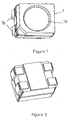
- the LEDs 1 are composed of an illuminating area 1a and electrodes 1b providing the electrical connection.
- the device according to the invention consists mainly of a plastic body 2 on which is fixed a metal cluster 3. An LED 1 is inserted into the metal cluster 3.
- the metal cluster consists of a set of contacts making electrical tracks, this assembly being cut and folded according to the shapes that one wishes to achieve.
- This one-piece assembly is then assembled and separated by an operation called dehuntage.
- bridges also called shunts, connecting the different electrical tracks are cut, thereby obtaining an operational electrical circuit.
- the body 2 may be flat or curved shape, or any other form, according to the aesthetics of the desired scout.
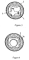
- This body 2 is of a shape such that it allows the insertion of the LED 1 while blocking it. Indeed, it is provided with both openings 4 for positioning the LEDs 1 to be assembled and stops 5 which will stop the LED 1 during its insertion into the body 2.
- the metal cluster 3 which is fixed on the body 2 comprises a contact arm 6 and an arm for positioning and maintaining the LEDs 7. It is provided with holes 8 allowing its attachment to the body 2.
- the contact arm 6 of the metal cluster 3 makes it possible to establish electrical contact with the electrodes 1b located under the LED 1.
- This contact arm 6 is made of an elastic material, which enables it to work with deformation and assures it a good electrical contact on the electrodes 1b.
- the positioning arm 7 of the metal cluster 3 provides electrical contact on the electrodes 1b of the LEDs. This contact is made on the side of the electrodes 1b. Moreover, the positioning arm 7 ensures the positioning of the LED 1 in its housing.
- this arm 7 On its upper part, this arm 7 is provided with a lug 9 which is positioned on the upper part of the electrode 1b of the LED 1, thus ensuring the maintenance of the latter in its housing and its support on the arm of contact 6.
- the product according to the invention makes it possible to ensure electrical contact in at least two points on each electrode of the LED thanks to the contact arm and thanks to the lug located on the holding arm, acting together to maintain contact.
- each arm of the metal cluster provides a thermal role in that they allow the dissipation of the heat emitted by the LED through the electrodes.
- the metal cluster is provided with bridges or shunts. These will be cut when assembling the metal cluster on the plastic body.
- the metal cluster may be provided with one or more LEDs. It can have different shapes fitting the shapes of the plastic body allowing the realization of electrical circuits in three dimensions.
Landscapes
- Led Device Packages (AREA)
Abstract
Description
- La présente invention concerne un dispositif de maintien et de connexion de composants optoélectroniques comme les diodes électroluminescentes (LEDs) du type PLCC2 et PLCC4.
- Habituellement, les composants optoélectroniques, tels que les diodes électroluminescentes, sont fixés sur les circuits imprimés au moyen d'une soudure. Cependant, comme les circuits imprimés destinés à la fixation de diodes électroluminescentes sont rigides et plats, il devient compliqué et coûteux de réaliser des dispositifs d'éclairage ayant une forme spécifique, telle qu'une forme bombée.
- Par ailleurs, lors du montage de ces diodes électroluminescentes sur les circuits imprimés, il est nécessaire d'effectuer plusieurs opérations, à savoir la dépose d'adhésif sur le circuit, la dépose de la diode électroluminescente, la dépose d'étain sur le dispositif qui est ensuite passé en four de soudure. Un contrôle des soudures est ensuite réalisé en fin de montage.
- Ces diverses contraintes augmentent les coûts de production des dispositifs utilisant les composants optoélectroniques, tels que les diodes électroluminescentes, dans la mesure où leur montage est long et parfois compliqué en cas de forme non plane.
- L'invention se propose de remédier à ces divers inconvénients en proposant un dispositif permettant d'assurer à la fois le maintien et la connexion électrique des composants optoélectroniques, tels que les diodes électroluminescentes, tout en assurant une flexibilité au niveau des formes et une simplification du processus de montage.
- A cet effet, la présente invention a pour objet un dispositif de maintien et de connexion des composants optoélectroniques comme les diodes électroluminescentes du type PLCC2 et PLCC4, caractérisé en ce que ledit dispositif est constitué d'un corps sur lequel est disposée une grappe métallique.
- Les diodes électroluminescentes, désignées sous l'abréviation LEDs, peuvent avoir différents types de format. Sous leur forme PLCC2 et PLCC4, les LEDs sont des composant optoélectroniques destinées aux montages en surface.
- On comprendra mieux l'invention en référence aux dessins annexés sur lesquels :
- la figure 1 est une représentation schématique d'une LED vue de dessus,
- la figure 2 est une représentation d'une LED vue de dessous,
- la figure 3 est une représentation du corps,
- la figure 4 est une représentation du corps après insertion de la LED,
- la figure 5 est une représentation de la grappe métallique,
- la figure 6 est une représentation du dessus de la grappe métallique lors de la fixation de la LED,
- la figure 7 est une représentation latérale de la grappe métallique lors de la fixation de la LED.
- Les LEDs 1 sont composées d'une zone éclairante 1a et d'électrodes 1b assurant la connexion électrique.
- Le dispositif selon l'invention est constitué principalement d'un corps 2 en matière plastique sur lequel est fixée une grappe métallique 3. Une LED 1 s'insère dans la grappe métallique 3.
- La grappe métallique est constituée d'un ensemble de contacts réalisant des pistes électriques, cet ensemble étant découpé et plié selon les formes que l'on souhaite réaliser.
- Cet ensemble monobloc est ensuite assemblé et séparé par une opération appelée déshuntage. Lors de cette opération, des ponts, appelés également shunts, reliant les différentes pistes électriques sont coupés, permettant ainsi d'obtenir un circuit électrique opérationnel.
- Par sa composition plastique, le corps 2 pourra être de forme plane ou bombée, ou de toute autre forme, selon l'esthétique de l'éclaireur souhaitée.
- Ce corps 2 est d'une forme telle qu'il permet l'insertion de la LED 1 tout en la bloquant. En effet, il est muni à la fois d'ouvertures 4 destinées au positionnement des LEDs 1 à assembler ainsi que de butées 5 qui vont arrêter la LED 1 lors de son insertion dans le corps 2.
- La grappe métallique 3 qui se fixe sur le corps 2 comporte un bras de contact 6 ainsi qu'un bras destiné au positionnement et au maintien 7 des LEDs. Elle est munie de trous 8 permettant sa fixation au corps 2.
- Le bras de contact 6 de la grappe métallique 3 permet d'établir le contact électrique avec les électrodes 1b situées sous la LED 1. Ce bras de contact 6 est constitué d'une matière élastique, qui lui permet de travailler en déformation et lui assure un bon contact électrique sur les électrodes 1b.
- Le bras de positionnement 7 de la grappe métallique 3 assure quant à lui un contact électrique sur les électrodes 1b des LEDs. Ce contact est réalisé sur le côté des électrodes 1b. Par ailleurs, le bras de positionnement 7 assure le positionnement de la LED 1 dans son logement.
- Sur sa partie supérieure, ce bras 7 est muni d'un ergot 9 qui se positionne sur la partie supérieure de l'électrode 1b de la LED 1, assurant ainsi le maintien de cette dernière dans son logement ainsi que son appui sur le bras de contact 6.
- Le produit selon l'invention permet d'assurer le contact électrique en au moins deux points sur chaque électrode de la LED grâce au bras de contact et grâce à l'ergot situé sur le bras de maintien, agissant ensemble pour maintenir le contact.
- Par ailleurs, chacun des bras de la grappe métallique assure un rôle thermique dans la mesure où ils permettent la dissipation de la chaleur émise par la LED par l'intermédiaire des électrodes.
- Par ailleurs, afin de réaliser le circuit électrique recherché, la grappe métallique est munie de ponts ou de shunts. Ceux-ci seront coupés lors de l'assemblage de la grappe métallique sur le corps plastique.
- La grappe métallique peut être munie d'une ou de plusieurs LEDs. Elle peut avoir différentes formes s'ajustant aux formes du corps plastique permettant la réalisation de circuits électriques en trois dimensions.
- Bien que l'invention ait été décrite avec des moyens de réalisation particuliers, elle comprend tous les équivalents techniques des moyens décrits.
Claims (8)
- Dispositif de maintien et de connexion de composants optoélectroniques, comme les diodes électroluminescentes LEDs du type PLCC2 et PLCC4, caractérisé en ce que ledit dispositif est constitué d'un corps 2 en matière plastique sur lequel est disposée une grappe métallique 3.
- Dispositif de maintien et de connexion selon la revendication 1, caractérisé en ce que le corps 2 est muni d'ouvertures 4 et de butées 5.
- Dispositif de maintien et de connexion selon la revendication 1, caractérisé en ce que la grappe métallique 2 est constituée d'un élément de contact 6 et d'un élément assurant le maintien et le positionnement 7 de la LED 1.
- Dispositif de maintien et de connexion selon la revendication 2, caractérisé en ce que l'élément de contact 6 est constitué de matière élastique.
- Dispositif de maintien et de connexion selon la revendication précédente, caractérisé en ce que l'élément de contact 6 est en relation avec les électrodes 1b situées sous la LED 1.
- Dispositif de maintien et de connexion selon l'une des revendications précédentes, caractérisé en ce que l'élément de positionnement et de maintien 7 est muni d'un ergot 9 sur sa partie supérieure.
- Dispositif de maintien et de connexion selon l'une des revendications précédentes, caractérisé en ce que l'élément de maintien et de positionnement 7 est en relation avec le côté des électrodes 1b de la LED 1.
- Dispositif de maintien et de connexion selon la revendication 4, caractérisé en ce que l'ergot 9 appuie sur la partie supérieure de l'électrode 1b de la LED 1.
Priority Applications (1)
| Application Number | Priority Date | Filing Date | Title |
|---|---|---|---|
| EP05366005.6A EP1744373B1 (fr) | 2005-07-13 | 2005-07-13 | Dispositif de maintien et de connexion de composants optoélectroniques comme les LEDs du type PLCC2 et PLCC4 |
Applications Claiming Priority (1)
| Application Number | Priority Date | Filing Date | Title |
|---|---|---|---|
| EP05366005.6A EP1744373B1 (fr) | 2005-07-13 | 2005-07-13 | Dispositif de maintien et de connexion de composants optoélectroniques comme les LEDs du type PLCC2 et PLCC4 |
Publications (2)
| Publication Number | Publication Date |
|---|---|
| EP1744373A1 true EP1744373A1 (fr) | 2007-01-17 |
| EP1744373B1 EP1744373B1 (fr) | 2018-12-05 |
Family
ID=35609708
Family Applications (1)
| Application Number | Title | Priority Date | Filing Date |
|---|---|---|---|
| EP05366005.6A Expired - Lifetime EP1744373B1 (fr) | 2005-07-13 | 2005-07-13 | Dispositif de maintien et de connexion de composants optoélectroniques comme les LEDs du type PLCC2 et PLCC4 |
Country Status (1)
| Country | Link |
|---|---|
| EP (1) | EP1744373B1 (fr) |
Citations (6)
| Publication number | Priority date | Publication date | Assignee | Title |
|---|---|---|---|---|
| US4303297A (en) * | 1980-03-26 | 1981-12-01 | Eastman Kodak Company | Socket structure for electrical components |
| US5706177A (en) * | 1994-12-24 | 1998-01-06 | Temic Telefunken Microelectronic Gmbh | Multi-terminal surface-mounted electronic device |
| DE10053573A1 (de) * | 2000-10-28 | 2002-05-02 | Hella Kg Hueck & Co | Beleuchtungselement |
| DE10134381A1 (de) * | 2001-07-14 | 2003-01-23 | Hella Kg Hueck & Co | Beleuchtungselement |
| US20050030754A1 (en) * | 2003-08-07 | 2005-02-10 | Licht Harold Jay | Systems, devices, and methods for mounting a light emitting diode |
| FR2870083A1 (fr) * | 2004-05-10 | 2005-11-11 | Sli Miniature Lighting Sa Sa | Dispositif de maintien et de connexion de composants optoelectroniques comme les leds du type plcc2 et plcc4 |
-
2005
- 2005-07-13 EP EP05366005.6A patent/EP1744373B1/fr not_active Expired - Lifetime
Patent Citations (6)
| Publication number | Priority date | Publication date | Assignee | Title |
|---|---|---|---|---|
| US4303297A (en) * | 1980-03-26 | 1981-12-01 | Eastman Kodak Company | Socket structure for electrical components |
| US5706177A (en) * | 1994-12-24 | 1998-01-06 | Temic Telefunken Microelectronic Gmbh | Multi-terminal surface-mounted electronic device |
| DE10053573A1 (de) * | 2000-10-28 | 2002-05-02 | Hella Kg Hueck & Co | Beleuchtungselement |
| DE10134381A1 (de) * | 2001-07-14 | 2003-01-23 | Hella Kg Hueck & Co | Beleuchtungselement |
| US20050030754A1 (en) * | 2003-08-07 | 2005-02-10 | Licht Harold Jay | Systems, devices, and methods for mounting a light emitting diode |
| FR2870083A1 (fr) * | 2004-05-10 | 2005-11-11 | Sli Miniature Lighting Sa Sa | Dispositif de maintien et de connexion de composants optoelectroniques comme les leds du type plcc2 et plcc4 |
Also Published As
| Publication number | Publication date |
|---|---|
| EP1744373B1 (fr) | 2018-12-05 |
Similar Documents
| Publication | Publication Date | Title |
|---|---|---|
| EP2775197B1 (fr) | Dispositif d'éclairage et/ou de signalisation pour véhicule automobile, comportant un guide de lumière | |
| FR2870083A1 (fr) | Dispositif de maintien et de connexion de composants optoelectroniques comme les leds du type plcc2 et plcc4 | |
| EP3002511B1 (fr) | Dispositif à composant semi-conducteur monté sur un dissipateur de chaleur, procédé de montage, et dispositif d'éclairage pour véhicule automobile comportant un tel dispositif | |
| FR2922167A1 (fr) | Module d'eclairage pour un phare ou eclairage d'un vehicule automobile. | |
| FR2998944B1 (fr) | Dispositif d'eclairage et/ou de signalisation pour vehicule automobile | |
| FR3026467B1 (fr) | Module lumineux comportant au moins un composant et un connecteur disposes sur un dissipateur de chaleur, et dispositif d'eclairage pour vehicule automobile comportant un tel module | |
| FR2919916A1 (fr) | Module d'eclairage pour un eclairage a source lumineuse a semi-conducteur et eclairage a source lumineuse a semi-conducteur | |
| WO2014083122A1 (fr) | Dispositif d'éclairage et/ou de signalisation pour véhicule automobile | |
| EP1703188A1 (fr) | Collier de maintien | |
| EP2846079A1 (fr) | Module lumineux pour dispositif d'éclairage et/ou de signalisation | |
| EP3299713B1 (fr) | Systeme d emission de lumiere | |
| EP3299702A1 (fr) | Module optique lumineux de véhicule automobile | |
| EP1744373B1 (fr) | Dispositif de maintien et de connexion de composants optoélectroniques comme les LEDs du type PLCC2 et PLCC4 | |
| EP3211293A1 (fr) | Dispositif de dissipation thermique pour un dispositif lumineux d'un véhicule automobile | |
| US20190250343A1 (en) | Light module for illuminating an outer component of a vehicle, and process for manufacturing such light module | |
| FR2936678A1 (fr) | Lampe a diode electroluminescente | |
| EP2554893B1 (fr) | Dispositif de lampe led et procédé automatisé de fabrication dudit dispositif | |
| FR2849954A1 (fr) | Dispositif de commutation a source lumineuse integree. | |
| FR2887393A1 (fr) | Module source de lumiere et lampe de vehicule | |
| EP3416465A1 (fr) | Ensemble comportant un boitier avant, un boitier arriere, et une carte electronique destinee a etre fixee entre le boitier avant et un boitier arriere | |
| FR2922000A1 (fr) | Procede de fabrication d'une installation d'eclairage | |
| FR2806680A1 (fr) | Feu de signalisation pour vehicule | |
| FR2904731A1 (fr) | Module d'eclairage. | |
| FR3043494A1 (fr) | Systeme lumineux comprenant un circuit imprime souple definissant plusieurs modules munis d'au moins une diode electroluminescente | |
| EP2881290B1 (fr) | Dispositif chauffant pour balai d'essuie-glace d'un véhicule et balai d'essuie-glace le comportant |
Legal Events
| Date | Code | Title | Description |
|---|---|---|---|
| PUAI | Public reference made under article 153(3) epc to a published international application that has entered the european phase |
Free format text: ORIGINAL CODE: 0009012 |
|
| AK | Designated contracting states |
Kind code of ref document: A1 Designated state(s): AT BE BG CH CY CZ DE DK EE ES FI FR GB GR HU IE IS IT LI LT LU LV MC NL PL PT RO SE SI SK TR |
|
| AX | Request for extension of the european patent |
Extension state: AL BA HR MK YU |
|
| 17P | Request for examination filed |
Effective date: 20070126 |
|
| 17Q | First examination report despatched |
Effective date: 20070223 |
|
| AKX | Designation fees paid |
Designated state(s): AT BE BG CH CY CZ DE DK EE ES FI FR GB GR HU IE IS IT LI LT LU LV MC NL PL PT RO SE SI SK TR |
|
| REG | Reference to a national code |
Ref country code: DE Ref legal event code: R079 Ref document number: 602005055089 Country of ref document: DE Free format text: PREVIOUS MAIN CLASS: H01L0033000000 Ipc: H01L0033480000 |
|
| GRAP | Despatch of communication of intention to grant a patent |
Free format text: ORIGINAL CODE: EPIDOSNIGR1 |
|
| STAA | Information on the status of an ep patent application or granted ep patent |
Free format text: STATUS: GRANT OF PATENT IS INTENDED |
|
| RIC1 | Information provided on ipc code assigned before grant |
Ipc: H01L 23/32 20060101ALI20180614BHEP Ipc: H01L 33/48 20100101AFI20180614BHEP Ipc: H01L 33/62 20100101ALI20180614BHEP |
|
| INTG | Intention to grant announced |
Effective date: 20180710 |
|
| GRAS | Grant fee paid |
Free format text: ORIGINAL CODE: EPIDOSNIGR3 |
|
| GRAA | (expected) grant |
Free format text: ORIGINAL CODE: 0009210 |
|
| GRAA | (expected) grant |
Free format text: ORIGINAL CODE: 0009210 |
|
| STAA | Information on the status of an ep patent application or granted ep patent |
Free format text: STATUS: THE PATENT HAS BEEN GRANTED |
|
| AK | Designated contracting states |
Kind code of ref document: B1 Designated state(s): AT BE BG CH CY CZ DE DK EE ES FI FR GB GR HU IE IS IT LI LT LU LV MC NL PL PT RO SE SI SK TR |
|
| REG | Reference to a national code |
Ref country code: GB Ref legal event code: FG4D Free format text: NOT ENGLISH |
|
| REG | Reference to a national code |
Ref country code: CH Ref legal event code: EP |
|
| REG | Reference to a national code |
Ref country code: AT Ref legal event code: REF Ref document number: 1074148 Country of ref document: AT Kind code of ref document: T Effective date: 20181215 |
|
| REG | Reference to a national code |
Ref country code: IE Ref legal event code: FG4D Free format text: LANGUAGE OF EP DOCUMENT: FRENCH |
|
| REG | Reference to a national code |
Ref country code: DE Ref legal event code: R096 Ref document number: 602005055089 Country of ref document: DE |
|
| REG | Reference to a national code |
Ref country code: NL Ref legal event code: MP Effective date: 20181205 |
|
| REG | Reference to a national code |
Ref country code: AT Ref legal event code: MK05 Ref document number: 1074148 Country of ref document: AT Kind code of ref document: T Effective date: 20181205 |
|
| REG | Reference to a national code |
Ref country code: LT Ref legal event code: MG4D |
|
| PG25 | Lapsed in a contracting state [announced via postgrant information from national office to epo] |
Ref country code: LT Free format text: LAPSE BECAUSE OF FAILURE TO SUBMIT A TRANSLATION OF THE DESCRIPTION OR TO PAY THE FEE WITHIN THE PRESCRIBED TIME-LIMIT Effective date: 20181205 Ref country code: BG Free format text: LAPSE BECAUSE OF FAILURE TO SUBMIT A TRANSLATION OF THE DESCRIPTION OR TO PAY THE FEE WITHIN THE PRESCRIBED TIME-LIMIT Effective date: 20190305 Ref country code: ES Free format text: LAPSE BECAUSE OF FAILURE TO SUBMIT A TRANSLATION OF THE DESCRIPTION OR TO PAY THE FEE WITHIN THE PRESCRIBED TIME-LIMIT Effective date: 20181205 Ref country code: AT Free format text: LAPSE BECAUSE OF FAILURE TO SUBMIT A TRANSLATION OF THE DESCRIPTION OR TO PAY THE FEE WITHIN THE PRESCRIBED TIME-LIMIT Effective date: 20181205 Ref country code: FI Free format text: LAPSE BECAUSE OF FAILURE TO SUBMIT A TRANSLATION OF THE DESCRIPTION OR TO PAY THE FEE WITHIN THE PRESCRIBED TIME-LIMIT Effective date: 20181205 Ref country code: LV Free format text: LAPSE BECAUSE OF FAILURE TO SUBMIT A TRANSLATION OF THE DESCRIPTION OR TO PAY THE FEE WITHIN THE PRESCRIBED TIME-LIMIT Effective date: 20181205 |
|
| PG25 | Lapsed in a contracting state [announced via postgrant information from national office to epo] |
Ref country code: SE Free format text: LAPSE BECAUSE OF FAILURE TO SUBMIT A TRANSLATION OF THE DESCRIPTION OR TO PAY THE FEE WITHIN THE PRESCRIBED TIME-LIMIT Effective date: 20181205 Ref country code: GR Free format text: LAPSE BECAUSE OF FAILURE TO SUBMIT A TRANSLATION OF THE DESCRIPTION OR TO PAY THE FEE WITHIN THE PRESCRIBED TIME-LIMIT Effective date: 20190306 |
|
| PG25 | Lapsed in a contracting state [announced via postgrant information from national office to epo] |
Ref country code: NL Free format text: LAPSE BECAUSE OF FAILURE TO SUBMIT A TRANSLATION OF THE DESCRIPTION OR TO PAY THE FEE WITHIN THE PRESCRIBED TIME-LIMIT Effective date: 20181205 |
|
| PG25 | Lapsed in a contracting state [announced via postgrant information from national office to epo] |
Ref country code: PL Free format text: LAPSE BECAUSE OF FAILURE TO SUBMIT A TRANSLATION OF THE DESCRIPTION OR TO PAY THE FEE WITHIN THE PRESCRIBED TIME-LIMIT Effective date: 20181205 Ref country code: PT Free format text: LAPSE BECAUSE OF FAILURE TO SUBMIT A TRANSLATION OF THE DESCRIPTION OR TO PAY THE FEE WITHIN THE PRESCRIBED TIME-LIMIT Effective date: 20190405 Ref country code: IT Free format text: LAPSE BECAUSE OF FAILURE TO SUBMIT A TRANSLATION OF THE DESCRIPTION OR TO PAY THE FEE WITHIN THE PRESCRIBED TIME-LIMIT Effective date: 20181205 Ref country code: CZ Free format text: LAPSE BECAUSE OF FAILURE TO SUBMIT A TRANSLATION OF THE DESCRIPTION OR TO PAY THE FEE WITHIN THE PRESCRIBED TIME-LIMIT Effective date: 20181205 |
|
| PG25 | Lapsed in a contracting state [announced via postgrant information from national office to epo] |
Ref country code: RO Free format text: LAPSE BECAUSE OF FAILURE TO SUBMIT A TRANSLATION OF THE DESCRIPTION OR TO PAY THE FEE WITHIN THE PRESCRIBED TIME-LIMIT Effective date: 20181205 Ref country code: IS Free format text: LAPSE BECAUSE OF FAILURE TO SUBMIT A TRANSLATION OF THE DESCRIPTION OR TO PAY THE FEE WITHIN THE PRESCRIBED TIME-LIMIT Effective date: 20190405 Ref country code: EE Free format text: LAPSE BECAUSE OF FAILURE TO SUBMIT A TRANSLATION OF THE DESCRIPTION OR TO PAY THE FEE WITHIN THE PRESCRIBED TIME-LIMIT Effective date: 20181205 Ref country code: SK Free format text: LAPSE BECAUSE OF FAILURE TO SUBMIT A TRANSLATION OF THE DESCRIPTION OR TO PAY THE FEE WITHIN THE PRESCRIBED TIME-LIMIT Effective date: 20181205 |
|
| REG | Reference to a national code |
Ref country code: DE Ref legal event code: R097 Ref document number: 602005055089 Country of ref document: DE |
|
| PLBE | No opposition filed within time limit |
Free format text: ORIGINAL CODE: 0009261 |
|
| STAA | Information on the status of an ep patent application or granted ep patent |
Free format text: STATUS: NO OPPOSITION FILED WITHIN TIME LIMIT |
|
| PG25 | Lapsed in a contracting state [announced via postgrant information from national office to epo] |
Ref country code: DK Free format text: LAPSE BECAUSE OF FAILURE TO SUBMIT A TRANSLATION OF THE DESCRIPTION OR TO PAY THE FEE WITHIN THE PRESCRIBED TIME-LIMIT Effective date: 20181205 Ref country code: SI Free format text: LAPSE BECAUSE OF FAILURE TO SUBMIT A TRANSLATION OF THE DESCRIPTION OR TO PAY THE FEE WITHIN THE PRESCRIBED TIME-LIMIT Effective date: 20181205 |
|
| 26N | No opposition filed |
Effective date: 20190906 |
|
| PG25 | Lapsed in a contracting state [announced via postgrant information from national office to epo] |
Ref country code: MC Free format text: LAPSE BECAUSE OF FAILURE TO SUBMIT A TRANSLATION OF THE DESCRIPTION OR TO PAY THE FEE WITHIN THE PRESCRIBED TIME-LIMIT Effective date: 20181205 |
|
| REG | Reference to a national code |
Ref country code: CH Ref legal event code: PL |
|
| GBPC | Gb: european patent ceased through non-payment of renewal fee |
Effective date: 20190713 |
|
| PG25 | Lapsed in a contracting state [announced via postgrant information from national office to epo] |
Ref country code: TR Free format text: LAPSE BECAUSE OF FAILURE TO SUBMIT A TRANSLATION OF THE DESCRIPTION OR TO PAY THE FEE WITHIN THE PRESCRIBED TIME-LIMIT Effective date: 20181205 |
|
| REG | Reference to a national code |
Ref country code: BE Ref legal event code: MM Effective date: 20190731 |
|
| PG25 | Lapsed in a contracting state [announced via postgrant information from national office to epo] |
Ref country code: GB Free format text: LAPSE BECAUSE OF NON-PAYMENT OF DUE FEES Effective date: 20190713 |
|
| PG25 | Lapsed in a contracting state [announced via postgrant information from national office to epo] |
Ref country code: BE Free format text: LAPSE BECAUSE OF NON-PAYMENT OF DUE FEES Effective date: 20190731 Ref country code: CH Free format text: LAPSE BECAUSE OF NON-PAYMENT OF DUE FEES Effective date: 20190731 Ref country code: LU Free format text: LAPSE BECAUSE OF NON-PAYMENT OF DUE FEES Effective date: 20190713 Ref country code: LI Free format text: LAPSE BECAUSE OF NON-PAYMENT OF DUE FEES Effective date: 20190731 |
|
| PG25 | Lapsed in a contracting state [announced via postgrant information from national office to epo] |
Ref country code: IE Free format text: LAPSE BECAUSE OF NON-PAYMENT OF DUE FEES Effective date: 20190713 |
|
| PG25 | Lapsed in a contracting state [announced via postgrant information from national office to epo] |
Ref country code: CY Free format text: LAPSE BECAUSE OF FAILURE TO SUBMIT A TRANSLATION OF THE DESCRIPTION OR TO PAY THE FEE WITHIN THE PRESCRIBED TIME-LIMIT Effective date: 20181205 |
|
| PG25 | Lapsed in a contracting state [announced via postgrant information from national office to epo] |
Ref country code: HU Free format text: LAPSE BECAUSE OF FAILURE TO SUBMIT A TRANSLATION OF THE DESCRIPTION OR TO PAY THE FEE WITHIN THE PRESCRIBED TIME-LIMIT; INVALID AB INITIO Effective date: 20050713 |
|
| PGFP | Annual fee paid to national office [announced via postgrant information from national office to epo] |
Ref country code: DE Payment date: 20240828 Year of fee payment: 20 |
|
| PGFP | Annual fee paid to national office [announced via postgrant information from national office to epo] |
Ref country code: FR Payment date: 20240716 Year of fee payment: 20 |
|
| REG | Reference to a national code |
Ref country code: DE Ref legal event code: R079 Ref document number: 602005055089 Country of ref document: DE Free format text: PREVIOUS MAIN CLASS: H01L0033480000 Ipc: H10H0020850000 |
|
| REG | Reference to a national code |
Ref country code: DE Ref legal event code: R071 Ref document number: 602005055089 Country of ref document: DE |