EP1743768B1 - Printing press equipped with movable inking unit - Google Patents
Printing press equipped with movable inking unit Download PDFInfo
- Publication number
- EP1743768B1 EP1743768B1 EP06014084.5A EP06014084A EP1743768B1 EP 1743768 B1 EP1743768 B1 EP 1743768B1 EP 06014084 A EP06014084 A EP 06014084A EP 1743768 B1 EP1743768 B1 EP 1743768B1
- Authority
- EP
- European Patent Office
- Prior art keywords
- gear
- cylinder
- printing
- printing press
- inking unit
- Prior art date
- Legal status (The legal status is an assumption and is not a legal conclusion. Google has not performed a legal analysis and makes no representation as to the accuracy of the status listed.)
- Revoked
Links
Images




Classifications
-
- B—PERFORMING OPERATIONS; TRANSPORTING
- B41—PRINTING; LINING MACHINES; TYPEWRITERS; STAMPS
- B41F—PRINTING MACHINES OR PRESSES
- B41F13/00—Common details of rotary presses or machines
- B41F13/004—Electric or hydraulic features of drives
- B41F13/0045—Electric driving devices
-
- B—PERFORMING OPERATIONS; TRANSPORTING
- B41—PRINTING; LINING MACHINES; TYPEWRITERS; STAMPS
- B41F—PRINTING MACHINES OR PRESSES
- B41F13/00—Common details of rotary presses or machines
- B41F13/0024—Frames
-
- B—PERFORMING OPERATIONS; TRANSPORTING
- B41—PRINTING; LINING MACHINES; TYPEWRITERS; STAMPS
- B41F—PRINTING MACHINES OR PRESSES
- B41F13/00—Common details of rotary presses or machines
- B41F13/008—Mechanical features of drives, e.g. gears, clutches
- B41F13/012—Taking-up backlash
-
- B—PERFORMING OPERATIONS; TRANSPORTING
- B41—PRINTING; LINING MACHINES; TYPEWRITERS; STAMPS
- B41F—PRINTING MACHINES OR PRESSES
- B41F21/00—Devices for conveying sheets through printing apparatus or machines
- B41F21/10—Combinations of transfer drums and grippers
- B41F21/104—Gripper details
-
- B—PERFORMING OPERATIONS; TRANSPORTING
- B41—PRINTING; LINING MACHINES; TYPEWRITERS; STAMPS
- B41F—PRINTING MACHINES OR PRESSES
- B41F31/00—Inking arrangements or devices
- B41F31/004—Driving means for ink rollers
-
- B—PERFORMING OPERATIONS; TRANSPORTING
- B41—PRINTING; LINING MACHINES; TYPEWRITERS; STAMPS
- B41F—PRINTING MACHINES OR PRESSES
- B41F31/00—Inking arrangements or devices
- B41F31/30—Arrangements for tripping, lifting, adjusting, or removing inking rollers; Supports, bearings, or forks therefor
- B41F31/302—Devices for tripping inking devices as a whole
-
- B—PERFORMING OPERATIONS; TRANSPORTING
- B41—PRINTING; LINING MACHINES; TYPEWRITERS; STAMPS
- B41F—PRINTING MACHINES OR PRESSES
- B41F9/00—Rotary intaglio printing presses
- B41F9/02—Rotary intaglio printing presses for multicolour printing
- B41F9/021—Sheet printing presses
-
- B—PERFORMING OPERATIONS; TRANSPORTING
- B41—PRINTING; LINING MACHINES; TYPEWRITERS; STAMPS
- B41P—INDEXING SCHEME RELATING TO PRINTING, LINING MACHINES, TYPEWRITERS, AND TO STAMPS
- B41P2213/00—Arrangements for actuating or driving printing presses; Auxiliary devices or processes
- B41P2213/10—Constitutive elements of driving devices
- B41P2213/11—Motors
-
- B—PERFORMING OPERATIONS; TRANSPORTING
- B41—PRINTING; LINING MACHINES; TYPEWRITERS; STAMPS
- B41P—INDEXING SCHEME RELATING TO PRINTING, LINING MACHINES, TYPEWRITERS, AND TO STAMPS
- B41P2213/00—Arrangements for actuating or driving printing presses; Auxiliary devices or processes
- B41P2213/10—Constitutive elements of driving devices
- B41P2213/20—Gearings
-
- B—PERFORMING OPERATIONS; TRANSPORTING
- B41—PRINTING; LINING MACHINES; TYPEWRITERS; STAMPS
- B41P—INDEXING SCHEME RELATING TO PRINTING, LINING MACHINES, TYPEWRITERS, AND TO STAMPS
- B41P2213/00—Arrangements for actuating or driving printing presses; Auxiliary devices or processes
- B41P2213/70—Driving devices associated with particular installations or situations
- B41P2213/73—Driving devices for multicolour presses
- B41P2213/734—Driving devices for multicolour presses each printing unit being driven by its own electric motor, i.e. electric shaft
Definitions
- This invention relates to a printing press equipped with a movable inking unit which is preferred for offset printing.
- multicolor printing is generally performed by a plurality of plate cylinders arranged in a satellite configuration around a single blanket cylinder.
- the plurality of plate cylinders are disposed in a vertical direction, thus involving a complicated structure.
- an inking unit which supplies inks to the plate cylinders, from a printing unit, thereby ensuring a work space.
- the inking unit has been driven from the printing unit via gears.
- a plurality of gear engagement windows which are provided in opposed surfaces of a frame cover 101 of a printing unit 100 (a drive system of the printing unit 100 is accommodated inside) and a frame cover 103 of an inking unit 102 (a drive system of the inking unit 102 is accommodated inside), are opened and closed with protective covers 104. That is, when the inking unit 102 is thrown on the printing unit 100 to make contact therewith, the protective covers 104 are automatically opened. When the inking unit 102 is thrown off the printing unit 100 to become out of contact, the protective covers 104 are automatically closed. By so doing, a lubricating oil is prevented from scattering (see Japanese Utility Model Application Laid-Open Nos. 1989-174129 , 1989-174133 , 1989-178943 , and 1990-2130 ).
- the above-described printing press faces the problems that while the inking unit 102 is in contact with the printing unit 100, and a gear mechanism is rotated at a high speed under an oil shower to carry out printing, the lubricating oil adheres to the opened protective covers 104, and when the inking unit 102 is thrown off the printing unit 100, the adhering lubricating oil drips from the closed protective covers 104.
- the adjustment of gear engagement between the inking unit 102 and the printing unit 100 has to be made, with the inking unit 102 being in contact with the printing unit 100.
- the gears of the inking unit 102 and the gears of the printing unit 100 repeat engagement and disengagement, thus posing the problem that the accuracy of their engagement is lost in a relatively short time because of wear.
- WO-2005/097503-A2 like the present invention, relates to a printing press equipped with a movable inking unit, and its features are as follows: As shown in [Fig. 24], a wall section 49 supporting inking devices 08 on the right and left sides is detachably supported via a linear guide 15 on a printing unit 01 which supports a pair of image transfer cylinders 06 and a pair of plate cylinders 07. As shown in [Fig. 26] and [Fig. 27], the image transfer cylinders 06 and the plate cylinders 07 are driven by a drive motor 121 via a drive train 122, and the drive train 122 is completely closed by a casing 152. As shown in [Fig. 26], [Fig. 27] and [Fig.
- a friction cylinder 33 of the inking device 08 is driven by a drive motor 128 via a frictional transmission device 136, and the frictional transmission device 136 is completely closed by a casing 153.
- a reciprocating transmission device 162 can be lubricated with oil, or advantageously with grease, in an enclosed space.
- EP-1264686-A1 relates to a printing press equipped with a movable inking unit, and its features are as follows: As shown in [ Fig. 1 ], first and second frame portions 6 and 8 supporting first and second inking devices 4 and 14 are attachable to and detachable from a central frame portion 5 supporting four printing units. Moreover, column 2 on lines 28 to 36 describes: the inking device is driven by one individual drive motor, and a plate cylinder and a blanket cylinder are driven by two independent drive motors.” Hence, the reference describes that "the first and second inking devices 4 and 14 can be thrown on and thrown off the printing unit", and that "the inking device is driven by one individual drive motor, and the plate cylinder and the blanket cylinder are driven by two independent drive motors.
- JP-2-002130-U relates to a printing press equipped with a movable inking unit, and its features are as follows:
- a roller lever 43 is turned clockwise by a cam 45, whereby a first swing arm 21 is pivoted clockwise about a first shaft 23.
- a connecting member 27 connected to the first swing arm 21 via a first rotating joint 25 is turned counterclockwise.
- the gripper 11 connected to the connecting member 27 via a rotating joint 35 is pushed by a spring member 41, and turned clockwise thereby.
- the sheet to be printed is held between the gripper leading end 16 and the support surface 17 of the support pad 13, as shown in [ Fig. 1 ] (b).
- the roller lever 43 is further turned clockwise by the cam 45, whereby the first swing arm 21 is further pivoted clockwise about the first shaft 23.
- the connecting member 27 connected to the first swing arm 21 via the first rotating joint 25 is further turned counter-clockwise.
- the support pad 13 mounted immovably on the connecting member 27 is turned counterclockwise as in [ Fig. 1 ] (c) and, with the gripper leading end 16 being pushed against the support surface 17 by the spring member 41, the support pad 13 and the gripper 11 completely crawl below a cylinder sheath contour 49.
- the reference only describes "a gripper device located within the circumference".
- EP-613775-A1 this reference relates to a gear mechanism of a printing unit of a printing press. Its features are as follows: "In a gear mechanism of a printing unit of a printing press, as in [ Fig. 1 ], a blanket cylinder gear 84 fixed to a shaft 56 of a blanket cylinder 16 to be driven by a motor 24 meshes with a plate cylinder gear 70 fixed to a shaft 54 of a plate cylinder 14 to drive the plate cylinder 14 rotationally. As in [ Fig. 2 ], moreover, a gear 92 meshing with the blanket cylinder gear 84 is fixed in an unpivotable manner to a shaft 96 supported pivotably by a frame 104.
- a torsion spring 122 is provided between the shaft 96 and a cylindrical portion 110 of a gear 108 pivotably supported on the frame 104.
- a preload permitting pivots in reverse directions is imposed.
- the gear 108 meshes with the gear 76 fixed to the shaft 54 of the plate cylinder 14 via a gear 136, applying a preload to the shaft 54 of the plate cylinder 14 in a direction opposite to the direction of drive by the blanket cylinder gear 84, thus preventing separation between the blanket cylinder gear 84 and the plate cylinder gear 70.
- EP-1088657-A1 relates to a printing press equipped with a movable inking unit, and its features are as follows: As shown in [ Fig. 2 ], a second subframe 36 provided with ink supply devices 34a to 34c is movable to approach and separate from a main frame 30 provided with an impression cylinder 31, an intaglio cylinder 32 and chablon rollers 33a to 33c. Separately from the second subframe 36, a first subframe 35 provided with an ink supply device 34d and a chablon roller 3 3d is movable to approach and separate from the main frame 30 provided with the impression cylinder 31 and the intaglio cylinder 32.
- EP-1442878-A1 this reference relates to a drive mechanism for a selector cylinder of an intaglio printing press equipped with a fixed inking device, and its features are as follows: As shown in [ Fig. 2 ]2A, a selector cylinder 10 of an inking device, and a duct roller 11 are driven individually by a drive motor 20. Alternatively, as shown in Fig. 2B , the selector cylinder 10 of the inking device is driven independently by a drive motor 25.
- this reference relates to a gripping system of an impression cylinder of a sheet-fed printing press. Its features and actions are as follows: During routine printing, as shown in [ Fig. 2 ], a roll lever 11 fixed to a gripping shaft 9 of a gripping system 100 of an impression cylinder 3 opposes a concave portion of a cam 4 nonrotatably supported on a blanket cylinder 2. Thus, the gripping system 100 can grip or release a printing sheet. If the rotational phases of the blanket cylinder 2 and the impression cylinder 3 deviate from each other, the roll lever 11 fixed to the gripping shaft 9 passes over the cam 4, as in [ Fig. 3 ], with the result that the roller lever 11 is turned clockwise.
- the gripping shaft 9 is also turned clockwise, and a gripper 8 pushes down a gripping contact edge 10 into a sinking concave portion 14 against the impact resilient force of a compression spring 12, thereby locating the gripper 8 and the gripping contact edge 10 into the contour of the impression cylinder 3.
- WO 2005/005149-A2 discloses a printing unit for a web-offset press.
- the printing unit comprises plate an blanket cylinders arranged in couples to print on both sides of the paper.
- EP 0 873 866 A1 discloses an intaglio printing machine having ink cylinders and plate cylinders of a predefined size.
- EP 0 699 524 A2 discloses an offset web printing machine wherein all cylinders of a printing unit are driven by a separate electromotor.
- DE 1 124 053 B relates to register holding means for a multicolor rotary printing press.
- the present invention has been proposed in light of the above-described circumstances and provides a printing press equipped with a movable inking unit which can prevent oil leakage of the printing unit and the inking unit and can maintain their machine accuracy satisfactorily for a long term.
- a first aspect of the present invention is a printing press equipped with a movable inking unit as claimed in claim 1.
- the first drive source and the second drive source may be motors driven and controlled by a control device such that the speed of the cylinders of the printing unit and the speed of the ink rollers are equal to each other.
- the printing unit may be composed of a plate cylinder, and an opposed cylinder opposing the plate cylinder, and the printing press may further comprise a third drive source for driving the plate cylinder.
- the third drive source may be a motor driven and controlled by a control device such that the plate cylinder and the opposed cylinder are synchronized with each other.
- the opposed cylinder may have a gripper device for transporting a material to be printed, and when the gripper device holds the material to be printed, an outermost peripheral portion of the gripper device may be located inwardly, in the radial direction of the opposed cylinder, of an outer peripheral surface of the opposed cylinder.
- the printing unit may be composed of a plate cylinder, and an opposed cylinder opposing the plate cylinder, and a gear fixed to a shaft of the plate cylinder for rotationally driving the plate cylinder may be an anti-backlash gear.
- the anti-backlash gear may have a first gear fixed to the shaft of the plate cylinder, a second gear adjacent to the first gear to be relatively rotatable and having an identical number of teeth to the number of teeth of the first gear, and a plurality of elastic members arranged at equal intervals in a circumferential direction and having one end supported by the first gear and another end supported by the second gear.
- the printing unit and the movable inking unit are independently driven, and the covers accommodating the respective drive systems have their opposed surfaces entirely closed.
- oil leakage can be prevented.
- gear engagement between the drive systems does not take place.
- the machine accuracy of the printing unit and the inking unit can be maintained satisfactorily for a long term.
- Fig. 1 is a side view of a printing press equipped with a movable inking unit, showing Embodiment 1 of the present invention.
- Fig. 2 is a view showing the operating state of the inking unit.
- Fig. 3 is a perspective view of the inking unit.
- Fig. 4 is a side view of essential parts of a printing unit.
- a printing press 1 of the present invention comprises a feeder 2, a printing section (hereinafter referred to as a printing unit) 3, a delivery unit 4, a feed side inking unit (hereinafter referred to as a feed side inker) 5A, and a delivery side inking unit (hereinafter referred to as a delivery side inker) 5B.
- the feeder 2 and the delivery unit 4 are connected together by a pair of (i.e., right and left) beds extending on a floor surface.
- a blanketed impression cylinder (opposed cylinder) 7 and a blanket cylinder (opposed cylinder) 8 are journaled in contact with each other.
- Four plate cylinders 9 and four plate cylinders 10 are arranged in a satellite configuration in contact with the circumferential surfaces of the blanketed impression cylinder 7 and the blanket cylinder 8, respectively.
- the feed side inker 5A and the delivery side inker 5B are located on both sides of the printing unit 3, with the printing unit 3 being placed between the inkers 5A and 5B.
- the inkers 5A and 5B are placed via a plurality of rollers 12A and 12B on rails 11A and 11B laid on the beds 6, 6.
- the inkers 5A and 5B are moved along the rails 11A and 11B, whereby the inkers 5A and 5B can approach and leave the printing unit 3.
- the inkers 5A, 5B have a plurality of inking devices 13A, 13B and a plurality of dampeners 14A, 14B corresponding to the plurality of plate cylinders 9, 10.
- the inkers 5A, 5B are moved toward the printing unit 3 and connected to the printing unit 3, their final rollers contact the plate cylinders 9, 10.
- paper (a material to be printed) fed from the feeder 2 is transported along a path shown by arrows in the drawing, namely, along the circumferential surfaces of transfer cylinders 15 to 17, the blanketed impression cylinder 7, and a delivery cylinder 18.
- transfer cylinders 15 to 17 the blanketed impression cylinder 7
- delivery cylinder 18 the paper is passed at the point of contact between the blanketed impression cylinder 7 and the blanket cylinder 8 from above toward below, both surfaces of the paper are printed simultaneously.
- the cylinders of the printing unit 3 such as the blanketed impression cylinder 7 and the blanket cylinder 8, except the plate cylinders 9 and 10, are rotationally driven by a rotary encoder-equipped motor (first drive source) 20 via a gear mechanism (first drive system; not shown).
- the plate cylinders 9, 10 are rotationally driven by a rotary encoder-equipped motor (third drive source) 21 via a gear mechanism (not shown). That is, the plate cylinders 9, 10 are independently driven in the printing unit 3.
- the ink rollers and dampening rollers of the inking devices 13A, 13B and the dampeners 14A, 14B in the inkers 5A, 5B are rotationally driven by rotary encoder-equipped motors (second drive source) 22A, 22B via gear mechanisms (second drive system; not shown). That is, the gear mechanism of the inkers 5A, 5B is completely cut off from the gear mechanism of the printing unit 3.
- the motors 20 to 22A, 22B are driven and controlled by a control device 23, such as a microcomputer, in the following manner: At the time of printing when the inkers 5A, 5B are connected to the printing unit 3, the plate cylinders 9, 10 are controlled in synchronism with other cylinders, such as the blanketed impression cylinder 7 and the blanket cylinder 8.
- the ink rollers and the dampening rollers of the inking devices 13A, 13B and the dampeners 14A, 14B are controlled to be consistent in speed with the plate cylinders 9, 10 and the other cylinders such as the blanketed impression cylinder 7 and the blanket cylinder 8.
- the plate cylinders 9, 10 of the printing unit 3 the other cylinders, such as the blanketed impression cylinder 7 and the blanket cylinder 8 , and the ink rollers and the dampening rollers of the inking devices 13A, 13B and the dampeners 14A, 14B are independently driven.
- the gear mechanisms of the inkers 5A, 5B are housed inside frame covers (second covers) 26A, 26B annexed to outer side surfaces of frames 25A, 25B of the inkers 5A, 5B.
- the gear mechanisms of the printing unit 3 are housed inside a frame cover (first cover) 27 annexed to an outer side surface of a frame (not shown) of the printing unit 3.
- Opposed surfaces (connecting surfaces) 26a, 26b, 27a of the frame covers 26A, 26B of the inkers 5A, 5B and the frame cover 27 of the printing unit 3 are entirely closed with respect to each other. That is, the plurality of gear engagement windows opened and closed with the protective covers 104, as shown in Figs. 8 and 9 , are not formed.
- the blanketed impression cylinder 7 for transporting paper in the printing unit 3 has a gripper device 28 in a gap 7a, the gripper device 28 being composed of a gripper pad 28a, a gripper holder 28b, and a gripper 28c.
- the gripper device 28 is set such that the gripper 28c, which becomes an outermost peripheral portion of the gripper device 28, is located inwardly, in the radial direction of the blanketed impression cylinder 7, of the outer peripheral surface (effective impression area) 7b of the blanketed impression cylinder 7, when the gripper 28c holds the paper 7.
- the outer peripheral surface 7b of the blanketed impression cylinder 7 is set to be larger in diameter than the outer peripheral surface of an ordinary blanket cylinder or the like (see a dashed dotted line in the drawing) .
- the gear mechanism of the plate cylinders 9, 10 in the printing unit 3 is driven by the rotary encoder-equipped motor 21
- the gear mechanism of the other cylinders such as the blanketed impression cylinder 7 and the blanket cylinder 8
- the gear mechanisms of the inking devices 13A, 13B and the dampeners 14A, 14B in the inkers 5A, 5B are driven by the rotary encoder-equipped motors 22A, 22B.
- the respective gear mechanisms are driven by dedicated motors.
- the frame cover 27 accommodating the gear mechanisms of the printing unit 3 and the frame covers 26A, 26B accommodating the gear mechanisms of the inkers 5A, 5B have their opposed surfaces entirely closed, so that oil leakage is reliably prevented. Moreover, no gear engagement takes place between their gear mechanisms. Thus, no wear due to throw-on and throw-off occurs, and there is no need for adjustment of engagement. Consequently, the machine accuracies of the printing unit 3 and the inkers 5A, 5B can be maintained satisfactorily for long periods, and the burden on the operator can be lessened.
- the gear mechanism of the plate cylinders 9, 10 is driven by the rotary encoder-equipped motor 21 independently of the gear mechanism of the other cylinders such as the blanketed impression cylinder 7 and the blanket cylinder 8, as stated earlier. By so doing, relative movement between the blanketed impression cylinder 7 and the plate cylinder 9 is avoided.
- the plate cylinders 9, 10 are driven by the dedicated rotary encoder-equipped motor 21, as mentioned above, the problem arises that the rotation phases of the plate cylinder 9 and the blanketed impression cylinder 7 are shifted with respect to each other during emergency shutdown of the printing press 1. As a result, the gripper 28c of the blanketed impression cylinder 7 interferes with the circumferential surface of the plate cylinder 9 or the plate mounted on the plate cylinder 9, thereby damaging or injuring it.
- the gripper 28c constituting the outermost peripheral portion of the gripper device 28 in the blanketed impression cylinder 7 is set to be located inwardly, in the radial direction of the blanketed impression cylinder 7, of the outer peripheral surface (effective impression area) 7b of the blanketed impression cylinder 7, as described earlier.
- the gripper 28c of the blanketed impression cylinder 7 is prevented from interfering with the circumferential surface of the plate cylinder 9 or the plate mounted on the plate cylinder 9.
- the plate cylinders 9, 10 are driven collectively by the single motor 21 having the rotary encoder.
- the plate cylinders 9 opposing the blanketed impression cylinder 7 may be driven by a motor, and the plate cylinders 10 opposing the blanket cylinder 8 may be driven by another motor.
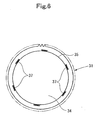
- Fig. 5 is a front view of essential parts of the plate cylinder, showing Embodiment 2 of the present invention.
- Fig. 6 is a view taken on line A-A in Fig. 5 .
- Embodiment 1 This is an embodiment in which the independent driving of the plate cylinders 9, 10 by the motor in Embodiment 1 is not performed; an anti-backlash gear 31 involving no backlash (without so-called play) is used as a gear fixed to a shaft 30 of the plate cylinder 9 or 10 for rotationally driving the plate cylinder 9 or 10; and this gear 31 is linked to the gear mechanism of the other cylinders, such as the blanketed impression cylinder 7 and the blanket cylinder 8, and is rotationally driven by the rotary encoder-equipped motor 20.
- Other features are the same as those in Embodiment 1.
- the anti-backlash gear 31 has a first gear 34 fixed to the shaft 30 of the plate cylinder 9 or 10 by a key 32 and a bolt 33 ; a second gear 36 fitted onto an outer peripheral step portion 35 of the first gear 34 to be relatively rotatable and unremovable by twisting, the second gear 36 having the same number of gear teeth as that of the first gear 34; and a plurality of (six in the illustrated example) elastic members 37 arranged at equal intervals in the circumferential direction and having one end supported by the first gear 34 and the other end supported by the second gear 36.
- the second gear 36 urged by the elastic members 37, always follows a spur gear engaging the first and second gears 34 and 36, whereby backlash is eliminated.
- the gear mechanisms of the printing unit 3 and the gear mechanisms of the inkers 5A, 5B are driven independently, whereby the same actions and effects as those in Embodiment 1 are obtained.
- the relative movement between the blanketed impression cylinder 7 and the plate cylinder 9, which is generated by independently driving the gear mechanisms of the printing unit 3 and the gear mechanisms of the inkers 5A, 5B, can be effectively avoided by the anti-backlash gear 31.
- a printing trouble such as doubling, can be prevented.
- a tension spring or a compression spring is generally used as the elastic member 37.
- the elastic member 37 there is no shift in rotation phase between the plate cylinder 9 and the blanketed impression cylinder 7 even during emergency shutdown, unlike Embodiment 1.
- the outermost peripheral portion of the gripper device 28 of the blanketed impression cylinder 7 is inward, in the radial direction of the blanketed impression cylinder 7, of the outer peripheral surface 7b of the blanketed impression cylinder 7, as in Embodiment 1.
- Fig. 7 is a side view of a printing press equipped with a movable inking unit, showing Embodiment 3 of the present invention.
Landscapes
- Engineering & Computer Science (AREA)
- Mechanical Engineering (AREA)
- Rotary Presses (AREA)
- Inking, Control Or Cleaning Of Printing Machines (AREA)
Description
- This invention relates to a printing press equipped with a movable inking unit which is preferred for offset printing.
- In a printing press for printing securities, multicolor printing is generally performed by a plurality of plate cylinders arranged in a satellite configuration around a single blanket cylinder. In this type of printing press, the plurality of plate cylinders are disposed in a vertical direction, thus involving a complicated structure. To increase the efficiencies of operations such as plate replacement and cleaning, it is necessary to separate an inking unit, which supplies inks to the plate cylinders, from a printing unit, thereby ensuring a work space.
- Conventionally, the inking unit has been driven from the printing unit via gears. Thus, as shown in
Figs. 8 and9 , for example, a plurality of gear engagement windows, which are provided in opposed surfaces of aframe cover 101 of a printing unit 100 (a drive system of theprinting unit 100 is accommodated inside) and aframe cover 103 of an inking unit 102 (a drive system of theinking unit 102 is accommodated inside), are opened and closed withprotective covers 104. That is, when the inkingunit 102 is thrown on theprinting unit 100 to make contact therewith, theprotective covers 104 are automatically opened. When theinking unit 102 is thrown off theprinting unit 100 to become out of contact, theprotective covers 104 are automatically closed. By so doing, a lubricating oil is prevented from scattering (see Japanese Utility Model Application Laid-Open Nos.1989-174129 1989-174133 1989-178943 1990-2130 - The above-described printing press, however, faces the problems that while the inking
unit 102 is in contact with theprinting unit 100, and a gear mechanism is rotated at a high speed under an oil shower to carry out printing, the lubricating oil adheres to the openedprotective covers 104, and when the inkingunit 102 is thrown off theprinting unit 100, the adhering lubricating oil drips from the closedprotective covers 104. - Moreover, the adjustment of gear engagement between the
inking unit 102 and theprinting unit 100 has to be made, with the inkingunit 102 being in contact with theprinting unit 100. This poses the problem that the adjusting operation is difficult, takes time, and burdens an operator. Furthermore, the gears of the inkingunit 102 and the gears of theprinting unit 100 repeat engagement and disengagement, thus posing the problem that the accuracy of their engagement is lost in a relatively short time because of wear. -
WO-2005/097503-A2 , like the present invention, relates to a printing press equipped with a movable inking unit, and its features are as follows: As shown in [Fig. 24], a wall section 49 supporting inking devices 08 on the right and left sides is detachably supported via alinear guide 15 on a printing unit 01 which supports a pair of image transfer cylinders 06 and a pair of plate cylinders 07. As shown in [Fig. 26] and [Fig. 27], the image transfer cylinders 06 and the plate cylinders 07 are driven by a drive motor 121 via a drive train 122, and the drive train 122 is completely closed by a casing 152. As shown in [Fig. 26], [Fig. 27] and [Fig. 32], moreover, afriction cylinder 33 of the inking device 08 is driven by a drive motor 128 via a frictional transmission device 136, and the frictional transmission device 136 is completely closed by a casing 153. Furthermore, the paragraph [0179] ofJP-A-2007-531647 -
EP-1264686-A1 relates to a printing press equipped with a movable inking unit, and its features are as follows: As shown in [Fig. 1 ], first andsecond frame portions devices 4 and 14 are attachable to and detachable from a central frame portion 5 supporting four printing units. Moreover,column 2 onlines 28 to 36 describes: the inking device is driven by one individual drive motor, and a plate cylinder and a blanket cylinder are driven by two independent drive motors." Hence, the reference describes that "the first and secondinking devices 4 and 14 can be thrown on and thrown off the printing unit", and that "the inking device is driven by one individual drive motor, and the plate cylinder and the blanket cylinder are driven by two independent drive motors. -
JP-2-002130-U - As shown in
Fig. 7 , aninking device unit 15 can be thrown on and thrown off a printing press body 13. When printing is to be done, theinking device unit 15 is moved toward the printing press body 13. At this time, as inFig. 4 , a dog 45 provided on theinking device unit 15 turns on a limit switch 46 provided on the printing press body 13. As a result, a rotary solenoid 42 inFig. 1 is actuated to open aprotective cover 37 inFig. 4 . Thus, adrive gear 27 on the side of the printing press body 13 and a drivengear 28 on the side of the inkingdevice unit 15 mesh, so that each roller of theinking device unit 15 is driven by a drive device of the printing press body 13. For plate replacement or maintenance, the inkingdevice unit 15 is moved away from the printing press body 13. At this time, as inFig. 4 , the dog 45 provided on theinking device unit 15 separates from the limit switch 46 provided on the printing press body 13, turning off the limit switch 46. As a result, the rotary solenoid 42 inFig. 1 is operated in the reverse direction to close theprotective cover 37 inFig. 4 , thereby preventing a lubricating oil to drip from agear window 34. The reference (D3)JP-2-002130-U -
US-2002/112627-A1 this reference relates to a gripper of a cylinder of a printing press, the gripper acting together with an opposed cylinder such as a rubber blanket cylinder, a gravure printing cylinder, or a flexographic printing cylinder. Its features and actions will be described below. Other embodiments described in [Fig. 2 ] and [Fig. 3 ] are basically the same in actions as the embodiment described in [Fig. 1 ]. In the following descriptions, therefore, only the embodiment of [Fig. 1 ] will be explained: As shown in [Fig. 1 ] (a), a leadingend 16 of a gripper 11 separates from asupport surface 17 of a gripper support pad 13 to remove a sheet to be printed. Then, a roller lever 43 is turned clockwise by a cam 45, whereby afirst swing arm 21 is pivoted clockwise about afirst shaft 23. A connectingmember 27 connected to thefirst swing arm 21 via a first rotating joint 25 is turned counterclockwise. The gripper 11 connected to the connectingmember 27 via a rotatingjoint 35 is pushed by a spring member 41, and turned clockwise thereby. Thus, the sheet to be printed is held between thegripper leading end 16 and thesupport surface 17 of the support pad 13, as shown in [Fig. 1 ] (b). Then, the roller lever 43 is further turned clockwise by the cam 45, whereby thefirst swing arm 21 is further pivoted clockwise about thefirst shaft 23. The connectingmember 27 connected to thefirst swing arm 21 via the first rotating joint 25 is further turned counter-clockwise. The support pad 13 mounted immovably on the connectingmember 27 is turned counterclockwise as in [Fig. 1 ] (c) and, with thegripper leading end 16 being pushed against thesupport surface 17 by the spring member 41, the support pad 13 and the gripper 11 completely crawl below a cylinder sheath contour 49. Hence, the reference only describes "a gripper device located within the circumference". -
EP-613775-A1 Fig. 1 ], a blanket cylinder gear 84 fixed to a shaft 56 of ablanket cylinder 16 to be driven by a motor 24 meshes with a plate cylinder gear 70 fixed to a shaft 54 of a plate cylinder 14 to drive the plate cylinder 14 rotationally. As in [Fig. 2 ], moreover, a gear 92 meshing with the blanket cylinder gear 84 is fixed in an unpivotable manner to a shaft 96 supported pivotably by aframe 104. A torsion spring 122 is provided between the shaft 96 and a cylindrical portion 110 of a gear 108 pivotably supported on theframe 104. Thus, a preload permitting pivots in reverse directions is imposed. The gear 108 meshes with the gear 76 fixed to the shaft 54 of the plate cylinder 14 via a gear 136, applying a preload to the shaft 54 of the plate cylinder 14 in a direction opposite to the direction of drive by the blanket cylinder gear 84, thus preventing separation between the blanket cylinder gear 84 and the plate cylinder gear 70. -
EP-1088657-A1 relates to a printing press equipped with a movable inking unit, and its features are as follows: As shown in [Fig. 2 ], asecond subframe 36 provided with ink supply devices 34a to 34c is movable to approach and separate from amain frame 30 provided with animpression cylinder 31, anintaglio cylinder 32 and chablon rollers 33a to 33c. Separately from thesecond subframe 36, afirst subframe 35 provided with an ink supply device 34d and achablon roller 3 3d is movable to approach and separate from themain frame 30 provided with theimpression cylinder 31 and theintaglio cylinder 32. -
EP-1442878-A1 this reference relates to a drive mechanism for a selector cylinder of an intaglio printing press equipped with a fixed inking device, and its features are as follows: As shown in [Fig. 2 ]2A, aselector cylinder 10 of an inking device, and a duct roller 11 are driven individually by adrive motor 20. Alternatively, as shown inFig. 2B , theselector cylinder 10 of the inking device is driven independently by a drive motor 25. -
DE-20 2004 018313-U1 this reference relates to a gripping system of an impression cylinder of a sheet-fed printing press. Its features and actions are as follows: During routine printing, as shown in [Fig. 2 ], a roll lever 11 fixed to agripping shaft 9 of agripping system 100 of animpression cylinder 3 opposes a concave portion of acam 4 nonrotatably supported on ablanket cylinder 2. Thus, thegripping system 100 can grip or release a printing sheet. If the rotational phases of theblanket cylinder 2 and theimpression cylinder 3 deviate from each other, the roll lever 11 fixed to the grippingshaft 9 passes over thecam 4, as in [Fig. 3 ], with the result that the roller lever 11 is turned clockwise. As a result, thegripping shaft 9 is also turned clockwise, and agripper 8 pushes down a grippingcontact edge 10 into a sinking concave portion 14 against the impact resilient force of a compression spring 12, thereby locating thegripper 8 and the grippingcontact edge 10 into the contour of theimpression cylinder 3. -
DE-101 51 490 -Al this reference relates to a gear mechanism of a transfer cylinder equipped with a diagonal register of a printing press. Its features are as follows: As shown inFigs. 4 to Fig. 6 , a transfer cylinder 13a of a printing press and its gear 19a are connected by universal joints 25, 26 ormetal film couplings eccentric body 18 of a diagonal register 12, backlash of the gear mechanism does not change, with the result that a rotating force is transmitted without fail. -
WO 2005/005149-A2 discloses a printing unit for a web-offset press. The printing unit comprises plate an blanket cylinders arranged in couples to print on both sides of the paper. -
EP 0 873 866 A1 discloses an intaglio printing machine having ink cylinders and plate cylinders of a predefined size. -
EP 0 699 524 A2 discloses an offset web printing machine wherein all cylinders of a printing unit are driven by a separate electromotor. -
DE 1 124 053 B relates to register holding means for a multicolor rotary printing press. - The present invention has been proposed in light of the above-described circumstances and provides a printing press equipped with a movable inking unit which can prevent oil leakage of the printing unit and the inking unit and can maintain their machine accuracy satisfactorily for a long term.
- A first aspect of the present invention is a printing press equipped with a movable inking unit as claimed in claim 1.
- According to a second aspect of the present invention, the first drive source and the second drive source may be motors driven and controlled by a control device such that the speed of the cylinders of the printing unit and the speed of the ink rollers are equal to each other.
- According to a third aspect of the present invention, the printing unit may be composed of a plate cylinder, and an opposed cylinder opposing the plate cylinder, and the printing press may further comprise a third drive source for driving the plate cylinder.
- According to a fourth aspect of the present invention, the third drive source may be a motor driven and controlled by a control device such that the plate cylinder and the opposed cylinder are synchronized with each other.
- According to a fifth aspect of the present invention, the opposed cylinder may have a gripper device for transporting a material to be printed, and when the gripper device holds the material to be printed, an outermost peripheral portion of the gripper device may be located inwardly, in the radial direction of the opposed cylinder, of an outer peripheral surface of the opposed cylinder.
- According to a sixth aspect of the present invention, the printing unit may be composed of a plate cylinder, and an opposed cylinder opposing the plate cylinder, and a gear fixed to a shaft of the plate cylinder for rotationally driving the plate cylinder may be an anti-backlash gear.
- According to a seventh aspect of the present invention, the anti-backlash gear may have a first gear fixed to the shaft of the plate cylinder, a second gear adjacent to the first gear to be relatively rotatable and having an identical number of teeth to the number of teeth of the first gear, and a plurality of elastic members arranged at equal intervals in a circumferential direction and having one end supported by the first gear and another end supported by the second gear.
- According to the printing press equipped with the movable inking unit concerned with the present invention, the printing unit and the movable inking unit are independently driven, and the covers accommodating the respective drive systems have their opposed surfaces entirely closed. Thus, oil leakage can be prevented. Moreover, gear engagement between the drive systems does not take place. Thus, the machine accuracy of the printing unit and the inking unit can be maintained satisfactorily for a long term.
- The present invention will become more fully understood from the detailed description given hereinbelow and wherein:
-
Fig. 1 is a side view of a printing press equipped with a movable inking unit, showing Embodiment 1 of the present invention; -
Fig. 2 is a view showing the operating state of the inking unit; -
Fig. 3 is a perspective view of the inking unit; -
Fig. 4 is a side view of essential parts of a printing unit; -
Fig. 5 is a front view of essential parts of a plate cylinder, showingEmbodiment 2 of the present invention; -
Fig. 6 is a view taken on line A-A inFig. 5 ; -
Fig. 7 is a side view of a printing press equipped with a movable inking unit, showingEmbodiment 3 of the present invention; -
Fig. 8 is a side view of essential parts of a printing press equipped with a movable inking unit, showing a conventional example; and -
Fig. 9 is a perspective view of the movable inking unit, showing the conventional example. - A printing press equipped with a movable inking unit according to the present invention will now be described in detail by embodiments with reference to the accompanying drawings.
-
Fig. 1 is a side view of a printing press equipped with a movable inking unit, showing Embodiment 1 of the present invention.Fig. 2 is a view showing the operating state of the inking unit.Fig. 3 is a perspective view of the inking unit.Fig. 4 is a side view of essential parts of a printing unit. - As shown in
Fig. 1 , a printing press 1 of the present invention comprises afeeder 2, a printing section (hereinafter referred to as a printing unit) 3, adelivery unit 4, a feed side inking unit (hereinafter referred to as a feed side inker) 5A, and a delivery side inking unit (hereinafter referred to as a delivery side inker) 5B. Thefeeder 2 and thedelivery unit 4 are connected together by a pair of (i.e., right and left) beds extending on a floor surface. - In the
printing unit 3 , a blanketed impression cylinder (opposed cylinder) 7 and a blanket cylinder (opposed cylinder) 8 are journaled in contact with each other. Fourplate cylinders 9 and fourplate cylinders 10 are arranged in a satellite configuration in contact with the circumferential surfaces of the blanketedimpression cylinder 7 and theblanket cylinder 8, respectively. - The
feed side inker 5A and thedelivery side inker 5B are located on both sides of theprinting unit 3, with theprinting unit 3 being placed between theinkers inkers rollers rails beds inkers rails inkers printing unit 3. - The
inkers devices dampeners plate cylinders printing unit 3 and connected to theprinting unit 3, their final rollers contact theplate cylinders - Thus, paper (a material to be printed) fed from the
feeder 2 is transported along a path shown by arrows in the drawing, namely, along the circumferential surfaces oftransfer cylinders 15 to 17, the blanketedimpression cylinder 7, and adelivery cylinder 18. When the paper is passed at the point of contact between theblanketed impression cylinder 7 and theblanket cylinder 8 from above toward below, both surfaces of the paper are printed simultaneously. - According to the present embodiment, the cylinders of the
printing unit 3, such as the blanketedimpression cylinder 7 and theblanket cylinder 8, except theplate cylinders plate cylinders plate cylinders printing unit 3. - The ink rollers and dampening rollers of the
inking devices dampeners inkers printing unit 3. - The
motors 20 to 22A, 22B are driven and controlled by acontrol device 23, such as a microcomputer, in the following manner: At the time of printing when theinkers printing unit 3, theplate cylinders impression cylinder 7 and theblanket cylinder 8. The ink rollers and the dampening rollers of theinking devices dampeners plate cylinders impression cylinder 7 and theblanket cylinder 8. - At the time of maintenance (cleaning, plate replacement, etc.) when the
inkers printing unit 3, on the other hand, theplate cylinders printing unit 3, the other cylinders, such as the blanketedimpression cylinder 7 and theblanket cylinder 8 , and the ink rollers and the dampening rollers of theinking devices dampeners - As shown in
Figs. 2 and3 , the gear mechanisms of the inkers 5A, 5B are housed inside frame covers (second covers) 26A, 26B annexed to outer side surfaces offrames printing unit 3 are housed inside a frame cover (first cover) 27 annexed to an outer side surface of a frame (not shown) of theprinting unit 3. Opposed surfaces (connecting surfaces) 26a, 26b, 27a of the frame covers 26A, 26B of the inkers 5A, 5B and theframe cover 27 of theprinting unit 3 are entirely closed with respect to each other. That is, the plurality of gear engagement windows opened and closed with theprotective covers 104, as shown inFigs. 8 and9 , are not formed. - As shown in
Fig. 4 , the blanketedimpression cylinder 7 for transporting paper in theprinting unit 3 has agripper device 28 in agap 7a, thegripper device 28 being composed of agripper pad 28a, agripper holder 28b, and agripper 28c. Thegripper device 28 is set such that thegripper 28c, which becomes an outermost peripheral portion of thegripper device 28, is located inwardly, in the radial direction of the blanketedimpression cylinder 7, of the outer peripheral surface (effective impression area) 7b of the blanketedimpression cylinder 7, when thegripper 28c holds thepaper 7. In other words, the outerperipheral surface 7b of the blanketedimpression cylinder 7 is set to be larger in diameter than the outer peripheral surface of an ordinary blanket cylinder or the like (see a dashed dotted line in the drawing) . - Because of the above-described configuration, the gear mechanism of the
plate cylinders printing unit 3 is driven by the rotary encoder-equippedmotor 21, the gear mechanism of the other cylinders, such as the blanketedimpression cylinder 7 and theblanket cylinder 8, is driven by the rotary encoder-equippedmotor 20, and the gear mechanisms of theinking devices dampeners inkers motors - In the present embodiment, the
frame cover 27 accommodating the gear mechanisms of theprinting unit 3, and the frame covers 26A, 26B accommodating the gear mechanisms of the inkers 5A, 5B have their opposed surfaces entirely closed, so that oil leakage is reliably prevented. Moreover, no gear engagement takes place between their gear mechanisms. Thus, no wear due to throw-on and throw-off occurs, and there is no need for adjustment of engagement. Consequently, the machine accuracies of theprinting unit 3 and theinkers - If the gear mechanisms of the
printing unit 3 and the gear mechanisms of the inkers 5A, 5B are driven independently as described above, the loads on theinkers printing unit 3. This causes relative movement between theblanketed impression cylinder 7 and theplate cylinder 9 corresponding to the backlash of the gears in accordance with the throw-on and throw-off between thegap 7a of the blanketedimpression cylinder 7 transporting the paper and theplate cylinder 9 opposing thegap 7a. As a result, a printing trouble, such as doubling, breaks out. - According to the present embodiment, therefore, the gear mechanism of the
plate cylinders motor 21 independently of the gear mechanism of the other cylinders such as the blanketedimpression cylinder 7 and theblanket cylinder 8, as stated earlier. By so doing, relative movement between theblanketed impression cylinder 7 and theplate cylinder 9 is avoided. - If the
plate cylinders motor 21, as mentioned above, the problem arises that the rotation phases of theplate cylinder 9 and the blanketedimpression cylinder 7 are shifted with respect to each other during emergency shutdown of the printing press 1. As a result, thegripper 28c of the blanketedimpression cylinder 7 interferes with the circumferential surface of theplate cylinder 9 or the plate mounted on theplate cylinder 9, thereby damaging or injuring it. - According to the present embodiment, therefore, the
gripper 28c constituting the outermost peripheral portion of thegripper device 28 in the blanketedimpression cylinder 7 is set to be located inwardly, in the radial direction of the blanketedimpression cylinder 7, of the outer peripheral surface (effective impression area) 7b of the blanketedimpression cylinder 7, as described earlier. By this measure, thegripper 28c of the blanketedimpression cylinder 7 is prevented from interfering with the circumferential surface of theplate cylinder 9 or the plate mounted on theplate cylinder 9. - In the present embodiment, the
plate cylinders single motor 21 having the rotary encoder. However, theplate cylinders 9 opposing the blanketedimpression cylinder 7 may be driven by a motor, and theplate cylinders 10 opposing theblanket cylinder 8 may be driven by another motor. -
Fig. 5 is a front view of essential parts of the plate cylinder, showingEmbodiment 2 of the present invention.Fig. 6 is a view taken on line A-A inFig. 5 . - This is an embodiment in which the independent driving of the
plate cylinders anti-backlash gear 31 involving no backlash (without so-called play) is used as a gear fixed to ashaft 30 of theplate cylinder plate cylinder gear 31 is linked to the gear mechanism of the other cylinders, such as the blanketedimpression cylinder 7 and theblanket cylinder 8, and is rotationally driven by the rotary encoder-equippedmotor 20. Other features are the same as those in Embodiment 1. - The
anti-backlash gear 31 has afirst gear 34 fixed to theshaft 30 of theplate cylinder bolt 33 ; asecond gear 36 fitted onto an outerperipheral step portion 35 of thefirst gear 34 to be relatively rotatable and unremovable by twisting, thesecond gear 36 having the same number of gear teeth as that of thefirst gear 34; and a plurality of (six in the illustrated example)elastic members 37 arranged at equal intervals in the circumferential direction and having one end supported by thefirst gear 34 and the other end supported by thesecond gear 36. In theanti-backlash gear 31, thesecond gear 36, urged by theelastic members 37, always follows a spur gear engaging the first andsecond gears - According to the present embodiment, the gear mechanisms of the
printing unit 3 and the gear mechanisms of the inkers 5A, 5B are driven independently, whereby the same actions and effects as those in Embodiment 1 are obtained. In addition, the relative movement between theblanketed impression cylinder 7 and theplate cylinder 9, which is generated by independently driving the gear mechanisms of theprinting unit 3 and the gear mechanisms of the inkers 5A, 5B, can be effectively avoided by theanti-backlash gear 31. Thus, a printing trouble, such as doubling, can be prevented. - In the present embodiment, a tension spring or a compression spring is generally used as the
elastic member 37. In the present embodiment, moreover, there is no shift in rotation phase between theplate cylinder 9 and the blanketedimpression cylinder 7 even during emergency shutdown, unlike Embodiment 1. Thus, there is no need to set the outermost peripheral portion of thegripper device 28 of the blanketedimpression cylinder 7 to be inward, in the radial direction of the blanketedimpression cylinder 7, of the outerperipheral surface 7b of the blanketedimpression cylinder 7, as in Embodiment 1. -
Fig. 7 is a side view of a printing press equipped with a movable inking unit, showingEmbodiment 3 of the present invention. - This is an embodiment in which instead of driving the
plate cylinders single motor 21,motors 21a to 21h having rotary encoders are provided for therespective plate cylinders plate cylinders motors 21a to 21h. Since other features are the same as those in Embodiment 1, the same members as those inFig. 1 are assigned the same numerals as those inFig. 1 , and duplicate explanations are omitted. - In the present embodiment as well, the same actions and effects as those in Embodiment 1 are obtained.
- While the present invention has been described by the above embodiments, it is to be understood that the invention is not limited to these embodiments, but may be varied in many other ways. For example, the use of one
motor 22A (22B) for rotationally driving theinking devices 13A (13B) of theinker 5A (5B) is disclosed in the above-described embodiments. However, there may be provided motors whose number corresponds to the number of colors of the inking devices. Such variations are not to be regarded as a departure from the scope of the claims, and all such modifications as would be obvious to one skilled in the art are intended to be included within the scope of the following claims.
Claims (7)
- A printing press equipped with a movable inking unit (5A, 5B),
comprising:a printing unit (3);a first drive source (20) for driving said printing unit;a first drive system for drivingly connecting cylinders (7 to 10) of said printing unit to said first drive source;a first cover (27) for covering said first drive system;said movable inking unit (5A, 5B) movable to be capable of being thrown on and thrown off said printing unit (3) ;a second drive system for driving ink rollers of said movable inking unit (5A, 5B); anda second cover (26A, 26B) for covering said second drive system,said printing press further comprising a second drive source (22A, 22B) for driving said ink rollers of said movable inking unit via said second drive system, andwherein a surface (27a) of said first cover (27) opposing said second cover (26A, 26B) is entirely closed, and a surface (26a, 26b) of said second cover (26A, 26B) opposing said first cover (27) is entirely closed;characterized in that the first cover (27) is annexed to the outer side surfaces of a frame of the printing unit (3) and the second cover (26A, 26B) is annexed to the outer side surfaces of a frame of the movable inking unit (5A, 5B). - The printing press equipped with a movable inking unit according to claim 1, characterized in that
said first drive source and said second drive source are motors driven and controlled by a control device (23) such that a speed of said cylinders of said printing unit and a speed of said ink rollers are equal to each other. - The printing press equipped with a movable inking unit according to claim 1, characterized in that
said printing unit is composed of a plate cylinder (9, 10), and an opposed cylinder (7, 8) opposing said plate cylinder, and
said printing press further comprises a third drive source (21, 21a to 21h) for driving said plate cylinder. - The printing press equipped with a movable inking unit according to claim 3, characterized in that
said third drive source is a motor driven and controlled by a control device (23) such that said plate cylinder and said opposed cylinder are synchronized with each other. - The printing press equipped with a movable inking unit according to claim 3, characterized in that
said opposed cylinder has a gripper device (28) for transporting a material to be printed, and
when said gripper device holds said material to be printed, an outermost peripheral portion of said gripper device is located inwardly, in a radial direction of said opposed cylinder, of an outer peripheral surface (7b) of said opposed cylinder. - The printing press equipped with a movable inking unit according to claim 1, characterized in that
said printing unit is composed of a plate cylinder, and an opposed cylinder opposing said plate cylinder, and
a gear fixed to a shaft (30) of said plate cylinder for rotationally driving said plate cylinder is an anti-backlash gear (31). - The printing press equipped with a movable inking unit according to claim 6, characterized in that
said anti-backlash gear has a first gear (34) fixed to said shaft of said plate cylinder, a second gear (36) adjacent to said first gear to be relatively rotatable and having an identical number of teeth to a number of teeth of said first gear, and a plurality of elastic members (37) arranged at equal intervals in a circumferential direction and having one end supported by said first gear and another end supported by said second gear.
Applications Claiming Priority (1)
| Application Number | Priority Date | Filing Date | Title |
|---|---|---|---|
| JP2005206397A JP2007021858A (en) | 2005-07-15 | 2005-07-15 | Printing machine with mobile ink unit |
Publications (3)
| Publication Number | Publication Date |
|---|---|
| EP1743768A2 EP1743768A2 (en) | 2007-01-17 |
| EP1743768A3 EP1743768A3 (en) | 2010-09-01 |
| EP1743768B1 true EP1743768B1 (en) | 2014-12-03 |
Family
ID=37315829
Family Applications (1)
| Application Number | Title | Priority Date | Filing Date |
|---|---|---|---|
| EP06014084.5A Revoked EP1743768B1 (en) | 2005-07-15 | 2006-07-06 | Printing press equipped with movable inking unit |
Country Status (4)
| Country | Link |
|---|---|
| US (1) | US20070012207A1 (en) |
| EP (1) | EP1743768B1 (en) |
| JP (1) | JP2007021858A (en) |
| RU (1) | RU2391216C2 (en) |
Families Citing this family (16)
| Publication number | Priority date | Publication date | Assignee | Title |
|---|---|---|---|---|
| EP1728628A1 (en) * | 2005-06-01 | 2006-12-06 | Kba-Giori S.A. | Typographic printing machine with independent drive means |
| DE102007043841A1 (en) * | 2007-09-14 | 2009-03-19 | Manroland Ag | Printing unit of a web-fed rotary printing machine |
| DE102007000865B4 (en) * | 2007-10-12 | 2011-06-30 | KOENIG & BAUER Aktiengesellschaft, 97080 | Printing unit with at least two side frame parts which can be displaced relative to each other in a horizontal direction in a horizontal direction |
| JP5714218B2 (en) * | 2009-05-19 | 2015-05-07 | 株式会社小森コーポレーション | Intaglio printing machine |
| EP2338682A1 (en) * | 2009-12-22 | 2011-06-29 | KBA-NotaSys SA | Intaglio printing press with mobile carriage supporting ink-collecting cylinder |
| JP6032782B2 (en) | 2010-12-03 | 2016-11-30 | 株式会社小森コーポレーション | Banknote printing machine |
| CN102092174A (en) * | 2010-12-20 | 2011-06-15 | 湖南汉升机器制造有限公司 | Driving device for printing unit |
| JP2012161951A (en) * | 2011-02-04 | 2012-08-30 | Komori Corp | Offset printing machine for printing securities |
| JP5405676B2 (en) * | 2011-02-14 | 2014-02-05 | 順 阪本 | Printing machine, printing apparatus and printing method |
| US9086137B2 (en) | 2011-02-15 | 2015-07-21 | I. Mer Co., Ltd. | Plate cylinder drive unit in printer |
| EP2650131A1 (en) * | 2012-04-10 | 2013-10-16 | KBA-NotaSys SA | Printing press with mobile inking carriage |
| US9753436B2 (en) * | 2013-06-11 | 2017-09-05 | Apple Inc. | Rotary input mechanism for an electronic device |
| DE102013223826B4 (en) | 2013-11-21 | 2016-09-22 | Koenig & Bauer Ag | Gravure printing machines and printing equipment with a gravure printing machine |
| JP6841806B2 (en) * | 2018-10-05 | 2021-03-10 | ファナック株式会社 | Rotational force transmission parts |
| CN113147205B (en) * | 2021-04-26 | 2023-08-25 | 南京格美达科技有限公司 | Glass seal equipment for product packaging |
| CN114132000A (en) * | 2021-12-13 | 2022-03-04 | 广东东方精工科技股份有限公司 | Clear useless machine and carton production line with remove function |
Family Cites Families (36)
| Publication number | Priority date | Publication date | Assignee | Title |
|---|---|---|---|---|
| US2579264A (en) * | 1947-01-28 | 1951-12-18 | Hoe & Co R | Rotary printing machine frame structure |
| DE1124053B (en) * | 1960-05-18 | 1962-02-22 | Nebiolo Societa Per Azioni | Register holding device on multi-color rotary printing machines |
| US4222325A (en) * | 1978-08-25 | 1980-09-16 | White Consolidated Industries, Inc. | Mounting means for movable carriage on an offset press |
| JPS591260A (en) * | 1982-06-14 | 1984-01-06 | Komori Printing Mach Co Ltd | Sheet-fed rotary printing press with reversing mechanism |
| DE3403065A1 (en) * | 1984-01-30 | 1985-08-08 | M.A.N.- Roland Druckmaschinen AG, 6050 Offenbach | METHOD AND DEVICE ON A SHEET PRINTING MACHINE FOR SHEET PRINTING AND REPRINTING |
| JPS61202752U (en) * | 1985-06-11 | 1986-12-19 | ||
| JPS6245461U (en) * | 1985-09-09 | 1987-03-19 | ||
| JPH0642842Y2 (en) * | 1988-05-27 | 1994-11-09 | 株式会社小森コーポレーション | Protective cover device for printing machine |
| JPH0751319Y2 (en) | 1988-05-30 | 1995-11-22 | 株式会社小森コーポレーション | Printer |
| JPH0750201Y2 (en) * | 1988-06-08 | 1995-11-15 | 株式会社小森コーポレーション | Gear cover device for printing machine |
| JPH0730360Y2 (en) * | 1988-06-20 | 1995-07-12 | 株式会社小森コーポレーション | Protective cover device for printing machine |
| US5142979A (en) * | 1988-09-09 | 1992-09-01 | Komori Corporation | Safety device for printing machine |
| US5357858A (en) * | 1993-03-04 | 1994-10-25 | Heidelberg Druckmaschinen Ag | Apparatus for preventing circumferential separation between a blanket cylinder gear and a plate cylinder gear |
| DE4408025A1 (en) * | 1994-03-10 | 1995-09-14 | Koenig & Bauer Ag | Printing unit for a multi-color web-fed rotary printing machine |
| DE4430693B4 (en) * | 1994-08-30 | 2005-12-22 | Man Roland Druckmaschinen Ag | Drives for a web-fed rotary offset printing machine |
| US5960713A (en) * | 1995-05-04 | 1999-10-05 | Howard W. DeMoore | Retractable printing-coating unit operable on the plate and blanket cylinders simultaneously from the dampener side of the first printing unit or any consecutive printing unit or any rotary offset printing press |
| DE19541418A1 (en) * | 1995-11-07 | 1997-05-15 | Heidelberger Druckmasch Ag | Offset printing machine |
| JPH09210143A (en) * | 1996-02-02 | 1997-08-12 | Komori Corp | Gear transmission |
| US5813335A (en) * | 1996-12-18 | 1998-09-29 | Heidelberg Harris Inc. | Apparatus for preventing backlash between the meshing teeth of a first and a second gear in a printing unit of a lithographic rotary printing press |
| CA2232695C (en) * | 1997-04-14 | 2005-02-01 | De La Rue Giori S.A. | Intaglio printing press |
| DE19822442A1 (en) * | 1997-08-04 | 1999-02-11 | Heidelberger Druckmasch Ag | Offset printing machine |
| JP2001096722A (en) * | 1999-09-30 | 2001-04-10 | Komori Corp | Printer |
| JP4582867B2 (en) * | 2000-06-23 | 2010-11-17 | 株式会社小森コーポレーション | Printer |
| DE20102712U1 (en) * | 2001-02-16 | 2001-04-05 | Man Roland Druckmaschinen Ag, 63069 Offenbach | Sheet guiding device in a printing press |
| DE10203059B4 (en) * | 2001-02-20 | 2014-12-04 | Heidelberger Druckmaschinen Ag | Device with a cylinder having a gripper system |
| US6612234B2 (en) * | 2001-05-01 | 2003-09-02 | Howard W. DeMoore | Lightweight portable compact universal printer coater |
| US6684775B2 (en) * | 2001-06-07 | 2004-02-03 | Heidelberger Druckmaschinen Ag | Printing unit with roll-away inkers |
| CN1325251C (en) * | 2001-08-03 | 2007-07-11 | 柯尼格及包尔公开股份有限公司 | Printing unit of a printing press |
| DE10151490B4 (en) * | 2001-10-18 | 2017-04-13 | Heidelberger Druckmaschinen Ag | Diagonal register for printing machines, in particular sheet-fed offset presses with coating unit |
| CN1274495C (en) * | 2001-11-08 | 2006-09-13 | 柯尼格及包尔公开股份有限公司 | Drive machanism of printing unit |
| JP4016769B2 (en) * | 2002-08-29 | 2007-12-05 | 三菱ふそうトラック・バス株式会社 | Gear structure |
| EP1442878A1 (en) * | 2003-02-03 | 2004-08-04 | Kba-Giori S.A. | Drive of the inking unit in an intaglio printing machine |
| US20060150838A1 (en) * | 2003-07-08 | 2006-07-13 | Goss Graphic Systems Limited | Printing press |
| WO2005097503A2 (en) * | 2004-04-05 | 2005-10-20 | Koenig & Bauer Aktiengesellschaft | Drives for a printing unit |
| DE102004037889B4 (en) | 2004-04-05 | 2006-05-11 | Koenig & Bauer Ag | Device for supporting a cylinder and printing unit with at least three together as a printing unit acting cylinders |
| DE202004018313U1 (en) * | 2004-11-26 | 2005-01-20 | Man Roland Druckmaschinen Ag | Gripper system for a printing cylinder of a sheet-fed printing machine |
-
2005
- 2005-07-15 JP JP2005206397A patent/JP2007021858A/en active Pending
-
2006
- 2006-07-06 EP EP06014084.5A patent/EP1743768B1/en not_active Revoked
- 2006-07-13 US US11/485,303 patent/US20070012207A1/en not_active Abandoned
- 2006-07-14 RU RU2006125476/12A patent/RU2391216C2/en not_active IP Right Cessation
Also Published As
| Publication number | Publication date |
|---|---|
| RU2391216C2 (en) | 2010-06-10 |
| EP1743768A3 (en) | 2010-09-01 |
| US20070012207A1 (en) | 2007-01-18 |
| JP2007021858A (en) | 2007-02-01 |
| EP1743768A2 (en) | 2007-01-17 |
| RU2006125476A (en) | 2008-01-20 |
Similar Documents
| Publication | Publication Date | Title |
|---|---|---|
| CN102712191B (en) | Intaglio printing press with ink-collecting cylinder | |
| US9533486B2 (en) | Printing press for security printing and method for changing a printing forme and printing press start-up | |
| US3664261A (en) | Straight feed press | |
| US6205926B1 (en) | Method for on the run plate changes in offset web-fed press | |
| EP1743768A2 (en) | Printing press equipped with movable inking unit | |
| US9486993B2 (en) | Method and device for setting ink-conducting rotational bodies of a printing press | |
| US20070175345A1 (en) | Devices for mounting a cylinder, printing unit, and method for adjustment of a print on- position | |
| CN101925461B (en) | Color deck of printing machine | |
| US6041706A (en) | Complete release blanket | |
| US20080121125A1 (en) | Printing Unit on a Web-Fed Rotary Printing Press | |
| US6289805B1 (en) | Device and method for driving a printing cylinder | |
| US20040231536A1 (en) | Printing groups of a printing press | |
| WO2006129245A3 (en) | Letterpress printing machine | |
| US20070234911A1 (en) | Printing Units on a Web-Fed Rotary Printing Press | |
| JP3156006U (en) | Sheet offset printing machine for printing on both sides of a sheet | |
| US20060243145A1 (en) | Printing press and method for operating the same | |
| EP0275025B1 (en) | Inking device for printing apparatus | |
| EP1677981B1 (en) | Inker driven shaftless unit | |
| US6546863B2 (en) | Machine for processing printing-material sheets | |
| JP4427628B1 (en) | Printing cylinder apparatus and rotary printing press provided with printing cylinder apparatus | |
| JP2007111891A (en) | Printing machine and its controlling method | |
| JP2681476B2 (en) | Plate exchange assisting device for rotary printing press | |
| US8327763B2 (en) | Printing couple of a rotary printing press and a method for washing a dampening unit of a printing couple | |
| JP2537504Y2 (en) | Drive stopping device for inking device in printing press | |
| US20020124745A1 (en) | Printing unit drive |
Legal Events
| Date | Code | Title | Description |
|---|---|---|---|
| PUAI | Public reference made under article 153(3) epc to a published international application that has entered the european phase |
Free format text: ORIGINAL CODE: 0009012 |
|
| AK | Designated contracting states |
Kind code of ref document: A2 Designated state(s): AT BE BG CH CY CZ DE DK EE ES FI FR GB GR HU IE IS IT LI LT LU LV MC NL PL PT RO SE SI SK TR |
|
| AX | Request for extension of the european patent |
Extension state: AL BA HR MK YU |
|
| PUAL | Search report despatched |
Free format text: ORIGINAL CODE: 0009013 |
|
| AK | Designated contracting states |
Kind code of ref document: A3 Designated state(s): AT BE BG CH CY CZ DE DK EE ES FI FR GB GR HU IE IS IT LI LT LU LV MC NL PL PT RO SE SI SK TR |
|
| AX | Request for extension of the european patent |
Extension state: AL BA HR MK RS |
|
| RIC1 | Information provided on ipc code assigned before grant |
Ipc: B41F 21/10 20060101ALI20100723BHEP Ipc: B41F 31/00 20060101ALI20100723BHEP Ipc: B41F 31/30 20060101AFI20061122BHEP Ipc: B41F 13/012 20060101ALI20100723BHEP Ipc: B41F 13/004 20060101ALI20100723BHEP Ipc: B41F 13/00 20060101ALI20100723BHEP Ipc: B41F 9/02 20060101ALI20100723BHEP |
|
| 17P | Request for examination filed |
Effective date: 20110301 |
|
| AKX | Designation fees paid |
Designated state(s): AT BE BG CH CY CZ DE DK EE ES FI FR GB GR HU IE IS IT LI LT LU LV MC NL PL PT RO SE SI SK TR |
|
| GRAP | Despatch of communication of intention to grant a patent |
Free format text: ORIGINAL CODE: EPIDOSNIGR1 |
|
| INTG | Intention to grant announced |
Effective date: 20140626 |
|
| GRAS | Grant fee paid |
Free format text: ORIGINAL CODE: EPIDOSNIGR3 |
|
| GRAA | (expected) grant |
Free format text: ORIGINAL CODE: 0009210 |
|
| AK | Designated contracting states |
Kind code of ref document: B1 Designated state(s): AT BE BG CH CY CZ DE DK EE ES FI FR GB GR HU IE IS IT LI LT LU LV MC NL PL PT RO SE SI SK TR |
|
| REG | Reference to a national code |
Ref country code: GB Ref legal event code: FG4D |
|
| REG | Reference to a national code |
Ref country code: AT Ref legal event code: REF Ref document number: 699124 Country of ref document: AT Kind code of ref document: T Effective date: 20141215 Ref country code: CH Ref legal event code: NV Representative=s name: R.A. EGLI AND CO, PATENTANWAELTE, CH Ref country code: CH Ref legal event code: EP |
|
| REG | Reference to a national code |
Ref country code: IE Ref legal event code: FG4D |
|
| REG | Reference to a national code |
Ref country code: DE Ref legal event code: R096 Ref document number: 602006043851 Country of ref document: DE Effective date: 20150108 |
|
| REG | Reference to a national code |
Ref country code: NL Ref legal event code: VDEP Effective date: 20141203 |
|
| REG | Reference to a national code |
Ref country code: AT Ref legal event code: MK05 Ref document number: 699124 Country of ref document: AT Kind code of ref document: T Effective date: 20141203 |
|
| PG25 | Lapsed in a contracting state [announced via postgrant information from national office to epo] |
Ref country code: FI Free format text: LAPSE BECAUSE OF FAILURE TO SUBMIT A TRANSLATION OF THE DESCRIPTION OR TO PAY THE FEE WITHIN THE PRESCRIBED TIME-LIMIT Effective date: 20141203 Ref country code: NL Free format text: LAPSE BECAUSE OF FAILURE TO SUBMIT A TRANSLATION OF THE DESCRIPTION OR TO PAY THE FEE WITHIN THE PRESCRIBED TIME-LIMIT Effective date: 20141203 Ref country code: LT Free format text: LAPSE BECAUSE OF FAILURE TO SUBMIT A TRANSLATION OF THE DESCRIPTION OR TO PAY THE FEE WITHIN THE PRESCRIBED TIME-LIMIT Effective date: 20141203 Ref country code: ES Free format text: LAPSE BECAUSE OF FAILURE TO SUBMIT A TRANSLATION OF THE DESCRIPTION OR TO PAY THE FEE WITHIN THE PRESCRIBED TIME-LIMIT Effective date: 20141203 |
|
| REG | Reference to a national code |
Ref country code: LT Ref legal event code: MG4D |
|
| PG25 | Lapsed in a contracting state [announced via postgrant information from national office to epo] |
Ref country code: AT Free format text: LAPSE BECAUSE OF FAILURE TO SUBMIT A TRANSLATION OF THE DESCRIPTION OR TO PAY THE FEE WITHIN THE PRESCRIBED TIME-LIMIT Effective date: 20141203 Ref country code: LV Free format text: LAPSE BECAUSE OF FAILURE TO SUBMIT A TRANSLATION OF THE DESCRIPTION OR TO PAY THE FEE WITHIN THE PRESCRIBED TIME-LIMIT Effective date: 20141203 Ref country code: CY Free format text: LAPSE BECAUSE OF FAILURE TO SUBMIT A TRANSLATION OF THE DESCRIPTION OR TO PAY THE FEE WITHIN THE PRESCRIBED TIME-LIMIT Effective date: 20141203 Ref country code: SE Free format text: LAPSE BECAUSE OF FAILURE TO SUBMIT A TRANSLATION OF THE DESCRIPTION OR TO PAY THE FEE WITHIN THE PRESCRIBED TIME-LIMIT Effective date: 20141203 Ref country code: GR Free format text: LAPSE BECAUSE OF FAILURE TO SUBMIT A TRANSLATION OF THE DESCRIPTION OR TO PAY THE FEE WITHIN THE PRESCRIBED TIME-LIMIT Effective date: 20150304 |
|
| PG25 | Lapsed in a contracting state [announced via postgrant information from national office to epo] |
Ref country code: EE Free format text: LAPSE BECAUSE OF FAILURE TO SUBMIT A TRANSLATION OF THE DESCRIPTION OR TO PAY THE FEE WITHIN THE PRESCRIBED TIME-LIMIT Effective date: 20141203 Ref country code: CZ Free format text: LAPSE BECAUSE OF FAILURE TO SUBMIT A TRANSLATION OF THE DESCRIPTION OR TO PAY THE FEE WITHIN THE PRESCRIBED TIME-LIMIT Effective date: 20141203 Ref country code: SK Free format text: LAPSE BECAUSE OF FAILURE TO SUBMIT A TRANSLATION OF THE DESCRIPTION OR TO PAY THE FEE WITHIN THE PRESCRIBED TIME-LIMIT Effective date: 20141203 Ref country code: PT Free format text: LAPSE BECAUSE OF FAILURE TO SUBMIT A TRANSLATION OF THE DESCRIPTION OR TO PAY THE FEE WITHIN THE PRESCRIBED TIME-LIMIT Effective date: 20150403 Ref country code: RO Free format text: LAPSE BECAUSE OF FAILURE TO SUBMIT A TRANSLATION OF THE DESCRIPTION OR TO PAY THE FEE WITHIN THE PRESCRIBED TIME-LIMIT Effective date: 20141203 |
|
| PG25 | Lapsed in a contracting state [announced via postgrant information from national office to epo] |
Ref country code: IS Free format text: LAPSE BECAUSE OF FAILURE TO SUBMIT A TRANSLATION OF THE DESCRIPTION OR TO PAY THE FEE WITHIN THE PRESCRIBED TIME-LIMIT Effective date: 20150403 Ref country code: PL Free format text: LAPSE BECAUSE OF FAILURE TO SUBMIT A TRANSLATION OF THE DESCRIPTION OR TO PAY THE FEE WITHIN THE PRESCRIBED TIME-LIMIT Effective date: 20141203 |
|
| REG | Reference to a national code |
Ref country code: DE Ref legal event code: R026 Ref document number: 602006043851 Country of ref document: DE |
|
| PLBI | Opposition filed |
Free format text: ORIGINAL CODE: 0009260 |
|
| 26 | Opposition filed |
Opponent name: KBA-NOTASYS SA Effective date: 20150831 |
|
| PLAX | Notice of opposition and request to file observation + time limit sent |
Free format text: ORIGINAL CODE: EPIDOSNOBS2 |
|
| PG25 | Lapsed in a contracting state [announced via postgrant information from national office to epo] |
Ref country code: DK Free format text: LAPSE BECAUSE OF FAILURE TO SUBMIT A TRANSLATION OF THE DESCRIPTION OR TO PAY THE FEE WITHIN THE PRESCRIBED TIME-LIMIT Effective date: 20141203 |
|
| PG25 | Lapsed in a contracting state [announced via postgrant information from national office to epo] |
Ref country code: IT Free format text: LAPSE BECAUSE OF FAILURE TO SUBMIT A TRANSLATION OF THE DESCRIPTION OR TO PAY THE FEE WITHIN THE PRESCRIBED TIME-LIMIT Effective date: 20141203 |
|
| PLAF | Information modified related to communication of a notice of opposition and request to file observations + time limit |
Free format text: ORIGINAL CODE: EPIDOSCOBS2 |
|
| PG25 | Lapsed in a contracting state [announced via postgrant information from national office to epo] |
Ref country code: SI Free format text: LAPSE BECAUSE OF FAILURE TO SUBMIT A TRANSLATION OF THE DESCRIPTION OR TO PAY THE FEE WITHIN THE PRESCRIBED TIME-LIMIT Effective date: 20141203 Ref country code: MC Free format text: LAPSE BECAUSE OF FAILURE TO SUBMIT A TRANSLATION OF THE DESCRIPTION OR TO PAY THE FEE WITHIN THE PRESCRIBED TIME-LIMIT Effective date: 20141203 |
|
| GBPC | Gb: european patent ceased through non-payment of renewal fee |
Effective date: 20150706 |
|
| PG25 | Lapsed in a contracting state [announced via postgrant information from national office to epo] |
Ref country code: LU Free format text: LAPSE BECAUSE OF FAILURE TO SUBMIT A TRANSLATION OF THE DESCRIPTION OR TO PAY THE FEE WITHIN THE PRESCRIBED TIME-LIMIT Effective date: 20150706 |
|
| REG | Reference to a national code |
Ref country code: IE Ref legal event code: MM4A |
|
| PLBB | Reply of patent proprietor to notice(s) of opposition received |
Free format text: ORIGINAL CODE: EPIDOSNOBS3 |
|
| PG25 | Lapsed in a contracting state [announced via postgrant information from national office to epo] |
Ref country code: GB Free format text: LAPSE BECAUSE OF NON-PAYMENT OF DUE FEES Effective date: 20150706 |
|
| REG | Reference to a national code |
Ref country code: FR Ref legal event code: ST Effective date: 20160331 |
|
| PG25 | Lapsed in a contracting state [announced via postgrant information from national office to epo] |
Ref country code: BE Free format text: LAPSE BECAUSE OF FAILURE TO SUBMIT A TRANSLATION OF THE DESCRIPTION OR TO PAY THE FEE WITHIN THE PRESCRIBED TIME-LIMIT Effective date: 20141203 Ref country code: FR Free format text: LAPSE BECAUSE OF NON-PAYMENT OF DUE FEES Effective date: 20150731 |
|
| PG25 | Lapsed in a contracting state [announced via postgrant information from national office to epo] |
Ref country code: IE Free format text: LAPSE BECAUSE OF NON-PAYMENT OF DUE FEES Effective date: 20150706 |
|
| PG25 | Lapsed in a contracting state [announced via postgrant information from national office to epo] |
Ref country code: BG Free format text: LAPSE BECAUSE OF FAILURE TO SUBMIT A TRANSLATION OF THE DESCRIPTION OR TO PAY THE FEE WITHIN THE PRESCRIBED TIME-LIMIT Effective date: 20141203 Ref country code: HU Free format text: LAPSE BECAUSE OF FAILURE TO SUBMIT A TRANSLATION OF THE DESCRIPTION OR TO PAY THE FEE WITHIN THE PRESCRIBED TIME-LIMIT; INVALID AB INITIO Effective date: 20060706 |
|
| PG25 | Lapsed in a contracting state [announced via postgrant information from national office to epo] |
Ref country code: TR Free format text: LAPSE BECAUSE OF FAILURE TO SUBMIT A TRANSLATION OF THE DESCRIPTION OR TO PAY THE FEE WITHIN THE PRESCRIBED TIME-LIMIT Effective date: 20141203 |
|
| APBM | Appeal reference recorded |
Free format text: ORIGINAL CODE: EPIDOSNREFNO |
|
| APBP | Date of receipt of notice of appeal recorded |
Free format text: ORIGINAL CODE: EPIDOSNNOA2O |
|
| APAH | Appeal reference modified |
Free format text: ORIGINAL CODE: EPIDOSCREFNO |
|
| PLAB | Opposition data, opponent's data or that of the opponent's representative modified |
Free format text: ORIGINAL CODE: 0009299OPPO |
|
| PLAB | Opposition data, opponent's data or that of the opponent's representative modified |
Free format text: ORIGINAL CODE: 0009299OPPO |
|
| APBQ | Date of receipt of statement of grounds of appeal recorded |
Free format text: ORIGINAL CODE: EPIDOSNNOA3O |
|
| R26 | Opposition filed (corrected) |
Opponent name: KBA-NOTASYS SA Effective date: 20150831 |
|
| R26 | Opposition filed (corrected) |
Opponent name: KBA-NOTASYS SA Effective date: 20150831 |
|
| PGFP | Annual fee paid to national office [announced via postgrant information from national office to epo] |
Ref country code: DE Payment date: 20210608 Year of fee payment: 16 |
|
| REG | Reference to a national code |
Ref country code: DE Ref legal event code: R103 Ref document number: 602006043851 Country of ref document: DE Ref country code: DE Ref legal event code: R064 Ref document number: 602006043851 Country of ref document: DE |
|
| APBU | Appeal procedure closed |
Free format text: ORIGINAL CODE: EPIDOSNNOA9O |
|
| RDAF | Communication despatched that patent is revoked |
Free format text: ORIGINAL CODE: EPIDOSNREV1 |
|
| STAA | Information on the status of an ep patent application or granted ep patent |
Free format text: STATUS: PATENT REVOKED |
|
| RDAG | Patent revoked |
Free format text: ORIGINAL CODE: 0009271 |
|
| REG | Reference to a national code |
Ref country code: CH Ref legal event code: PL |
|
| REG | Reference to a national code |
Ref country code: FI Ref legal event code: MGE |
|
| 27W | Patent revoked |
Effective date: 20220602 |
|
| PGFP | Annual fee paid to national office [announced via postgrant information from national office to epo] |
Ref country code: CH Payment date: 20220801 Year of fee payment: 17 |