EP1743758A2 - Bonding of sealing, trimming or guiding strips - Google Patents
Bonding of sealing, trimming or guiding strips Download PDFInfo
- Publication number
- EP1743758A2 EP1743758A2 EP06253629A EP06253629A EP1743758A2 EP 1743758 A2 EP1743758 A2 EP 1743758A2 EP 06253629 A EP06253629 A EP 06253629A EP 06253629 A EP06253629 A EP 06253629A EP 1743758 A2 EP1743758 A2 EP 1743758A2
- Authority
- EP
- European Patent Office
- Prior art keywords
- strip
- sheet
- face
- sealing
- bonding
- Prior art date
- Legal status (The legal status is an assumption and is not a legal conclusion. Google has not performed a legal analysis and makes no representation as to the accuracy of the status listed.)
- Withdrawn
Links
Images


Classifications
-
- B—PERFORMING OPERATIONS; TRANSPORTING
- B29—WORKING OF PLASTICS; WORKING OF SUBSTANCES IN A PLASTIC STATE IN GENERAL
- B29C—SHAPING OR JOINING OF PLASTICS; SHAPING OF MATERIAL IN A PLASTIC STATE, NOT OTHERWISE PROVIDED FOR; AFTER-TREATMENT OF THE SHAPED PRODUCTS, e.g. REPAIRING
- B29C65/00—Joining or sealing of preformed parts, e.g. welding of plastics materials; Apparatus therefor
- B29C65/02—Joining or sealing of preformed parts, e.g. welding of plastics materials; Apparatus therefor by heating, with or without pressure
- B29C65/10—Joining or sealing of preformed parts, e.g. welding of plastics materials; Apparatus therefor by heating, with or without pressure using hot gases (e.g. combustion gases) or flames coming in contact with at least one of the parts to be joined
- B29C65/103—Joining or sealing of preformed parts, e.g. welding of plastics materials; Apparatus therefor by heating, with or without pressure using hot gases (e.g. combustion gases) or flames coming in contact with at least one of the parts to be joined direct heating both surfaces to be joined
-
- B—PERFORMING OPERATIONS; TRANSPORTING
- B29—WORKING OF PLASTICS; WORKING OF SUBSTANCES IN A PLASTIC STATE IN GENERAL
- B29C—SHAPING OR JOINING OF PLASTICS; SHAPING OF MATERIAL IN A PLASTIC STATE, NOT OTHERWISE PROVIDED FOR; AFTER-TREATMENT OF THE SHAPED PRODUCTS, e.g. REPAIRING
- B29C65/00—Joining or sealing of preformed parts, e.g. welding of plastics materials; Apparatus therefor
- B29C65/48—Joining or sealing of preformed parts, e.g. welding of plastics materials; Apparatus therefor using adhesives, i.e. using supplementary joining material; solvent bonding
- B29C65/4805—Joining or sealing of preformed parts, e.g. welding of plastics materials; Apparatus therefor using adhesives, i.e. using supplementary joining material; solvent bonding characterised by the type of adhesives
- B29C65/481—Non-reactive adhesives, e.g. physically hardening adhesives
- B29C65/4815—Hot melt adhesives, e.g. thermoplastic adhesives
-
- B—PERFORMING OPERATIONS; TRANSPORTING
- B29—WORKING OF PLASTICS; WORKING OF SUBSTANCES IN A PLASTIC STATE IN GENERAL
- B29C—SHAPING OR JOINING OF PLASTICS; SHAPING OF MATERIAL IN A PLASTIC STATE, NOT OTHERWISE PROVIDED FOR; AFTER-TREATMENT OF THE SHAPED PRODUCTS, e.g. REPAIRING
- B29C65/00—Joining or sealing of preformed parts, e.g. welding of plastics materials; Apparatus therefor
- B29C65/48—Joining or sealing of preformed parts, e.g. welding of plastics materials; Apparatus therefor using adhesives, i.e. using supplementary joining material; solvent bonding
- B29C65/50—Joining or sealing of preformed parts, e.g. welding of plastics materials; Apparatus therefor using adhesives, i.e. using supplementary joining material; solvent bonding using adhesive tape, e.g. thermoplastic tape; using threads or the like
- B29C65/5057—Joining or sealing of preformed parts, e.g. welding of plastics materials; Apparatus therefor using adhesives, i.e. using supplementary joining material; solvent bonding using adhesive tape, e.g. thermoplastic tape; using threads or the like positioned between the surfaces to be joined
-
- B—PERFORMING OPERATIONS; TRANSPORTING
- B29—WORKING OF PLASTICS; WORKING OF SUBSTANCES IN A PLASTIC STATE IN GENERAL
- B29C—SHAPING OR JOINING OF PLASTICS; SHAPING OF MATERIAL IN A PLASTIC STATE, NOT OTHERWISE PROVIDED FOR; AFTER-TREATMENT OF THE SHAPED PRODUCTS, e.g. REPAIRING
- B29C65/00—Joining or sealing of preformed parts, e.g. welding of plastics materials; Apparatus therefor
- B29C65/72—Joining or sealing of preformed parts, e.g. welding of plastics materials; Apparatus therefor by combined operations or combined techniques, e.g. welding and stitching
-
- B—PERFORMING OPERATIONS; TRANSPORTING
- B29—WORKING OF PLASTICS; WORKING OF SUBSTANCES IN A PLASTIC STATE IN GENERAL
- B29C—SHAPING OR JOINING OF PLASTICS; SHAPING OF MATERIAL IN A PLASTIC STATE, NOT OTHERWISE PROVIDED FOR; AFTER-TREATMENT OF THE SHAPED PRODUCTS, e.g. REPAIRING
- B29C65/00—Joining or sealing of preformed parts, e.g. welding of plastics materials; Apparatus therefor
- B29C65/78—Means for handling the parts to be joined, e.g. for making containers or hollow articles, e.g. means for handling sheets, plates, web-like materials, tubular articles, hollow articles or elements to be joined therewith; Means for discharging the joined articles from the joining apparatus
- B29C65/7841—Holding or clamping means for handling purposes
-
- B—PERFORMING OPERATIONS; TRANSPORTING
- B29—WORKING OF PLASTICS; WORKING OF SUBSTANCES IN A PLASTIC STATE IN GENERAL
- B29C—SHAPING OR JOINING OF PLASTICS; SHAPING OF MATERIAL IN A PLASTIC STATE, NOT OTHERWISE PROVIDED FOR; AFTER-TREATMENT OF THE SHAPED PRODUCTS, e.g. REPAIRING
- B29C66/00—General aspects of processes or apparatus for joining preformed parts
- B29C66/01—General aspects dealing with the joint area or with the area to be joined
- B29C66/05—Particular design of joint configurations
- B29C66/10—Particular design of joint configurations particular design of the joint cross-sections
- B29C66/11—Joint cross-sections comprising a single joint-segment, i.e. one of the parts to be joined comprising a single joint-segment in the joint cross-section
- B29C66/112—Single lapped joints
-
- B—PERFORMING OPERATIONS; TRANSPORTING
- B29—WORKING OF PLASTICS; WORKING OF SUBSTANCES IN A PLASTIC STATE IN GENERAL
- B29C—SHAPING OR JOINING OF PLASTICS; SHAPING OF MATERIAL IN A PLASTIC STATE, NOT OTHERWISE PROVIDED FOR; AFTER-TREATMENT OF THE SHAPED PRODUCTS, e.g. REPAIRING
- B29C66/00—General aspects of processes or apparatus for joining preformed parts
- B29C66/01—General aspects dealing with the joint area or with the area to be joined
- B29C66/05—Particular design of joint configurations
- B29C66/10—Particular design of joint configurations particular design of the joint cross-sections
- B29C66/11—Joint cross-sections comprising a single joint-segment, i.e. one of the parts to be joined comprising a single joint-segment in the joint cross-section
- B29C66/114—Single butt joints
- B29C66/1142—Single butt to butt joints
-
- B—PERFORMING OPERATIONS; TRANSPORTING
- B29—WORKING OF PLASTICS; WORKING OF SUBSTANCES IN A PLASTIC STATE IN GENERAL
- B29C—SHAPING OR JOINING OF PLASTICS; SHAPING OF MATERIAL IN A PLASTIC STATE, NOT OTHERWISE PROVIDED FOR; AFTER-TREATMENT OF THE SHAPED PRODUCTS, e.g. REPAIRING
- B29C66/00—General aspects of processes or apparatus for joining preformed parts
- B29C66/50—General aspects of joining tubular articles; General aspects of joining long products, i.e. bars or profiled elements; General aspects of joining single elements to tubular articles, hollow articles or bars; General aspects of joining several hollow-preforms to form hollow or tubular articles
- B29C66/51—Joining tubular articles, profiled elements or bars; Joining single elements to tubular articles, hollow articles or bars; Joining several hollow-preforms to form hollow or tubular articles
- B29C66/52—Joining tubular articles, bars or profiled elements
- B29C66/524—Joining profiled elements
- B29C66/5241—Joining profiled elements for forming coaxial connections, i.e. the profiled elements to be joined forming a zero angle relative to each other
-
- B—PERFORMING OPERATIONS; TRANSPORTING
- B29—WORKING OF PLASTICS; WORKING OF SUBSTANCES IN A PLASTIC STATE IN GENERAL
- B29C—SHAPING OR JOINING OF PLASTICS; SHAPING OF MATERIAL IN A PLASTIC STATE, NOT OTHERWISE PROVIDED FOR; AFTER-TREATMENT OF THE SHAPED PRODUCTS, e.g. REPAIRING
- B29C66/00—General aspects of processes or apparatus for joining preformed parts
- B29C66/50—General aspects of joining tubular articles; General aspects of joining long products, i.e. bars or profiled elements; General aspects of joining single elements to tubular articles, hollow articles or bars; General aspects of joining several hollow-preforms to form hollow or tubular articles
- B29C66/51—Joining tubular articles, profiled elements or bars; Joining single elements to tubular articles, hollow articles or bars; Joining several hollow-preforms to form hollow or tubular articles
- B29C66/53—Joining single elements to tubular articles, hollow articles or bars
- B29C66/534—Joining single elements to open ends of tubular or hollow articles or to the ends of bars
- B29C66/5346—Joining single elements to open ends of tubular or hollow articles or to the ends of bars said single elements being substantially flat
-
- B—PERFORMING OPERATIONS; TRANSPORTING
- B29—WORKING OF PLASTICS; WORKING OF SUBSTANCES IN A PLASTIC STATE IN GENERAL
- B29C—SHAPING OR JOINING OF PLASTICS; SHAPING OF MATERIAL IN A PLASTIC STATE, NOT OTHERWISE PROVIDED FOR; AFTER-TREATMENT OF THE SHAPED PRODUCTS, e.g. REPAIRING
- B29C66/00—General aspects of processes or apparatus for joining preformed parts
- B29C66/70—General aspects of processes or apparatus for joining preformed parts characterised by the composition, physical properties or the structure of the material of the parts to be joined; Joining with non-plastics material
- B29C66/72—General aspects of processes or apparatus for joining preformed parts characterised by the composition, physical properties or the structure of the material of the parts to be joined; Joining with non-plastics material characterised by the structure of the material of the parts to be joined
- B29C66/725—General aspects of processes or apparatus for joining preformed parts characterised by the composition, physical properties or the structure of the material of the parts to be joined; Joining with non-plastics material characterised by the structure of the material of the parts to be joined being hollow-walled or honeycombs
- B29C66/7252—General aspects of processes or apparatus for joining preformed parts characterised by the composition, physical properties or the structure of the material of the parts to be joined; Joining with non-plastics material characterised by the structure of the material of the parts to be joined being hollow-walled or honeycombs hollow-walled
- B29C66/72523—General aspects of processes or apparatus for joining preformed parts characterised by the composition, physical properties or the structure of the material of the parts to be joined; Joining with non-plastics material characterised by the structure of the material of the parts to be joined being hollow-walled or honeycombs hollow-walled multi-channelled or multi-tubular
-
- B—PERFORMING OPERATIONS; TRANSPORTING
- B29—WORKING OF PLASTICS; WORKING OF SUBSTANCES IN A PLASTIC STATE IN GENERAL
- B29C—SHAPING OR JOINING OF PLASTICS; SHAPING OF MATERIAL IN A PLASTIC STATE, NOT OTHERWISE PROVIDED FOR; AFTER-TREATMENT OF THE SHAPED PRODUCTS, e.g. REPAIRING
- B29C66/00—General aspects of processes or apparatus for joining preformed parts
- B29C66/80—General aspects of machine operations or constructions and parts thereof
- B29C66/82—Pressure application arrangements, e.g. transmission or actuating mechanisms for joining tools or clamps
- B29C66/822—Transmission mechanisms
- B29C66/8226—Cam mechanisms; Wedges; Eccentric mechanisms
- B29C66/82263—Follower pin or roller cooperating with a groove
-
- B—PERFORMING OPERATIONS; TRANSPORTING
- B29—WORKING OF PLASTICS; WORKING OF SUBSTANCES IN A PLASTIC STATE IN GENERAL
- B29C—SHAPING OR JOINING OF PLASTICS; SHAPING OF MATERIAL IN A PLASTIC STATE, NOT OTHERWISE PROVIDED FOR; AFTER-TREATMENT OF THE SHAPED PRODUCTS, e.g. REPAIRING
- B29C66/00—General aspects of processes or apparatus for joining preformed parts
- B29C66/80—General aspects of machine operations or constructions and parts thereof
- B29C66/83—General aspects of machine operations or constructions and parts thereof characterised by the movement of the joining or pressing tools
- B29C66/832—Reciprocating joining or pressing tools
- B29C66/8322—Joining or pressing tools reciprocating along one axis
- B29C66/83221—Joining or pressing tools reciprocating along one axis cooperating reciprocating tools, each tool reciprocating along one axis
-
- B—PERFORMING OPERATIONS; TRANSPORTING
- B29—WORKING OF PLASTICS; WORKING OF SUBSTANCES IN A PLASTIC STATE IN GENERAL
- B29C—SHAPING OR JOINING OF PLASTICS; SHAPING OF MATERIAL IN A PLASTIC STATE, NOT OTHERWISE PROVIDED FOR; AFTER-TREATMENT OF THE SHAPED PRODUCTS, e.g. REPAIRING
- B29C66/00—General aspects of processes or apparatus for joining preformed parts
- B29C66/80—General aspects of machine operations or constructions and parts thereof
- B29C66/84—Specific machine types or machines suitable for specific applications
- B29C66/845—C-clamp type or sewing machine type
-
- B—PERFORMING OPERATIONS; TRANSPORTING
- B29—WORKING OF PLASTICS; WORKING OF SUBSTANCES IN A PLASTIC STATE IN GENERAL
- B29C—SHAPING OR JOINING OF PLASTICS; SHAPING OF MATERIAL IN A PLASTIC STATE, NOT OTHERWISE PROVIDED FOR; AFTER-TREATMENT OF THE SHAPED PRODUCTS, e.g. REPAIRING
- B29C66/00—General aspects of processes or apparatus for joining preformed parts
- B29C66/80—General aspects of machine operations or constructions and parts thereof
- B29C66/84—Specific machine types or machines suitable for specific applications
- B29C66/861—Hand-held tools
-
- B—PERFORMING OPERATIONS; TRANSPORTING
- B60—VEHICLES IN GENERAL
- B60J—WINDOWS, WINDSCREENS, NON-FIXED ROOFS, DOORS, OR SIMILAR DEVICES FOR VEHICLES; REMOVABLE EXTERNAL PROTECTIVE COVERINGS SPECIALLY ADAPTED FOR VEHICLES
- B60J10/00—Sealing arrangements
- B60J10/20—Sealing arrangements characterised by the shape
- B60J10/23—Sealing arrangements characterised by the shape assembled from two or more parts
- B60J10/233—Modular sealing arrangements, i.e. arrangements built up from a large number of joined modules
- B60J10/2335—Modular sealing arrangements, i.e. arrangements built up from a large number of joined modules with joint end members, e.g. abutting ends
-
- B—PERFORMING OPERATIONS; TRANSPORTING
- B60—VEHICLES IN GENERAL
- B60J—WINDOWS, WINDSCREENS, NON-FIXED ROOFS, DOORS, OR SIMILAR DEVICES FOR VEHICLES; REMOVABLE EXTERNAL PROTECTIVE COVERINGS SPECIALLY ADAPTED FOR VEHICLES
- B60J10/00—Sealing arrangements
- B60J10/45—Assembling sealing arrangements with vehicle parts
-
- B—PERFORMING OPERATIONS; TRANSPORTING
- B60—VEHICLES IN GENERAL
- B60J—WINDOWS, WINDSCREENS, NON-FIXED ROOFS, DOORS, OR SIMILAR DEVICES FOR VEHICLES; REMOVABLE EXTERNAL PROTECTIVE COVERINGS SPECIALLY ADAPTED FOR VEHICLES
- B60J10/00—Sealing arrangements
- B60J10/80—Sealing arrangements specially adapted for opening panels, e.g. doors
-
- B—PERFORMING OPERATIONS; TRANSPORTING
- B29—WORKING OF PLASTICS; WORKING OF SUBSTANCES IN A PLASTIC STATE IN GENERAL
- B29C—SHAPING OR JOINING OF PLASTICS; SHAPING OF MATERIAL IN A PLASTIC STATE, NOT OTHERWISE PROVIDED FOR; AFTER-TREATMENT OF THE SHAPED PRODUCTS, e.g. REPAIRING
- B29C2793/00—Shaping techniques involving a cutting or machining operation
- B29C2793/0045—Perforating
-
- B—PERFORMING OPERATIONS; TRANSPORTING
- B29—WORKING OF PLASTICS; WORKING OF SUBSTANCES IN A PLASTIC STATE IN GENERAL
- B29C—SHAPING OR JOINING OF PLASTICS; SHAPING OF MATERIAL IN A PLASTIC STATE, NOT OTHERWISE PROVIDED FOR; AFTER-TREATMENT OF THE SHAPED PRODUCTS, e.g. REPAIRING
- B29C2793/00—Shaping techniques involving a cutting or machining operation
- B29C2793/0081—Shaping techniques involving a cutting or machining operation before shaping
-
- B—PERFORMING OPERATIONS; TRANSPORTING
- B29—WORKING OF PLASTICS; WORKING OF SUBSTANCES IN A PLASTIC STATE IN GENERAL
- B29C—SHAPING OR JOINING OF PLASTICS; SHAPING OF MATERIAL IN A PLASTIC STATE, NOT OTHERWISE PROVIDED FOR; AFTER-TREATMENT OF THE SHAPED PRODUCTS, e.g. REPAIRING
- B29C65/00—Joining or sealing of preformed parts, e.g. welding of plastics materials; Apparatus therefor
- B29C65/02—Joining or sealing of preformed parts, e.g. welding of plastics materials; Apparatus therefor by heating, with or without pressure
- B29C65/14—Joining or sealing of preformed parts, e.g. welding of plastics materials; Apparatus therefor by heating, with or without pressure using wave energy, i.e. electromagnetic radiation, or particle radiation
- B29C65/1429—Joining or sealing of preformed parts, e.g. welding of plastics materials; Apparatus therefor by heating, with or without pressure using wave energy, i.e. electromagnetic radiation, or particle radiation characterised by the way of heating the interface
- B29C65/1432—Joining or sealing of preformed parts, e.g. welding of plastics materials; Apparatus therefor by heating, with or without pressure using wave energy, i.e. electromagnetic radiation, or particle radiation characterised by the way of heating the interface direct heating of the surfaces to be joined
-
- B—PERFORMING OPERATIONS; TRANSPORTING
- B29—WORKING OF PLASTICS; WORKING OF SUBSTANCES IN A PLASTIC STATE IN GENERAL
- B29C—SHAPING OR JOINING OF PLASTICS; SHAPING OF MATERIAL IN A PLASTIC STATE, NOT OTHERWISE PROVIDED FOR; AFTER-TREATMENT OF THE SHAPED PRODUCTS, e.g. REPAIRING
- B29C65/00—Joining or sealing of preformed parts, e.g. welding of plastics materials; Apparatus therefor
- B29C65/02—Joining or sealing of preformed parts, e.g. welding of plastics materials; Apparatus therefor by heating, with or without pressure
- B29C65/14—Joining or sealing of preformed parts, e.g. welding of plastics materials; Apparatus therefor by heating, with or without pressure using wave energy, i.e. electromagnetic radiation, or particle radiation
- B29C65/1429—Joining or sealing of preformed parts, e.g. welding of plastics materials; Apparatus therefor by heating, with or without pressure using wave energy, i.e. electromagnetic radiation, or particle radiation characterised by the way of heating the interface
- B29C65/1464—Joining or sealing of preformed parts, e.g. welding of plastics materials; Apparatus therefor by heating, with or without pressure using wave energy, i.e. electromagnetic radiation, or particle radiation characterised by the way of heating the interface making use of several radiators
- B29C65/1467—Joining or sealing of preformed parts, e.g. welding of plastics materials; Apparatus therefor by heating, with or without pressure using wave energy, i.e. electromagnetic radiation, or particle radiation characterised by the way of heating the interface making use of several radiators at the same time, i.e. simultaneous welding
-
- B—PERFORMING OPERATIONS; TRANSPORTING
- B29—WORKING OF PLASTICS; WORKING OF SUBSTANCES IN A PLASTIC STATE IN GENERAL
- B29C—SHAPING OR JOINING OF PLASTICS; SHAPING OF MATERIAL IN A PLASTIC STATE, NOT OTHERWISE PROVIDED FOR; AFTER-TREATMENT OF THE SHAPED PRODUCTS, e.g. REPAIRING
- B29C65/00—Joining or sealing of preformed parts, e.g. welding of plastics materials; Apparatus therefor
- B29C65/48—Joining or sealing of preformed parts, e.g. welding of plastics materials; Apparatus therefor using adhesives, i.e. using supplementary joining material; solvent bonding
- B29C65/50—Joining or sealing of preformed parts, e.g. welding of plastics materials; Apparatus therefor using adhesives, i.e. using supplementary joining material; solvent bonding using adhesive tape, e.g. thermoplastic tape; using threads or the like
- B29C65/5092—Joining or sealing of preformed parts, e.g. welding of plastics materials; Apparatus therefor using adhesives, i.e. using supplementary joining material; solvent bonding using adhesive tape, e.g. thermoplastic tape; using threads or the like characterised by the tape handling mechanisms, e.g. using vacuum
-
- B—PERFORMING OPERATIONS; TRANSPORTING
- B29—WORKING OF PLASTICS; WORKING OF SUBSTANCES IN A PLASTIC STATE IN GENERAL
- B29C—SHAPING OR JOINING OF PLASTICS; SHAPING OF MATERIAL IN A PLASTIC STATE, NOT OTHERWISE PROVIDED FOR; AFTER-TREATMENT OF THE SHAPED PRODUCTS, e.g. REPAIRING
- B29C66/00—General aspects of processes or apparatus for joining preformed parts
- B29C66/70—General aspects of processes or apparatus for joining preformed parts characterised by the composition, physical properties or the structure of the material of the parts to be joined; Joining with non-plastics material
- B29C66/71—General aspects of processes or apparatus for joining preformed parts characterised by the composition, physical properties or the structure of the material of the parts to be joined; Joining with non-plastics material characterised by the composition of the plastics material of the parts to be joined
-
- B—PERFORMING OPERATIONS; TRANSPORTING
- B29—WORKING OF PLASTICS; WORKING OF SUBSTANCES IN A PLASTIC STATE IN GENERAL
- B29C—SHAPING OR JOINING OF PLASTICS; SHAPING OF MATERIAL IN A PLASTIC STATE, NOT OTHERWISE PROVIDED FOR; AFTER-TREATMENT OF THE SHAPED PRODUCTS, e.g. REPAIRING
- B29C66/00—General aspects of processes or apparatus for joining preformed parts
- B29C66/70—General aspects of processes or apparatus for joining preformed parts characterised by the composition, physical properties or the structure of the material of the parts to be joined; Joining with non-plastics material
- B29C66/73—General aspects of processes or apparatus for joining preformed parts characterised by the composition, physical properties or the structure of the material of the parts to be joined; Joining with non-plastics material characterised by the intensive physical properties of the material of the parts to be joined, by the optical properties of the material of the parts to be joined, by the extensive physical properties of the parts to be joined, by the state of the material of the parts to be joined or by the material of the parts to be joined being a thermoplastic or a thermoset
- B29C66/739—General aspects of processes or apparatus for joining preformed parts characterised by the composition, physical properties or the structure of the material of the parts to be joined; Joining with non-plastics material characterised by the intensive physical properties of the material of the parts to be joined, by the optical properties of the material of the parts to be joined, by the extensive physical properties of the parts to be joined, by the state of the material of the parts to be joined or by the material of the parts to be joined being a thermoplastic or a thermoset characterised by the material of the parts to be joined being a thermoplastic or a thermoset
- B29C66/7392—General aspects of processes or apparatus for joining preformed parts characterised by the composition, physical properties or the structure of the material of the parts to be joined; Joining with non-plastics material characterised by the intensive physical properties of the material of the parts to be joined, by the optical properties of the material of the parts to be joined, by the extensive physical properties of the parts to be joined, by the state of the material of the parts to be joined or by the material of the parts to be joined being a thermoplastic or a thermoset characterised by the material of the parts to be joined being a thermoplastic or a thermoset characterised by the material of at least one of the parts being a thermoplastic
-
- B—PERFORMING OPERATIONS; TRANSPORTING
- B29—WORKING OF PLASTICS; WORKING OF SUBSTANCES IN A PLASTIC STATE IN GENERAL
- B29K—INDEXING SCHEME ASSOCIATED WITH SUBCLASSES B29B, B29C OR B29D, RELATING TO MOULDING MATERIALS OR TO MATERIALS FOR MOULDS, REINFORCEMENTS, FILLERS OR PREFORMED PARTS, e.g. INSERTS
- B29K2021/00—Use of unspecified rubbers as moulding material
-
- B—PERFORMING OPERATIONS; TRANSPORTING
- B29—WORKING OF PLASTICS; WORKING OF SUBSTANCES IN A PLASTIC STATE IN GENERAL
- B29L—INDEXING SCHEME ASSOCIATED WITH SUBCLASS B29C, RELATING TO PARTICULAR ARTICLES
- B29L2031/00—Other particular articles
- B29L2031/001—Profiled members, e.g. beams, sections
- B29L2031/003—Profiled members, e.g. beams, sections having a profiled transverse cross-section
-
- B—PERFORMING OPERATIONS; TRANSPORTING
- B29—WORKING OF PLASTICS; WORKING OF SUBSTANCES IN A PLASTIC STATE IN GENERAL
- B29L—INDEXING SCHEME ASSOCIATED WITH SUBCLASS B29C, RELATING TO PARTICULAR ARTICLES
- B29L2031/00—Other particular articles
- B29L2031/26—Sealing devices, e.g. packaging for pistons or pipe joints
-
- B—PERFORMING OPERATIONS; TRANSPORTING
- B29—WORKING OF PLASTICS; WORKING OF SUBSTANCES IN A PLASTIC STATE IN GENERAL
- B29L—INDEXING SCHEME ASSOCIATED WITH SUBCLASS B29C, RELATING TO PARTICULAR ARTICLES
- B29L2031/00—Other particular articles
- B29L2031/30—Vehicles, e.g. ships or aircraft, or body parts thereof
- B29L2031/3005—Body finishings
- B29L2031/302—Trim strips
-
- B—PERFORMING OPERATIONS; TRANSPORTING
- B29—WORKING OF PLASTICS; WORKING OF SUBSTANCES IN A PLASTIC STATE IN GENERAL
- B29L—INDEXING SCHEME ASSOCIATED WITH SUBCLASS B29C, RELATING TO PARTICULAR ARTICLES
- B29L2031/00—Other particular articles
- B29L2031/709—Articles shaped in a closed loop, e.g. conveyor belts
Definitions
- the present invention relates to a sealing, trimming or guiding strip, apparatus for forming such a strip, apparatus for bonding together the opposite ends of such a strip to form a loop-like strip, and corresponding methods.
- the strips are particularly, though not exclusively, for use on motor vehicle bodies such as the sealing around a boot or trunk or other closable opening of a vehicle.
- a sealing, trimming or guiding strip having an end face with one surface of a heat-bonding sheet of material bonded to said end face, the other surface of the sheet being unbonded and available for subsequent bonding to another end face.
- apparatus for forming a sealing, trimming or guiding strip with a heat-bonding sheet of material at an end face thereof, the apparatus including clamping means for positioning the strip, means for providing the sheet of material in the region of the end face, means for heating the end face of the strip and/or the sheet of material, and means for pressing the sheet of material against the end face of the strip, such that the strip is formed with the sheet of material bonded to one end face only thereof.
- a method for forming a sealing, trimming or guiding strip with a heat-bonding sheet of material at an end face thereof including clamping the strip in position, providing the sheet of material in the region of the end face of the strip, heating the end face of the strip and/or the sheet of material, and pressing the sheet of material against the end face of the strip, such that the strip is formed with the sheet of material bonded to one end face only thereof.
- apparatus for forming a looped sealing, trimming or guiding strip from a length of strip having first and second ends, the first end having an end face with a heat-bonding sheet of material bonded to that end face, the apparatus including means for positioning the first and second ends of the strip so that the end faces thereof are generally aligned, means for applying heat to at least one of the respective end faces and/or the sheet of material, and means for pressing the first and second ends of the strip together such that the sheet of material bonds the ends of the strips together, thereby forming said loop.
- a fifth aspect of the invention there is provided method of sealing around an opening in a motor vehicle body having an obstruction in the region of the opening, the method including providing a sealing strip having first and second ends, the first end having an end face with a heat bonding sheet of material bonded to that end face, positioning the strip around the obstruction, bonding the first end of the strip to the second end of the strip using the sheet of material by applying heat thereto, and mounting the thus formed looped strip to a mount around the periphery of the opening.
- Figure 1 shows an overhead plan view of the boot/trunk opening 1 in a motor vehicle body 3.
- a mount or flange 5 is formed where an outer body panel 7 and an inner body panel 9 meet.
- These body panels 7 and 9 may be joined at the flange 5 by adhesive, spot welding or any other suitable technique.
- the inner panel 9 is formed from the same sheet of material that forms the rear wings 11 of the motor vehicle 3.
- a boot/trunk lid is mounted on the vehicle body 3 for closing the opening 1 in the conventional manner.
- a sealing strip 13 (Figure 2) is mounted over the flange 5 and extends therearound to form a loop.
- sealing strip 13 that is in the form of a loop
- a sealing strip having such an arrangement and an apparatus for joining the opposite ends of the sealing strip is disclosed in EP 1284852 .
- FIG 3 shows a partial view of the sealing strip 13.
- the sealing strip 13 comprises extruded plastics or rubber or similar material defining a channel 17 which, in use, embracingly grips the flange 5.
- the extruded material preferably defines integral gripping lips 19 extending across the interior of the channel 17 from opposite facing sidewalls thereof, these lips 19 frictionally contacting the flange 5 in use to help secure the strip 13 in position thereon.
- the extruded material defining the channel 17 may be reinforced by a channel-shaped embedded resilient core or carrier 21 such as made of metal or other suitable rigid material.
- the sealing strip 13 carries a relatively soft sealing part 23 having a hollow chamber extending from the outside of the base and one sidewall of the channel 17.
- this sealing part 23 When the sealing strip 13 is mounted on the flange 5, this sealing part 23 is positioned so as to be partially compressed by the closing boot/trunk lid, thus providing a weather seal around the opening 1.
- a so-called “cosmetic lip” 25 may extend over the outside of the opposite sidewall of the channel 8 for receiving and hiding the edge of a trim panel, although typically such a cosmetic lip 25 will not be provided for a boot/trunk seal (although will typically be provided for a door seal).
- FIG. 3 shows in more detail the region of the sealing strip 13 where the foil 15 joins the opposite ends 13A, 13B thereof.
- seals in the form of loops as shown in Figure 2 are supplied to vehicle manufacturers for fitting to flanges 5 around boot/trunk openings 1 during the manufacture of vehicles.
- a problem with this known arrangement arises when it is desired to fit a sealing strip 13 to a boot/trunk opening 1 after the boot lid is fitted to the vehicle body 3. This will be explained in more detail with reference to the perspective view of the rear of the vehicle body 3 in Figure 5.
- a pre-formed looped seal 13 cannot be fitted to the flange 5 surrounding the opening 1 when there is an obstruction around the periphery of the opening 1.
- Such an obstruction might comprise, for example, the hinge arms 27 that attach the boot/trunk lid 29 to the vehicle body 3 and allow angular movement of the boot/trunk lid 29 with respect to the body 3 in order that the boot/trunk opening 1 can be opened and closed.
- the hinge arms 27 may be mounted to the boot/trunk lid 29 by bolts or welding and are coupled to the vehicle body 3 by a hinge arrangement (not shown) that allows rotational movement of the boot-trunk lid 29 and hinge arms 27 in the direction of arrows 31.
- One arrangement for fitting a seal 13 to the opening shown in Figure 5 would be to supply the seal 13 as a length of sealing strip where the opposite ends are not joined together (i.e. in un-looped form).
- the sealing strip 13 can then be threaded behind the hinge arms 27 and fitted to the flange 5.
- the opposite ends 13A, 13B of the strip 13 will then abut or lie adjacent to one another at some point around the opening 1. As explained above, this is unsatisfactory as it reduces the effectiveness of the weather seal and results in an unattractive visible join or gap between the opposite ends 13A, 13B of the strip 13.
- a sealing strip arrangement is provided that has a foil 15 bonded initially to one end 13A (only) thereof.
- the other end 13B of the strip 13 does not have the foil attached thereto and is available for subsequent bonding to the end 13A having the foil 15 bonded thereto.
- Figure 6 shows a view of part of such a strip 13 in accordance with the embodiment of the invention.
- a first surface 33 of the foil 15 is bonded to the face of the end 13A of the strip 13.
- the opposite surface 35 of the foil 15 is exposed.
- Such lengths of sealing strip 13 (with the ends unbonded to one another) can be supplied for fitment to boot/trunk openings 1.
- the configuration of the strip may be as shown in Figure 4.
- the length of the sealing strip 13 can be threaded behind the hinge arms 27.
- the end 13A of the sealing strip 13 to which the foil 15 is attached can then be bonded, using the foil, to the other end 13B of the sealing strip (where no foil is present).
- This bonding of the opposite ends 13A, 13B of the strip 13 is performed in situ in the boot opening 1 or by a tool brought to the vicinity of the boot opening 1 in order that the opposite ends 13A, 13B can be bonded together whilst the strip is fitted between the hinge arms 27 and the vehicle body 3. Methods and tools for performing such a bonding operation will be described later.
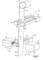
- the apparatus 36 comprises a retaining device 40 for receiving and clamping end 13A of the sealing strip 13.
- the retaining device 40 can be opened to receive the sealing strip 13 section and then closed to clamp the section in position, as shown in Figure 7.
- a bonding block 38 is provided which faces the end 13A of the sealing strip that emerges from the retaining device 40.
- the retaining device 40 and bonding block 38 are mounted on slides or similar mechanisms (not shown) so as to be slidable in the directions of the arrows A and B to bring the ends of the clamped sealing profile sections 38,40 towards and away from bonding block 38.
- a roll 42 of foil 15 is mounted above the retaining device 40 and bonding block 38 by supporting means (not shown).
- a heater 48 is positionable between the foil 15 and the strip section mounted in retaining device 40.
- the heater 48 is mounted on a transporting unit 54, the transporting unit 54 being movable to and fro in the direction of arrows C and D so that the heater 28 can be moved in the direction C into the position shown in Figure 7 and moved in the direction of arrow D so that it clears the space between the retaining device 40 and the bonding block 38.
- the foil 15 may be a thermoplastic foil or film, and for example may be made from a polyolefin material or other suitable thermoplastic material.
- the perforating unit 60 carries two punch support members 62,64, each shaped similarly to heater 48 and respectively carrying one or more punches 66 and one or more recesses 68 ( Figure 8).
- the end 13A of the strip which is to have the foil 15 bonded thereto is clamped in the retaining device 40 so that the end 13A protrudes from the retaining device 40 towards the bonding block 38.
- a length of foil 15 is unwound from the roll 42, generally into the position shown in Figure 7, where it passes between the punch support members 62,64 and the bonding block 38 and retaining unit 40.
- the punch support members 62,64 are then moved towards each other in the direction of arrows E,F to punch one or more slits, holes or apertures in the foil 15.
- the punch support members 62,64 are then moved apart again (into the spaced apart position shown in Figure 7) so as to be clear of the foil 15.
- a slit 70 formed by the punch 66 is shown in Figure 7.
- the slit 70 moves into the region between the bonding block 38 and the retaining unit 40.
- the transporting unit 54 is moved in the direction of arrow C so as to bring the heater 48 into the position shown in Figure 7.
- the heater is then activated.
- the heater 48 causes heating of the end of the profile section 13A and the foil 15 (at this stage the slit 70 being in a position corresponding to the hollow chamber of the sealing part 23 of the end 13A of the sealing strip 13).
- the transporting unit 54 is then withdrawn in the direction of arrow D so that the heater 48 is clear of the space between the retaining device 40 and the bonding block 38.
- the retaining device 40 (and/or the bonding block 38) is/are then moved towards each other so as to bring the end 13A of the strip 13 into contact with the side 33 of the foil 15 with a predetermined amount of pressure.
- the heated foil 15 thus thermally bonds to the end 13A of the sealing profile 13.
- the retaining device 40 and the bonding block 38 are then moved apart.
- the foil 15 is cut along its length above and below the sealing portion 13 in order to allow the part of the foil now attached to the sealing strip 13 to be separated from the remainder of the foil attached to the roll 42.
- the sealing strip 13 (with a portion of the foil 15 attached thereto) can then be removed from the retaining unit 40.
- the excess foil material can then be cut away around the periphery of the sealing strip 13 so that there is only foil 15 present over the end face of the strip 13.
- the foil 15 on the roll 42 may be plain foil, without any slits or holes or other apertures therein, these being formed immediately prior to the bonding operation by the punch 66 and the movement of the punch support members 62,64.
- the punching action to form the slits, holes or other apertures in the foil 15, could take place before or after the heating action, although it preferably takes place before the heating action, as described above.
- the holes or other apertures are formed in the foil 15 by a mechanical punching operation.
- the holes or other apertures could be formed by other suitable nonmechanical means, such as by a jet of air or gas or by an electrical spark arrangement.
- the thus formed sealing strip 13 with the foil 15 attached to end 13A thereof can then be supplied for fitting to a boot/trunk opening 1.
- the presence of the foil 15 facilitates a bonding of the end 13B of the sealing strip to the end 13A of the sealing strip when the sealing strip 13 is fitted around the hinge arms 27 or other obstructions.
- sealing strip 13 When the sealing strip 13 is formed into a loop, it will have a similar appearance to a known loop sealing strip shown in Figures 2 and 3.
- the through slit or slits 70 provided in the foil 15 in the region of the hollow chambe r 23 enables, in the finished joint, air to pass from one side of the foil 15 to the other as shown by arrows X and Y in Figure 3. Therefore, the slits 70 prevent a build up of pressure across the foil 15 in the event of compression of the strip 13. Such compression may take place during fitting of the strips onto the vehicle body and/or in use when the strip 13 is compressed by the closing boot/trunk lid 29. Any such build up in pressure could tend to cause bursting of the foil 15 and rupture of the joint. The slits reduce this risk by allowing air to pass from one side of the foil 15 to the other.
- the slit or slits 70 could be replaced by slots or other holes, apertures or cut outs.
- the foil could be rendered air or gas permeable in some other way.
- Figures 9,10 and 11 show a first embodiment of a tool 80 suitable for bonding the ends 13A and 13B of the strip 13 together with the strip is positioned in situ in the boot opening and threaded behind the hinge arms 27.
- the apparatus disclosed in EP1284852 is not suitable for performing such an operation because: (1) that apparatus is for bonding a foil simultaneously to both ends of the sealing strip, and (2) that apparatus is not portable and cannot be used on a sealing strip that is treaded behind the hinge arms 27.
- the tool 80 is sized such that its base 82 can pass through the boot/trunk opening 1 in the vehicle body 3 and rest on the floor of that opening 1.
- the base 82 accommodates a power supply 83 for powering a heater 84.
- a C-shaped opening is formed in the sidewalls 86 of the tool 80.
- a first mounting plate 88 extends between the sidewalls at the base of the C-shaped opening and a second mounting plate 90 extends between the sidewalls at the top of the C-shaped opening.
- the second mounting plate 90 has a hole formed therethrough through which the heating end 92 of the heater 84 extends.
- On the first mounting plate 88 two retaining devices 94,96 are provided. These retaining devices are of similar configuration to the retaining device 40 described with reference to Figure 7.
- the retaining device 94 includes a first section 98 and a second section 100 pivotally attached thereto at hinge 102.
- the end 13A of the sealing strip 13 (with the foil 15 bonded thereto) is positioned in an appropriately-shaped recess in the first section 98 so that the end 13A protrudes slightly from the first section 98, as best seen in Figure 11.
- the second section 100 (also having an appropriately-shaped recess) is then lowered onto the first section 98 to clamp the end 13A of the sealing strip 13 in position, using the handle 104.
- the second retaining device 96 has a similar configuration to the first retaining device 98, with like elements being designated with the same reference numeral.
- the opposite end 13B of the sealing strip 13 is mounted in the second retaining device 96 in a similar manner to the manner in which the end 13A is mounted in the first retaining device 94.
- the second retaining device 96 differs from the first retaining device 94 in that it is mounted to the first mounting plate so as to be slidably movable in the direction of arrows G and H ( Figure 11).
- the heating end 92 of the heater 84 is slid in the direction of arrow I into the position shown in Figures 10 and 11 so that it lies between the ends 13A and 13B.
- the heating device 84 then generates hot air which is emitted from outlets in the heating end 92 and heats the ends 13A and 13B of the strip 13 and the foil 15 attached to end 13A.
- the heating end 92 is then slid in the direction of arrow J so as to be clear of the space between the retaining devices 94 and 96.
- the second retaining device 96 is then slid in the direction of arrow G in order to bring the end 13B of the seal 13 into pressurised contact with the foil 15 mounted on the end 13A of the sealing strip 13.
- the first sections 100 of the retaining devices 94,96 can then be opened (to the position shown in Figure 10) and the sealing strip 13 (now formed in a continuous loop) can be removed from the tool 80.
- the tool 80 can then be removed from the boot/trunk opening 1.
- the heating function is automatically activated.
- the heating end 92 is moved away from the space between the retaining devices 94,96, it is automatically deactivated.
- the thus formed looped strip 13 can then be fitted to the flange 5 by any suitable means.
- the sealing strip 13 may have the general form described in GB 2212844 , where the sidewalls of the channel are splayed apart so as to enlarge the mouth of the channel and easing its application onto the mounting flange.
- the sealing strip 13 can then be securely fitted to the flange 5 by using a suitable tool for pressing the sidewalls of the channel together, such as a tool disclosed in EP 1115589 or EP 0497048 .
- a suitable tool for pressing the sidewalls of the channel together such as a tool disclosed in EP 1115589 or EP 0497048 .
- such tools are not suitable for fitting a strip to a flange in the region of an obstruction such as hinge arms 27.
- the sealing strip may be securely fitted to the flange 5 using the tool disclosed in our co-pending patent application No. GB 0514295.5 entitled "Fitting of Flexible Strips" filed on 12th July 2005.
- the heating end 92 of the heater 84 may provide heat other that by emission of hot air.
- a heating element which generates radiant heat may be used.
- Figures 12,13 and 14 show a second embodiment of apparatus 110 for joining the opposite ends 13A,13B of the strip 13 when it is positioned in situ in the region of the boot opening 1 and mounted around the hinges arms 27.
- the apparatus comprises a C-shaped frame 112.
- the lower limb 114 of the frame 112 lies generally parallel to the ground 113 in use and has wheels or rollers 115 fitted thereto to allow the frame 112 to roll along the ground 113.
- the lower limb 114 of the frame 112 is configured so as to be slidable in the space between the ground 113 and the underside of the vehicle body 3.
- the upper limb 116 of the frame 112 extends generally parallel to the lower limb 114 and is spaced apart therefrom by connecting limb 118.
- the upper limb 116 is sized and configured to enter the boot/trunk opening 1.
- On the upper surface of the upper limb 116 is carried a sealing strip joining device 120.
- the frame 112 is moved along the ground 113 in order to bring the joining device 120 into a position in the boot/trunk opening 1. This enables the ends 13A and 13B of a seal 13 positioned so that it is threaded behind the hinge arms 27 to be bonded together to form a continuous sealing loop in situ.
- the joining device comprises first and second strip retaining devices 122, 124.
- a first section 126 of the first retaining device 122 is fixed to the upper limb 116.
- a second section 128 is pivotally attached to the first section 126 in order to allow the sections 128,126 to be separated and the end 13A of the seal (with the foil 15 attached thereto) to be mounted securely in a recess in the retaining device 122.
- the second retaining device 124 has similarly configured first and second sections 126,128 for clamping the opposite end 13B of the sealing strip 13.
- the first section 126 of the second retaining device 124 is slidable in the direction of arrows K and L ( Figure 13).
- the handles 130, 132 of the respective retaining devices 122,124 allow the retaining devices 122,124 to be opened and closed. Further the handle 132 of the second retaining device 124 provides for rotation of mounting bar 134 to which heating elements 136 are mounted.
- the handle 132 When the ends 13A and 13B of the sealing strip 13 are mounted in the retaining devices 122 and 124, the handle 132 is rotated in order to cause corresponding rotation of the mounting bar 134. This brings the heating elements 136 into a position between the opposite ends 13A and 13B of the sealing strip and heats those ends. The heating elements 136 are then pivoted away from the gap between the retaining devices 122 and 124 (into the position shown in Figure 13), whereafter the second retaining device 124 is slid towards the first retaining device 122 in order to bring the end 13B of the sealing strip 13 into contact with the foil 15 attached to the end 13A of the sealing strip 13.
- the now bonded ends 13A,13B of the sealing strip are removed from the retaining devices 122,124.
- the thus formed looped sealing strip 13 can then be mounted to the flange 5 of the boot/trunk opening 1. Tools of the type referred to above can be used to fit the sealing strip 13 to the flange 5 in the manner described above.
- the foil 15 used in any of the embodiments may be of any suitable type for ensuring an effective bond, taking into account the material and characteristics of the sealing profile 13. It may, for example, have a melting point of between 120 and 130°C.
- the apparatus and method described can provide a very quick curing joint (in four to five seconds) and which is immediately capable of withstanding loads. The need for vulcanisation is avoided.
- the embodiments described have referred to the fitting of sealing strips to the opening 1 of a boot/trunk of a motor vehicle 3, it should be appreciated that the invention is also applicable to the fitting of sealing strips around other openings, such as door openings.
- the hinges that attach the door to a door frame of a vehicle may provide an obstruction in the door opening similar to the hinge arms 27 of the boot opening 1 described above.
Landscapes
- Engineering & Computer Science (AREA)
- Mechanical Engineering (AREA)
- Chemical & Material Sciences (AREA)
- Combustion & Propulsion (AREA)
- Lining Or Joining Of Plastics Or The Like (AREA)
Abstract
Description
- The present invention relates to a sealing, trimming or guiding strip, apparatus for forming such a strip, apparatus for bonding together the opposite ends of such a strip to form a loop-like strip, and corresponding methods. The strips are particularly, though not exclusively, for use on motor vehicle bodies such as the sealing around a boot or trunk or other closable opening of a vehicle.
- It is known to provide pre-formed loop-shaped sealing strips for fitment around closable openings of a vehicle such as around a boot or trunk opening). These can be fitted relatively simply to a flange around the opening when the boot/trunk lid is not fitted to the vehicle body (such as during manufacture of the vehicle). However, after manufacture of the vehicle such sealing strips cannot be fitted satisfactorily because the hinge arms that attach the boot/trunk lid to the vehicle body form an obstruction. The known solution of providing a length of sealing strip and fitting this around the flange of the opening and leaving the opposite ends of the length of strip abutting or adjacent is unsatisfactory because this reduces the effectiveness of the seal and provides an unattractive appearance.
- According to a first aspect of the invention, there is provided a sealing, trimming or guiding strip having an end face with one surface of a heat-bonding sheet of material bonded to said end face, the other surface of the sheet being unbonded and available for subsequent bonding to another end face.
- According to a second aspect of the invention, there is provided apparatus for forming a sealing, trimming or guiding strip with a heat-bonding sheet of material at an end face thereof, the apparatus including clamping means for positioning the strip, means for providing the sheet of material in the region of the end face, means for heating the end face of the strip and/or the sheet of material, and means for pressing the sheet of material against the end face of the strip, such that the strip is formed with the sheet of material bonded to one end face only thereof.
- According to a third aspect of the invention, there is provided a method for forming a sealing, trimming or guiding strip with a heat-bonding sheet of material at an end face thereof, the method including clamping the strip in position, providing the sheet of material in the region of the end face of the strip, heating the end face of the strip and/or the sheet of material, and pressing the sheet of material against the end face of the strip, such that the strip is formed with the sheet of material bonded to one end face only thereof.
- According to a fourth aspect of the invention, there is provided apparatus for forming a looped sealing, trimming or guiding strip from a length of strip having first and second ends, the first end having an end face with a heat-bonding sheet of material bonded to that end face, the apparatus including means for positioning the first and second ends of the strip so that the end faces thereof are generally aligned, means for applying heat to at least one of the respective end faces and/or the sheet of material, and means for pressing the first and second ends of the strip together such that the sheet of material bonds the ends of the strips together, thereby forming said loop.
- According to a fifth aspect of the invention, there is provided method of sealing around an opening in a motor vehicle body having an obstruction in the region of the opening, the method including providing a sealing strip having first and second ends, the first end having an end face with a heat bonding sheet of material bonded to that end face, positioning the strip around the obstruction, bonding the first end of the strip to the second end of the strip using the sheet of material by applying heat thereto, and mounting the thus formed looped strip to a mount around the periphery of the opening.
- A sealing, trimming or guiding strip embodying the invention, a tool and method for forming such a strip embodying the invention, and apparatus and methods for providing in situ forming of a loop-shaped sealing strip, will now be described, by way of example, with reference to the accompanying diagrammatic drawings in which:-
- Figure 1 is an overhead plan view of the boot/trunk opening of the vehicle body;
- Figure 2 is an overhead plan view of a pre-formed loop-shaped sealing strip of known configuration;
- Figure 3 is a detailed view of the strip of Figure 2;
- Figure 4 is a cut-away view of the sealing strip of Figures 2 and 3;
- Figure 5 is a partial perspective view of a boot/trunk lid and boot/trunk lid opening of a motor vehicle;
- Figure 6 is a view of part of a sealing strip in accordance with an embodiment of the invention;
- Figure 7 is a perspective view of one form of apparatus for forming the seal of Figure 6;
- Figure 8 is a scrap plan view of part of the apparatus of Figure 7;
- Figure 9 is a perspective view of a first embodiment of apparatus for forming a loop-shaped strip in situ;
- Figure 10 is a close-up view of part of the apparatus of Figure 9;
- Figure 11 is a scrap plan view of part of the apparatus of Figures 9 and 10;
- Figure 12 is a front elevational view of apparatus of a second embodiment of the invention for forming a loop-shaped seal in situ;
- Figure 13 is an enlarged view of part of the apparatus of Figure 12; and
- Figure 14 is a side elevational view of the apparatus of Figures 12 and 13 and a motor vehicle body.
- In the Figures like elements are generally designated with the same reference numerals.
- Figure 1 shows an overhead plan view of the boot/trunk opening 1 in a
motor vehicle body 3. Around the opening a mount orflange 5 is formed where anouter body panel 7 and aninner body panel 9 meet. Thesebody panels flange 5 by adhesive, spot welding or any other suitable technique. Theinner panel 9 is formed from the same sheet of material that forms therear wings 11 of themotor vehicle 3. - A boot/trunk lid is mounted on the
vehicle body 3 for closing theopening 1 in the conventional manner. In order to provide a weather tight seal for theopening 1, a sealing strip 13 (Figure 2) is mounted over theflange 5 and extends therearound to form a loop. - In order to provide a
sealing strip 13 that is in the form of a loop, it is known to form a length of sealing strip to the desired length and to join theopposite ends film 15. A sealing strip having such an arrangement and an apparatus for joining the opposite ends of the sealing strip is disclosed inEP 1284852 . - Figure 3 shows a partial view of the
sealing strip 13. Thesealing strip 13 comprises extruded plastics or rubber or similar material defining achannel 17 which, in use, embracingly grips theflange 5. The extruded material preferably definesintegral gripping lips 19 extending across the interior of thechannel 17 from opposite facing sidewalls thereof, theselips 19 frictionally contacting theflange 5 in use to help secure thestrip 13 in position thereon. The extruded material defining thechannel 17 may be reinforced by a channel-shaped embedded resilient core orcarrier 21 such as made of metal or other suitable rigid material. Thesealing strip 13 carries a relativelysoft sealing part 23 having a hollow chamber extending from the outside of the base and one sidewall of thechannel 17. When thesealing strip 13 is mounted on theflange 5, this sealingpart 23 is positioned so as to be partially compressed by the closing boot/trunk lid, thus providing a weather seal around theopening 1. A so-called "cosmetic lip" 25 may extend over the outside of the opposite sidewall of the channel 8 for receiving and hiding the edge of a trim panel, although typically such acosmetic lip 25 will not be provided for a boot/trunk seal (although will typically be provided for a door seal). - Figure 3 shows in more detail the region of the
sealing strip 13 where thefoil 15 joins theopposite ends - According to a known assembling arrangement, seals in the form of loops as shown in Figure 2 are supplied to vehicle manufacturers for fitting to
flanges 5 around boot/trunk openings 1 during the manufacture of vehicles. - It is advantageous to join the
opposite ends seal 13 byfoil 15, in contrast to an arrangement where the ends are not joined but simply abut one another or lie adjacent to one another, because this provides a more effective weather seal and an improved appearance. - A problem with this known arrangement arises when it is desired to fit a
sealing strip 13 to a boot/trunk opening 1 after the boot lid is fitted to thevehicle body 3. This will be explained in more detail with reference to the perspective view of the rear of thevehicle body 3 in Figure 5. A pre-formed loopedseal 13 cannot be fitted to theflange 5 surrounding theopening 1 when there is an obstruction around the periphery of theopening 1. Such an obstruction might comprise, for example, thehinge arms 27 that attach the boot/trunk lid 29 to thevehicle body 3 and allow angular movement of the boot/trunk lid 29 with respect to thebody 3 in order that the boot/trunk opening 1 can be opened and closed. - The
hinge arms 27 may be mounted to the boot/trunk lid 29 by bolts or welding and are coupled to thevehicle body 3 by a hinge arrangement (not shown) that allows rotational movement of the boot-trunk lid 29 and hingearms 27 in the direction ofarrows 31. - One arrangement for fitting a
seal 13 to the opening shown in Figure 5 would be to supply theseal 13 as a length of sealing strip where the opposite ends are not joined together (i.e. in un-looped form). Thesealing strip 13 can then be threaded behind thehinge arms 27 and fitted to theflange 5. Theopposite ends strip 13 will then abut or lie adjacent to one another at some point around theopening 1. As explained above, this is unsatisfactory as it reduces the effectiveness of the weather seal and results in an unattractive visible join or gap between theopposite ends strip 13. - Another potential way of fitting a looped sealing strip in such a situation would be to stretch the sealing strip so that it fits over the boot/
trunk lid 29 so that it could subsequently be fitted to theflange 5 despite the presence ofhinge arms 27. However, this is generally impracticable. Firstly, there may be other obstructions, such as a hydraulic ram between the boot/trunk lid 29 and theflange 5 which prevent thesealing strip 13 from being fitted to theflange 5. Secondly, even if it is possible to stretch thesealing strip 13 sufficiently to fit it over the boot/trunk lid 29, this is likely to damage the sealing strip and/or break the bond between the ends of the sealing strip and thefoil 15. Thirdly, most sealing strips are designed so that they are not stretchable in this manner, and typically include a rigid metal carrier which prevents such stretching. - In accordance with an important feature of the embodiments of the invention, a sealing strip arrangement is provided that has a
foil 15 bonded initially to oneend 13A (only) thereof. Theother end 13B of thestrip 13 does not have the foil attached thereto and is available for subsequent bonding to theend 13A having thefoil 15 bonded thereto. Figure 6 shows a view of part of such astrip 13 in accordance with the embodiment of the invention. Afirst surface 33 of thefoil 15 is bonded to the face of theend 13A of thestrip 13. Theopposite surface 35 of thefoil 15 is exposed. Such lengths of sealing strip 13 (with the ends unbonded to one another) can be supplied for fitment to boot/trunk openings 1. The configuration of the strip may be as shown in Figure 4. The length of the sealingstrip 13 can be threaded behind thehinge arms 27. Theend 13A of the sealingstrip 13 to which thefoil 15 is attached can then be bonded, using the foil, to theother end 13B of the sealing strip (where no foil is present). This bonding of the opposite ends 13A, 13B of thestrip 13 is performed in situ in theboot opening 1 or by a tool brought to the vicinity of theboot opening 1 in order that the opposite ends 13A, 13B can be bonded together whilst the strip is fitted between thehinge arms 27 and thevehicle body 3. Methods and tools for performing such a bonding operation will be described later. - There will now be described, with reference to Figures 7 and 8 an apparatus for forming a sealing strip with a
foil 15 at one end thereof as shown in Figure 6. Theapparatus 36 comprises a retainingdevice 40 for receiving and clampingend 13A of the sealingstrip 13. The retainingdevice 40 can be opened to receive the sealingstrip 13 section and then closed to clamp the section in position, as shown in Figure 7. Abonding block 38 is provided which faces theend 13A of the sealing strip that emerges from the retainingdevice 40. The retainingdevice 40 andbonding block 38 are mounted on slides or similar mechanisms (not shown) so as to be slidable in the directions of the arrows A and B to bring the ends of the clamped sealingprofile sections block 38. Aroll 42 offoil 15 is mounted above the retainingdevice 40 andbonding block 38 by supporting means (not shown). - A heater 48 is positionable between the
foil 15 and the strip section mounted in retainingdevice 40. The heater 48 is mounted on a transportingunit 54, the transportingunit 54 being movable to and fro in the direction of arrows C and D so that the heater 28 can be moved in the direction C into the position shown in Figure 7 and moved in the direction of arrow D so that it clears the space between the retainingdevice 40 and thebonding block 38. - The
foil 15 may be a thermoplastic foil or film, and for example may be made from a polyolefin material or other suitable thermoplastic material. - Between the
roll 42, and the retainingdevices unit 60. The perforatingunit 60 carries twopunch support members more punches 66 and one or more recesses 68 (Figure 8). - To form the sealing strip of Figure 6, the
end 13A of the strip which is to have thefoil 15 bonded thereto, is clamped in the retainingdevice 40 so that theend 13A protrudes from the retainingdevice 40 towards thebonding block 38. A length offoil 15 is unwound from theroll 42, generally into the position shown in Figure 7, where it passes between thepunch support members bonding block 38 and retainingunit 40. Thepunch support members foil 15. Thepunch support members foil 15. A slit 70 formed by thepunch 66 is shown in Figure 7. As thefoil 15 is unwound from theroll 42, theslit 70 moves into the region between thebonding block 38 and the retainingunit 40. The transportingunit 54 is moved in the direction of arrow C so as to bring the heater 48 into the position shown in Figure 7. The heater is then activated. The heater 48 causes heating of the end of theprofile section 13A and the foil 15 (at this stage theslit 70 being in a position corresponding to the hollow chamber of the sealingpart 23 of theend 13A of the sealing strip 13). - The transporting
unit 54 is then withdrawn in the direction of arrow D so that the heater 48 is clear of the space between the retainingdevice 40 and thebonding block 38. The retaining device 40 (and/or the bonding block 38) is/are then moved towards each other so as to bring theend 13A of thestrip 13 into contact with theside 33 of thefoil 15 with a predetermined amount of pressure. Theheated foil 15 thus thermally bonds to theend 13A of the sealingprofile 13. The retainingdevice 40 and thebonding block 38 are then moved apart. Thefoil 15 is cut along its length above and below the sealingportion 13 in order to allow the part of the foil now attached to the sealingstrip 13 to be separated from the remainder of the foil attached to theroll 42. The sealing strip 13 (with a portion of thefoil 15 attached thereto) can then be removed from the retainingunit 40. The excess foil material can then be cut away around the periphery of the sealingstrip 13 so that there isonly foil 15 present over the end face of thestrip 13. - The
foil 15 on theroll 42 may be plain foil, without any slits or holes or other apertures therein, these being formed immediately prior to the bonding operation by thepunch 66 and the movement of thepunch support members - Clearly, there can be more than one
punch 66 and onematching recess 68, so as to produce a required plurality of slits, holes or other apertures. - The punching action, to form the slits, holes or other apertures in the
foil 15, could take place before or after the heating action, although it preferably takes place before the heating action, as described above. - As described with reference to Figures 7 and 8, the holes or other apertures are formed in the
foil 15 by a mechanical punching operation. Instead, however, the holes or other apertures could be formed by other suitable nonmechanical means, such as by a jet of air or gas or by an electrical spark arrangement. - The thus formed sealing
strip 13 with thefoil 15 attached to end 13A thereof can then be supplied for fitting to a boot/trunk opening 1. As mentioned above, the presence of thefoil 15 facilitates a bonding of theend 13B of the sealing strip to theend 13A of the sealing strip when the sealingstrip 13 is fitted around thehinge arms 27 or other obstructions. - When the sealing
strip 13 is formed into a loop, it will have a similar appearance to a known loop sealing strip shown in Figures 2 and 3. - The through slit or slits 70 provided in the
foil 15 in the region of thehollow chambe r 23 enables, in the finished joint, air to pass from one side of thefoil 15 to the other as shown by arrows X and Y in Figure 3. Therefore, theslits 70 prevent a build up of pressure across thefoil 15 in the event of compression of thestrip 13. Such compression may take place during fitting of the strips onto the vehicle body and/or in use when thestrip 13 is compressed by the closing boot/trunk lid 29. Any such build up in pressure could tend to cause bursting of thefoil 15 and rupture of the joint. The slits reduce this risk by allowing air to pass from one side of thefoil 15 to the other. - It will be appreciated that the slit or slits 70 could be replaced by slots or other holes, apertures or cut outs. Instead, the foil could be rendered air or gas permeable in some other way.
- Figures 9,10 and 11 show a first embodiment of a
tool 80 suitable for bonding theends strip 13 together with the strip is positioned in situ in the boot opening and threaded behind thehinge arms 27. It will be appreciated that the apparatus disclosed inEP1284852 is not suitable for performing such an operation because: (1) that apparatus is for bonding a foil simultaneously to both ends of the sealing strip, and (2) that apparatus is not portable and cannot be used on a sealing strip that is treaded behind thehinge arms 27. - The
tool 80 is sized such that itsbase 82 can pass through the boot/trunk opening 1 in thevehicle body 3 and rest on the floor of thatopening 1. Thebase 82 accommodates apower supply 83 for powering aheater 84. Above the base 82 a C-shaped opening is formed in thesidewalls 86 of thetool 80. A first mountingplate 88 extends between the sidewalls at the base of the C-shaped opening and a second mountingplate 90 extends between the sidewalls at the top of the C-shaped opening. Thesecond mounting plate 90 has a hole formed therethrough through which theheating end 92 of theheater 84 extends. On the first mountingplate 88 tworetaining devices device 40 described with reference to Figure 7. - As can be seen in more detail in Figure 10, the retaining
device 94 includes afirst section 98 and asecond section 100 pivotally attached thereto athinge 102. Theend 13A of the sealing strip 13 (with thefoil 15 bonded thereto) is positioned in an appropriately-shaped recess in thefirst section 98 so that theend 13A protrudes slightly from thefirst section 98, as best seen in Figure 11. The second section 100 (also having an appropriately-shaped recess) is then lowered onto thefirst section 98 to clamp theend 13A of the sealingstrip 13 in position, using thehandle 104. Thesecond retaining device 96 has a similar configuration to thefirst retaining device 98, with like elements being designated with the same reference numeral. Theopposite end 13B of the sealingstrip 13 is mounted in thesecond retaining device 96 in a similar manner to the manner in which theend 13A is mounted in thefirst retaining device 94. However, thesecond retaining device 96 differs from thefirst retaining device 94 in that it is mounted to the first mounting plate so as to be slidably movable in the direction of arrows G and H (Figure 11). - With the
ends strip 13 clamped inrespective retaining devices heating end 92 of theheater 84 is slid in the direction of arrow I into the position shown in Figures 10 and 11 so that it lies between theends heating device 84 then generates hot air which is emitted from outlets in theheating end 92 and heats theends strip 13 and thefoil 15 attached to end 13A. Theheating end 92 is then slid in the direction of arrow J so as to be clear of the space between the retainingdevices second retaining device 96 is then slid in the direction of arrow G in order to bring theend 13B of theseal 13 into pressurised contact with thefoil 15 mounted on theend 13A of the sealingstrip 13. Thefirst sections 100 of the retainingdevices tool 80. Thetool 80 can then be removed from the boot/trunk opening 1. - Advantageously, when the
heating end 92 is moved into position between the retainingdevices heating end 92 is moved away from the space between the retainingdevices - The thus formed looped
strip 13 can then be fitted to theflange 5 by any suitable means. - The sealing
strip 13 may have the general form described inGB 2212844 - The sealing
strip 13 can then be securely fitted to theflange 5 by using a suitable tool for pressing the sidewalls of the channel together, such as a tool disclosed inEP 1115589 orEP 0497048 . However, it should be noted that such tools are not suitable for fitting a strip to a flange in the region of an obstruction such ashinge arms 27. In the region of the hinge arms, the sealing strip may be securely fitted to theflange 5 using the tool disclosed in our co-pending patent application No.GB 0514295.5 - The
heating end 92 of theheater 84 may provide heat other that by emission of hot air. For example, a heating element which generates radiant heat may be used. - Figures 12,13 and 14 show a second embodiment of
apparatus 110 for joining the opposite ends 13A,13B of thestrip 13 when it is positioned in situ in the region of theboot opening 1 and mounted around thehinges arms 27. As best seen in Figure 14, the apparatus comprises a C-shapedframe 112. Thelower limb 114 of theframe 112 lies generally parallel to theground 113 in use and has wheels orrollers 115 fitted thereto to allow theframe 112 to roll along theground 113. Thelower limb 114 of theframe 112 is configured so as to be slidable in the space between theground 113 and the underside of thevehicle body 3. Theupper limb 116 of theframe 112 extends generally parallel to thelower limb 114 and is spaced apart therefrom by connectinglimb 118. Theupper limb 116 is sized and configured to enter the boot/trunk opening 1. On the upper surface of theupper limb 116 is carried a sealingstrip joining device 120. Conveniently, theframe 112 is moved along theground 113 in order to bring the joiningdevice 120 into a position in the boot/trunk opening 1. This enables theends seal 13 positioned so that it is threaded behind thehinge arms 27 to be bonded together to form a continuous sealing loop in situ. - The joining device comprises first and second
strip retaining devices first section 126 of thefirst retaining device 122 is fixed to theupper limb 116. Asecond section 128 is pivotally attached to thefirst section 126 in order to allow the sections 128,126 to be separated and theend 13A of the seal (with thefoil 15 attached thereto) to be mounted securely in a recess in theretaining device 122. Thesecond retaining device 124 has similarly configured first and second sections 126,128 for clamping theopposite end 13B of the sealingstrip 13. However, thefirst section 126 of thesecond retaining device 124 is slidable in the direction of arrows K and L (Figure 13). Thehandles handle 132 of thesecond retaining device 124 provides for rotation of mountingbar 134 to whichheating elements 136 are mounted. - When the ends 13A and 13B of the sealing
strip 13 are mounted in the retainingdevices handle 132 is rotated in order to cause corresponding rotation of the mountingbar 134. This brings theheating elements 136 into a position between the opposite ends 13A and 13B of the sealing strip and heats those ends. Theheating elements 136 are then pivoted away from the gap between the retainingdevices 122 and 124 (into the position shown in Figure 13), whereafter thesecond retaining device 124 is slid towards thefirst retaining device 122 in order to bring theend 13B of the sealingstrip 13 into contact with thefoil 15 attached to theend 13A of the sealingstrip 13. After a short time, the now bonded ends 13A,13B of the sealing strip are removed from the retaining devices 122,124. The thus formed looped sealingstrip 13 can then be mounted to theflange 5 of the boot/trunk opening 1. Tools of the type referred to above can be used to fit the sealingstrip 13 to theflange 5 in the manner described above. - The
foil 15 used in any of the embodiments may be of any suitable type for ensuring an effective bond, taking into account the material and characteristics of the sealingprofile 13. It may, for example, have a melting point of between 120 and 130°C. The apparatus and method described can provide a very quick curing joint (in four to five seconds) and which is immediately capable of withstanding loads. The need for vulcanisation is avoided. - Although the embodiments described have referred to the fitting of sealing strips to the
opening 1 of a boot/trunk of amotor vehicle 3, it should be appreciated that the invention is also applicable to the fitting of sealing strips around other openings, such as door openings. The hinges that attach the door to a door frame of a vehicle may provide an obstruction in the door opening similar to thehinge arms 27 of theboot opening 1 described above. - It should further be appreciated that, although the arrangements described above are particularly advantageous when it is not possible to supply and fit a pre-formed looped sealing strip (by virtue of the presence of obstructions such as
hinge arms 27 or other hinges), the apparatus and methods described could of course be used to fit a sealing strip around an opening and to form that sealing strip into a loop even when no obstruction is present.
Claims (40)
- Apparatus for forming a looped sealing, trimming or guiding strip from a length of strip (13) having first (13A) and second (13B) ends, the first end (13A) having an end face with a heat-bonding sheet of material (15) bonded to that end face, the apparatus including means (94,96) for positioning the first and second ends (13A,13B) of the strip (13) so that the end faces thereof are generally aligned, means (92) for applying heat to at least one of the respective end faces (13A,13B) and/or the sheet of material (15), and means for pressing the first and second ends (13A,13B) of the strip (13) together such that the sheet of material (15) bonds the ends of the strips together, thereby forming said loop.
- The apparatus of claim 1, wherein the apparatus is portable.
- The apparatus of claim 1 or 2, wherein the apparatus includes wheel or roller means (115) for allowing the apparatus to be positioned for allowing the loop to be formed in situ.
- The apparatus of claim 1, 2 or 3, wherein the apparatus has a weight that allows it to be lifted by a single person.
- The apparatus of any one of claims 1 to 4, wherein the heating means (92) comprises a hot air generator.
- The apparatus of any one of claims 1 to 5, wherein the heating means (92) is positionable between the sheet of material (15) and the second end (13A) of the strip for performing heating thereof.
- A method of sealing around an opening (1) in a motor vehicle body (3) having an obstruction (27) in the region of the opening (1), the method including providing a sealing strip (13) having first (13A) and second (13B) ends, the first end (13A) having an end face with a heat bonding sheet of material (15) bonded to that end face, positioning the strip (13) around the obstruction (27), bonding the first end (13A) of the strip to the second end (13B) of the strip using the sheet of material (15) by applying heat thereto, and mounting the thus formed looped strip to a mount (5) around the periphery of the opening (1).
- The method of claim 7, wherein the obstruction (27) comprises hinge means.
- The method of claim 8, wherein the opening (1) is a boot or trunk opening and the hinge means (27) comprises a hinge arm.
- The method of claim 8, wherein the opening is a door opening and the hinge means comprises a hinge.
- The method of claim 7, 8, 9 or 10, wherein the bonding step is performed after the closure member of the opening is mounted to the vehicle body.
- The method of claim 7, 8, 9, 10 or 11, wherein the bonding step is performed in the vicinity of the vehicle body.
- A sealing, trimming or guiding strip (13) having an end face (13A) with one surface (33) of a heat-bonding sheet of material (15) bonded to said end face (13A), the other surface (35) of the sheet being unbonded and available for subsequent bonding to another end face.
- The strip of claim 13, wherein said other end face is another end face (13B) of the said strip (13).
- The strip of claim 14, wherein the strip (13) is formable into a loop.
- The strip of claim 13,14 or 15, wherein said sheet (15) of material is air permeable.
- The strip of claim 13,14,15 or 16, wherein said sheet (15) of material has one or more perforations therein.
- The strip of claim 17, including a hollow chamber, and wherein said perforation allows the passage of air through said chamber.
- The strip of any one of claims 13 to 18, wherein the foil (15) comprises thermoplastic material.
- The strip of any one of claims 13 to 19, wherein the strip (13) includes a channel-shaped gripping or mounting section (17) for mounting the strip (13) to a mount or flange of a body, such as a vehicle body.
- The strip of any one of claims 13 to 20, including a relatively rigid reinforcement member or carrier (21) embedded in the strip (13).
- The strip of any one of claims 13 to 21, wherein the strip (13) is formed by extrusion.
- The strip of any one of claims 14 to 22, wherein the end faces (13A,13B) of the strip (13) are joined by the sheet of material (15) such that corresponding parts of the end faces are aligned with one another.
- The strip of claim 23, when dependent of claim 18, wherein the hollow chambers at the end faces are aligned with one another, the perforation allowing the passage of air between the respective hollow chambers.
- Apparatus for forming a sealing, trimming or guiding strip (13) with a heat-bonding sheet of material (15) at an end face (13A) thereof, the apparatus including clamping means (40) for positioning the strip (13), means (42) for providing the sheet of material in the region of the end face (13A), means (46) for heating the end face of the strip (13A) and/or the sheet of material (15), and means (38) for pressing the sheet of material (15) against the end face (13A) of the strip (13), such that the strip (13) is formed with the sheet of material (15) bonded to one end face (13A) only thereof.
- The apparatus of claim 25, wherein the heating means (46) is movable between a heating position in which it heats the sheet of material (15) and the end (13A) of the strip (13) and a second position which allows the pressing means (38) to press the sheet of material (15) against the end (13A) of the strip (13).
- The apparatus of claim 25 or 26, further including aperture-forming means (60,62,64,66) for forming one or more apertures (70) in the sheet of material (15) to allow the passage of air through the sheet of material (15).
- The apparatus of claim 27, wherein the aperture-forming means (60,62,64,66) is operable to form the aperture (70) in the sheet of material (15) prior to the part of the sheet of material having the aperture (70) being bonded to the end face (13A) of the strip (13).
- The apparatus of any one of claims 27 to 28, wherein the aperture-forming means (60,62,64,66) comprises mechanical punching means.
- The apparatus of any one of claims 27 to 29, including a reel from which the sheet of material (18) may be unwound into a position between the aperture-forming means and between the pressing means (38) and the end (13A) of the strip (13).
- The apparatus of any one of claims 25 to 30, wherein the sheet of material (15) is air-permeable.
- A method for forming a sealing, trimming or guiding strip (13) with a heat-bonding sheet of material (15) at an end face (13A) thereof, the method including clamping the strip (13) in position, providing the sheet of material (15) in the region of the end face (13A) of the strip (13), heating the end face (13A) of the strip (13) and/or the sheet of material (15), and pressing the sheet of material (15) against the end face (13A) of the strip (13), such that the strip (13) is formed with the sheet of material (15) bonded to one end face (13A) only thereof.
- The method of claim 32, including moving heating means (46) between a heating position in which it heats the sheet of material (15) and the end (13A) of the strip (13) and a second position which allows the sheet of material (15) to be pressed against the end (13A) of the strip (13).
- The method of claim 32 or 33, further including forming one or more apertures (70) in the sheet of material (15) to allow the passage of air through the sheet of material.
- The method of claim 34, wherein the aperture-forming step forms the aperture (70) in the sheet of material (15) prior to the part of the sheet of material (15) having the aperture (70) being bonded to the end face (13A) of the strip (13).
- The method of any one of claims 32 to 35, wherein the aperture (70) is formed by mechanical punching means (66).
- The method of any one of claims 32 to 36, wherein the sheet of material (15) is unwound from a reel (42) into a position where the aperture (70) is formed and then into a position where the sheet of material (15) is bonded to the end (13A) of the strip (13).
- The method of any one of claims 32 to 37, wherein the sheet of material (15) is air-permeable.
- The method of any one of claims 7 to 12, wherein the sealing strip is as claimed in any one of claims 13 to 24.
- The method of any one of claims 7 to 12, wherein the sealing strip is formed by the apparatus of any one of claims 25 to 30 or by the method of any one of claims 32 to 38.
Applications Claiming Priority (2)
| Application Number | Priority Date | Filing Date | Title |
|---|---|---|---|
| GB0514297A GB0514297D0 (en) | 2005-07-12 | 2005-07-12 | Bonding of sealing, trimming or guiding strips |
| GB0516890A GB2428215B (en) | 2005-07-12 | 2005-08-17 | Bonding of sealing, trimming or guiding strips |
Publications (2)
| Publication Number | Publication Date |
|---|---|
| EP1743758A2 true EP1743758A2 (en) | 2007-01-17 |
| EP1743758A3 EP1743758A3 (en) | 2008-02-13 |
Family
ID=37487559
Family Applications (1)
| Application Number | Title | Priority Date | Filing Date |
|---|---|---|---|
| EP20060253629 Withdrawn EP1743758A3 (en) | 2005-07-12 | 2006-07-11 | Bonding of sealing, trimming or guiding strips |
Country Status (1)
| Country | Link |
|---|---|
| EP (1) | EP1743758A3 (en) |
Cited By (5)
| Publication number | Priority date | Publication date | Assignee | Title |
|---|---|---|---|---|
| WO2011018131A1 (en) * | 2009-08-12 | 2011-02-17 | Thyssenkrupp Drauz Nothelfer Gmbh | Method for connecting the joint of profiled sealing elements and device for performing said method |
| EP2704894A4 (en) * | 2011-04-30 | 2016-01-27 | Michelin Rech Tech | METHODS AND APPARATUS FOR ASSEMBLING BEARING BANDS |
| CN106541579A (en) * | 2016-11-04 | 2017-03-29 | 海宁市盛祥线业有限公司 | A kind of sewing device of elastic processing |
| US9757916B2 (en) | 2011-06-30 | 2017-09-12 | Compagnie Generale Des Etablissements Michelin | Methods and apparatus for installing a tread ring upon a tire carcass |
| CN114851500A (en) * | 2022-07-04 | 2022-08-05 | 成都航利航空科技有限责任公司 | Automatic forming method and device for rubber sealing ring blank |
Family Cites Families (7)
| Publication number | Priority date | Publication date | Assignee | Title |
|---|---|---|---|---|
| US2793070A (en) * | 1953-11-16 | 1957-05-21 | Gen Motors Corp | Weatherstrip seal for automobile rear compartment |
| JPS5263279A (en) * | 1976-06-30 | 1977-05-25 | Tokyo Shibaura Electric Co | Method for manufacturing gasket |
| DE3906278A1 (en) * | 1989-02-28 | 1990-08-30 | Muetsch Adolf | Process and apparatus for bonding profiles |
| JPH07314560A (en) * | 1994-05-23 | 1995-12-05 | Nishikawa Rubber Co Ltd | Weather strip joining method and device |
| US6790498B2 (en) * | 2000-05-24 | 2004-09-14 | Gencorp Property, Inc. | Joined profile sections |
| GB2362601B (en) * | 2000-05-24 | 2004-04-21 | Draftex Ind Ltd | Apparatus for joining profile sections |
| WO2002053353A1 (en) * | 2001-01-04 | 2002-07-11 | Inno Vita Group Aktiebolag | Mobile device and method for the production of o-ring seals |
-
2006
- 2006-07-11 EP EP20060253629 patent/EP1743758A3/en not_active Withdrawn
Cited By (7)
| Publication number | Priority date | Publication date | Assignee | Title |
|---|---|---|---|---|
| WO2011018131A1 (en) * | 2009-08-12 | 2011-02-17 | Thyssenkrupp Drauz Nothelfer Gmbh | Method for connecting the joint of profiled sealing elements and device for performing said method |
| EP2704894A4 (en) * | 2011-04-30 | 2016-01-27 | Michelin Rech Tech | METHODS AND APPARATUS FOR ASSEMBLING BEARING BANDS |
| US9302439B2 (en) | 2011-04-30 | 2016-04-05 | Compagnie Generale Des Etablissements Michelin | Methods and apparatus for joining treads |
| US9757916B2 (en) | 2011-06-30 | 2017-09-12 | Compagnie Generale Des Etablissements Michelin | Methods and apparatus for installing a tread ring upon a tire carcass |
| US10843428B2 (en) | 2011-06-30 | 2020-11-24 | Compagnie Generale Des Etablissements Michelin | Methods and apparatus for installing a tread ring upon a tire carcass |
| CN106541579A (en) * | 2016-11-04 | 2017-03-29 | 海宁市盛祥线业有限公司 | A kind of sewing device of elastic processing |
| CN114851500A (en) * | 2022-07-04 | 2022-08-05 | 成都航利航空科技有限责任公司 | Automatic forming method and device for rubber sealing ring blank |
Also Published As
| Publication number | Publication date |
|---|---|
| EP1743758A3 (en) | 2008-02-13 |
Similar Documents
| Publication | Publication Date | Title |
|---|---|---|
| US20080211136A1 (en) | Method of making an automotive hardware carrier | |
| CA3011826A1 (en) | Infrared welded exterior panel assembly and process of making same | |
| JPH05124440A (en) | Strip for sealing or guidance | |
| US20080096003A1 (en) | Bonding of sealing, trimming or guiding strips | |
| US6948719B2 (en) | Extruded sealing section designed to be mounted on a projected part of a structure, pre-form of said section and procedure for mounting said pre-form onto the projecting part | |
| EP1743758A2 (en) | Bonding of sealing, trimming or guiding strips | |
| US6790498B2 (en) | Joined profile sections | |
| US10357952B2 (en) | Cutting tool guide structure and method of cutting adhesive-backed film applied to a surface of a vehicle | |
| JP2005532898A (en) | Masking strip | |
| GB2428215A (en) | Bonding sheet bonded to one end of strip | |
| JP2006501086A (en) | Sealing, trimming or guiding strip | |
| EP1284851B1 (en) | Apparatus for joining profile sections | |
| JP2009073441A (en) | Method of manufacturing trim material and device thereof | |
| WO1989005227A1 (en) | Method of manufacturing decorative sheet-carrying laminated molding | |
| US20050057078A1 (en) | Method of mounting a roof assembly into the interior of a vehicle; as well as such roof assembly and a vehicle | |
| JP4505737B2 (en) | Vehicle door trim | |
| JP2010162980A (en) | Vehicle body skeleton structure | |
| EP1572483B1 (en) | Method and apparatus of fixing of sealing and mounting strips to members | |
| US10792985B1 (en) | Drain apparatus for use with vehicle sunroofs | |
| GB2362602A (en) | Joining profile sections | |
| GB2435852A (en) | Bonding of sealing, trimming or guiding strips | |
| JPH11309730A (en) | Method for folding terminal of skin material | |
| WO2007102085A2 (en) | Bonding of sealing, trimming or guiding strips | |
| JPH11291356A (en) | Method for winding terminal of skin material | |
| JPH0378056B2 (en) |
Legal Events
| Date | Code | Title | Description |
|---|---|---|---|
| PUAI | Public reference made under article 153(3) epc to a published international application that has entered the european phase |
Free format text: ORIGINAL CODE: 0009012 |
|
| AK | Designated contracting states |
Kind code of ref document: A2 Designated state(s): AT BE BG CH CY CZ DE DK EE ES FI FR GB GR HU IE IS IT LI LT LU LV MC NL PL PT RO SE SI SK TR |
|
| AX | Request for extension of the european patent |
Extension state: AL BA HR MK YU |
|
| RIN1 | Information on inventor provided before grant (corrected) |
Inventor name: BLUM, ROCCO Inventor name: DRAGON, HORST |
|
| RAP1 | Party data changed (applicant data changed or rights of an application transferred) |
Owner name: AUDI AG Owner name: GDX NORTH AMERICA INC. |
|
| RIC1 | Information provided on ipc code assigned before grant |
Ipc: B60J 10/08 20060101ALI20070820BHEP Ipc: B29C 65/10 20060101ALI20070820BHEP Ipc: B29C 65/50 20060101ALI20070820BHEP Ipc: B29C 65/14 20060101ALI20070820BHEP Ipc: B29C 65/52 20060101AFI20061212BHEP |
|
| PUAL | Search report despatched |
Free format text: ORIGINAL CODE: 0009013 |
|
| AK | Designated contracting states |
Kind code of ref document: A3 Designated state(s): AT BE BG CH CY CZ DE DK EE ES FI FR GB GR HU IE IS IT LI LT LU LV MC NL PL PT RO SE SI SK TR |
|
| AX | Request for extension of the european patent |
Extension state: AL BA HR MK YU |
|
| RAP1 | Party data changed (applicant data changed or rights of an application transferred) |
Owner name: AUDI AG Owner name: GDX NORTH AMERICA INC. |
|
| AKX | Designation fees paid | ||
| REG | Reference to a national code |
Ref country code: DE Ref legal event code: 8566 |
|
| STAA | Information on the status of an ep patent application or granted ep patent |
Free format text: STATUS: THE APPLICATION IS DEEMED TO BE WITHDRAWN |
|
| 18D | Application deemed to be withdrawn |
Effective date: 20080814 |