EP0497048A1 - Apparatus and method for fitting a flexible strip - Google Patents
Apparatus and method for fitting a flexible strip Download PDFInfo
- Publication number
- EP0497048A1 EP0497048A1 EP91311296A EP91311296A EP0497048A1 EP 0497048 A1 EP0497048 A1 EP 0497048A1 EP 91311296 A EP91311296 A EP 91311296A EP 91311296 A EP91311296 A EP 91311296A EP 0497048 A1 EP0497048 A1 EP 0497048A1
- Authority
- EP
- European Patent Office
- Prior art keywords
- flange
- strip
- sealing strip
- curved path
- arrangement according
- Prior art date
- Legal status (The legal status is an assumption and is not a legal conclusion. Google has not performed a legal analysis and makes no representation as to the accuracy of the status listed.)
- Granted
Links
Images


Classifications
-
- B—PERFORMING OPERATIONS; TRANSPORTING
- B62—LAND VEHICLES FOR TRAVELLING OTHERWISE THAN ON RAILS
- B62D—MOTOR VEHICLES; TRAILERS
- B62D65/00—Designing, manufacturing, e.g. assembling, facilitating disassembly, or structurally modifying motor vehicles or trailers, not otherwise provided for
- B62D65/02—Joining sub-units or components to, or positioning sub-units or components with respect to, body shell or other sub-units or components
- B62D65/14—Joining sub-units or components to, or positioning sub-units or components with respect to, body shell or other sub-units or components the sub-units or components being passenger compartment fittings, e.g. seats, linings, trim, instrument panels
-
- B—PERFORMING OPERATIONS; TRANSPORTING
- B23—MACHINE TOOLS; METAL-WORKING NOT OTHERWISE PROVIDED FOR
- B23P—METAL-WORKING NOT OTHERWISE PROVIDED FOR; COMBINED OPERATIONS; UNIVERSAL MACHINE TOOLS
- B23P19/00—Machines for simply fitting together or separating metal parts or objects, or metal and non-metal parts, whether or not involving some deformation; Tools or devices therefor so far as not provided for in other classes
- B23P19/04—Machines for simply fitting together or separating metal parts or objects, or metal and non-metal parts, whether or not involving some deformation; Tools or devices therefor so far as not provided for in other classes for assembling or disassembling parts
- B23P19/047—Machines for simply fitting together or separating metal parts or objects, or metal and non-metal parts, whether or not involving some deformation; Tools or devices therefor so far as not provided for in other classes for assembling or disassembling parts for flexible profiles, e.g. sealing or decorating strips in grooves or on other profiles by devices moving along the flexible profile
-
- B—PERFORMING OPERATIONS; TRANSPORTING
- B60—VEHICLES IN GENERAL
- B60J—WINDOWS, WINDSCREENS, NON-FIXED ROOFS, DOORS, OR SIMILAR DEVICES FOR VEHICLES; REMOVABLE EXTERNAL PROTECTIVE COVERINGS SPECIALLY ADAPTED FOR VEHICLES
- B60J10/00—Sealing arrangements
- B60J10/45—Assembling sealing arrangements with vehicle parts
-
- Y—GENERAL TAGGING OF NEW TECHNOLOGICAL DEVELOPMENTS; GENERAL TAGGING OF CROSS-SECTIONAL TECHNOLOGIES SPANNING OVER SEVERAL SECTIONS OF THE IPC; TECHNICAL SUBJECTS COVERED BY FORMER USPC CROSS-REFERENCE ART COLLECTIONS [XRACs] AND DIGESTS
- Y10—TECHNICAL SUBJECTS COVERED BY FORMER USPC
- Y10T—TECHNICAL SUBJECTS COVERED BY FORMER US CLASSIFICATION
- Y10T29/00—Metal working
- Y10T29/53—Means to assemble or disassemble
- Y10T29/53039—Means to assemble or disassemble with control means energized in response to activator stimulated by condition sensor
-
- Y—GENERAL TAGGING OF NEW TECHNOLOGICAL DEVELOPMENTS; GENERAL TAGGING OF CROSS-SECTIONAL TECHNOLOGIES SPANNING OVER SEVERAL SECTIONS OF THE IPC; TECHNICAL SUBJECTS COVERED BY FORMER USPC CROSS-REFERENCE ART COLLECTIONS [XRACs] AND DIGESTS
- Y10—TECHNICAL SUBJECTS COVERED BY FORMER USPC
- Y10T—TECHNICAL SUBJECTS COVERED BY FORMER US CLASSIFICATION
- Y10T29/00—Metal working
- Y10T29/53—Means to assemble or disassemble
- Y10T29/53526—Running-length work
-
- Y—GENERAL TAGGING OF NEW TECHNOLOGICAL DEVELOPMENTS; GENERAL TAGGING OF CROSS-SECTIONAL TECHNOLOGIES SPANNING OVER SEVERAL SECTIONS OF THE IPC; TECHNICAL SUBJECTS COVERED BY FORMER USPC CROSS-REFERENCE ART COLLECTIONS [XRACs] AND DIGESTS
- Y10—TECHNICAL SUBJECTS COVERED BY FORMER USPC
- Y10T—TECHNICAL SUBJECTS COVERED BY FORMER US CLASSIFICATION
- Y10T29/00—Metal working
- Y10T29/53—Means to assemble or disassemble
- Y10T29/53657—Means to assemble or disassemble to apply or remove a resilient article [e.g., tube, sleeve, etc.]
Definitions
- the invention relates to robot arrangement for fitting a length of channel-shaped strip onto a mounting flange or the like, comprising mounting mean, means on the mounting means for supporting the sealing strip in a manner permitting it to be driven longitudinally, constraining means on the mounting means for constraining the strip to follow a predetermined curved path as it moves longitudinally so as to present the mouth of the channel facing outwardly of the curved path, and robot means for positioning the mounting means in juxtaposition with the flange so that the mouth of the channel of the strip at the distal end of the curved path embraces the flange, and strip-pressing means for pressing the strip onto the flange.
- Such an arrangement is shown in GB-A-2 227 779.
- This known arrangement is intended for fitting onto a mounting flange or the like a channel-shaped sealing strip of conventional type in which the side walls are substantially parallel with each other.
- a sealing strip normally incorporates a metal carrier or reinforcement intended to provide resilience to the strip so that it firmly grips the mounting flange.
- a problem can arise with the use of a sealing strip of this form: the action of pressing it onto the flange with the use of this known type of robot arrangement tends to strain the sides of the strip at positions where the flange is relatively thick so that the strip may lose some of its resilience; but, in places where the flange is thinner, the flange may not be properly gripped by the sealing strip.
- the known robot arrangement is characterised in that the side walls of the channel of the strip are initially splayed apart when it is supported on the mounting means and driven along the curved path, and in that the strip-pressing means comprises at least two drive rollers mounted on the mounting means adjacent the distal end of the curved path and rotatable about parallel axes spaced apart by such distance as to receive the sealing strip between them as it embraces the flange, and motor means on the mounting means for driving the rollers in such predetermined rotary directions that they contact the splayed-apart side walls of the sealing strip and press them into gripping engagement with the sides of the flange and drive the mounting means along the flange, drawing the sealing strip longitudinally along the curved path and onto the flange.
- Figure 1 shows the door opening 5 of a motor vehicle body.
- This door opening is defined by a flange 6 which runs around the door opening, lying generally in its plane, and which is formed where the inner and outer body panels come together, and are welded, at the door opening.
- the manufacture of the car body involves the fitting of a sealing strip (see Figures 2,3 and 4) onto the flange 6.
- Figure 2 shows a cross-section through the flange with the sealing strip 8 in position thereon.
- the sealing strip 8 comprises a channel-shaped gripping section 10 which, in use, embracingly grips the flange 6 and supports a soft tubular sealing section 12, so that the sealing strip runs around the door opening, with the sealing section 12 on the outside of the opening.
- the gripping section 10 is of channel-shape in cross-section and (in this case) is made of extruded rubber material 15 with an embedded channel-shaped metal carrier 16.
- the extruded material defines gripping lips 18 and 19 which frictionally grip the opposite facing sides of the flange and help to hold the gripping section firmly in position on the flange; lip 19 is directed oppositely to the other lips to provide improved sealing.
- the extruded material forming the gripping section 10 is integrally extruded with further extruded rubber forming the tubular sealing section 12.
- the gripping section 10 may be manufactured separately, and the tubular sealing section 12 attached to it afterwards, as by means of adhesive.
- the extruded material for the gripping section 10 may be plastics.
- the extruded material may be extruded so that different parts have different hardness.
- the lips 18 and 19 may be extruded from softer material than the remainder of the channel-shaped extruded material of the gripping section 10. This relative softness helps their sealing and gripping function.
- the extruded material of the tubular sealing section 12 may be of foamed or cellular construction to improve sealing efficiency.
- the metal carrier 16 may take any suitable form. For example, it may be made of continuous metal strip. Instead, however, it can be made of U-shaped links either connected together by short flexible connecting links or entirely separate. Another possibility is to construct the carrier from wire looped to and fro.
- Figure 3 shows the configuration of the sealing strip before it is fitted on the flange. It will be apparent that the sides of the channel of the gripping section 10 are splayed apart as compared with the configuration shown in Figure 2. This splayed apart configuration facilitates the assembly of the sealing strip 8 onto the flange 6 - as shown in Figure 4. After the sealing strip 8 has been fitted onto the flange 6 in the splayed-apart configuration shown in Figures 3 and 4, the splayed-apart sides of the channel are then pressed towards each other so that they assume the configuration shown in Figure 2, firmly gripping the sides of the flange and holding the sealing strip 8 securely in position on the flange.
- FIG. 1 illustrates the robot hand 20 in block form only and shows how it carries a cassette 22 (to be described in more detail below) containing a coil of the sealing strip 8 which is fed out of the cassette by the robot hand 20 which constrains it to follow a curved path and mounts it on the flange 6, whereafter the robot hand travels along the flange and rollers, to be described in detail below, force the splayed-apart sides of the gripping section towards each other. This process would normally be carried out before the door is fitted to the body.
- Figure 1 shows the robot hand 20 in two different positions and attitudes as it travels along the flange.
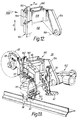
- the robot hand 20 comprises a body indicated generally at 24.
- the housing 24 has a casing 26, 28 containing a gear train to be described in more detail below by means of which a motor 30 (an electrical or pneumatic rotary motor for example) can drive various rollers.
- a motor 30 an electrical or pneumatic rotary motor for example
- One of these rollers is a take-up roller 32 which is mounted adjacent a free-running roller 33.
- Motor 30 is connected to drive roller 32 through a planetary gear box and the gear train (to be described below) within the casings 26 and 28.
- the casing 28 supports drive rollers 38 and 40 which are rotatable about vertical axes and are driven by motor 30 via the planetary gear box 36 and the gear train within housings 26 and 28.
- Casing 28 also supports a free-running horizontally rotatable top roller 42.
- a second motor 44 is mounted on the housing 24.
- This motor which may also be a rotary electrical or pneumatic motor, is connected through a gear box 46 for angularly moving a support arm 48 in the directions of the arrow A.
- Support arm 48 supports three claws 50 which engage a central boss in the cassette 22 which is shown dotted in Figure 5.
- Cassette 22 may take one of the forms disclosed in the published United Kingdom Patent Specification No. 2229702, though may take any other suitable form.
- Cassette 22 contains a coil of sealing strip 8, of the form shown in Figures 2,3 and 4, there being a predetermined length of such sealing strip within the cassette, this predetermined length matching the peripheral length of the flange 6 around the door opening 5.
- the housing 24 also supports a pneumatic piston-cylinder assembly 60 whose piston is oval in cross-section so that it cannot rotate.
- the piston-cylinder assembly 60 is connected to a cradle 62 which supports six contour rollers 63 to 68.
- Figure 8 which is a part view looking generally in the direction of the arrow VIII of Figure 5, and omits some of the contour rollers, illustrates the mechanism in greater detail.
- the cradle 62 is pivotally connected to a shaft 70 carried by a frame 72.
- the frame 72 comprises side members 74 and 76 which are interconnected by the shaft 70 and a rod 78.
- a pneumatic piston-cylinder assembly 80 contains a piston (not shown) having a piston rod 82 rotatably connected by a connection 84 to the upper end of the cradle 62.
- the piston-cylinder assembly 60 (see Figure 5), has a piston rod 88 connected to the side member 76.
- the piston-cylinder assembly 60 moves the frame 72 to and fro in the direction of the arrows B, so as to carry the cradle 62 with it and its contour rollers, while the piston-cylinder assembly 80 pivots the cradle 62 about the axis of the shaft 70 in the directions of the arrows C.
- the robot hand 20 is carried at the end of a robot arm (in the manner to be described in more detail below).
- the robot which may be a six-axis robot, swings the robot hand 20 to a position where there is a stack of cassettes 22.
- the robot moves the swinging arm 48 into such position that the claws 50 engage the bore of one of the cassettes in the stack and picks up the cassette in the manner shown in Figure 5.
- the robot then swings the robot hand 20 into position over the flange 6 of the door opening 5, so that the rollers 38 and 40 are positioned on opposite sides of the flange as shown in Figure 5.
- a short length of sealing strip 8 protrudes from each cassette when picked up.
- the orientation of the sealing strip within the cassette 22 is such that the open mouth of the splayed-apart channel of the gripping section 10 ( Figures 2,3 and 4) faces upwardly, as viewed in Figure 5.
- the first stage in the fitting process involves the movement of the cassette 22 generally to the right in the direction of the arrow D as shown in Figure 5.
- the claws 50 are mounted on a carrier 90 which is slidably mounted on the swinging arm 48 and is slid rightwards in the direction of the arrow D by a pneumatic or electric motor 91 mounted on the arm 48 and driving the carrier 90 through a rack and pinion arrangement 92.
- the sealing strip 8 carries a sensible mark (for example, a white dot) which is sensed by a photocell arrangement (not visible) located near guide roller 93.
- Logic circuitry associated with the photocell stops the motor 30 (though permits its subsequent free running) when this dot is sensed, the dot being positioned so that the take-up roller 32 drives just sufficient length of emerging sealing strip as is necessary for its initial end to engage the flange 6 as shown at F in Figure 5. It will be observed that the open splayed-apart mouth of the sealing strip 8 is now engaging the flange 6.
- the piston-cylinder 80 ( Figure 8) is now energised so as to pivot the cradle 62 in the direction C as shown in that Figure.
- Cradle 62 thus moves into the position shown in Figure 6, with the contour rollers now being moved clear of the sealing strip 8 and so that the cradle 62 is moved away from the flange 6.
- the contour rollers 63 to 68 are no longer required because the sealing strip 8 is constrained in its curved path (as illustrated dotted in Figure 5) by virtue of the fact that its end F is engaging the flange.
- the piston-cylinder assembly 60 is then energised so as to move the frame 72 (Fig. 8) to the right as viewed in that Figure.
- the cradle 62 thus now has the position shown in Figure 7 and is completely clear of the flange 6.
- rollers 38 and 40 are positioned apart by a predetermined distance so that they press the splayed-apart sides of the gripping section 10 towards each other into the configuration shown in Figure 2.
- these rollers are driven by the motor 30, they continue to move the robot hand 20 to the right, in the direction of the arrow G, thus causing the sealing strip 8 to be continuously drawn out of the cassette 22 and laid upon the flange 6 with its gripping section 10 initially in splayed-apart configuration, the gripping section then being converted into the configuration shown in Figure 2 by the rotating rollers 38,42.
- the robot and the support assembly arm (not shown) cause the robot hand 20 to apply downward pressure onto the sealing strip 8 as it is being mounted on the flange 6, this pressure being applied through the medium of the free-running roller 42.
- the gripping section 10 is thus properly seated on the flange 6.
- the free running roller 42 drives a tachometer 102 (see Figures 10 and 11) which thus produces an output dependent on its rotational speed which is a measure of the speed of movement of the robot hand 20 along the flange 6.
- a signal corresponding to this speed is fed to the control mechanism for the robot itself so that the robot can match the movement of its arm to the actual movement of the robot hand along the flange.
- motor 30 drives a shaft 110 via the gearbox 36.
- Shaft 110 is rigid with a gear 114 which rotates a gear 116 via intermediate gears 118 and 119.
- Gear 116 drives take-up roller 32 via a free wheel unit 120.
- the sealing strip 8 is positioned in the bight between the take-up roller and the free-running roller 34, Figure 9 showing the gripping section 10 and the sealing section 12 of the sealing strip.
- Shaft 110 is also rigid with a crown gear 122 engaging a second crown gear 124 driving a shaft 126.
- Shaft 126 drives the drive roller 38 and, through the intermediary of gears 128 and 130, the other drive roller 40.
- Figure 9 also shows the free-running top roller 42 and the tachometer 102 connected to it, although these are not part of the gear train being described.
- motor 30 When motor 30 is first energised, it drives the take-up roller 32 in the anti-clockwise direction as viewed in Figure 5, and in this way drives the emerging initial end of the sealing strip 8 along the curved path towards the flange 6 in the manner described above.
- This rotation of motor 30 also causes rotation of the drive rollers 38 and 40.
- the latter rotation is of no effect because they are clear of the flange 6 and the sealing strip has not yet become positioned between them.
- the photocell referred to above stops the motor 30 when the end F of the sealing strip has reached the flange 6 ( Figure 5). Motor 30 is then reversed. Because of the free wheel unit 120, it no longer rotates the take-up roller 32, although the latter is now free to rotate as the sealing strip 8 is continued to be drawn from the cassette 22 by virtue of movement of the robot hand along the flange (in the manner described). The reversed movement of the motor 30 causes the rollers 38 and 40 to rotate in the correct rotary directions to drive the robot hand 20 in the direction of the arrow G ( Figure 5). During the initial motion of motor 30, rollers 38 and 40 clearly rotate in the opposite directions to these "correct" directions; however, this is immaterial because rollers 38 and 40, being clear of the sealing strip at this time, have no effect.
- Figure 10 illustrates how the gears referred to in Figure 9 are arranged within the casings 26 and 28.
- the robot hand 20 As the robot hand 20 travels around the door opening, its orientation will have to change at each end or corner in the opening.
- the robot hand At the points indicated at J,K,L,M and N in Figure 1 the robot hand is caused to turn angularly by an appropriate distance (90 degrees in the case of points J,K and N), turning about the sixth axis of the robot which is aligned with the centre of the radius of the particular bend or corner.
- motor 44 can be energised at appropriate points in the movement around the door opening to adjust the position of the cassette by turning the swing arm 48, as shown in Figures 1 and 11.
- the carrier 90 ( Figure 5) can be slid in the direction D and in the reverse direction for the same purpose.
- Figure 12 shows the support assembly 150 which is fitted to the end of the robot arm 152 ( Figure 13).
- the support assembly comprises a member 154 which is rigid with the arm 152 and can be angularly turned by the arm about an axis 156 (the robot's sixth axis).
- Member 154 is rigid with a first support plate 158 which is attached to a second support plate 160.
- the plates 158 and 160 are linked together by resilient shock absorbing means (not shown) which permits relative movement between the two plates in the directions indicated at P by plus and minus 12 millimetres.
- Plate 160 rigidly supports a vertical pillar 162 carrying the robot hand holder 164. The latter is slidable relative to the member 162 in the directions Q within a range of plus and minus 40 millimetres.
- Figure 13 shows how the support assembly 150 is actually attached to the robot hand itself.
- the limited ranges of movement in the directions P and Q permit some lattitude in the programming of the robot's movements and enable account to be taken of the inevitable tolerances in the dimensions of the vehicle body and its positioning on the assembly track.
- the robot could be programmed to move the robot hand in a series of straight lines, corresponding to the approximately straight lengths of the flange, with any deviations in the flange from actual straight lines being accommodated by the limited ranges of movement in the directions P and Q.
- Figure 14 which is a view looking in the direction of the arrow XIV of Figure 12 but with the support assembly 150 fitted to the robot hand 20, shows how the support assembly 150 may carry pointers 170,172 to indicate the amount of relative movement in the directions P,Q ( Figure 12), as a programming aid.
- the robot As the robot carries the robot hand around the door opening, it applies a substantially constant pressure to the outside of the base of the channel of the gripping section of the sealing strip 8 (via the top roller 42, see Fig. 5). Fitting of the sealing strip to the flange normally starts along the bottom of the door opening (between points J and K in Figure 1) and the exerted pressure is approximately 4 bar. This pressure is maintained as the robot hand travels around the door opening and the robot therefore has to take account of the changing effect of the weight of the robot hand itself.
- a constant thrust unit 166 (see Figure 12), acting between the member 162 and the robot hand support 164, helps to maintain this constant pressure.
- Figures 15 and 16 correspond to Figures 10 and 13 respectively and show a modification.
- the modification comprises the provision of an additional electric motor 180 which is connected to drive the roller 32 and the removal of the connections via gears 118 and 119 (see Figure 10) between motor 30 and roller 32.
- the drive to the rollers 38 and 40 on the one hand and the drive to the roller 32 on the other hand are completely separate and are derived from separately controllable motors 30 and 180 respectively. The operation is otherwise the same.
Landscapes
- Engineering & Computer Science (AREA)
- Mechanical Engineering (AREA)
- Manufacturing & Machinery (AREA)
- Chemical & Material Sciences (AREA)
- Combustion & Propulsion (AREA)
- Transportation (AREA)
- Automobile Manufacture Line, Endless Track Vehicle, Trailer (AREA)
- Automatic Assembly (AREA)
Abstract
Description
- The invention relates to robot arrangement for fitting a length of channel-shaped strip onto a mounting flange or the like, comprising mounting mean, means on the mounting means for supporting the sealing strip in a manner permitting it to be driven longitudinally, constraining means on the mounting means for constraining the strip to follow a predetermined curved path as it moves longitudinally so as to present the mouth of the channel facing outwardly of the curved path, and robot means for positioning the mounting means in juxtaposition with the flange so that the mouth of the channel of the strip at the distal end of the curved path embraces the flange, and strip-pressing means for pressing the strip onto the flange.
- Such an arrangement is shown in GB-A-2 227 779. This known arrangement is intended for fitting onto a mounting flange or the like a channel-shaped sealing strip of conventional type in which the side walls are substantially parallel with each other. Such a sealing strip normally incorporates a metal carrier or reinforcement intended to provide resilience to the strip so that it firmly grips the mounting flange. However, a problem can arise with the use of a sealing strip of this form: the action of pressing it onto the flange with the use of this known type of robot arrangement tends to strain the sides of the strip at positions where the flange is relatively thick so that the strip may lose some of its resilience; but, in places where the flange is thinner, the flange may not be properly gripped by the sealing strip. It is known, for example from GB-PS-2 212 844, to apply a channel-shaped sealing strip to a flange with the side walls of the sealing strip initially splayed-apart, and then to press them towards each other into gripping engagement with the flange. However, the known robot arrangement is not suitable for fitting such a sealing strip to a flange. The invention is intended to overcome this problem.
- In accordance with the invention, therefore, the known robot arrangement is characterised in that the side walls of the channel of the strip are initially splayed apart when it is supported on the mounting means and driven along the curved path, and in that the strip-pressing means comprises at least two drive rollers mounted on the mounting means adjacent the distal end of the curved path and rotatable about parallel axes spaced apart by such distance as to receive the sealing strip between them as it embraces the flange, and motor means on the mounting means for driving the rollers in such predetermined rotary directions that they contact the splayed-apart side walls of the sealing strip and press them into gripping engagement with the sides of the flange and drive the mounting means along the flange, drawing the sealing strip longitudinally along the curved path and onto the flange.
- Apparatus embodying the invention for fitting a sealing strip onto a motor vehicle door opening will now be described, by way of example only, with reference to the accompanying drawings in which:
- Figure 1 is a side view of the door opening showing the apparatus in block form only;
- Figure 2 is a cross-section of the sealing strip when finally fitted onto a flange surrounding the opening;
- Figures 3 and 4 are cross-sections of the sealing strip in the form which it has before it is fitted onto the flange, and when it is initially fitted onto the flange, respectively;
- Figure 5 is a perspective view of a robot hand forming part of the apparatus and in the state which it assumes during an initial stage in the fitting process;
- Figure 6 corresponds to Figure 5 but shows the robot hand in a later state;
- Figure 7 corresponds to Figures 5 and 6 but shows a still later state;
- Figure 8 shows an enlarged perspective view of part of the robot hand to illustrate part of its mechanism in greater detail;
- Figure 9 shows the gear train within the robot hand;
- Figure 10 is a diagrammatic view of the robot hand but showing the gear train of Figure 9 in phantom form and with other parts omitted;
- Figure 11 shows the robot hand and illustrates it at another stage during the fitting process;
- Figure 12 illustrates a support assembly by means of which the robot hand can be attached to the robot arm;
- Figure 13 shows how the support assembly of Figure 12 is fitted to the robot hand;
- Figure 14 shows a side view of the support assembly of Figure 12 looking in the direction of the arrow XIV of Figure 12; and
- Figures 15 and 16 correspond to Figures 10 and 13 respectively but show a modified construction.
- Figure 1 shows the door opening 5 of a motor vehicle body. This door opening is defined by a
flange 6 which runs around the door opening, lying generally in its plane, and which is formed where the inner and outer body panels come together, and are welded, at the door opening. In order to provide a seal for the door opening 5, the manufacture of the car body involves the fitting of a sealing strip (see Figures 2,3 and 4) onto theflange 6. Figure 2 shows a cross-section through the flange with thesealing strip 8 in position thereon. As shown, thesealing strip 8 comprises a channel-shaped gripping section 10 which, in use, embracingly grips theflange 6 and supports a softtubular sealing section 12, so that the sealing strip runs around the door opening, with thesealing section 12 on the outside of the opening. When the door (not shown) closes onto theopening 5, it partially compresses thetubular sealing section 12 so as to form a weather-proof seal. - The
gripping section 10 is of channel-shape in cross-section and (in this case) is made ofextruded rubber material 15 with an embedded channel-shaped metal carrier 16. The extruded material definesgripping lips lip 19 is directed oppositely to the other lips to provide improved sealing. - As illustrated, the extruded material forming the
gripping section 10 is integrally extruded with further extruded rubber forming thetubular sealing section 12. Instead, however, thegripping section 10 may be manufactured separately, and thetubular sealing section 12 attached to it afterwards, as by means of adhesive. In such a case, for example, the extruded material for thegripping section 10 may be plastics. - The extruded material may be extruded so that different parts have different hardness. Thus, the
lips gripping section 10. This relative softness helps their sealing and gripping function. The extruded material of thetubular sealing section 12 may be of foamed or cellular construction to improve sealing efficiency. - The
metal carrier 16 may take any suitable form. For example, it may be made of continuous metal strip. Instead, however, it can be made of U-shaped links either connected together by short flexible connecting links or entirely separate. Another possibility is to construct the carrier from wire looped to and fro. - Figure 3 shows the configuration of the sealing strip before it is fitted on the flange. It will be apparent that the sides of the channel of the
gripping section 10 are splayed apart as compared with the configuration shown in Figure 2. This splayed apart configuration facilitates the assembly of thesealing strip 8 onto the flange 6 - as shown in Figure 4. After thesealing strip 8 has been fitted onto theflange 6 in the splayed-apart configuration shown in Figures 3 and 4, the splayed-apart sides of the channel are then pressed towards each other so that they assume the configuration shown in Figure 2, firmly gripping the sides of the flange and holding thesealing strip 8 securely in position on the flange. - The apparatus and methods now to be described are concerned with the automatic fitting of the
sealing strip 8 onto theflange 6, the fitting process involving the fitting of theseal 8 onto the flange in the splayed-apart configuration shown in Figures 3 and 4 and the subsequent step of forcing the channel walls of the gripping section towards each other to produce the result shown in Figure 2. - The apparatus comprises several parts: a robot (not shown) having a robot arm (see Fig. 13) which carries a support assembly (illustrated in Figures 12 and 13), and a
robot hand 20 which is fitted to the support assembly and will now be described in detail with reference to the various Figures of the drawings. Figure 1 illustrates therobot hand 20 in block form only and shows how it carries a cassette 22 (to be described in more detail below) containing a coil of thesealing strip 8 which is fed out of the cassette by therobot hand 20 which constrains it to follow a curved path and mounts it on theflange 6, whereafter the robot hand travels along the flange and rollers, to be described in detail below, force the splayed-apart sides of the gripping section towards each other. This process would normally be carried out before the door is fitted to the body. Figure 1 shows therobot hand 20 in two different positions and attitudes as it travels along the flange. - Referring to Figure 5, the
robot hand 20 comprises a body indicated generally at 24. Thehousing 24 has acasing up roller 32 which is mounted adjacent a free-runningroller 33. Motor 30 is connected to driveroller 32 through a planetary gear box and the gear train (to be described below) within thecasings casing 28 supportsdrive rollers motor 30 via theplanetary gear box 36 and the gear train withinhousings top roller 42. - Also mounted on the
housing 24 is asecond motor 44. This motor, which may also be a rotary electrical or pneumatic motor, is connected through agear box 46 for angularly moving asupport arm 48 in the directions of the arrowA. Support arm 48 supports threeclaws 50 which engage a central boss in thecassette 22 which is shown dotted in Figure 5.Cassette 22 may take one of the forms disclosed in the published United Kingdom Patent Specification No. 2229702, though may take any other suitable form.Cassette 22 contains a coil ofsealing strip 8, of the form shown in Figures 2,3 and 4, there being a predetermined length of such sealing strip within the cassette, this predetermined length matching the peripheral length of theflange 6 around the door opening 5. - The
housing 24 also supports a pneumatic piston-cylinder assembly 60 whose piston is oval in cross-section so that it cannot rotate. The piston-cylinder assembly 60 is connected to acradle 62 which supports sixcontour rollers 63 to 68. Figure 8, which is a part view looking generally in the direction of the arrow VIII of Figure 5, and omits some of the contour rollers, illustrates the mechanism in greater detail. As will be seen, thecradle 62 is pivotally connected to ashaft 70 carried by aframe 72. Theframe 72 comprisesside members shaft 70 and arod 78. A pneumatic piston-cylinder assembly 80 contains a piston (not shown) having apiston rod 82 rotatably connected by aconnection 84 to the upper end of thecradle 62. The piston-cylinder assembly 60 (see Figure 5), has apiston rod 88 connected to theside member 76. In a manner and for purposes to be described, the piston-cylinder assembly 60 moves theframe 72 to and fro in the direction of the arrows B, so as to carry thecradle 62 with it and its contour rollers, while the piston-cylinder assembly 80 pivots thecradle 62 about the axis of theshaft 70 in the directions of the arrows C. - The operation of the robot hand as so rear described will now be explained with particular reference to Figures 4,5 and 6.
- As already explained, the
robot hand 20 is carried at the end of a robot arm (in the manner to be described in more detail below). The robot, which may be a six-axis robot, swings therobot hand 20 to a position where there is a stack ofcassettes 22. The robot moves the swingingarm 48 into such position that theclaws 50 engage the bore of one of the cassettes in the stack and picks up the cassette in the manner shown in Figure 5. The robot then swings therobot hand 20 into position over theflange 6 of thedoor opening 5, so that therollers - A short length of sealing
strip 8 protrudes from each cassette when picked up. The orientation of the sealing strip within thecassette 22 is such that the open mouth of the splayed-apart channel of the gripping section 10 (Figures 2,3 and 4) faces upwardly, as viewed in Figure 5. The first stage in the fitting process involves the movement of thecassette 22 generally to the right in the direction of the arrow D as shown in Figure 5. As shown in Figure 5, theclaws 50 are mounted on acarrier 90 which is slidably mounted on the swingingarm 48 and is slid rightwards in the direction of the arrow D by a pneumatic orelectric motor 91 mounted on thearm 48 and driving thecarrier 90 through a rack andpinion arrangement 92. - This rightward movement of the cassette moves the protruding end of the sealing
strip 8 into the bight between the take-uproller 32 and the free-running roller 34 (Figure 5). In a manner to be described,motor 30 is then energised and rotatesroller 32 in an anti-clockwise direction (as viewed in Figure 5) so as to pull thesealing strip 8 from the cassette 54. The emerging sealing strip passes over guides 93 and 94 and engages thecontour rollers 63 to 68 in that order, these rollers constraining the the emerging sealing strip to follow the curved path shown in Figure 5, the strip passing further free-runningguide rollers - Distanced by a predetermined distance from its emerging initial end, the sealing
strip 8 carries a sensible mark (for example, a white dot) which is sensed by a photocell arrangement (not visible) located nearguide roller 93. Logic circuitry associated with the photocell stops the motor 30 (though permits its subsequent free running) when this dot is sensed, the dot being positioned so that the take-uproller 32 drives just sufficient length of emerging sealing strip as is necessary for its initial end to engage theflange 6 as shown at F in Figure 5. It will be observed that the open splayed-apart mouth of the sealingstrip 8 is now engaging theflange 6. - The piston-cylinder 80 (Figure 8) is now energised so as to pivot the
cradle 62 in the direction C as shown in that Figure.Cradle 62 thus moves into the position shown in Figure 6, with the contour rollers now being moved clear of the sealingstrip 8 and so that thecradle 62 is moved away from theflange 6. Thecontour rollers 63 to 68 are no longer required because thesealing strip 8 is constrained in its curved path (as illustrated dotted in Figure 5) by virtue of the fact that its end F is engaging the flange. The piston-cylinder assembly 60 is then energised so as to move the frame 72 (Fig. 8) to the right as viewed in that Figure. Thecradle 62 thus now has the position shown in Figure 7 and is completely clear of theflange 6. -
Motor 30 is now caused (in the manner to be explained) to rotate therollers robot hand 20 slightly along the flange as shown by the arrow G in Figure 6. This movement causes the initial end F of the sealingstrip 8 to be laid down upon theflange 6 and to be embraced by therollers section 10 towards each other into the configuration shown in Figure 2. Because these rollers are driven by themotor 30, they continue to move therobot hand 20 to the right, in the direction of the arrow G, thus causing the sealingstrip 8 to be continuously drawn out of thecassette 22 and laid upon theflange 6 with its grippingsection 10 initially in splayed-apart configuration, the gripping section then being converted into the configuration shown in Figure 2 by the rotatingrollers robot hand 20 to apply downward pressure onto the sealingstrip 8 as it is being mounted on theflange 6, this pressure being applied through the medium of the free-runningroller 42. The grippingsection 10 is thus properly seated on theflange 6. - In Figures 5,6, and 7, the sealing
strip 8 is illustrated without the sealing section 12 (see Figures 2,3 and 4). However, this would of course be present and theroller 40 would apply side pressure to the corresponding splayed-apart side wall of the channel of the grippingsection 10 via thesealing section 12. - The
free running roller 42 drives a tachometer 102 (see Figures 10 and 11) which thus produces an output dependent on its rotational speed which is a measure of the speed of movement of therobot hand 20 along theflange 6. A signal corresponding to this speed is fed to the control mechanism for the robot itself so that the robot can match the movement of its arm to the actual movement of the robot hand along the flange. - The process continues until the full length of the sealing
strip 8 has been laid on the flange. When the final end of the sealing strip passes over the photocell referred to above, it is sensed and causes themotor 30 to cease rotating therollers robot hand 20 clear of the body ready for a repeat of the process described on the next vehicle body arriving on the assembly track. - The manner in which the
motor 30 drives the take-uproller 32 and thedrive rollers - Referring to Figure 9,
motor 30 drives ashaft 110 via thegearbox 36.Shaft 110 is rigid with agear 114 which rotates agear 116 viaintermediate gears Gear 116 drives take-uproller 32 via afree wheel unit 120. As shown in diagrammatic form in Figure 9, the sealingstrip 8 is positioned in the bight between the take-up roller and the free-runningroller 34, Figure 9 showing the grippingsection 10 and the sealingsection 12 of the sealing strip. -
Shaft 110 is also rigid with acrown gear 122 engaging asecond crown gear 124 driving ashaft 126.Shaft 126 drives thedrive roller 38 and, through the intermediary ofgears other drive roller 40. - Figure 9 also shows the free-running
top roller 42 and thetachometer 102 connected to it, although these are not part of the gear train being described. - When
motor 30 is first energised, it drives the take-uproller 32 in the anti-clockwise direction as viewed in Figure 5, and in this way drives the emerging initial end of the sealingstrip 8 along the curved path towards theflange 6 in the manner described above. This rotation ofmotor 30 also causes rotation of thedrive rollers flange 6 and the sealing strip has not yet become positioned between them. - In the manner already described, the photocell referred to above stops the
motor 30 when the end F of the sealing strip has reached the flange 6 (Figure 5).Motor 30 is then reversed. Because of thefree wheel unit 120, it no longer rotates the take-uproller 32, although the latter is now free to rotate as the sealingstrip 8 is continued to be drawn from thecassette 22 by virtue of movement of the robot hand along the flange (in the manner described). The reversed movement of themotor 30 causes therollers robot hand 20 in the direction of the arrow G (Figure 5). During the initial motion ofmotor 30,rollers rollers - Figure 10 illustrates how the gears referred to in Figure 9 are arranged within the
casings - As the
robot hand 20 travels around the door opening, its orientation will have to change at each end or corner in the opening. At the points indicated at J,K,L,M and N in Figure 1 the robot hand is caused to turn angularly by an appropriate distance (90 degrees in the case of points J,K and N), turning about the sixth axis of the robot which is aligned with the centre of the radius of the particular bend or corner. - As the robot hand travels around the door opening, it is also necessary to ensure that the
cassette 22 does not interfere with the door opening itself or other adjacent body parts. In order to assist in this,motor 44 can be energised at appropriate points in the movement around the door opening to adjust the position of the cassette by turning theswing arm 48, as shown in Figures 1 and 11. In addition, the carrier 90 (Figure 5) can be slid in the direction D and in the reverse direction for the same purpose. - Figure 12 shows the
support assembly 150 which is fitted to the end of the robot arm 152 (Figure 13). The support assembly comprises amember 154 which is rigid with thearm 152 and can be angularly turned by the arm about an axis 156 (the robot's sixth axis).Member 154 is rigid with afirst support plate 158 which is attached to asecond support plate 160. Theplates Plate 160 rigidly supports avertical pillar 162 carrying therobot hand holder 164. The latter is slidable relative to themember 162 in the directions Q within a range of plus and minus 40 millimetres. - Figure 13 shows how the
support assembly 150 is actually attached to the robot hand itself. The limited ranges of movement in the directions P and Q permit some lattitude in the programming of the robot's movements and enable account to be taken of the inevitable tolerances in the dimensions of the vehicle body and its positioning on the assembly track. Thus, the robot could be programmed to move the robot hand in a series of straight lines, corresponding to the approximately straight lengths of the flange, with any deviations in the flange from actual straight lines being accommodated by the limited ranges of movement in the directions P and Q. Figure 14, which is a view looking in the direction of the arrow XIV of Figure 12 but with thesupport assembly 150 fitted to therobot hand 20, shows how thesupport assembly 150 may carry pointers 170,172 to indicate the amount of relative movement in the directions P,Q (Figure 12), as a programming aid. - As the robot carries the robot hand around the door opening, it applies a substantially constant pressure to the outside of the base of the channel of the gripping section of the sealing strip 8 (via the
top roller 42, see Fig. 5). Fitting of the sealing strip to the flange normally starts along the bottom of the door opening (between points J and K in Figure 1) and the exerted pressure is approximately 4 bar. This pressure is maintained as the robot hand travels around the door opening and the robot therefore has to take account of the changing effect of the weight of the robot hand itself. A constant thrust unit 166 (see Figure 12), acting between themember 162 and therobot hand support 164, helps to maintain this constant pressure. - Figures 15 and 16 correspond to Figures 10 and 13 respectively and show a modification. The modification comprises the provision of an additional
electric motor 180 which is connected to drive theroller 32 and the removal of the connections viagears 118 and 119 (see Figure 10) betweenmotor 30 androller 32. Thus, in the modified arrangement the drive to therollers roller 32 on the other hand are completely separate and are derived from separatelycontrollable motors
Claims (16)
- A robot arrangement for fitting a length of channel-shaped strip onto a mounting flange or the like, comprising mounting means (20), means (22) on the mounting means (20) for supporting the sealing strip (8) in a manner permitting it to be driven longitudinally, constraining means (62-68) on the mounting means (20) for constraining the strip (8) to follow a predetermined curved path as it moves longitudinally so as to present the mouth of the channel facing outwardly of the curved path, supporting means (152) for positioning the mounting means (20) in juxtaposition with the flange (6) so that the mouth of the channel of the strip (8) at the distal end of the curved path embraces the flange (6), and strip-pressing means (38,40,42) for pressing the strip (8) onto the flange (6), characterised in that the side walls of the channel of the strip (8) are initially splayed apart when it is supported on the mounting means (20) and driven along the curved path, and in that the strip-pressing means comprises at least two drive rollers (38,40) mounted on the mounting means (20) adjacent the distal end of the curved path and rotatable about parallel axes spaced apart by such distance as to receive the splayed-apart side walls of the sealing strip (8) between them as it embraces the flange (6), and motor means (30) on the mounting means (20) for driving the rollers (38,40) in such predetermined rotary directions that they contact splayed-apart side walls of the sealing strip (8) and press them into gripping engagement with the sides of the flange (6) and drive the mounting means (20) along the flange (6), drawing the sealing strip (8) longitudinally along the curved path and onto the flange (6).
- An arrangement according to claim 1, characterised by transporting means (60,72,80) on the mounting means (20) for moving the constraining means (62-68) clear of the curved path when the strip (8) embraces the flange (6).
- An arrangement according to claim 2, characterised in that the constraining means comprises a member (62) carrying at least one guide roller (63-68), the member (62) being mounted for pivotal movement on the mounting means (20) so as to pivot the guide roller (63-68) into and out of engagement with the sealing strip (8) in the curved path and also mounted for translational movement in a direction transverse to the curved path.
- An arrangement according to claim 3, characterised in that the transporting means includes piston-cylinder means (60,80) connected to the member (62) for causing the said pivotal and translational movement thereof.
- An arrangement according to any preceding claim, characterised in that the sealing strip (8) is initially stored in a coil thereof of predetermined length in a cassette (22) which is adapted to be supported by the mounting means (20) for dispensing therefrom.
- An arrangement according to claim 5, characterised by motor means (44) carried by the mounting means (20) for adjusting the position of the cassette (22) thereon.
- An arrangement according to claim 5, characterised in that the motor means (44,91) is capable of adjusting the position of the cassette (22) in two transverse directions.
- An arrangement according to any preceding claim, characterised by initial drive means (30,32) for engaging the initial end of the strip (8) protruding from the cassette (22) and for feeding the end into and along the curved path, and energisable to cause the initial end of the strip (8) to be fed to the distal end of the curved path.
- An arrangement according to claim 8, characterised by sensing means for sensing the passage of the strip (8) therepast and to control the initial drive means (30,32) to feed such length of the strip (8) as feeds the initial end of the strip (8) to the end of the curved path.
- An arrangement according to claim 8 or 9, characterised in that the initial drive means (30,32) comprises a take-up roller (32) driven by the motor means (30) which drives the drive rollers (38,40).
- An arrangement according to claim 10, characterised by free wheel means (120) interposed between the motor means (30) and the take-up roller (32), whereby the motor means (30) drives the take-up roller (32) through a predetermined amount of angular movement via the free wheel means (120) and simultaneously drives the drive rollers (38,40) in directions opposite to the said predetermined directions, the predetermined amount of angular movement being such as to feed the initial end of the strip (8) to the end of the curved path; and in that, at the completion of the predetermined amount of angular movement, the motor means (30) drives the drive rollers (38,40) in the said predetermined directions and is prevented from driving the take-up roller (32) by the free wheel means (120), the free wheel means (120) permitting free-wheeling of the take-up roller (32) in response to subsequent passage of the sealing strip (8) along the curved path.
- An arrangement according to claim 8 or 9, characterised in that the initial drive means includes a motor (180) which is additional to the motor means (30) driving the drive rollers (38,40).
- An arrangement according to any preceding claim, characterised by a further roller (42) mounted adjacent to the drive rollers (38,40) but rotatable about an axis transverse thereto so as to engage the sealing strip (8) on the mounting flange (6) and to be driven by such engagement as the robot arrangement moves along the flange and lays the sealing strip (8) thereon.
- An arrangement according to claim 13, characterised by speed measuring means (102) for measuring the speed of rotation of the further roller (42) and controlling the robot to move the robot arrangement along the mounting flange (6) at a corresponding speed.
- An arrangement according to claim 14, characterised by support means (150) interposed between the robot and the robot arrangement and permitting a predetermined degree of limited movement therebetween to accommodate programming tolerances and dimensional tolerances in the position of the mounting flange (6).
- An arrangement according to claim 14, characterised by indicating means (170,172) on the support means (150) for indicating the extent of such limited movement at any time.
Applications Claiming Priority (2)
| Application Number | Priority Date | Filing Date | Title |
|---|---|---|---|
| GB919102042A GB9102042D0 (en) | 1991-01-30 | 1991-01-30 | Apparatus and method for fitting a flexible strip |
| GB9102042 | 1991-01-30 |
Publications (2)
| Publication Number | Publication Date |
|---|---|
| EP0497048A1 true EP0497048A1 (en) | 1992-08-05 |
| EP0497048B1 EP0497048B1 (en) | 1994-08-10 |
Family
ID=10689271
Family Applications (1)
| Application Number | Title | Priority Date | Filing Date |
|---|---|---|---|
| EP91311296A Expired - Lifetime EP0497048B1 (en) | 1991-01-30 | 1991-12-04 | Apparatus and method for fitting a flexible strip |
Country Status (6)
| Country | Link |
|---|---|
| US (1) | US5237741A (en) |
| EP (1) | EP0497048B1 (en) |
| JP (1) | JP3281402B2 (en) |
| DE (1) | DE69103395T2 (en) |
| ES (1) | ES2057787T3 (en) |
| GB (1) | GB9102042D0 (en) |
Cited By (14)
| Publication number | Priority date | Publication date | Assignee | Title |
|---|---|---|---|---|
| FR2695587A1 (en) * | 1992-09-11 | 1994-03-18 | Peugeot | Robotic tool fixture for extruding watertight jointing - uses elastic mountings between supporting gun box and tool body ensuring operating equilibrium and contact with work piece |
| EP0631852A1 (en) * | 1993-06-30 | 1995-01-04 | STANDARD PRODUCTS ATLANTIC Société anonyme | Device for placing sealing elements |
| EP0647501A1 (en) * | 1993-10-06 | 1995-04-12 | Draftex Industries Limited | Strip fitting apparatus and methods |
| EP0856426A1 (en) * | 1997-02-04 | 1998-08-05 | Standard Products Industriel | Weatherstrip for automotive vehicles |
| GB2324327A (en) * | 1997-04-18 | 1998-10-21 | Standard Prod Ltd | Variable centre worm and wheel clinching tool |
| WO2000045989A1 (en) * | 1999-02-03 | 2000-08-10 | Saar-Gummiwerk Gmbh | Device for mounting shaped door seals using an sas-sgm-type method |
| EP0818277A3 (en) * | 1996-07-12 | 2001-08-22 | Standard Products Limited | Clinching apparatus |
| DE10023332B4 (en) * | 2000-05-12 | 2006-09-21 | Daimlerchrysler Ag | Device for applying an edge protection profile to the door opening of a vehicle body |
| EP1440831A3 (en) * | 2003-01-24 | 2006-10-11 | Siegfried-W. Grunwald | Mounting device for profiles |
| WO2006111117A1 (en) * | 2005-04-20 | 2006-10-26 | Volkswagen Ag | Device for fixing a profiled sealing element to a flange |
| EP2067645A3 (en) * | 2007-12-05 | 2009-11-18 | Grohmann Engineering GmbH | Method and device for applying seal profiles |
| CN106608089A (en) * | 2015-10-29 | 2017-05-03 | 保定威奕汽车有限公司 | On-line cloth sticking device for workpieces |
| CN112318100A (en) * | 2020-11-18 | 2021-02-05 | 湖南富而康科贸新材料有限公司 | A adhesive pressing device for wood door and window production usefulness |
| CN112721207A (en) * | 2020-12-01 | 2021-04-30 | 机械工业第九设计研究院有限公司 | Automobile sealing strip installation device |
Families Citing this family (19)
| Publication number | Priority date | Publication date | Assignee | Title |
|---|---|---|---|---|
| FR2730444B1 (en) * | 1995-02-10 | 1997-04-11 | Peugeot | TOOL ASSOCIATED WITH A ROBOT FOR THE AUTOMATIC LAYING OF A SEAL |
| US5735032A (en) * | 1996-05-15 | 1998-04-07 | Chrysler Corporation | Trim welt installation tool |
| US5875670A (en) * | 1996-07-31 | 1999-03-02 | The Standard Products Company | Tool for roll crimping a flange cover |
| US6205651B1 (en) * | 1999-03-29 | 2001-03-27 | Joseph H. Warner | Door panel molding installation machine |
| US6311378B1 (en) | 2000-02-16 | 2001-11-06 | Saargummi Americas, Inc. | Crimp on flange tool for doorseals |
| FR2839039B1 (en) * | 2002-04-24 | 2004-07-09 | Peugeot Citroen Automobiles Sa | DEVICE FOR LAYING A SEAL ON A MOTOR VEHICLE BODY, AND ASSOCIATED METHOD |
| US6978650B2 (en) * | 2003-03-11 | 2005-12-27 | Schlegel Corporation | Contact surface for a crimping roller in a roll forming tool |
| JP4482425B2 (en) * | 2004-11-04 | 2010-06-16 | 本田技研工業株式会社 | Open seal mounting method and mounting device |
| JP2007253794A (en) * | 2006-03-23 | 2007-10-04 | Toyoda Gosei Co Ltd | Weather strip mounting method |
| US20080096003A1 (en) * | 2006-10-20 | 2008-04-24 | Horst Dragon | Bonding of sealing, trimming or guiding strips |
| US8322005B2 (en) * | 2008-10-23 | 2012-12-04 | Pow Specialty Equipment Inc. | Weather strip installation device |
| US9120369B2 (en) * | 2011-12-19 | 2015-09-01 | Fca Us Llc | Glass run installation tool |
| US9003628B2 (en) | 2012-01-18 | 2015-04-14 | Toyota Motor Engineering & Manufacturing North America, Inc. | Roof trim ditch molding fitting tool |
| DE102016103490A1 (en) * | 2016-02-26 | 2017-08-31 | Cqlt Saargummi Technologies S.À.R.L. | Method for producing a sealing element |
| DE102016221271B4 (en) * | 2016-10-28 | 2022-02-24 | Ford Global Technologies, Llc | Method and apparatus for applying a flexible seal to the perimeter of a component |
| CN106891146A (en) * | 2017-04-20 | 2017-06-27 | 北京正木激光设备有限公司 | A kind of novel spot gluing assembles combination machine |
| CN107553390A (en) * | 2017-09-05 | 2018-01-09 | 滁州克莱帝玻璃科技有限公司 | A kind of refrigerator glass partition panel installs equipment |
| CN110774602A (en) * | 2019-11-28 | 2020-02-11 | 厦门航天思尔特机器人系统股份公司 | A door panel rubber strip automatic assembly equipment |
| DE102020118940A1 (en) * | 2020-07-17 | 2022-01-20 | Aytec Automation Gmbh | Device for applying a rubber profile |
Citations (7)
| Publication number | Priority date | Publication date | Assignee | Title |
|---|---|---|---|---|
| DE3541865A1 (en) * | 1985-11-27 | 1987-06-04 | Volkswagen Ag | Device for automatically fitting an elongated material onto a flange |
| EP0253599A2 (en) * | 1986-07-18 | 1988-01-20 | General Motors Corporation | Installing weather stripping in a door or like opening |
| FR2626805A1 (en) * | 1988-02-10 | 1989-08-11 | Draftex Ind Ltd | JOINT AND JOINT MOUNTING APPARATUS |
| GB2227779A (en) * | 1988-12-20 | 1990-08-08 | Draftex Ind Ltd | Fitting sealing strips |
| FR2642691A1 (en) * | 1989-01-17 | 1990-08-10 | Peugeot | Apparatus intended to be fixed to a wrist of a robot for fitting a door seal |
| GB2229702A (en) * | 1989-02-04 | 1990-10-03 | Draftex Ind Ltd | Coil feed |
| JPH033734A (en) * | 1989-05-31 | 1991-01-09 | Mitsubishi Motors Corp | Parts assembling device |
Family Cites Families (3)
| Publication number | Priority date | Publication date | Assignee | Title |
|---|---|---|---|---|
| GB8927677D0 (en) * | 1989-12-07 | 1990-02-07 | Draftex Ind Ltd | Apparatus for fitting flexible strips |
| GB2244302B (en) * | 1990-05-24 | 1994-01-19 | Ford Motor Co | Applying weather strips |
| US5295794A (en) * | 1993-01-14 | 1994-03-22 | The Nash Engineering Company | Liquid ring pumps with rotating liners |
-
1991
- 1991-01-30 GB GB919102042A patent/GB9102042D0/en active Pending
- 1991-12-04 ES ES91311296T patent/ES2057787T3/en not_active Expired - Lifetime
- 1991-12-04 EP EP91311296A patent/EP0497048B1/en not_active Expired - Lifetime
- 1991-12-04 DE DE69103395T patent/DE69103395T2/en not_active Expired - Fee Related
-
1992
- 1992-01-06 US US07/818,636 patent/US5237741A/en not_active Expired - Lifetime
- 1992-01-30 JP JP01508192A patent/JP3281402B2/en not_active Expired - Fee Related
Patent Citations (7)
| Publication number | Priority date | Publication date | Assignee | Title |
|---|---|---|---|---|
| DE3541865A1 (en) * | 1985-11-27 | 1987-06-04 | Volkswagen Ag | Device for automatically fitting an elongated material onto a flange |
| EP0253599A2 (en) * | 1986-07-18 | 1988-01-20 | General Motors Corporation | Installing weather stripping in a door or like opening |
| FR2626805A1 (en) * | 1988-02-10 | 1989-08-11 | Draftex Ind Ltd | JOINT AND JOINT MOUNTING APPARATUS |
| GB2227779A (en) * | 1988-12-20 | 1990-08-08 | Draftex Ind Ltd | Fitting sealing strips |
| FR2642691A1 (en) * | 1989-01-17 | 1990-08-10 | Peugeot | Apparatus intended to be fixed to a wrist of a robot for fitting a door seal |
| GB2229702A (en) * | 1989-02-04 | 1990-10-03 | Draftex Ind Ltd | Coil feed |
| JPH033734A (en) * | 1989-05-31 | 1991-01-09 | Mitsubishi Motors Corp | Parts assembling device |
Cited By (18)
| Publication number | Priority date | Publication date | Assignee | Title |
|---|---|---|---|---|
| FR2695587A1 (en) * | 1992-09-11 | 1994-03-18 | Peugeot | Robotic tool fixture for extruding watertight jointing - uses elastic mountings between supporting gun box and tool body ensuring operating equilibrium and contact with work piece |
| EP0631852A1 (en) * | 1993-06-30 | 1995-01-04 | STANDARD PRODUCTS ATLANTIC Société anonyme | Device for placing sealing elements |
| FR2707543A1 (en) * | 1993-06-30 | 1995-01-20 | Standard Products Atlantic | Device for installing a seal. |
| EP0647501A1 (en) * | 1993-10-06 | 1995-04-12 | Draftex Industries Limited | Strip fitting apparatus and methods |
| EP0818277A3 (en) * | 1996-07-12 | 2001-08-22 | Standard Products Limited | Clinching apparatus |
| EP0856426A1 (en) * | 1997-02-04 | 1998-08-05 | Standard Products Industriel | Weatherstrip for automotive vehicles |
| FR2759029A1 (en) * | 1997-02-04 | 1998-08-07 | Standard Products Ind | GASKET FOR MOTOR VEHICLES |
| GB2324327B (en) * | 1997-04-18 | 2001-06-13 | Standard Prod Ltd | Clinching tool with rotatable spindles driven by a worm and gear |
| GB2324327A (en) * | 1997-04-18 | 1998-10-21 | Standard Prod Ltd | Variable centre worm and wheel clinching tool |
| WO2000045989A1 (en) * | 1999-02-03 | 2000-08-10 | Saar-Gummiwerk Gmbh | Device for mounting shaped door seals using an sas-sgm-type method |
| DE10023332B4 (en) * | 2000-05-12 | 2006-09-21 | Daimlerchrysler Ag | Device for applying an edge protection profile to the door opening of a vehicle body |
| EP1440831A3 (en) * | 2003-01-24 | 2006-10-11 | Siegfried-W. Grunwald | Mounting device for profiles |
| WO2006111117A1 (en) * | 2005-04-20 | 2006-10-26 | Volkswagen Ag | Device for fixing a profiled sealing element to a flange |
| EP2067645A3 (en) * | 2007-12-05 | 2009-11-18 | Grohmann Engineering GmbH | Method and device for applying seal profiles |
| CN106608089A (en) * | 2015-10-29 | 2017-05-03 | 保定威奕汽车有限公司 | On-line cloth sticking device for workpieces |
| CN106608089B (en) * | 2015-10-29 | 2019-01-25 | 保定威奕汽车有限公司 | The online fabric sticking device of product |
| CN112318100A (en) * | 2020-11-18 | 2021-02-05 | 湖南富而康科贸新材料有限公司 | A adhesive pressing device for wood door and window production usefulness |
| CN112721207A (en) * | 2020-12-01 | 2021-04-30 | 机械工业第九设计研究院有限公司 | Automobile sealing strip installation device |
Also Published As
| Publication number | Publication date |
|---|---|
| JPH04310329A (en) | 1992-11-02 |
| GB9102042D0 (en) | 1991-03-13 |
| US5237741A (en) | 1993-08-24 |
| EP0497048B1 (en) | 1994-08-10 |
| DE69103395T2 (en) | 1994-12-15 |
| JP3281402B2 (en) | 2002-05-13 |
| ES2057787T3 (en) | 1994-10-16 |
| DE69103395D1 (en) | 1994-09-15 |
Similar Documents
| Publication | Publication Date | Title |
|---|---|---|
| EP0497048B1 (en) | Apparatus and method for fitting a flexible strip | |
| US4760636A (en) | Apparatus of a robot for installing weather stripping in a door or like opening | |
| US5065486A (en) | Apparatus for fitting flexible strips | |
| US4780943A (en) | Apparatus and method of a robot for installing weather stripping in a door or like opening | |
| US5048170A (en) | Apparatus for fitting flexible strips | |
| US4996756A (en) | Apparatus for fitting sealing and trimming strips | |
| US5115551A (en) | Method for fitting a flexible strip | |
| US5068952A (en) | Apparatus for fitting flexible strips | |
| US6691388B1 (en) | Strip fitting tools | |
| CA2004418C (en) | Apparatus and method for fitting a flexible strip | |
| CA2008521A1 (en) | Strip handling apparatus and methods | |
| DE59102373D1 (en) | Motorized window regulator drive for a motor vehicle. | |
| US4897913A (en) | Method of using a robot for installing weather stripping in a door or like opening | |
| US5067225A (en) | Method of a robot for installing weather stripping in a door or like opening | |
| US5020278A (en) | Apparatus and method of a robot for installing weather stripping in a door or like opening and vehicle produced thereof | |
| US5237730A (en) | Apparatus and method for fitting a flexible strip around a vehicle door opening | |
| EP1007273B1 (en) | Strip fitting tools and methods | |
| US5155890A (en) | Apparatus and method for fitting a flexible strip | |
| US5029381A (en) | Robot for installing weather stripping in a door or like opening | |
| CN216271840U (en) | Vehicle door sealing strip mounting system | |
| CN119348155B (en) | Vehicle door sealing strip pasting device | |
| JPH1148783A (en) | Slide type door opening closing device | |
| JPH06321147A (en) | Automotive molded ceiling board temporary attaching device | |
| JPH0221994B2 (en) | ||
| JP2524160Y2 (en) | Door window regulator |
Legal Events
| Date | Code | Title | Description |
|---|---|---|---|
| PUAI | Public reference made under article 153(3) epc to a published international application that has entered the european phase |
Free format text: ORIGINAL CODE: 0009012 |
|
| AK | Designated contracting states |
Kind code of ref document: A1 Designated state(s): BE DE ES FR GB IT SE |
|
| 17P | Request for examination filed |
Effective date: 19921102 |
|
| 17Q | First examination report despatched |
Effective date: 19930805 |
|
| ITF | It: translation for a ep patent filed | ||
| GRAA | (expected) grant |
Free format text: ORIGINAL CODE: 0009210 |
|
| AK | Designated contracting states |
Kind code of ref document: B1 Designated state(s): BE DE ES FR GB IT SE |
|
| REF | Corresponds to: |
Ref document number: 69103395 Country of ref document: DE Date of ref document: 19940915 |
|
| REG | Reference to a national code |
Ref country code: ES Ref legal event code: FG2A Ref document number: 2057787 Country of ref document: ES Kind code of ref document: T3 |
|
| ET | Fr: translation filed | ||
| EAL | Se: european patent in force in sweden |
Ref document number: 91311296.7 |
|
| PLBE | No opposition filed within time limit |
Free format text: ORIGINAL CODE: 0009261 |
|
| STAA | Information on the status of an ep patent application or granted ep patent |
Free format text: STATUS: NO OPPOSITION FILED WITHIN TIME LIMIT |
|
| 26N | No opposition filed | ||
| REG | Reference to a national code |
Ref country code: FR Ref legal event code: CA |
|
| REG | Reference to a national code |
Ref country code: GB Ref legal event code: 732E |
|
| REG | Reference to a national code |
Ref country code: FR Ref legal event code: TP |
|
| REG | Reference to a national code |
Ref country code: GB Ref legal event code: IF02 |
|
| REG | Reference to a national code |
Ref country code: GB Ref legal event code: 732E |
|
| PGFP | Annual fee paid to national office [announced via postgrant information from national office to epo] |
Ref country code: GB Payment date: 20061129 Year of fee payment: 16 |
|
| PGFP | Annual fee paid to national office [announced via postgrant information from national office to epo] |
Ref country code: DE Payment date: 20061130 Year of fee payment: 16 |
|
| REG | Reference to a national code |
Ref country code: FR Ref legal event code: TP |
|
| PGFP | Annual fee paid to national office [announced via postgrant information from national office to epo] |
Ref country code: SE Payment date: 20061206 Year of fee payment: 16 |
|
| PGFP | Annual fee paid to national office [announced via postgrant information from national office to epo] |
Ref country code: FR Payment date: 20061208 Year of fee payment: 16 |
|
| PGFP | Annual fee paid to national office [announced via postgrant information from national office to epo] |
Ref country code: IT Payment date: 20061231 Year of fee payment: 16 |
|
| PGFP | Annual fee paid to national office [announced via postgrant information from national office to epo] |
Ref country code: ES Payment date: 20070122 Year of fee payment: 16 |
|
| PGFP | Annual fee paid to national office [announced via postgrant information from national office to epo] |
Ref country code: BE Payment date: 20070222 Year of fee payment: 16 |
|
| BERE | Be: lapsed |
Owner name: *GDX NORTH AMERICA INC. Effective date: 20071231 |
|
| EUG | Se: european patent has lapsed | ||
| GBPC | Gb: european patent ceased through non-payment of renewal fee |
Effective date: 20071204 |
|
| PG25 | Lapsed in a contracting state [announced via postgrant information from national office to epo] |
Ref country code: BE Free format text: LAPSE BECAUSE OF NON-PAYMENT OF DUE FEES Effective date: 20071231 |
|
| PG25 | Lapsed in a contracting state [announced via postgrant information from national office to epo] |
Ref country code: SE Free format text: LAPSE BECAUSE OF NON-PAYMENT OF DUE FEES Effective date: 20071205 Ref country code: DE Free format text: LAPSE BECAUSE OF NON-PAYMENT OF DUE FEES Effective date: 20080701 |
|
| REG | Reference to a national code |
Ref country code: FR Ref legal event code: ST Effective date: 20081020 |
|
| PG25 | Lapsed in a contracting state [announced via postgrant information from national office to epo] |
Ref country code: GB Free format text: LAPSE BECAUSE OF NON-PAYMENT OF DUE FEES Effective date: 20071204 |
|
| REG | Reference to a national code |
Ref country code: ES Ref legal event code: FD2A Effective date: 20071205 |
|
| PG25 | Lapsed in a contracting state [announced via postgrant information from national office to epo] |
Ref country code: FR Free format text: LAPSE BECAUSE OF NON-PAYMENT OF DUE FEES Effective date: 20071231 Ref country code: ES Free format text: LAPSE BECAUSE OF NON-PAYMENT OF DUE FEES Effective date: 20071205 |
|
| PG25 | Lapsed in a contracting state [announced via postgrant information from national office to epo] |
Ref country code: IT Free format text: LAPSE BECAUSE OF NON-PAYMENT OF DUE FEES Effective date: 20071204 |