EP1743718A2 - Control system for servo die cushion - Google Patents
Control system for servo die cushion Download PDFInfo
- Publication number
- EP1743718A2 EP1743718A2 EP06014041A EP06014041A EP1743718A2 EP 1743718 A2 EP1743718 A2 EP 1743718A2 EP 06014041 A EP06014041 A EP 06014041A EP 06014041 A EP06014041 A EP 06014041A EP 1743718 A2 EP1743718 A2 EP 1743718A2
- Authority
- EP
- European Patent Office
- Prior art keywords
- command
- control
- force
- die cushion
- control system
- Prior art date
- Legal status (The legal status is an assumption and is not a legal conclusion. Google has not performed a legal analysis and makes no representation as to the accuracy of the status listed.)
- Granted
Links
- 230000007246 mechanism Effects 0.000 claims description 9
- 230000009471 action Effects 0.000 description 6
- 230000003111 delayed effect Effects 0.000 description 3
- 238000001514 detection method Methods 0.000 description 2
- 230000033001 locomotion Effects 0.000 description 2
- 238000003754 machining Methods 0.000 description 2
- 230000007257 malfunction Effects 0.000 description 2
- 238000005452 bending Methods 0.000 description 1
- 230000005540 biological transmission Effects 0.000 description 1
- 230000008859 change Effects 0.000 description 1
- 230000000694 effects Effects 0.000 description 1
- 238000000034 method Methods 0.000 description 1
- 230000004048 modification Effects 0.000 description 1
- 238000012986 modification Methods 0.000 description 1
- 238000000465 moulding Methods 0.000 description 1
- 238000004080 punching Methods 0.000 description 1
- 230000037303 wrinkles Effects 0.000 description 1
Images
Classifications
-
- B—PERFORMING OPERATIONS; TRANSPORTING
- B21—MECHANICAL METAL-WORKING WITHOUT ESSENTIALLY REMOVING MATERIAL; PUNCHING METAL
- B21D—WORKING OR PROCESSING OF SHEET METAL OR METAL TUBES, RODS OR PROFILES WITHOUT ESSENTIALLY REMOVING MATERIAL; PUNCHING METAL
- B21D24/00—Special deep-drawing arrangements in, or in connection with, presses
- B21D24/02—Die-cushions
-
- G—PHYSICS
- G05—CONTROLLING; REGULATING
- G05B—CONTROL OR REGULATING SYSTEMS IN GENERAL; FUNCTIONAL ELEMENTS OF SUCH SYSTEMS; MONITORING OR TESTING ARRANGEMENTS FOR SUCH SYSTEMS OR ELEMENTS
- G05B19/00—Programme-control systems
- G05B19/02—Programme-control systems electric
- G05B19/18—Numerical control [NC], i.e. automatically operating machines, in particular machine tools, e.g. in a manufacturing environment, so as to execute positioning, movement or co-ordinated operations by means of programme data in numerical form
- G05B19/19—Numerical control [NC], i.e. automatically operating machines, in particular machine tools, e.g. in a manufacturing environment, so as to execute positioning, movement or co-ordinated operations by means of programme data in numerical form characterised by positioning or contouring control systems, e.g. to control position from one programmed point to another or to control movement along a programmed continuous path
-
- G—PHYSICS
- G05—CONTROLLING; REGULATING
- G05B—CONTROL OR REGULATING SYSTEMS IN GENERAL; FUNCTIONAL ELEMENTS OF SUCH SYSTEMS; MONITORING OR TESTING ARRANGEMENTS FOR SUCH SYSTEMS OR ELEMENTS
- G05B2219/00—Program-control systems
- G05B2219/30—Nc systems
- G05B2219/42—Servomotor, servo controller kind till VSS
- G05B2219/42123—Position loop then force, current loop
-
- G—PHYSICS
- G05—CONTROLLING; REGULATING
- G05B—CONTROL OR REGULATING SYSTEMS IN GENERAL; FUNCTIONAL ELEMENTS OF SUCH SYSTEMS; MONITORING OR TESTING ARRANGEMENTS FOR SUCH SYSTEMS OR ELEMENTS
- G05B2219/00—Program-control systems
- G05B2219/30—Nc systems
- G05B2219/45—Nc applications
- G05B2219/45143—Press-brake, bending machine
Definitions
- the present invention relates to a control system, for a servo die cushion, which generates a force on a slide of a press machine using a servomotor as a drive source.
- a press machine for press working such as bending, drawing or punching
- a die cushion mechanism as an attached device, for applying a predetermined force or pressure, during the press working, to a movable support member (generally called a slide) supporting a first mold for press working, the force being generated by another movable member supporting a second mold.
- the die cushion mechanism is generally configured such that the slide (or the first mold), moving in a mold-clamping direction, directly or indirectly collides with a movable element (generally called as a cushion pad) held at a predetermined pressure and, until the molding is finished, the cushion pad is moved with the slide while applying force or pressure to the slide.
- a movable element generally called as a cushion pad
- a die cushion mechanism using a servomotor as a drive source has been used to carry out force control at a high speed, as described in Japanese Unexamined Patent Publication (Kokai) No. 10-202327 .
- a cushion pad positioned below a slide of a press machine may be upwardly and downwardly moved by a servomotor, corresponding to the rise and fall motions of the slide.
- the servomotor is activated by a predetermined force command corresponding to the position of the cushion pad and adjusts the force or pressure applied, to the slide, by the cushion pad while the cushion pad moves with the slide.
- the collision of, and pressure between, the slide and the cushion pad may be determined by detecting a load applied to the output of the servomotor via the cushion pad.
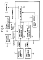
- one preferred control device for the die cushion is capable of suitably switching from the above force control to position control by using a position detector, or vice versa.
- a control device as shown in Fig. 3 has a first speed commanding part 56, for generating a first speed command of the die cushion, based on a position command generated by a position commanding part 52 and a detected result by a position detector 54 for detecting the position of the die cushion.
- the control device 50 also has a second speed commanding part 62, for generating a second speed command of the die cushion, based on a force command generated by a force commanding part 58 and a detected result by a force detector 60 for detecting the pressure between the slide and the die cushion.
- the control device 50 further has a switch judging part 64 for judging that the command for controlling the die cushion should be switched from the first command to the second command, or vice versa, and a switching part 66 for switching the command based on the judgment of the judging part 64.
- the control device 50 may perform a control of the die cushion more preferable than only force control or speed control.
- the control device 50 cannot perform suitable control.
- each die cushion is independently controlled by an individual control device. Therefore, at a certain of time during press machining, there may be a situation in which one die cushion is controlled by position control and the other die cushion is controlled by force control.
- the cushion pad supported by the plurality of die cushions is generally an integral member, an undesired mechanical distortion may occur in the cushion pad due to an excess force applied to the cushion pad. As a result, the accuracy of press machining may be reduced and the press machine may be damaged.
- an object of the present invention is to provide a control system, for a press machine including a plurality of die cushions, by which force control and position control may be suitably switched from one to another in each control device for each of the die cushions.
- a control system including a plurality of control devices for a servo die cushion mechanism including a plurality of die cushions, for generating a force applied to a slide by using a servomotor as a drive source, the control system comprising: a position commanding part for generating a position command of each die cushion; a position detecting part for detecting the position of each die cushion; a force commanding part for generating a force command between the slide and each die cushion; and a force detecting part for detecting a force generated between the slide and each die cushion, wherein each control device comprises: a first speed commanding part for generating a first speed command of each die cushion based on the position command and the position detected by the position detecting part; a second speed commanding part for
- the first and second predetermined numbers may be equal to one.
- the first and second predetermined numbers may be equal to two.
- the first and second predetermined numbers may be equal to half of the number of the control devices.
- the first and second predetermined numbers may be equal to the number of the control devices.
- the first predetermined number may be equal to one and the second predetermined number may be equal to the number of the control devices.
- the first predetermined number may be equal to two and the second predetermined number may be equal to the number of the control devices.
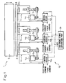
- Fig. 1 shows a schematic configuration of a press machine 1 including a control system 10 for a servo die cushion according to the present invention.
- the press machine 1 has a slide 2 driven by a suitable link mechanism (not shown), a cushion pad 3 capable of moving corresponding to the motion of the slide 2 and a plurality of (three in this case) die cushion mechanisms 4a, 4b and 4c for cooperatively driving the cushion pad 3.
- the positions the die cushions are respectively changed by servomotors 5a, 5b and 5c controlled by control devices 10a, 10b and 10c. In other words, each control device controls the speed of each die cushion.
- the control system 10 has a switching signal generating part 30 configured to receive the judgment result of each control device, to generate a switching signal and to transmit the signal to the control devices for switching the control mode of the die cushions.
- the number of the die cushions of the control devices may be equal to or larger than two. In relation to the application of the invention, there is no difference depending on the number of the die cushions or the control devices.
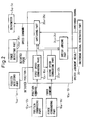
- Fig. 2 shows the detailed constitution of each control device. Only the control device 10a is described in detail below, as the other control devices 10b and 10c may be the same as the control device 10a.
- the control device 10a has a first speed commanding part 16a for generating a first speed command for the die cushion 4a, based on a position command generated by a position commanding part 12a of the die cushion 4a and detected data generated by a position detecting part 14a for detecting the position of the die cushion 4a. Due to this, the control device 10a may generate a speed command for the servomotor 5a based on the position control.
- control device 10a has a second speed commanding part 22a for generating a second speed command for the die cushion 4a, based on a force command generated by a force commanding part 18a of the die cushion 4a and a detected data by a force detecting part 20a for detecting the force between the die cushion 4a and the slide 2. Due to this, the control device 10a may also generate a speed command for the servomotor 5a based on the force control.
- control device 10a has a switch judging part 24a for judging that the command for controlling the die cushion 4a should be switched from the first speed command to the second speed command, or vice versa.
- one of the speed commands is selected such that the press force or the force between the slide 2 and the cushion pad 3 does not excessively increase.
- the control device 10a also has a switching part 26a for switching the first speed command to the second speed command, or vice versa, upon receiving a switching signal from a switching signal generating part 30.
- the control system 10 of the invention includes a switching signal generating part 30 capable of collecting the judgment results of switch judging parts of the control devices 10a, 10b and 10c.
- the major feature of the control system 10 is that each control device 10a, 10b or 10c does not change the control mode of the die cushion upon each judgment result of each switch judging part of each control device is outputted, instead, each judgment result is first transmitted to the switching signal generating part 30 in a suitable form such as a signal and, then, the switching signal generating part 30 generates a switching signal bused on the judgment results the switch judging parts and a predetermined criterion.
- each switching part of each control device switches the control mode of the die cushion from the position control to the force control, or vice versa, upon receiving the switching signal from the switching signal generating part 30.
- the predetermined criterion is either when the number of control devices, in which the switch judging parts judge the command for controlling the die cushions should be switched from the first speed command to the second speed command (i.e., from the position control to the force control), reaches a first predetermined number, or when the number of control devices, in which the switch judging parts judge the command for controlling the die cushions should be switched from the second speed command to the first speed command (i.e., from the force control to the position control), reaches a second predetermined number.
- transmission of the switching signal to each control device and switching action of the control mode of each die cushion are simultaneously performed in all control devices.
- the above first and second predetermined numbers may be set to various suitable values.
- preferable values for the first and second numbers are one, two, half the number of the control devices, and the number of the control devices (or the number of the die cushions).
- the fastest switching action can be performed. This is because control modes of all die cushions are simultaneously switched when only one control device judges that the control mode of corresponding die cushion should be changed.
- the first and second predetermined numbers are equal to two, in addition to the similar effect to the case in which the first and second numbers are equal to one, a risk or a disadvantage, -in case that the first judgment is due to a malfunction or a false detection, may be avoided. This is because it is highly unlikely that a malfunction or a false detection occurs twice in a row.
- the predetermined numbers may be equal to a half of the number of the control devices.
- the "half" may be equal to either (N+1)/2 or (N-1)/2.
- a number near a half of the number of control devices may be used.
- all control devices may simultaneously switch the control mode of corresponding die cushion at a certain point in time. Therefore, unlike a case in which each die cushion is independently controlled, the position control and the force control are not performed at the same time. Due to this, a disadvantage, such as an undesired mechanical distortion in the cushion pad, which may be generated by an excess force applied to the cushion pad, is avoided.
- the first and second predetermined numbers may be different from each other.
- the first number, used for switching the position control to the force control may be set to one or two and, further, the second number, used for switching the force control to the position control, may be set to the number of the control devices.
- switching action from the position control to the force control is quickly performed but, on the other hand, switching action from the force control to the position control is delayed as much as possible. Therefore, a period of time during the force control, which is more suitable than the position control in respect of avoiding an excess increase of the press force, may be extended.
- control system for the servo die cushion of the present invention in controlling a plurality of die cushions by using a plurality of control devices, all control devices switch the control mode of the die cushions when switch judging parts of a predetermined number of control devices judge that the control mode of corresponding die cushion should be switched from position control to force control, or vice versa. Therefore, the position control and the force control are not performed at the same time, whereby an excess force is prevented from being applied to the cushion pad.
Abstract
Description
- The present invention relates to a control system, for a servo die cushion, which generates a force on a slide of a press machine using a servomotor as a drive source.
- It is known that a press machine, for press working such as bending, drawing or punching, can be provided with a die cushion mechanism, as an attached device, for applying a predetermined force or pressure, during the press working, to a movable support member (generally called a slide) supporting a first mold for press working, the force being generated by another movable member supporting a second mold. The die cushion mechanism is generally configured such that the slide (or the first mold), moving in a mold-clamping direction, directly or indirectly collides with a movable element (generally called as a cushion pad) held at a predetermined pressure and, until the molding is finished, the cushion pad is moved with the slide while applying force or pressure to the slide. During this operation, it is possible to prevent the occurrence of wrinkles in a workpiece to be pressed by, for example, clamping an area around a site, of the workpiece to be pressed, between the cushion pad and the slide.
- Many conventional die cushion mechanisms use a hydraulic or a pneumatic unit as a drive source. However, control by a hydraulic or a pneumatic unit may be carried out only under a constant pressure. It is preferable that the pressure during drawing is varied corresponding to the amount of the drawing. However, the pressure cannot be varied in a hydraulic or a pneumatic unit.
- In recent years, therefore, a die cushion mechanism using a servomotor as a drive source has been used to carry out force control at a high speed, as described in Japanese Unexamined Patent Publication (Kokai)
No. 10-202327 - It could be said that one preferred control device for the die cushion is capable of suitably switching from the above force control to position control by using a position detector, or vice versa. For example, a control device as shown in Fig. 3 has a first
speed commanding part 56, for generating a first speed command of the die cushion, based on a position command generated by aposition commanding part 52 and a detected result by aposition detector 54 for detecting the position of the die cushion. Thecontrol device 50 also has a secondspeed commanding part 62, for generating a second speed command of the die cushion, based on a force command generated by aforce commanding part 58 and a detected result by aforce detector 60 for detecting the pressure between the slide and the die cushion. Thecontrol device 50 further has aswitch judging part 64 for judging that the command for controlling the die cushion should be switched from the first command to the second command, or vice versa, and a switchingpart 66 for switching the command based on the judgment of thejudging part 64. - If the number of the die cushion to be controlled is one, the
control device 50 may perform a control of the die cushion more preferable than only force control or speed control. However, when the cushion pad is relatively large and the cushion pad is supported by a plurality of die cushions, thecontrol device 50 cannot perform suitable control. In other words, when a plurality of die cushions are used, each die cushion is independently controlled by an individual control device. Therefore, at a certain of time during press machining, there may be a situation in which one die cushion is controlled by position control and the other die cushion is controlled by force control. In such a situation, as the cushion pad supported by the plurality of die cushions is generally an integral member, an undesired mechanical distortion may occur in the cushion pad due to an excess force applied to the cushion pad. As a result, the accuracy of press machining may be reduced and the press machine may be damaged. - Therefore, an object of the present invention is to provide a control system, for a press machine including a plurality of die cushions, by which force control and position control may be suitably switched from one to another in each control device for each of the die cushions. According to the present invention, there is provided a control system including a plurality of control devices for a servo die cushion mechanism including a plurality of die cushions, for generating a force applied to a slide by using a servomotor as a drive source, the control system comprising: a position commanding part for generating a position command of each die cushion; a position detecting part for detecting the position of each die cushion; a force commanding part for generating a force command between the slide and each die cushion; and a force detecting part for detecting a force generated between the slide and each die cushion, wherein each control device comprises: a first speed commanding part for generating a first speed command of each die cushion based on the position command and the position detected by the position detecting part; a second speed commanding part for generating a second speed command of each die cushion based on the force command and the force detected by the force detecting part; a switch judging part for judging that the command for controlling each die cushion should be switched from the first command to the second command, or vice versa; and a switching part for switching the command based on the judgment of the switch judging part, and wherein the control system further comprises: a switching signal generating part capable of collecting the judgment result of each switch judging part, the switching signal generating part being configured to generate a switching signal and transmit the signal to the switching parts of the plurality of control devices, either when the number of control devices, in which the switch judging parts judge the command for controlling the die cushions should be switched from the first speed command to the second speed command, reaches a first predetermined number, or when the number of control devices, in which the switch judging parts judge the command for controlling the die cushions should be switched from the second speed command to the first speed command, reaches a second predetermined number.
- Concretely, the first and second predetermined numbers may be equal to one.
- Alternatively, the first and second predetermined numbers may be equal to two.
- Alternatively, the first and second predetermined numbers may be equal to half of the number of the control devices.
- Alternatively, the first and second predetermined numbers may be equal to the number of the control devices.
- Alternatively the first predetermined number may be equal to one and the second predetermined number may be equal to the number of the control devices.
- Alternatively, the first predetermined number may be equal to two and the second predetermined number may be equal to the number of the control devices.
- The above and other objects, features and advantages of the present invention will be made more apparent by the following description of the preferred embodiments thereof, with reference to the accompanying drawings, wherein:
- Fig. 1 shows a schematic configuration of a press machine including a control system for a servo die cushion according to the present invention;
- Fig. 2 shows the detailed constitution of each control device shown in Fig. 1; and
- Fig. 3 shows an example of the constitution of a control device for individually controlling each die cushion.
- The present invention is explained below with reference to the drawings.
- Fig. 1 shows a schematic configuration of a press machine 1 including a
control system 10 for a servo die cushion according to the present invention. The press machine 1 has a slide 2 driven by a suitable link mechanism (not shown), acushion pad 3 capable of moving corresponding to the motion of the slide 2 and a plurality of (three in this case)die cushion mechanisms 4a, 4b and 4c for cooperatively driving thecushion pad 3. The positions the die cushions are respectively changed byservomotors control devices control system 10 has a switchingsignal generating part 30 configured to receive the judgment result of each control device, to generate a switching signal and to transmit the signal to the control devices for switching the control mode of the die cushions. The number of the die cushions of the control devices may be equal to or larger than two. In relation to the application of the invention, there is no difference depending on the number of the die cushions or the control devices. - Fig. 2 shows the detailed constitution of each control device. Only the
control device 10a is described in detail below, as theother control devices control device 10a. Thecontrol device 10a has a firstspeed commanding part 16a for generating a first speed command for thedie cushion 4a, based on a position command generated by a position commanding part 12a of thedie cushion 4a and detected data generated by aposition detecting part 14a for detecting the position of thedie cushion 4a. Due to this, thecontrol device 10a may generate a speed command for theservomotor 5a based on the position control. Also, thecontrol device 10a has a secondspeed commanding part 22a for generating a second speed command for thedie cushion 4a, based on a force command generated by aforce commanding part 18a of thedie cushion 4a and a detected data by aforce detecting part 20a for detecting the force between thedie cushion 4a and the slide 2. Due to this, thecontrol device 10a may also generate a speed command for theservomotor 5a based on the force control. - Further, the
control device 10a has aswitch judging part 24a for judging that the command for controlling thedie cushion 4a should be switched from the first speed command to the second speed command, or vice versa. At this point, it is preferable that one of the speed commands is selected such that the press force or the force between the slide 2 and thecushion pad 3 does not excessively increase. For example, by comparing the position control with the force control, one of the control modes, in which thedie cushion 4a is downwardly moved longer (i.e., farther away from the slide 2), may be selected for controlling the die cushion. Thecontrol device 10a also has aswitching part 26a for switching the first speed command to the second speed command, or vice versa, upon receiving a switching signal from a switchingsignal generating part 30. - As shown, the
control system 10 of the invention includes a switchingsignal generating part 30 capable of collecting the judgment results of switch judging parts of thecontrol devices control system 10 is that eachcontrol device signal generating part 30 in a suitable form such as a signal and, then, the switchingsignal generating part 30 generates a switching signal bused on the judgment results the switch judging parts and a predetermined criterion. Subsequently, each switching part of each control device switches the control mode of the die cushion from the position control to the force control, or vice versa, upon receiving the switching signal from the switchingsignal generating part 30. For example, the predetermined criterion is either when the number of control devices, in which the switch judging parts judge the command for controlling the die cushions should be switched from the first speed command to the second speed command (i.e., from the position control to the force control), reaches a first predetermined number, or when the number of control devices, in which the switch judging parts judge the command for controlling the die cushions should be switched from the second speed command to the first speed command (i.e., from the force control to the position control), reaches a second predetermined number. At this point, it is preferable that transmission of the switching signal to each control device and switching action of the control mode of each die cushion are simultaneously performed in all control devices. - The above first and second predetermined numbers may be set to various suitable values. For example, preferable values for the first and second numbers are one, two, half the number of the control devices, and the number of the control devices (or the number of the die cushions). When the first and second predetermined numbers are equal to one, the fastest switching action can be performed. This is because control modes of all die cushions are simultaneously switched when only one control device judges that the control mode of corresponding die cushion should be changed. When the first and second predetermined numbers are equal to two, in addition to the similar effect to the case in which the first and second numbers are equal to one, a risk or a disadvantage, -in case that the first judgment is due to a malfunction or a false detection, may be avoided. This is because it is highly unlikely that a malfunction or a false detection occurs twice in a row.
- If the number of the control devices is very high and switching action of the control mode should be somewhat delayed, the predetermined numbers may be equal to a half of the number of the control devices. When the number of control devices is an odd number N, the "half" may be equal to either (N+1)/2 or (N-1)/2. Also, a number near a half of the number of control devices may be used.
- When the first and second predetermined numbers are set to the number of the control devices, switching action is not performed until all switch judging parts of the control devices judge that the control mode of each die cushion should be changed. Therefore, this method is suitable when switching of the control mode is desired to be delayed as much as possible.
- In any predetermined number, all control devices may simultaneously switch the control mode of corresponding die cushion at a certain point in time. Therefore, unlike a case in which each die cushion is independently controlled, the position control and the force control are not performed at the same time. Due to this, a disadvantage, such as an undesired mechanical distortion in the cushion pad, which may be generated by an excess force applied to the cushion pad, is avoided.
- The first and second predetermined numbers may be different from each other. For example, the first number, used for switching the position control to the force control, may be set to one or two and, further, the second number, used for switching the force control to the position control, may be set to the number of the control devices. In this case, switching action from the position control to the force control is quickly performed but, on the other hand, switching action from the force control to the position control is delayed as much as possible. Therefore, a period of time during the force control, which is more suitable than the position control in respect of avoiding an excess increase of the press force, may be extended.
- According to the control system for the servo die cushion of the present invention, in controlling a plurality of die cushions by using a plurality of control devices, all control devices switch the control mode of the die cushions when switch judging parts of a predetermined number of control devices judge that the control mode of corresponding die cushion should be switched from position control to force control, or vice versa. Therefore, the position control and the force control are not performed at the same time, whereby an excess force is prevented from being applied to the cushion pad.
- While the invention has been described with reference to specific embodiments chosen for the purpose of illustration, it should be apparent that numerous modifications could be made thereto, by one skilled in the art, without departing from the basic concept and scope of the invention.
Claims (7)
- A control system (10) including a plurality of control devices (10a, 10b, 10c) for a servo die cushion mechanism including a plurality of die cushions (4a, 4b, 4c), for generating a force applied to a slide (2) by using a servomotor (5a, 5b, 5c) as a drive source, the control system comprising:a position commanding part (12a, 12b, 12c) for generating a position command of each die cushion;a position detecting part (14a, 14b, 14c) for detecting the position of each die cushion;a force commanding part (18a, 18b, 18c) for generating a force command between the slide and each die cushion; anda force detecting part (20a, 20b, 20c) for detecting a force generated between the slide and each die cushion,
characterized in that each control device (10a, 10b, 10c) comprises:a first speed commanding part (16a, 16b, 16c) for generating a first speed command of each die cushion based on the position command and the position detected by the position detecting part (14a, 14b, 14c);a second speed commanding part (22a, 22b, 22c) for generating a second speed command of each die cushion based on the force command and the force detected by the force detecting part (20a, 20b, 20c);a switch judging part (24a, 24b, 24c) for judging that the command for controlling each die cushion should be switched from the first command to the second command, or vice versa; anda switching part (26a, 26b, 26c) for switching the command based on the judgment of the switch judging part (24a, 24b, 24c),and characterized in that the control system further comprises:a switching signal generating part (30) capable of collecting the judgment result of each switch judging part (24a, 24b, 24c), the switching signal generating part being configured to generate a switching signal and transmit the signal to the switching parts (26a, 26b, 26c) of the plurality of control devices (10a, 10b, 10c), either when the number of control devices, in which the switch judging parts (24a, 29b, 24c) judge the command for controlling the die cushions (4a, 4b, 4c) should be switched from the first speed command to the second speed command, reaches a first predetermined number, or when the number of control devices, in which the switch judging parts (24a, 24b, 24c) judge the command for controlling the die cushions (4a, 4b, 4c) should be switched from the second speed command to the first speed command, reaches a second predetermined number. - The control system as set forth in claim 1, wherein the first and second predetermined numbers are equal to one.
- The control system as set forth in claim 1, wherein the first and second predetermined numbers are equal to two.
- The control system as set forth in claim 1, wherein the first and second predetermined numbers are equal to half of the number of the control devices (10a, 10b, 10c).
- The control system as set forth in claim 1, wherein the first and second predetermined numbers are equal to the number of the control devices (10a, 10b, 10c).
- The control system as set forth in claim 1, wherein the first predetermined number is equal to one and the second predetermined number is equal to the number of the control devices (10a, 10b, 10c).
- The control system as set forth in claim 1, wherein the first predetermined number is equal to two and the second predetermined number is equal to the number of the control devices (10a, 10b, 10c).
Applications Claiming Priority (1)
| Application Number | Priority Date | Filing Date | Title |
|---|---|---|---|
| JP2005201225A JP4041508B2 (en) | 2005-07-11 | 2005-07-11 | Servo die cushion control device |
Publications (3)
| Publication Number | Publication Date |
|---|---|
| EP1743718A2 true EP1743718A2 (en) | 2007-01-17 |
| EP1743718A3 EP1743718A3 (en) | 2009-04-15 |
| EP1743718B1 EP1743718B1 (en) | 2012-12-12 |
Family
ID=37025218
Family Applications (1)
| Application Number | Title | Priority Date | Filing Date |
|---|---|---|---|
| EP06014041A Active EP1743718B1 (en) | 2005-07-11 | 2006-07-06 | Control system for servo die cushion |
Country Status (4)
| Country | Link |
|---|---|
| US (1) | US7392684B2 (en) |
| EP (1) | EP1743718B1 (en) |
| JP (1) | JP4041508B2 (en) |
| CN (1) | CN100475378C (en) |
Cited By (3)
| Publication number | Priority date | Publication date | Assignee | Title |
|---|---|---|---|---|
| EP2813358A1 (en) * | 2013-06-14 | 2014-12-17 | Aida Engineering, Ltd. | Die cushion force setting apparatus |
| EP2734023A4 (en) * | 2011-07-11 | 2015-05-13 | Fuji Machine Mfg | Manufacturing machine |
| WO2019042721A1 (en) * | 2017-09-04 | 2019-03-07 | Bayerische Motoren Werke Aktiengesellschaft | Method for operating a forming press |
Families Citing this family (11)
| Publication number | Priority date | Publication date | Assignee | Title |
|---|---|---|---|---|
| JP4233514B2 (en) * | 2004-11-04 | 2009-03-04 | ファナック株式会社 | Die cushion mechanism, control device and control method thereof |
| JP4080504B2 (en) * | 2005-10-18 | 2008-04-23 | ファナック株式会社 | Die cushion control device |
| JP4174543B2 (en) * | 2007-01-29 | 2008-11-05 | ファナック株式会社 | Servo motor control device |
| US8943936B2 (en) * | 2007-03-13 | 2015-02-03 | Moran BORENSTEIN | Method and apparatus for forming a sheet of foil |
| JP5296415B2 (en) * | 2008-05-22 | 2013-09-25 | 株式会社小松製作所 | Die cushion device |
| CN101620436A (en) * | 2008-07-04 | 2010-01-06 | 鸿富锦精密工业(深圳)有限公司 | Control device and control method of speed controlling after interpolation |
| US20120227452A1 (en) * | 2011-03-07 | 2012-09-13 | Toyota Motor Engineering & Manufacturing North America, Inc. | Method and system for controlling the quality of a stamped part |
| JP5951591B2 (en) * | 2013-12-26 | 2016-07-13 | アイダエンジニアリング株式会社 | Die cushion force control method and die cushion device |
| JP6059291B2 (en) * | 2015-06-03 | 2017-01-11 | アイダエンジニアリング株式会社 | Die cushion device for press machine |
| JP6851837B2 (en) * | 2017-01-20 | 2021-03-31 | キヤノン株式会社 | Manufacturing methods for control devices, robot systems, control methods, programs, recording media and articles |
| JP7381294B2 (en) | 2019-10-30 | 2023-11-15 | ファナック株式会社 | A control device for a processing machine that processes a workpiece on a die cushion. |
Citations (1)
| Publication number | Priority date | Publication date | Assignee | Title |
|---|---|---|---|---|
| JP2004276028A (en) | 2003-01-21 | 2004-10-07 | Hoden Seimitsu Kako Kenkyusho Ltd | Press machine |
Family Cites Families (4)
| Publication number | Priority date | Publication date | Assignee | Title |
|---|---|---|---|---|
| JPS6224991A (en) * | 1985-07-26 | 1987-02-02 | 松下電器産業株式会社 | Industrial robot |
| US5435166A (en) * | 1991-07-01 | 1995-07-25 | Kabushiki Kaisha Komatsu Seisakusho | Die cushion device for press |
| JPH10202327A (en) * | 1997-01-22 | 1998-08-04 | Aida Eng Ltd | Die cushion controller of press |
| JP3853908B2 (en) * | 1997-03-31 | 2006-12-06 | 株式会社小松製作所 | Multi-point servo press controller |
-
2005
- 2005-07-11 JP JP2005201225A patent/JP4041508B2/en active Active
-
2006
- 2006-07-06 EP EP06014041A patent/EP1743718B1/en active Active
- 2006-07-10 CN CNB2006101017804A patent/CN100475378C/en active Active
- 2006-07-10 US US11/456,507 patent/US7392684B2/en active Active
Patent Citations (1)
| Publication number | Priority date | Publication date | Assignee | Title |
|---|---|---|---|---|
| JP2004276028A (en) | 2003-01-21 | 2004-10-07 | Hoden Seimitsu Kako Kenkyusho Ltd | Press machine |
Cited By (5)
| Publication number | Priority date | Publication date | Assignee | Title |
|---|---|---|---|---|
| EP2734023A4 (en) * | 2011-07-11 | 2015-05-13 | Fuji Machine Mfg | Manufacturing machine |
| EP2813358A1 (en) * | 2013-06-14 | 2014-12-17 | Aida Engineering, Ltd. | Die cushion force setting apparatus |
| US9669446B2 (en) | 2013-06-14 | 2017-06-06 | Aida Engineering, Ltd. | Die cushion force setting apparatus |
| WO2019042721A1 (en) * | 2017-09-04 | 2019-03-07 | Bayerische Motoren Werke Aktiengesellschaft | Method for operating a forming press |
| US11524326B2 (en) | 2017-09-04 | 2022-12-13 | Bayerische Motoren Werke Aktiengesellschaft | Method for operating a forming press |
Also Published As
| Publication number | Publication date |
|---|---|
| CN100475378C (en) | 2009-04-08 |
| US20070006630A1 (en) | 2007-01-11 |
| JP2007015007A (en) | 2007-01-25 |
| US7392684B2 (en) | 2008-07-01 |
| JP4041508B2 (en) | 2008-01-30 |
| EP1743718A3 (en) | 2009-04-15 |
| EP1743718B1 (en) | 2012-12-12 |
| CN1895806A (en) | 2007-01-17 |
Similar Documents
| Publication | Publication Date | Title |
|---|---|---|
| EP1743718A2 (en) | Control system for servo die cushion | |
| US7331208B2 (en) | Die cushion controller | |
| EP1887445B1 (en) | Numerical controller | |
| US7293447B2 (en) | Control device for die cushion mechanism | |
| US20090230910A1 (en) | Numerical controller having function to switch between pressure control and position control | |
| US7923956B2 (en) | Control device for servo die cushion | |
| US7421878B2 (en) | Control device for servo die cushion | |
| US7360391B2 (en) | Control device for servo die cushion | |
| US20080245121A1 (en) | Device for judging collision of a die cushion mechanism and system for judging collision | |
| CN1768977B (en) | Die cushion mechanism, and control device and control method therefor | |
| US7685860B2 (en) | Control device for press machine | |
| EP1898284B1 (en) | Control device for servo die cushion | |
| JP2008200756A (en) | Die cushion mechanism, and device and method for controlling the same |
Legal Events
| Date | Code | Title | Description |
|---|---|---|---|
| PUAI | Public reference made under article 153(3) epc to a published international application that has entered the european phase |
Free format text: ORIGINAL CODE: 0009012 |
|
| AK | Designated contracting states |
Kind code of ref document: A2 Designated state(s): AT BE BG CH CY CZ DE DK EE ES FI FR GB GR HU IE IS IT LI LT LU LV MC NL PL PT RO SE SI SK TR |
|
| AX | Request for extension of the european patent |
Extension state: AL BA HR MK YU |
|
| PUAL | Search report despatched |
Free format text: ORIGINAL CODE: 0009013 |
|
| AK | Designated contracting states |
Kind code of ref document: A3 Designated state(s): AT BE BG CH CY CZ DE DK EE ES FI FR GB GR HU IE IS IT LI LT LU LV MC NL PL PT RO SE SI SK TR |
|
| AX | Request for extension of the european patent |
Extension state: AL BA HR MK RS |
|
| 17P | Request for examination filed |
Effective date: 20090624 |
|
| 17Q | First examination report despatched |
Effective date: 20090724 |
|
| AKX | Designation fees paid |
Designated state(s): DE |
|
| RAP1 | Party data changed (applicant data changed or rights of an application transferred) |
Owner name: FANUC CORPORATION |
|
| REG | Reference to a national code |
Ref country code: DE Ref legal event code: R079 Ref document number: 602006033548 Country of ref document: DE Free format text: PREVIOUS MAIN CLASS: B21D0024020000 Ipc: G05B0019190000 |
|
| RIC1 | Information provided on ipc code assigned before grant |
Ipc: G05B 19/19 20060101AFI20120521BHEP Ipc: B21D 24/02 20060101ALI20120521BHEP |
|
| GRAP | Despatch of communication of intention to grant a patent |
Free format text: ORIGINAL CODE: EPIDOSNIGR1 |
|
| GRAS | Grant fee paid |
Free format text: ORIGINAL CODE: EPIDOSNIGR3 |
|
| GRAA | (expected) grant |
Free format text: ORIGINAL CODE: 0009210 |
|
| AK | Designated contracting states |
Kind code of ref document: B1 Designated state(s): DE |
|
| REG | Reference to a national code |
Ref country code: DE Ref legal event code: R096 Ref document number: 602006033548 Country of ref document: DE Effective date: 20130207 |
|
| PLBE | No opposition filed within time limit |
Free format text: ORIGINAL CODE: 0009261 |
|
| STAA | Information on the status of an ep patent application or granted ep patent |
Free format text: STATUS: NO OPPOSITION FILED WITHIN TIME LIMIT |
|
| 26N | No opposition filed |
Effective date: 20130913 |
|
| REG | Reference to a national code |
Ref country code: DE Ref legal event code: R097 Ref document number: 602006033548 Country of ref document: DE Effective date: 20130913 |
|
| PGFP | Annual fee paid to national office [announced via postgrant information from national office to epo] |
Ref country code: DE Payment date: 20230531 Year of fee payment: 18 |