EP1742302A1 - A connector, connector assembly and assembling method therefor - Google Patents
A connector, connector assembly and assembling method therefor Download PDFInfo
- Publication number
- EP1742302A1 EP1742302A1 EP06013400A EP06013400A EP1742302A1 EP 1742302 A1 EP1742302 A1 EP 1742302A1 EP 06013400 A EP06013400 A EP 06013400A EP 06013400 A EP06013400 A EP 06013400A EP 1742302 A1 EP1742302 A1 EP 1742302A1
- Authority
- EP
- European Patent Office
- Prior art keywords
- locking claw
- housing
- movable member
- engaging portion
- standby position
- Prior art date
- Legal status (The legal status is an assumption and is not a legal conclusion. Google has not performed a legal analysis and makes no representation as to the accuracy of the status listed.)
- Granted
Links
Images






Classifications
-
- H—ELECTRICITY
- H01—ELECTRIC ELEMENTS
- H01R—ELECTRICALLY-CONDUCTIVE CONNECTIONS; STRUCTURAL ASSOCIATIONS OF A PLURALITY OF MUTUALLY-INSULATED ELECTRICAL CONNECTING ELEMENTS; COUPLING DEVICES; CURRENT COLLECTORS
- H01R13/00—Details of coupling devices of the kinds covered by groups H01R12/70 or H01R24/00 - H01R33/00
- H01R13/62—Means for facilitating engagement or disengagement of coupling parts or for holding them in engagement
- H01R13/629—Additional means for facilitating engagement or disengagement of coupling parts, e.g. aligning or guiding means, levers, gas pressure electrical locking indicators, manufacturing tolerances
- H01R13/62933—Comprising exclusively pivoting lever
- H01R13/62938—Pivoting lever comprising own camming means
-
- H—ELECTRICITY
- H01—ELECTRIC ELEMENTS
- H01R—ELECTRICALLY-CONDUCTIVE CONNECTIONS; STRUCTURAL ASSOCIATIONS OF A PLURALITY OF MUTUALLY-INSULATED ELECTRICAL CONNECTING ELEMENTS; COUPLING DEVICES; CURRENT COLLECTORS
- H01R13/00—Details of coupling devices of the kinds covered by groups H01R12/70 or H01R24/00 - H01R33/00
- H01R13/62—Means for facilitating engagement or disengagement of coupling parts or for holding them in engagement
- H01R13/629—Additional means for facilitating engagement or disengagement of coupling parts, e.g. aligning or guiding means, levers, gas pressure electrical locking indicators, manufacturing tolerances
- H01R13/62933—Comprising exclusively pivoting lever
- H01R13/62955—Pivoting lever comprising supplementary/additional locking means
Definitions
- the present invention relates to a connector of the movable member type, preferably to a lever-type connector, to a connector assembly and to an assembling method therefor.
- a lever-type connector is known e.g. from Japanese Unexamined Patent Publication No. 2004-319125 .
- This connector is constructed such that a lever having a cam groove formed in an arm portion thereof is rotatably mounted on the first housing, and a cam follower formed on a second housing is guided along the cam groove by rotating the lever from a standby position to a connection position, thereby connecting the first and second housings. If an attempt is made to rotate the lever before an connecting operation of the first and second housings with the lever located at the standby position, a cantilever-shaped resilient locking piece formed on the arm portion of the lever comes into contact with a notched groove formed in an outer wall of the first housing, whereby a rotation of the lever toward the connection position is prevented.
- an end edge of the notched groove becomes, in some cases, a free end resiliently deformable along the thickness direction of the outer wall. If the resilient locking piece is engageable with the free edge of the notched groove, the free end of the notched groove in contact with the locking piece is turned up, thereby undergoing such a resilient deformation as to move onto the locking piece. Therefore, there is a possibility of being unable to obtain a sufficient holding force between the resilient locking piece and the notched groove.
- the present invention was developed in view of the above problem and an object thereof is to provide for an increased holding force upon holding a movable member on or in a housing at a standby position.
- a connector comprising:
- a lever-type connector comprising:
- the contact surface is formed with a slanted or rounded surface for exerting such a force acting in a direction opposite to the unlocking direction of the locking claw to the locking claw when the contact surface comes substantially into contact with the engaging portion.
- the contact surface is formed with such a slanted or rounded surface as to exert a force acting in the direction opposite to the unlocking direction of the locking claw to the locking claw when the contact surface comes substantially into contact with the engaging portion.
- the second or mating housing includes at least one restriction lifting portion for resiliently deforming the locking claw substantially in the unlocking direction to disengage the locking claw from the engaging portion by coming into contact with the locking claw when the two housings are lightly fitted to each other with the movable member, preferably the lever located at the standby position.
- the locking claw and the engaging portion can be disengaged from each other by the restriction lifting portion by lightly fitting the first and second housings to each other.
- operation efficiency in the process of connecting the two housings can be improved as compared to a case where a separate step of disengaging the locking claw and the engaging portion is necessary.
- the movable member is made of a synthetic resin
- the locking claw is formed inside a slit made in the side plate and formed by a mold openable and closable along the thickness direction of the locking claw.
- the slanted surface is displaced from the deformation preventing portion in the width direction of the locking claw.
- the lever is made of a synthetic resin
- the locking claw is formed inside a slit made in the side plate and formed by a mold openable and closable along the thickness direction of the locking claw, and the slanted surface is displaced from the turn-up preventing portion in the width direction of the locking claw.
- the locking claw is arranged inside the movement path of the movable member, preferably inside the rotation path of the lever, since being formed inside the slit made in the side plate. This can prevent the enlargement of the movement path of the movable member, preferably of the rotation path of the lever, and also the enlargement of the (first) housing.
- the movable member preferably the lever
- the movable member is formed using a mold openable and closable along the thickness direction of the locking claw
- no spaces used to remove mold parts for forming the turn-up preventing portion and the slanted surface can be ensured since the locking claw is surrounded by the side plate if the deformation or turn-up preventing portion and the slanted surface are so arranged as to overlap in the thickness direction of the locking claw. Therefore, there is a possibility of being unable to form the deformation or turn-up preventing portion and the slanted surface.
- the deformation or turned-up preventing portion and the slanted surface are displaced in the width direction of the locking claw. Therefore, the deformation or turn-up preventing portion and the slanted surface can be formed even in the case of using a mold openable and closable along the thickness direction of the locking claw.
- the operating direction of the movable member at the standby position is set to be a direction substantially opposite to the connecting direction of the two housings.
- a connector assembly comprising a connector according to the invention or a preferred embodiment thereof and a mating connector connectable therewith, wherein the housing of the connector being connectable with the mating housing of the mating connector and the connection of the housings is performed or assisted by the operation of the movable member provided in or on the connector.
- the mating housing includes at least one restriction lifting portion for resiliently deforming the locking claw in the unlocking direction to disengage the locking claw from the engaging portion by coming substantially into contact with the locking claw when the two housings are lightly fitted to each other with the movable member located at the standby position.
- the method further comprises a step of exerting by means of a slanted or rounded surface of the contact surface such a force acting in a direction opposite to the unlocking direction of the locking claw to the locking claw when the contact surface comes into contact with the engaging portion.
- the movable member at the standby position in a direction substantially opposite to the connecting direction of the two housings.
- a connector of the movable member type preferably a lever-type connector according to this embodiment is provided with a female housing 10 (corresponding to a preferred first housing), a lever 11 as a preferred movable member movably (preferably rotatably or pivotably) mounted in or on the female housing 10, and a male housing 12 (corresponding to a preferred second housing) connectable with the female housing 10 through the operation of the movable member (preferably though rotation or pivotal movement of the lever 11) or the connection of the housings 10, 12 is assisted by the operation of the operable member 11.
- connecting directions CD of the two housings 10, 12 are referred to as forward directions.
- the male housing 12 is made e.g. of a synthetic resin and provided with a receptacle 13 having an open front side.
- One or more male terminal fittings 14 substantially in the form of narrow and long bars are arranged at the back wall of the receptacle 13 while penetrating through this back wall substantially in forward and backward directions, and end portions of the male terminal fittings 14 at one side project into the receptacle 13.
- One or more substantially cylindrical cam pins 15 are formed to project laterally (upward and/or downward) at a widthwise intermediate position (preferably near the widthwise centers) of one or more lateral surfaces (preferably the top and/or bottom surfaces) of the receptacle 13.
- One or more restriction lifting portions 16 extending substantially in forward and backward directions FBD (or substantially along the connecting direction CD) and projecting in vertical direction (or in a direction at an angle different from 0° or 180°, preferably substantially normal to the connecting direction CD) are formed at the (preferably substantially opposite) lateral (left and/or right) side(s) of each cam pin 15, and function to resiliently deform a locking claw 17 to be described later in an unlocking direction UD by coming into engagement therewith during a connecting operation of the two housings 10, 12, thereby disengaging the locking claw 17 from an engaging portion 18 to be described later.
- One or more slanted or rounded surfaces 19 are formed at or near the front ends of the restriction lifting portions 16 to facilitate an upward or deflecting movement of the locking claw 17.
- the female housing 10 is made e.g. of a synthetic resin and preferably provided with an outer tube portion 20 and an inner tube portion 21 formed inside the outer tube portion 20.
- a space between the outer tube portion 20 and the inner tube portion 21 serves as a receptacle fitting space 22 into which the receptacle 13 of the male housing 12 is at least partly fittable during the connecting operation of the two housings 10, 12.
- One or more lever accommodating spaces 23 are formed at inner lateral (upper and/or lower) side(s) of the outer tube portion 20 to at least partly penetrate the outer tube portion 20 substantially in forward and backward directions FBD, and the lever 11 is or may be at least partly accommodated in these spaces 23.
- a substantially cylindrical supporting shaft 24 extends downward or inwardly from the inner outer (upper) surface of the lateral (upper) lever accommodating space 23, whereas a substantially cylindrical supporting shaft 24 extends upward or inwardly from the outer (inner) lateral (bottom) surface of the other lateral (lower) lever accommodating space 23.
- a (preferably substantially rectangular) cut-out portion 25 is formed to extend substantially backward from the front edge at a widthwise intermediate position (preferably near or at the widthwise center) of each of the inner (bottom) wall of the lateral (upper) lever accommodating space 23 and the inner (upper) wall of the other lateral (lower) lever accommodating space 23.
- Each cut-out portion 25 has a width slightly larger than a spacing between the restriction lifting portions 16 at its front side and is narrowed with steps to have the substantially same width as the spacing between the restriction lifting portions 16 at an intermediate position (preferably at a position slightly behind a middle part) thereof with respect to depth direction, and the back end thereof is closed.
- One or more stepped portions of the cut-out portion 25 are rounded or slanted and serve as the engaging portions 18.
- the respective engaging portions 18 are formed at the free end edge or front portion of the lateral (upper and/or bottom) wall of the lever accommodating space 23 and are resiliently deformable along the thickness direction TD (or in a direction at an angle different from 0° or 180°, preferably substantially normal to a relative direction of the lever 11 with respect to the housing 10) of the upper and/or bottom wall of the lever accommodating space 23.
- Each female terminal fitting 28 is comprised of a wire connection portion (preferably comprising a barrel portion 30) to be connected (preferably crimped or bent or folded into connection) with the wire 27, and a (preferably substantially rectangular) tube portion 31 formed before or adjacent to the barrel portion 30.
- the male terminal fitting 14 is to be at least partly inserted into this (rectangular) tube portion 31 to establish an electrical connection between the male terminal fitting 14 and the female terminal fitting 28.
- a (preferably substantially cantilever-shaped) locking portion 32 preferably extending substantially forward is formed at an inner wall of each cavity 29 and engageable with the (rectangular) tube portion 31 to retain the female terminal fitting 28.
- An accommodating recess 33 communicating with the rear ends or rear end portions of the cavities 29 is formed at the rear end of the inner tube portion 21, and preferably a resilient plug (such as a one-piece rubber plug 34) is or may be at least partly accommodated in this accommodating recess 33.
- This one-piece rubber plug 34 preferably is in the form of a thick plate and formed with one or more plug-side insertion holes 35 penetrating the plug 34 substantially in forward and backward directions FBD to permit the passage of the wires 27.
- a resilient-plug holder or rubber-plug holder 36 is to be preferably arranged behind the one-piece rubber plug 34 and held in the inner tube portion 21 by the engagement of one or more locking projections 37 projecting outward from the outer surface of the rubber-plug holder 36 with one or more respective receiving portions 38 formed at positions of the inner tube portion 21 near the rear end.
- the rubber-plug holder 36 is formed with one or more holder-side insertion holes 39 penetrating the rubber-plug holder 36 substantially in forward and backward directions FBD to permit the passage of the wires 27, and the inserted wires 27 are drawn out preferably substantially backward.
- a wire cover 40 preferably is to be mounted at or on the rear side of the female housing 10.
- the wire cover 40 is made e.g. of a synthetic resin and substantially has a box shape with an opening extending over the front surface and a lateral end surface (left end surface in FIG. 1).
- a closed substantially opposite side is slanted to form an escaping surface 41.
- one or more, preferably a pair of resilient locking legs 42 project from the front edges of both side plates preferably in such a manner as to substantially face each other.
- one or more, preferably a pair of lateral (upper and/or lower) protrusions 43 are formed at each of the lateral (left and/or right) ends of the lateral (top and/or bottom) surfaces which are longer sides.
- the wire cover 40 preferably is to be so attached as to at least partly cover the rear surface of the female housing 10, and mounted in such a posture that the open end surface 44 faces laterally, e.g. leftward (see FIG. 1) by the engagement of the pair of resilient locking legs 42 with the pair of protrusions 43 arranged at either left or right side.
- the wires 27 drawn out from the rear surface of the female housing 10 are or may be bent sideways at an angle different from 0° or 180°, preferably substantially at 90° after being bundled, and let out to left through the open end surface 44.
- the lever 11 (as the preferred movable member) is made e.g. of a synthetic resin and is substantially gate-shaped by coupling (preferably substantially rectangular) arm portions 46 extending laterally (rightward in FIG. 1) from the outer peripheries of a pair of substantially round side plates 45 by an operable portion 47 (see FIG. 11).
- This lever 11 is formed by a mold (not shown) openable and closable along the thickness direction of the side plates 45.
- the lever 11 is at least partly inserted or accommodated into the lever accommodating spaces 23 of the female housing 10 from an inserting side, preferably from behind, such that both side plates 45 hold the female housing 10 therebetween, and is movably (rotatably or pivotably) mounted between the standby position SP and the connection position CP substantially about the supporting shafts 24 by at least partly fitting the supporting shafts 24 into the shaft holes 48.
- the standby position SP is a position of the lever 11 where the entrances of the cam grooves 49 and the cam pins 15 substantially face each other and the entrance of the cam pins 15 into the cam grooves 49 is permitted (see FIG. 1)
- the connection position CP is a position of the lever 11 where the two housings 10, 12 are substantially completely connected (see FIG. 13).
- the operable portion 47 When the lever 11 is moved in the operating direction OD (e.g. rotated or pivoted in counterclockwise direction) from the standby position SP shown in FIG. 1 to the connection position CP shown in FIG. 13, the operable portion 47 preferably comes into contact with the rear surface of the wire cover 40, thereby preventing any further counterclockwise rotation.
- the operable portion 47 is provided with at least one resiliently deformable locking piece 50, and a locking projection 51 is formed on the rear surface of the wire cover 40 at a position substantially corresponding to the locking piece 50.
- the locking piece 50 is resiliently engaged with the locking projection 51 to lock the lever 11, thereby preventing a movement towards the standby position SP (i.e. a clockwise rotation in FIG. 13) or preventing a movement in a direction substantially opposite to the operating direction OD.
- each side plate 45 is provided with the locking claw 17 engageable with the engaging portion 18 of the aforementioned female housing 10 preferably at a position at a side of or adjacent to the shaft hole 48 substantially opposite to the end of the cam groove 49.
- the locking claw 17 preferably is formed inside a substantially U-shaped slit 52 made in the side plate 45, and has a substantially narrow and long shape substantially in forward and backward directions.
- the locking claw 17 is resiliently deformable along the thickness direction LTD of the side plate 45 (or in the unlocking direction UD) with the base end thereof as a fixed end.
- the inner surface of the locking claw 17 is formed to project from the inner surface of the side plate 45, and normally projects inward from the inner surface of the side plate 45 (see FIG. 11).
- a contact surface 53 that can come substantially into contact with the aforementioned engaging portion 18 is formed at a lateral-inner (right-lower) side of the leading end of the locking claw 17 in FIG. 7.
- This contact surface 53 is formed with such a slanted or rounded surface 54 as to exert a force acting in a direction (downward direction in FIG. 12(a)) substantially opposite to an unlocking direction UD (upward direction in FIG. 12(a)) of the locking claw 17 to the locking claw 17 when the contact surface 53 comes substantially into contact with the engaging portion 18.
- the slanted surface 54 is inclined or rounded obliquely downward to right in FIG. 12(a).
- a turn-up preventing portion 55 for pressing the engaging portion 18 in a direction opposite to the unlocking direction UD of the locking claw 17 to prevent the engaging portion 18 from being turned up and undergoing such a resilient deformation as to move onto the slanted surface 54 when the contact surface 53 and the engaging portion 18 come substantially into contact is formed preferably to project substantially away from the side where the cam groove 49 opens (backward in FIG. 7).
- the lever 11 can be formed even using a mold openable and closable along the thickness direction of the locking claw 17.
- a movement or rotation path of the lever 11 from the standby position SP to the connection position CP is set in the substantially same direction as the one in which the contact surfaces 53 comes into contact with the engaging portions 18.
- the restricting lifting portions 16 formed on the male housing 12 come substantially into contact with the locking claws 17 from the inner side, thereby resiliently deforming the locking claws 17 in the unlocking direction UD or outward of the female housing 10 (see FIG. 12(b)).
- the locking claws 17 slide substantially on the inner surfaces of the inner (bottom) wall of the lateral (upper) lever accommodating space 23 and the inner (upper) wall of the other lateral (lower) lever accommodating space 23 as the lever 11 is operated or rotated, whereby the lever 11 is displaced in the operating direction OD towards or to the connection position CP.
- the wire cover 40 preferably is mounted on the rear surface of the female housing 10. If it is desired to let the wires 27 out laterally (leftward when viewed from front), the wire cover 40 is mounted in such a posture that the open end surface 44 faces laterally (leftward as shown in FIG. 2). Subsequently, the lever 11 is mounted to the housing 10, preferably at least partly accommodated in the lever accommodating spaces 23 in such a posture that the operable portion 47 is located at the side of the escaping surface 41 of the wire cover 40, i.e.
- the operable portion 47 faces laterally (rightward), and supported on the supporting shafts 24 at the standby position SP where the operable portion 47 preferably rests on or is close to the lateral (right) side of the rear surface of the female housing 10.
- the entrances of the cam grooves 49 face substantially forward (or towards the male housing 12) in intermediate positions (preferably substantially in the centers) of the cut-out portions 25.
- the contact surface(s) 53 formed at or near the leading end(s) of the locking claw(s) 17 come substantially into contact with the lateral (right) engaging portions 18.
- the engaging portions 18 exert forces on the slanted surfaces 54 formed on the contact surfaces 53 in directions substantially opposite to the unlocking directions UD of the locking claws 17, wherefore the locking claws 17 and the engaging portions 18 can be securely engaged to ensure a sufficient holding force for holding the lever 11 at the standby position SP.
- the female housing 10 having the lever 11 mounted therein in this way is lightly fitted to the mating male housing 12 along the connecting direction CD, as shown by an arrow in FIG. 1.
- the cam pins 15 of the male housing 12 at least partly enter the cam grooves 49 and the restriction lifting portions 16 at least partly enter the cut-out portions 25, whereby the right restriction lifting portions 16 resiliently deform the locking claws 17 in unlocking direction UD or outward of the female housing 10 while slipping under the locking claws 17 utilizing the slanted surfaces 19, thereby disengaging the locking claws 17 from the engaging portions 18 as shown in FIG. 12(b).
- the restriction on the movement or rotation of the lever 11 toward the connection position CP is lifted or canceled.
- the operating direction OD (rotating or pivoting direction) of the lever 11 at the standby position SP preferably is set to be a direction (upward direction in FIG. 1) substantially opposite to the connecting direction CD (downward direction in FIG. 1) of the two housings 10, 12, the lever 11 is operated or pressed toward the connection position CP in a direction substantially opposite to the one necessary for connecting the two housings 10, 20.
- the locking claws 17 and the engaging portions 18 are not engaged and the restriction can be easily lifted or canceled.
- the lever 11 when the lever 11 is operated in operating direction OD (rotated in counterclockwise direction of FIG. 13) by holding or manipulating the operable portion 47, the female housing 10 is pulled toward the male housing 12 (or the connection of the housings 10, 12 is assisted) by a cam action while the cam pins 15 are moved or urged substantially along the cam grooves 49 toward the back ends of the cam grooves 49.
- the cam pins 15 When the lever 11 is operated (rotated or pivoted) to the connection position CP as shown in FIG. 13, the cam pins 15 preferably substantially reach the back ends of the cam grooves 49 and the two housings 10, 20 are substantially completely connected.
- the locking piece 50 provided in the operable portion 47 preferably is resiliently engaged with the locking projection 37 of the wire cover 40, thereby preventing a returning movement of the lever 11 to lock the two housings 10, 20 in their completely connected state.
- the locking piece 50 is forcibly resiliently deformed to be disengaged from the locking projection 37 and, thereafter, the lever 11 is operated (rotated or pivoted) in the direction opposite to the above operating direction OD toward the standby position SP. Then, the cam pins 15 are moved in an opposite direction in the cam grooves 49 and a resulting cam action is displayed to separate the two housings 10, 20 or their separation is assisted thereby.
- the contact surfaces 53 are formed with such slanted surfaces 54 as to exert forces acting in directions substantially opposite to the unlocking directions UD of the locking claws 17 to the locking claws 17 when the engaging portions 18 come substantially into contact with the contact surfaces 53.
- resilient deformations of the locking claws 17 in the unlocking directions UD can be prevented when the engaging portions 18 come substantially into contact with the contact surfaces 53, wherefore the locking claws 17 and the engaging portions 18 can be securely engaged with each other.
- turn-up preventing portions 55 preferably formed on the locking claws 17 can prevent the engaging portions 18 brought into contact with the contact surfaces 53 from undergoing such deformations as to be turned in unlocking direction UD or up and move onto the locking claws 17, sufficient holding forces can be ensured between the locking claws 17 and the engaging portions 18.
- the locking claws 17 preferably are formed inside the slits 52 made in the side plates 45, they are arranged inside the movement or rotation path of the lever 11. This can prevent the enlargement of the rotation path of the lever 11 and also the enlargement of the female housing 10.
- the turn-up preventing portions 55 and the slanted surfaces 54 are arranged to at least partly overlap in the thickness direction LTD of the locking claws 17 when the lever 11 is formed using the mold openable and closable along the thickness direction of the locking claws 17, no spaces used to remove mold parts for forming the turn-up portions 55 and the slanted surfaces 54 can be ensured since the locking claws 17 are at least partly surrounded by the side plates 45. Therefore, there is a possibility of being unable to form the turn-up preventing portions 55 and the slanted surfaces 54.
- the turn-up preventing portions 55 and the slanted surfaces 54 are displaced in width direction WD in this embodiment.
- the turn-up preventing portions 55 and the slanted surfaces 54 can be formed even in the case of using the mold openable and closable along the thickness direction of the locking claws 17.
- the locking claws 17 and the engaging portions 18 can be disengaged by the restriction lifting portions 16 by lightly fitting the female and male housings 10, 12, operation efficiency in the connecting process of the two housings 10, 20 can be improved as compared to a case where a separate process of disengaging the locking claws 17 and the engaging portions 18 is necessary.
- a movable member such as a lever 11 is so mounted in or on a female housing 10 as to be movable or operatable (preferably rotatable or pivotable) between a standby position SP and a connection position CP.
- the lever 11 is formed with one or more resiliently deformable locking claws 17, which come into contact with one or more engaging portions 18 preferably formed at free end edges of outer surfaces of the female housing 10 if an attempt is made to move the operable member (e.g. rotate the lever 11) at the standby position SP.
- a contact surface 53 that can be brought substantially into contact with the corresponding engaging portion 18 and a turn-up preventing portion 55 for pressing the engaging portion 18 to prevent the engaging portion 18 from being turned up or deformed in an unlocking direction UD are formed at or near the leading end of each locking claw 17. Since this can prevent the engaging portions 18 from being turned up or deformed in the unlocking direction UD during an engaging operation of the locking claws 17 and the engaging portions 18, a holding force for holding the lever 11 at the standby position SP can be increased.
Landscapes
- Details Of Connecting Devices For Male And Female Coupling (AREA)
- Connector Housings Or Holding Contact Members (AREA)
Abstract
Description
- The present invention relates to a connector of the movable member type, preferably to a lever-type connector, to a connector assembly and to an assembling method therefor.
- A lever-type connector is known e.g. from Japanese Unexamined Patent Publication No.
2004-319125 - In the above construction, if the outer wall of the first housing is in the form of a thin plate and the notched groove is formed in this outer wall, an end edge of the notched groove becomes, in some cases, a free end resiliently deformable along the thickness direction of the outer wall. If the resilient locking piece is engageable with the free edge of the notched groove, the free end of the notched groove in contact with the locking piece is turned up, thereby undergoing such a resilient deformation as to move onto the locking piece. Therefore, there is a possibility of being unable to obtain a sufficient holding force between the resilient locking piece and the notched groove.
- The present invention was developed in view of the above problem and an object thereof is to provide for an increased holding force upon holding a movable member on or in a housing at a standby position.
- This object is solved according to the invention by the features of the independent claims. Preferred embodiments of the invention are subject of the dependent claims.
- According to the invention, there is provided a connector, comprising:
- a housing being connectable with a mating housing of a mating connector,
- a movable member having at least one cam member formed in at least one side plate thereof and at least partly mounted in or on the first housing in such a manner as to be displaceable between a standby position and a connection position, and
- the cam member being engageable with a mating cam member of the mating housing for displaying a cam action to connect or assist the connection of the housing with the mating housing when the operable member is displaced towards or to the connection position after the housing is lightly fitted to the mating housing with the movable member located at the standby position,
- the side plate of the movable member is formed with at least one locking claw resiliently deformable along the thickness direction of the side plate, the locking claw being formed with a contact surface,
- an engaging portion engageable with the contact surface is formed at the housing,
- the locking claw and the engaging portion are engaged with each other with the movable member located at the standby position, thereby preventing the movable member from being displaced towards or to the connection position,
- the locking claw is resiliently deformed in an unlocking direction to be disengaged from the engaging portion by the engagement with the second housing when the two housings are lightly fitted to each other with the movable member located at the standby position,
- a displacement path of the movable member from the standby position to the connection position is set in the substantially same direction as a direction in which the contact surface comes substantially into contact with the engaging portion, and
- the locking claw is formed with a deformation or turn-up preventing portion for pressing the engaging portion in a direction opposite to an unlocking direction of the locking claw to prevent the engaging portion from being resiliently deformed when the contact surface and the engaging portion are brought substantially into contact with each other upon displacing the movable member before a connecting operation of the housing with the mating housing.
- Accordingly, a sufficient holding force can be ensured between the locking claw and the engaging portion since the deformation or turn-up preventing portion can prevent the engaging portion brought into contact with the contact surface from undergoing such a resilient deformation as to move onto the locking claw.
- According to a preferred embodiment of the invention, there is provided a lever-type connector (assembly), comprising:
- a first housing,
- a lever having a cam groove formed in a side plate thereof and mounted in or on the first housing in such a manner as to be displaceable between a standby position and a connection position, and
- a second housing formed with a cam pin engageable with the cam groove of the lever,
- the cam pin of the second housing being guided along the cam groove of the lever to connect the first and second housings when the lever is displaced to the connection position after the first and second housings are lightly fitted to each other with the lever located at the standby position,
- the side plate of the lever is formed with a locking claw resiliently deformable along the thickness direction of the side plate, the locking claw being formed with a contact surface,
- the leading edge of the outer surface of the first housing serves as a free end and an engaging portion engageable with the contact surface is formed at this leading edge,
- the locking claw and the engaging portion are engaged with each other with the lever located at the standby position, thereby preventing the lever from being displaced to the connection position,
- the locking claw is resiliently deformed outward to be disengaged from the engaging portion by the engagement with the second housing when the two housings are lightly fitted to each other with the lever located at the standby position, and
- a displacement path of the lever from the standby position to the connection position is set in the same direction as a direction in which the contact surface comes into contact with the engaging portion, and the locking claw is formed with a turn-up preventing portion for pressing the engaging portion in a direction opposite to an unlocking direction of the locking claw to prevent the engaging portion from being resiliently deformed and turned up when the contact surface and the engaging portion are brought into contact with each other upon displacing the lever before a connecting operation of the first and second housings.
- According to a further preferred embodiment of the invention, the contact surface is formed with a slanted or rounded surface for exerting such a force acting in a direction opposite to the unlocking direction of the locking claw to the locking claw when the contact surface comes substantially into contact with the engaging portion.
- Accordingly, the contact surface is formed with such a slanted or rounded surface as to exert a force acting in the direction opposite to the unlocking direction of the locking claw to the locking claw when the contact surface comes substantially into contact with the engaging portion. Thus, the locking claw and the engaging portion can be securely engaged since a resilient deformation of the locking claw in the unlocking direction can be prevented when the contact surface comes into contact with the engaging portion.
- Preferably, the second or mating housing includes at least one restriction lifting portion for resiliently deforming the locking claw substantially in the unlocking direction to disengage the locking claw from the engaging portion by coming into contact with the locking claw when the two housings are lightly fitted to each other with the movable member, preferably the lever located at the standby position.
- Accordingly, the locking claw and the engaging portion can be disengaged from each other by the restriction lifting portion by lightly fitting the first and second housings to each other. Thus, operation efficiency in the process of connecting the two housings can be improved as compared to a case where a separate step of disengaging the locking claw and the engaging portion is necessary.
- Further preferably, the movable member is made of a synthetic resin,
the locking claw is formed inside a slit made in the side plate and formed by a mold openable and closable along the thickness direction of the locking claw. - Still further preferably, the slanted surface is displaced from the deformation preventing portion in the width direction of the locking claw.
- Most preferably, the lever is made of a synthetic resin,
the locking claw is formed inside a slit made in the side plate and formed by a mold openable and closable along the thickness direction of the locking claw, and
the slanted surface is displaced from the turn-up preventing portion in the width direction of the locking claw. - Accordingly, the locking claw is arranged inside the movement path of the movable member, preferably inside the rotation path of the lever, since being formed inside the slit made in the side plate. This can prevent the enlargement of the movement path of the movable member, preferably of the rotation path of the lever, and also the enlargement of the (first) housing.
- However, with the above construction, when the movable member, preferably the lever, is formed using a mold openable and closable along the thickness direction of the locking claw, no spaces used to remove mold parts for forming the turn-up preventing portion and the slanted surface can be ensured since the locking claw is surrounded by the side plate if the deformation or turn-up preventing portion and the slanted surface are so arranged as to overlap in the thickness direction of the locking claw. Therefore, there is a possibility of being unable to form the deformation or turn-up preventing portion and the slanted surface.
- In view of the above point, according to a preferred embodiment of the invention, the deformation or turned-up preventing portion and the slanted surface are displaced in the width direction of the locking claw. Therefore, the deformation or turn-up preventing portion and the slanted surface can be formed even in the case of using a mold openable and closable along the thickness direction of the locking claw.
- Most preferably, the operating direction of the movable member at the standby position is set to be a direction substantially opposite to the connecting direction of the two housings.
- According to the invention, there is further provided a connector assembly comprising a connector according to the invention or a preferred embodiment thereof and a mating connector connectable therewith, wherein the housing of the connector being connectable with the mating housing of the mating connector and the connection of the housings is performed or assisted by the operation of the movable member provided in or on the connector.
- According to a further preferred embodiment of the invention, the mating housing includes at least one restriction lifting portion for resiliently deforming the locking claw in the unlocking direction to disengage the locking claw from the engaging portion by coming substantially into contact with the locking claw when the two housings are lightly fitted to each other with the movable member located at the standby position.
- According to the invention, there is further provided a method of assembling or mounting or connecting a connector assembly, in particular according to the invention or a preferred embodiment thereof, comprising the following steps:
- providing a connector comprising a first housing and a movable member having at least one cam member formed in at least one side plate thereof and at least partly mounted in or on the first housing in such a manner as to be displaceable between a standby position and a connection position,
- providing a second housing formed with at least one mating cam member engageable with the cam member of the movable member, and
- displacing the operable member towards or to the connection position after the first and second housings are lightly fitted to each other with the movable member located at the standby position thereby connecting the two connector housings or assisting their connection by means of the cam member and the mating cam member displaying a cam action,
- the side plate of the movable member is formed with at least one locking claw resiliently deformable along the thickness direction of the side plate, the locking claw being formed with a contact surface,
- an engaging portion engageable with the contact surface is formed at the first housing,
- the locking claw and the engaging portion are engaged with each other with the movable member located at the standby position, thereby preventing the movable member from being displaced towards or to the connection position,
- the locking claw is resiliently deformed in an unlocking direction to be disengaged from the engaging portion by the engagement with the second housing when the two housings are lightly fitted to each other with the movable member located at the standby position,
- a displacement path of the movable member from the standby position to the connection position is set in the substantially same direction as a direction in which the contact surface comes substantially into contact with the engaging portion, and
- the engaging portion is pressed by means of a deformation preventing portion of the locking claw in a direction opposite to an unlocking direction of the locking claw to prevent the engaging portion from being resiliently deformed when the contact surface and the engaging portion are brought substantially into contact with each other upon displacing the movable member before a connecting operation of the first and second housings.
- According to a further preferred embodiment of the invention, the method further comprises a step of exerting by means of a slanted or rounded surface of the contact surface such a force acting in a direction opposite to the unlocking direction of the locking claw to the locking claw when the contact surface comes into contact with the engaging portion.
- Preferably, the movable member at the standby position in a direction substantially opposite to the connecting direction of the two housings.
- These and other objects, features and advantages of the present invention will become more apparent upon reading of the following detailed description of preferred embodiments and accompanying drawings. It should be understood that even though embodiments are separately described, single features thereof may be combined to additional embodiments.
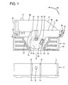
- FIG. 1 is a plan view of a male housing and a female housing of a lever-type connector according to one embodiment of the invention with the female housing having a lever mounted at a standby position therein shown partly in section,
- FIG. 2 is a section of the male housing and the female housing having the lever mounted at the standby position therein,
- FIG. 3 is a front view of the female housing,
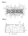
- FIG. 4 is a rear view of the female housing,
- FIG. 5 is a front view of the female housing,
- FIG. 6 is a section along A-A of FIG. 4,
- FIG. 7 is a plan view of the lever,
- FIG. 8 is a section along B-B of FIG. 7,
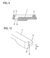
- FIG. 9 is a section along C-C of FIG. 7,
- FIG. 10 is a partial enlarged perspective view of a locking
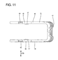
claw 17, - FIG. 11 is a bottom view of the lever,
- FIG. 12(a) is a partial enlarged section showing an engaged state of the locking claw and an engaging portion and FIG. 12(b) is a partial enlarged section showing an operation of disengaging the locking claw from the engaging portion,
- FIG. 13 is a plan view partly in section showing a connected state of the two housings.
- One preferred embodiment of the present invention is described with reference to FIGS. 1 to 13. A connector of the movable member type, preferably a lever-type connector according to this embodiment is provided with a female housing 10 (corresponding to a preferred first housing), a
lever 11 as a preferred movable member movably (preferably rotatably or pivotably) mounted in or on thefemale housing 10, and a male housing 12 (corresponding to a preferred second housing) connectable with thefemale housing 10 through the operation of the movable member (preferably though rotation or pivotal movement of the lever 11) or the connection of thehousings operable member 11. In the following description, connecting directions CD of the twohousings - The
male housing 12 is made e.g. of a synthetic resin and provided with areceptacle 13 having an open front side. One or more maleterminal fittings 14 substantially in the form of narrow and long bars are arranged at the back wall of thereceptacle 13 while penetrating through this back wall substantially in forward and backward directions, and end portions of the maleterminal fittings 14 at one side project into thereceptacle 13. One or more substantially cylindrical cam pins 15 are formed to project laterally (upward and/or downward) at a widthwise intermediate position (preferably near the widthwise centers) of one or more lateral surfaces (preferably the top and/or bottom surfaces) of thereceptacle 13. One or morerestriction lifting portions 16 extending substantially in forward and backward directions FBD (or substantially along the connecting direction CD) and projecting in vertical direction (or in a direction at an angle different from 0° or 180°, preferably substantially normal to the connecting direction CD) are formed at the (preferably substantially opposite) lateral (left and/or right) side(s) of eachcam pin 15, and function to resiliently deform a lockingclaw 17 to be described later in an unlocking direction UD by coming into engagement therewith during a connecting operation of the twohousings claw 17 from an engagingportion 18 to be described later. One or more slanted orrounded surfaces 19 are formed at or near the front ends of therestriction lifting portions 16 to facilitate an upward or deflecting movement of the lockingclaw 17. - The
female housing 10 is made e.g. of a synthetic resin and preferably provided with anouter tube portion 20 and aninner tube portion 21 formed inside theouter tube portion 20. A space between theouter tube portion 20 and theinner tube portion 21 serves as a receptaclefitting space 22 into which thereceptacle 13 of themale housing 12 is at least partly fittable during the connecting operation of the twohousings lever accommodating spaces 23 are formed at inner lateral (upper and/or lower) side(s) of theouter tube portion 20 to at least partly penetrate theouter tube portion 20 substantially in forward and backward directions FBD, and thelever 11 is or may be at least partly accommodated in thesespaces 23. A substantially cylindrical supportingshaft 24 extends downward or inwardly from the inner outer (upper) surface of the lateral (upper)lever accommodating space 23, whereas a substantially cylindrical supportingshaft 24 extends upward or inwardly from the outer (inner) lateral (bottom) surface of the other lateral (lower)lever accommodating space 23. A (preferably substantially rectangular) cut-outportion 25 is formed to extend substantially backward from the front edge at a widthwise intermediate position (preferably near or at the widthwise center) of each of the inner (bottom) wall of the lateral (upper)lever accommodating space 23 and the inner (upper) wall of the other lateral (lower)lever accommodating space 23. The cam pins 15 of themale housing 12 and therestriction lifting portions 16 at the opposite sides of the cam pins 15 are at least partly insertable into these cut-outportions 25. Each cut-outportion 25 has a width slightly larger than a spacing between therestriction lifting portions 16 at its front side and is narrowed with steps to have the substantially same width as the spacing between therestriction lifting portions 16 at an intermediate position (preferably at a position slightly behind a middle part) thereof with respect to depth direction, and the back end thereof is closed. One or more stepped portions of the cut-outportion 25 are rounded or slanted and serve as the engagingportions 18. The respectiveengaging portions 18 are formed at the free end edge or front portion of the lateral (upper and/or bottom) wall of thelever accommodating space 23 and are resiliently deformable along the thickness direction TD (or in a direction at an angle different from 0° or 180°, preferably substantially normal to a relative direction of thelever 11 with respect to the housing 10) of the upper and/or bottom wall of thelever accommodating space 23. - One or
more cavities 29 for at least partly accommodating femaleterminal fittings 28 to be connected with ends ofrespective wires 27 are formed to penetrate theinner tube portion 21 substantially in forward and backward directions FBD. Each female terminal fitting 28 is comprised of a wire connection portion (preferably comprising a barrel portion 30) to be connected (preferably crimped or bent or folded into connection) with thewire 27, and a (preferably substantially rectangular)tube portion 31 formed before or adjacent to thebarrel portion 30. The male terminal fitting 14 is to be at least partly inserted into this (rectangular)tube portion 31 to establish an electrical connection between the male terminal fitting 14 and the female terminal fitting 28. A (preferably substantially cantilever-shaped) lockingportion 32 preferably extending substantially forward is formed at an inner wall of eachcavity 29 and engageable with the (rectangular)tube portion 31 to retain the female terminal fitting 28. Anaccommodating recess 33 communicating with the rear ends or rear end portions of thecavities 29 is formed at the rear end of theinner tube portion 21, and preferably a resilient plug (such as a one-piece rubber plug 34) is or may be at least partly accommodated in thisaccommodating recess 33. This one-piece rubber plug 34 preferably is in the form of a thick plate and formed with one or more plug-side insertion holes 35 penetrating the plug 34 substantially in forward and backward directions FBD to permit the passage of thewires 27. Sealing is provided between thewires 27 and the one-piece rubber plug 34 by the close contact of the inner walls of the plug-side insertion holes 35 and the insulation coatings of thewires 27. Sealing is also provided between the one-piece rubber plug 34 and thefemale housing 10 by the close contact of the outer circumferential wall of the one-piece rubber plug 34 and the inner circumferential wall of theaccommodating recess 33. A resilient-plug holder or rubber-plug holder 36 is to be preferably arranged behind the one-piece rubber plug 34 and held in theinner tube portion 21 by the engagement of one ormore locking projections 37 projecting outward from the outer surface of the rubber-plug holder 36 with one or more respective receiving portions 38 formed at positions of theinner tube portion 21 near the rear end. The rubber-plug holder 36 is formed with one or more holder-side insertion holes 39 penetrating the rubber-plug holder 36 substantially in forward and backward directions FBD to permit the passage of thewires 27, and the insertedwires 27 are drawn out preferably substantially backward. - A
wire cover 40 preferably is to be mounted at or on the rear side of thefemale housing 10. Thewire cover 40 is made e.g. of a synthetic resin and substantially has a box shape with an opening extending over the front surface and a lateral end surface (left end surface in FIG. 1). A closed substantially opposite side is slanted to form an escapingsurface 41. At anopen end surface 44 of thewire cover 40, one or more, preferably a pair of resilient lockinglegs 42 project from the front edges of both side plates preferably in such a manner as to substantially face each other. At or near the rear end of thefemale housing 10, one or more, preferably a pair of lateral (upper and/or lower)protrusions 43 are formed at each of the lateral (left and/or right) ends of the lateral (top and/or bottom) surfaces which are longer sides. - The wire cover 40 preferably is to be so attached as to at least partly cover the rear surface of the
female housing 10, and mounted in such a posture that theopen end surface 44 faces laterally, e.g. leftward (see FIG. 1) by the engagement of the pair of resilient lockinglegs 42 with the pair ofprotrusions 43 arranged at either left or right side. Thus, thewires 27 drawn out from the rear surface of thefemale housing 10 are or may be bent sideways at an angle different from 0° or 180°, preferably substantially at 90° after being bundled, and let out to left through theopen end surface 44. - The lever 11 (as the preferred movable member) is made e.g. of a synthetic resin and is substantially gate-shaped by coupling (preferably substantially rectangular)
arm portions 46 extending laterally (rightward in FIG. 1) from the outer peripheries of a pair of substantiallyround side plates 45 by an operable portion 47 (see FIG. 11). Thislever 11 is formed by a mold (not shown) openable and closable along the thickness direction of theside plates 45. Forward, backward, leftward and rightward directions in the description of thelever 11 are based on a state where thelever 11 is so assembled into thefemale housing 10 as to be rotatable in operable direction OD (in counterclockwise direction) from the standby position SP to the connection position CP and is located at the standby position SP in thefemale housing 10. One or more shaft holes 48 are formed to penetrate (preferably substantially in the centers of) theside plates 45, and the aforementioned supportingshafts 24 are at least partly inserted or insertable thereinto. The inner surfaces of theside plates 45 of thelever 11 facing each other are recessed in the thickness direction LTD of theside plates 45 to formcam grooves 49, which are engageable with the aforementioned cam pins 15. Eachcam groove 49 has a specified (predetermined or predeterminable) curved shape about theshaft hole 48, and the entrance thereof is located at the peripheral edge of theside plate 45. - The
lever 11 is at least partly inserted or accommodated into thelever accommodating spaces 23 of thefemale housing 10 from an inserting side, preferably from behind, such that bothside plates 45 hold thefemale housing 10 therebetween, and is movably (rotatably or pivotably) mounted between the standby position SP and the connection position CP substantially about the supportingshafts 24 by at least partly fitting the supportingshafts 24 into the shaft holes 48. It should be noted that the standby position SP is a position of thelever 11 where the entrances of thecam grooves 49 and the cam pins 15 substantially face each other and the entrance of the cam pins 15 into thecam grooves 49 is permitted (see FIG. 1), and the connection position CP is a position of thelever 11 where the twohousings - When the
lever 11 is moved in the operating direction OD (e.g. rotated or pivoted in counterclockwise direction) from the standby position SP shown in FIG. 1 to the connection position CP shown in FIG. 13, theoperable portion 47 preferably comes into contact with the rear surface of thewire cover 40, thereby preventing any further counterclockwise rotation. On the other hand, theoperable portion 47 is provided with at least one resilientlydeformable locking piece 50, and a lockingprojection 51 is formed on the rear surface of thewire cover 40 at a position substantially corresponding to thelocking piece 50. Thus, when thelever 11 is moved (rotated or pivoted) to the connection position CP, the lockingpiece 50 is resiliently engaged with the lockingprojection 51 to lock thelever 11, thereby preventing a movement towards the standby position SP (i.e. a clockwise rotation in FIG. 13) or preventing a movement in a direction substantially opposite to the operating direction OD. - As shown in FIG. 7, each
side plate 45 is provided with the lockingclaw 17 engageable with the engagingportion 18 of the aforementionedfemale housing 10 preferably at a position at a side of or adjacent to theshaft hole 48 substantially opposite to the end of thecam groove 49. The lockingclaw 17 preferably is formed inside a substantiallyU-shaped slit 52 made in theside plate 45, and has a substantially narrow and long shape substantially in forward and backward directions. The lockingclaw 17 is resiliently deformable along the thickness direction LTD of the side plate 45 (or in the unlocking direction UD) with the base end thereof as a fixed end. The inner surface of the lockingclaw 17 is formed to project from the inner surface of theside plate 45, and normally projects inward from the inner surface of the side plate 45 (see FIG. 11). - A
contact surface 53 that can come substantially into contact with the aforementioned engagingportion 18 is formed at a lateral-inner (right-lower) side of the leading end of the lockingclaw 17 in FIG. 7. Thiscontact surface 53 is formed with such a slanted or roundedsurface 54 as to exert a force acting in a direction (downward direction in FIG. 12(a)) substantially opposite to an unlocking direction UD (upward direction in FIG. 12(a)) of the lockingclaw 17 to the lockingclaw 17 when thecontact surface 53 comes substantially into contact with the engagingportion 18. Specifically, the slantedsurface 54 is inclined or rounded obliquely downward to right in FIG. 12(a). Thus, a resilient deformation of the lockingclaw 17 in the unlocking direction UD can be prevented when the lockingclaw 17 and the engagingportion 18 come substantially into contact, wherefore the lockingclaw 17 and the engagingportion 18 can be securely engaged. - At a lateral-outer (left-upper) side of the leading end of the locking
claw 17 in FIG. 7, a turn-up preventingportion 55 for pressing the engagingportion 18 in a direction opposite to the unlocking direction UD of the lockingclaw 17 to prevent the engagingportion 18 from being turned up and undergoing such a resilient deformation as to move onto the slantedsurface 54 when thecontact surface 53 and the engagingportion 18 come substantially into contact is formed preferably to project substantially away from the side where thecam groove 49 opens (backward in FIG. 7). Thus, a sufficient holding force can be ensured between the lockingclaw 17 and the engaging portion 18 (see FIG. 12(a)). - As described above, since the slanted
surface 54 and the turn-up preventingportion 55 are displaced from each other in the width direction WD of the lockingclaw 17, thelever 11 can be formed even using a mold openable and closable along the thickness direction of the lockingclaw 17. - A movement or rotation path of the
lever 11 from the standby position SP to the connection position CP is set in the substantially same direction as the one in which the contact surfaces 53 comes into contact with the engagingportions 18. Thus, if thelever 11 is operated or moved (rotated or pivoted) before the connecting operation of the twohousings lever 11 located at the standby position SP in thefemale housing 10, a movement (rotation or pivotal movement) of thelever 11 in the operating direction OD toward the connection position CP is prevented (see FIG. 12(a)) by the contact of the lockingclaws 17 and the engagingportions 18 of thefemale housing 10 as shown in FIG. 1. - If the female and
male housings lever 11 held at the standby position SP in thefemale housing 10, the restrictinglifting portions 16 formed on themale housing 12 come substantially into contact with the lockingclaws 17 from the inner side, thereby resiliently deforming the lockingclaws 17 in the unlocking direction UD or outward of the female housing 10 (see FIG. 12(b)). After being freed from the locked state, the lockingclaws 17 slide substantially on the inner surfaces of the inner (bottom) wall of the lateral (upper)lever accommodating space 23 and the inner (upper) wall of the other lateral (lower)lever accommodating space 23 as thelever 11 is operated or rotated, whereby thelever 11 is displaced in the operating direction OD towards or to the connection position CP. - Next, functions and effects of this embodiment are described. First, the
wire cover 40 preferably is mounted on the rear surface of thefemale housing 10. If it is desired to let thewires 27 out laterally (leftward when viewed from front), thewire cover 40 is mounted in such a posture that theopen end surface 44 faces laterally (leftward as shown in FIG. 2). Subsequently, thelever 11 is mounted to thehousing 10, preferably at least partly accommodated in thelever accommodating spaces 23 in such a posture that theoperable portion 47 is located at the side of the escapingsurface 41 of thewire cover 40, i.e. theoperable portion 47 faces laterally (rightward), and supported on the supportingshafts 24 at the standby position SP where theoperable portion 47 preferably rests on or is close to the lateral (right) side of the rear surface of thefemale housing 10. At this standby position SP, the entrances of thecam grooves 49 face substantially forward (or towards the male housing 12) in intermediate positions (preferably substantially in the centers) of the cut-outportions 25. - If an attempt is made to move (rotate or pivot) the
lever 11 in the operating direction OD toward the connection position CP with thelever 11 located at the standby position SP, the contact surface(s) 53 formed at or near the leading end(s) of the locking claw(s) 17 come substantially into contact with the lateral (right) engagingportions 18. Then, the engagingportions 18 exert forces on the slanted surfaces 54 formed on the contact surfaces 53 in directions substantially opposite to the unlocking directions UD of the lockingclaws 17, wherefore the lockingclaws 17 and the engagingportions 18 can be securely engaged to ensure a sufficient holding force for holding thelever 11 at the standby position SP. Even if the engagingportions 18 formed at the resiliently deformable free edges are so deformed as to be turned up and move onto the slanted surfaces 54 (see FIG. 12(a)), the turn-up preventingportions 55 press the engagingportions 18 from the opposite sides of the lockingclaws 17, thereby preventing the engagingportions 18 from being turned in unlocking direction UD or substantially up. Therefore, the holding forces of the lockingclaws 17 and the engagingportions 18 can be further increased. In this way, thelever 11 is so held as not to inadvertently rotate toward the connection position CP. - The
female housing 10 having thelever 11 mounted therein in this way is lightly fitted to the matingmale housing 12 along the connecting direction CD, as shown by an arrow in FIG. 1. As thefemale housing 10 is more fitted, the cam pins 15 of themale housing 12 at least partly enter thecam grooves 49 and therestriction lifting portions 16 at least partly enter the cut-outportions 25, whereby the rightrestriction lifting portions 16 resiliently deform the lockingclaws 17 in unlocking direction UD or outward of thefemale housing 10 while slipping under the lockingclaws 17 utilizing the slanted surfaces 19, thereby disengaging the lockingclaws 17 from the engagingportions 18 as shown in FIG. 12(b). In this way, the restriction on the movement or rotation of thelever 11 toward the connection position CP is lifted or canceled. Since the operating direction OD (rotating or pivoting direction) of thelever 11 at the standby position SP preferably is set to be a direction (upward direction in FIG. 1) substantially opposite to the connecting direction CD (downward direction in FIG. 1) of the twohousings lever 11 is operated or pressed toward the connection position CP in a direction substantially opposite to the one necessary for connecting the twohousings housings claws 17 and the engagingportions 18 are not engaged and the restriction can be easily lifted or canceled. - Subsequently, when the
lever 11 is operated in operating direction OD (rotated in counterclockwise direction of FIG. 13) by holding or manipulating theoperable portion 47, thefemale housing 10 is pulled toward the male housing 12 (or the connection of thehousings cam grooves 49 toward the back ends of thecam grooves 49. When thelever 11 is operated (rotated or pivoted) to the connection position CP as shown in FIG. 13, the cam pins 15 preferably substantially reach the back ends of thecam grooves 49 and the twohousings piece 50 provided in theoperable portion 47 preferably is resiliently engaged with the lockingprojection 37 of thewire cover 40, thereby preventing a returning movement of thelever 11 to lock the twohousings - In the case of separating the two
housings piece 50 is forcibly resiliently deformed to be disengaged from the lockingprojection 37 and, thereafter, thelever 11 is operated (rotated or pivoted) in the direction opposite to the above operating direction OD toward the standby position SP. Then, the cam pins 15 are moved in an opposite direction in thecam grooves 49 and a resulting cam action is displayed to separate the twohousings - As described above, according to this embodiment, the contact surfaces 53 are formed with such
slanted surfaces 54 as to exert forces acting in directions substantially opposite to the unlocking directions UD of the lockingclaws 17 to the lockingclaws 17 when the engagingportions 18 come substantially into contact with the contact surfaces 53. Thus, resilient deformations of the lockingclaws 17 in the unlocking directions UD can be prevented when the engagingportions 18 come substantially into contact with the contact surfaces 53, wherefore the lockingclaws 17 and the engagingportions 18 can be securely engaged with each other. - Further, since the turn-up preventing
portions 55 preferably formed on the lockingclaws 17 can prevent the engagingportions 18 brought into contact with the contact surfaces 53 from undergoing such deformations as to be turned in unlocking direction UD or up and move onto the lockingclaws 17, sufficient holding forces can be ensured between the lockingclaws 17 and the engagingportions 18. - Furthermore, since the locking
claws 17 preferably are formed inside theslits 52 made in theside plates 45, they are arranged inside the movement or rotation path of thelever 11. This can prevent the enlargement of the rotation path of thelever 11 and also the enlargement of thefemale housing 10. - However, with the above construction, if the turn-up preventing
portions 55 and theslanted surfaces 54 are arranged to at least partly overlap in the thickness direction LTD of the lockingclaws 17 when thelever 11 is formed using the mold openable and closable along the thickness direction of the lockingclaws 17, no spaces used to remove mold parts for forming the turn-upportions 55 and theslanted surfaces 54 can be ensured since the lockingclaws 17 are at least partly surrounded by theside plates 45. Therefore, there is a possibility of being unable to form the turn-up preventingportions 55 and the slanted surfaces 54. - In view of this, the turn-up preventing
portions 55 and theslanted surfaces 54 are displaced in width direction WD in this embodiment. Thus, the turn-up preventingportions 55 and theslanted surfaces 54 can be formed even in the case of using the mold openable and closable along the thickness direction of the lockingclaws 17. - Further, the locking
claws 17 and the engagingportions 18 can be disengaged by therestriction lifting portions 16 by lightly fitting the female andmale housings housings claws 17 and the engagingportions 18 is necessary. - Accordingly, to provide a connector of the movable member type, preferably a lever-type connector, having an increased holding force for holding a movable member (preferably a lever) at a standby position in or on a housing, a movable member such as a
lever 11 is so mounted in or on afemale housing 10 as to be movable or operatable (preferably rotatable or pivotable) between a standby position SP and a connection position CP. Thelever 11 is formed with one or more resilientlydeformable locking claws 17, which come into contact with one or moreengaging portions 18 preferably formed at free end edges of outer surfaces of thefemale housing 10 if an attempt is made to move the operable member (e.g. rotate the lever 11) at the standby position SP. Acontact surface 53 that can be brought substantially into contact with the corresponding engagingportion 18 and a turn-up preventingportion 55 for pressing the engagingportion 18 to prevent the engagingportion 18 from being turned up or deformed in an unlocking direction UD are formed at or near the leading end of each lockingclaw 17. Since this can prevent the engagingportions 18 from being turned up or deformed in the unlocking direction UD during an engaging operation of the lockingclaws 17 and the engagingportions 18, a holding force for holding thelever 11 at the standby position SP can be increased. - The present invention is not limited to the above described and illustrated embodiment. For example, the following embodiments are also embraced by the technical scope of the present invention as defined by the claims. Beside the following embodiments, various changes can be made without departing from the scope and spirit of the present invention as defined by the claims.
- (1) Although the
lever 11 is substantially gate-shaped and rotatably mounted in thefemale housing 10 in the foregoing embodiment, the present invention is not limited thereto. Thelever 11 may be a substantially plate-shaped rotary lever or a slide lever. Particularly, the operable member may be a slider movable along an operation path being substantially linear or a bent or elliptic path. - (2) Although the contact surfaces 53 are formed with the
slanted surfaces 54 for exerting forces acting in the directions opposite to the unlocking direction UD to the lockingclaws 17 in the foregoing embodiment, the present invention is not limited thereto and the contact surfaces 53 may be formed to be at an angle different from 0° or 180°, preferably substantially perpendicular to a direction in which the contact surfaces 53 come into contact with the engagingportions 18. In such a case, the contact surfaces 53 can be formed also by the mold openable and closable along the thickness direction of the lockingclaws 17. Therefore, the contact surfaces 53 and the turn-up preventingportions 55 can be arranged to overlap in the thickness direction of the lockingclaws 17. - (3) Although the
wires 27 are drawn out to left in FIG. 1 in the foregoing embodiment, the present invention is not limited thereto and thewires 27 may be drawn out to right. In such a case, thewire cover 40 is mounted such that theopen end surface 44 faces to right and thelever 11 is supported on the supportingshafts 24 at the standby position where theoperable portion 47 faces to left. At this time, theleft engaging portions 18 are used to lock thelever 11 at the standby position. The succeeding process is not described because it only differs form the foregoing embodiment in that the rotating direction and the like of thelever 11 are reversed. Moreover, the cover may be also completely dispensed with. - (4) Although the locking
claws 17 are formed inside theslits 52 made in theside plates 45 of thelever 11 in the foregoing embodiment, the present invention is not limited thereto and the lockingclaws 17 may project outward from the lateral edges of theside plates 45. Alternatively, only areas of the lockingclaws 17 different from those where the slanted surfaces 54 and the turn-up preventingportions 55 are formed may be surrounded by theslits 52. Since the mold can be removed in a direction intersecting with the thickness direction of the lockingclaws 17 in such a case, theslanted surfaces 54 and the turn-up preventingportions 55 can be arranged to overlap in the thickness direction of the lockingclaws 17. - (5) Although the
lever 11 is at least partly accommodated in thelever accommodating spaces 23 formed in thefemale housing 10 in the foregoing embodiment, the present invention is not limited thereto and thelever 11 may be at least partly exposed on the outer walls of thefemale housing 10. - (6) Although the first housing is the
female housing 10 and the second housing is themale housing 12 in the foregoing embodiment, the present invention is not limited thereto and the first housing may be themale housing 12 and the second housing may be thefemale housing 10. -
- 10 ...
- female housing (housing/first housing)
- 11 ...
- lever (movable member)
- 12 ...
- male housing (mating housing/second housing)
- 15 ...
- cam pin (mating cam member)
- 16 ...
- restriction lifting portion
- 17 ...
- locking claw
- 18 ...
- engaging portion
- 45 ...
- side plate
- 49 ...
- cam groove (cam member)
- 52 ...
- slit
- 53 ...
- contact surface
- 54 ...
- slanted surface
- 55 ...
- turn-up preventing portion (deformation preventing portion)
Claims (10)
- A connector, comprising:a housing (10) being connectable with a mating housing (12) of a mating connector,a movable member (11) having at least one cam member (49) formed in at least one side plate (45) thereof and at least partly mounted in or on the first housing (10) in such a manner as to be displaceable between a standby position (SP) and a connection position (CP), andthe cam member (49) being engageable with a mating cam member (15) of the mating housing (12) for displaying a cam action to connect or assist the connection of the housing (10) with the mating housing (12) when the operable member (11) is displaced towards or to the connection position (CP) after the housing (10) is lightly fitted to the mating housing (12) with the movable member (11) located at the standby position (SP),wherein:the side plate (45) of the movable member (11) is formed with at least one locking claw (17) resiliently deformable along the thickness direction (LTD) of the side plate (45), the locking claw (17) being formed with a contact surface (53),an engaging portion (18) engageable with the contact surface is formed at the housing (10),the locking claw (17) and the engaging portion (18) are engaged with each other with the movable member (11) located at the standby position (SP), thereby preventing the movable member (11) from being displaced towards or to the connection position (CP),the locking claw (17) is resiliently deformed in an unlocking direction (UD) to be disengaged from the engaging portion (18) by the engagement with the second housing (12) when the two housings (10, 12) are lightly fitted to each other with the movable member (11) located at the standby position (SP),a displacement path of the movable member (11) from the standby position (SP) to the connection position (CP) is set in the substantially same direction as a direction in which the contact surface (53) comes substantially into contact with the engaging portion (18), andthe locking claw (17) is formed with a deformation preventing portion (55) for pressing the engaging portion (18) in a direction opposite to an unlocking direction (UD) of the locking claw (17) to prevent the engaging portion (18) from being resiliently deformed when the contact surface (53) and the engaging portion (18) are brought substantially into contact with each other upon displacing the movable member (11) before a connecting operation of the housing (10) with the mating housing (12).
- A connector according to claim 1, wherein the contact surface (53) is formed with a slanted or rounded surface (54) for exerting such a force acting in a direction opposite to the unlocking direction (UD) of the locking claw (17) to the locking claw (17) when the contact surface (53) comes into contact with the engaging portion (18).
- A connector according to one or more of the preceding claims, wherein:the movable member (11) is made of a synthetic resin,the locking claw (17) is formed inside a slit (52) made in the side plate (45) and formed by a mold openable and closable along the thickness direction of the locking claw (17).
- A connector according to one or more of the preceding claims in combination with claim 2, wherein the slanted surface (54) is displaced from the deformation preventing portion (55) in the width direction (WD) of the locking claw (17).
- A connector according to one or more of the preceding claims, wherein the operating direction (OD) of the movable member (11) at the standby position (SP) is set to be a direction substantially opposite to the connecting direction (CD) of the two housings (10, 12).
- A connector assembly comprising a connector according to one or more of the preceding claims and a mating connector connectable therewith, wherein the housing (10) of the connector being connectable with the mating housing (12) of the mating connector and the connection of the housings (10, 12) is performed or assisted by the operation of the movable member (11) provided in or on the connector.
- A connector assembly according to claim 6, wherein the mating housing (12) includes at least one restriction lifting portion (16) for resiliently deforming the locking claw (17) in the unlocking direction (UD) to disengage the locking claw (17) from the engaging portion (18) by coming substantially into contact with the locking claw (17) when the two housings (10, 12) are lightly fitted to each other with the movable member (11) located at the standby position (SP).
- A method of assembling a connector assembly, comprising the following steps:providing a connector comprising a first housing (10) and a movable member (11) having at least one cam member (49) formed in at least one side plate (45) thereof and at least partly mounted in or on the first housing (10) in such a manner as to be displaceable between a standby position (SP) and a connection position (CP),providing a second housing (12) formed with at least one mating cam member (15) engageable with the cam member (49) of the movable member (11), anddisplacing the operable member (11) towards or to the connection position (CP) after the first and second housings (10, 12) are lightly fitted to each other with the movable member (11) located at the standby position (SP) thereby connecting the two connector housings (10, 12) or assisting their connection by means of the cam member (49) and the mating cam member (15) displaying a cam action,
wherein:the side plate (45) of the movable member (11) is formed with at least one locking claw (17) resiliently deformable along the thickness direction (LTD) of the side plate (45), the locking claw (17) being formed with a contact surface (53),an engaging portion (18) engageable with the contact surface is formed at the first housing (10),the locking claw (17) and the engaging portion (18) are engaged with each other with the movable member (11) located at the standby position (SP), thereby preventing the movable member (11) from being displaced towards or to the connection position (CP),the locking claw (17) is resiliently deformed in an unlocking direction (UD) to be disengaged from the engaging portion (18) by the engagement with the second housing (12) when the two housings (10, 12) are lightly fitted to each other with the movable member (11) located at the standby position (SP),a displacement path of the movable member (11) from the standby position (SP) to the connection position (CP) is set in the substantially same direction as a direction in which the contact surface (53) comes substantially into contact with the engaging portion (18), andthe engaging portion (18) is pressed by means of a deformation preventing portion (55) of the locking claw (17) in a direction opposite to an unlocking direction (UD) of the locking claw (17) to prevent the engaging portion (18) from being resiliently deformed when the contact surface (53) and the engaging portion (18) are brought substantially into contact with each other upon displacing the movable member (11) before a connecting operation of the first and second housings (10, 12). - A method according to claim 8, further comprising a step of exerting by means of a slanted or rounded surface (54) of the contact surface (53) such a force acting in a direction opposite to the unlocking direction (UD) of the locking claw (17) to the locking claw (17) when the contact surface (53) comes into contact with the engaging portion (18).
- A method according to claim 8 or 9, wherein the movable member (11) at the standby position (SP) in a direction (OD) substantially opposite to the connecting direction (CD) of the two housings (10, 12).
Applications Claiming Priority (1)
| Application Number | Priority Date | Filing Date | Title |
|---|---|---|---|
| JP2005196420A JP4497038B2 (en) | 2005-07-05 | 2005-07-05 | Lever type connector |
Publications (2)
| Publication Number | Publication Date |
|---|---|
| EP1742302A1 true EP1742302A1 (en) | 2007-01-10 |
| EP1742302B1 EP1742302B1 (en) | 2008-10-15 |
Family
ID=37076258
Family Applications (1)
| Application Number | Title | Priority Date | Filing Date |
|---|---|---|---|
| EP06013400A Ceased EP1742302B1 (en) | 2005-07-05 | 2006-06-28 | A connector, connector assembly and assembling method therefor |
Country Status (5)
| Country | Link |
|---|---|
| US (1) | US7189086B2 (en) |
| EP (1) | EP1742302B1 (en) |
| JP (1) | JP4497038B2 (en) |
| CN (1) | CN100502159C (en) |
| DE (1) | DE602006003137D1 (en) |
Families Citing this family (16)
| Publication number | Priority date | Publication date | Assignee | Title |
|---|---|---|---|---|
| US7396240B2 (en) * | 2006-04-05 | 2008-07-08 | J.S.T. Corporation | Electrical connector with a locking mechanism |
| JP4248001B2 (en) * | 2006-10-19 | 2009-04-02 | 古河電気工業株式会社 | Lever connector |
| US7374460B1 (en) | 2007-04-17 | 2008-05-20 | Traxxas Lp | Electrical connector assembly |
| JP4960853B2 (en) * | 2007-12-20 | 2012-06-27 | 矢崎総業株式会社 | Lever type connector |
| JP5343902B2 (en) * | 2010-03-17 | 2013-11-13 | 住友電装株式会社 | connector |
| JP5678827B2 (en) * | 2011-07-14 | 2015-03-04 | 住友電装株式会社 | Lever type connector |
| JP5748692B2 (en) * | 2012-03-08 | 2015-07-15 | ヒロセ電機株式会社 | Electrical connector |
| JP2014149954A (en) | 2013-01-31 | 2014-08-21 | Sumitomo Wiring Syst Ltd | Lever-type connector |
| JP5929829B2 (en) * | 2013-05-21 | 2016-06-08 | 住友電装株式会社 | Lever type connector |
| JP6117023B2 (en) | 2013-07-02 | 2017-04-19 | モレックス エルエルシー | connector |
| JP2016207414A (en) * | 2015-04-21 | 2016-12-08 | 住友電装株式会社 | connector |
| JP6492030B2 (en) * | 2016-05-30 | 2019-03-27 | 矢崎総業株式会社 | connector |
| EP3392979B1 (en) * | 2017-04-19 | 2020-01-29 | Aptiv Technologies Limited | Electrical connector with lever and methods of assembling thereof |
| JP6931561B2 (en) * | 2017-07-04 | 2021-09-08 | 日本航空電子工業株式会社 | connector |
| JP2020202053A (en) * | 2019-06-07 | 2020-12-17 | 矢崎総業株式会社 | Lever type connector |
| JP2022115418A (en) * | 2021-01-28 | 2022-08-09 | 住友電装株式会社 | lever type connector |
Citations (6)
| Publication number | Priority date | Publication date | Assignee | Title |
|---|---|---|---|---|
| JPH08167448A (en) * | 1994-12-14 | 1996-06-25 | Sumitomo Wiring Syst Ltd | connector |
| EP1100160A1 (en) * | 1999-11-10 | 2001-05-16 | Molex Incorporated | Electrical connector assembly with improved camming system |
| US20020016100A1 (en) * | 2000-07-25 | 2002-02-07 | Yazaki Coroporation | Connector supporting structure |
| US20030017026A1 (en) * | 2001-07-23 | 2003-01-23 | Sumitomo Wiring Systems, Ltd. | Lever-type connector |
| US20040121640A1 (en) * | 2002-12-12 | 2004-06-24 | Sumitomo Wiring Systems, Ltd. | Connector and a connector assembly |
| WO2006023673A1 (en) * | 2004-08-20 | 2006-03-02 | Molex Incorporated | Lever type electrical connector |
Family Cites Families (13)
| Publication number | Priority date | Publication date | Assignee | Title |
|---|---|---|---|---|
| JP3449947B2 (en) * | 1999-05-26 | 2003-09-22 | 矢崎総業株式会社 | Electric junction box lever structure |
| JP2001250634A (en) * | 2000-03-02 | 2001-09-14 | Auto Network Gijutsu Kenkyusho:Kk | Connector coupling structure and its holder unit |
| JP3726638B2 (en) * | 2000-05-16 | 2005-12-14 | 住友電装株式会社 | Lever type connector |
| JP3726641B2 (en) * | 2000-05-23 | 2005-12-14 | 住友電装株式会社 | Lever type connector |
| JP3829615B2 (en) * | 2000-10-31 | 2006-10-04 | 住友電装株式会社 | connector |
| JP2002164115A (en) * | 2000-11-28 | 2002-06-07 | Sumitomo Wiring Syst Ltd | Lever connector |
| DE10232392B4 (en) * | 2001-07-19 | 2012-07-19 | Sumitomo Wiring Systems, Ltd. | Interconnects |
| JP2003223958A (en) * | 2002-01-29 | 2003-08-08 | Sumitomo Wiring Syst Ltd | Lever type connector |
| JP3987736B2 (en) * | 2002-02-26 | 2007-10-10 | 住友電装株式会社 | Lever type connector |
| JP2003249309A (en) * | 2002-02-26 | 2003-09-05 | Sumitomo Wiring Syst Ltd | Split connector |
| JP2004319125A (en) | 2003-04-11 | 2004-11-11 | Sumitomo Wiring Syst Ltd | Lever type connector |
| JP4001113B2 (en) * | 2004-01-14 | 2007-10-31 | 住友電装株式会社 | Lever type connector |
| DE102005050625B4 (en) * | 2004-10-22 | 2011-07-28 | Sumitomo Wiring Systems, Ltd., Mie | Connector and connector assembly |
-
2005
- 2005-07-05 JP JP2005196420A patent/JP4497038B2/en not_active Expired - Fee Related
-
2006
- 2006-06-28 EP EP06013400A patent/EP1742302B1/en not_active Ceased
- 2006-06-28 DE DE602006003137T patent/DE602006003137D1/en not_active Expired - Lifetime
- 2006-07-05 US US11/481,229 patent/US7189086B2/en not_active Expired - Lifetime
- 2006-07-05 CN CNB2006101031394A patent/CN100502159C/en not_active Expired - Fee Related
Patent Citations (6)
| Publication number | Priority date | Publication date | Assignee | Title |
|---|---|---|---|---|
| JPH08167448A (en) * | 1994-12-14 | 1996-06-25 | Sumitomo Wiring Syst Ltd | connector |
| EP1100160A1 (en) * | 1999-11-10 | 2001-05-16 | Molex Incorporated | Electrical connector assembly with improved camming system |
| US20020016100A1 (en) * | 2000-07-25 | 2002-02-07 | Yazaki Coroporation | Connector supporting structure |
| US20030017026A1 (en) * | 2001-07-23 | 2003-01-23 | Sumitomo Wiring Systems, Ltd. | Lever-type connector |
| US20040121640A1 (en) * | 2002-12-12 | 2004-06-24 | Sumitomo Wiring Systems, Ltd. | Connector and a connector assembly |
| WO2006023673A1 (en) * | 2004-08-20 | 2006-03-02 | Molex Incorporated | Lever type electrical connector |
Also Published As
| Publication number | Publication date |
|---|---|
| JP2007018764A (en) | 2007-01-25 |
| JP4497038B2 (en) | 2010-07-07 |
| CN100502159C (en) | 2009-06-17 |
| DE602006003137D1 (en) | 2008-11-27 |
| US7189086B2 (en) | 2007-03-13 |
| EP1742302B1 (en) | 2008-10-15 |
| US20070010113A1 (en) | 2007-01-11 |
| CN1893198A (en) | 2007-01-10 |
Similar Documents
| Publication | Publication Date | Title |
|---|---|---|
| EP2224549B1 (en) | Lever-type connector, connector assembly and connecting method | |
| EP1672747B1 (en) | A connector | |
| EP1830436B1 (en) | A connector, connector assembly and assembling method | |
| US8251761B2 (en) | Connector | |
| EP1715551B1 (en) | A connector and a method of assembling it | |
| EP1742302B1 (en) | A connector, connector assembly and assembling method therefor | |
| US7931483B2 (en) | Lever-type connector | |
| US6773279B2 (en) | Lever-type connector, a lever-type connector assembly and a method of assembling a lever-type connector with a mating connector | |
| US20060030186A1 (en) | Connector having a movable member and connector assembly | |
| US6733313B2 (en) | Connector having an operable member and a connector assembly | |
| EP1734619A1 (en) | A connector and connector assembly of the movable member type | |
| EP2456020B1 (en) | Lever-type connector | |
| US8215970B2 (en) | Connector | |
| EP1594195A1 (en) | A connector and a method of assembling/disassembling it | |
| US20110130026A1 (en) | Lever-type connector | |
| US6623286B2 (en) | Lever-type connector | |
| EP1775801B1 (en) | A connector having a movable member | |
| US7445474B2 (en) | Lever-type connector and lever-type connector assembly | |
| EP2317609B1 (en) | Connector, series of connectors and method of assembling it | |
| JP2000195617A (en) | connector |
Legal Events
| Date | Code | Title | Description |
|---|---|---|---|
| PUAI | Public reference made under article 153(3) epc to a published international application that has entered the european phase |
Free format text: ORIGINAL CODE: 0009012 |
|
| 17P | Request for examination filed |
Effective date: 20060705 |
|
| AK | Designated contracting states |
Kind code of ref document: A1 Designated state(s): AT BE BG CH CY CZ DE DK EE ES FI FR GB GR HU IE IS IT LI LT LU LV MC NL PL PT RO SE SI SK TR |
|
| AX | Request for extension of the european patent |
Extension state: AL BA HR MK YU |
|
| AKX | Designation fees paid |
Designated state(s): DE FR |
|
| GRAP | Despatch of communication of intention to grant a patent |
Free format text: ORIGINAL CODE: EPIDOSNIGR1 |
|
| GRAS | Grant fee paid |
Free format text: ORIGINAL CODE: EPIDOSNIGR3 |
|
| GRAA | (expected) grant |
Free format text: ORIGINAL CODE: 0009210 |
|
| AK | Designated contracting states |
Kind code of ref document: B1 Designated state(s): DE FR |
|
| REF | Corresponds to: |
Ref document number: 602006003137 Country of ref document: DE Date of ref document: 20081127 Kind code of ref document: P |
|
| REG | Reference to a national code |
Ref country code: DE Ref legal event code: R096 Ref document number: 602006003137 Country of ref document: DE Effective date: 20081127 |
|
| PLBE | No opposition filed within time limit |
Free format text: ORIGINAL CODE: 0009261 |
|
| STAA | Information on the status of an ep patent application or granted ep patent |
Free format text: STATUS: NO OPPOSITION FILED WITHIN TIME LIMIT |
|
| 26N | No opposition filed |
Effective date: 20090716 |
|
| REG | Reference to a national code |
Ref country code: DE Ref legal event code: R097 Ref document number: 602006003137 Country of ref document: DE Effective date: 20090716 |
|
| REG | Reference to a national code |
Ref country code: FR Ref legal event code: PLFP Year of fee payment: 11 |
|
| REG | Reference to a national code |
Ref country code: FR Ref legal event code: PLFP Year of fee payment: 12 |
|
| REG | Reference to a national code |
Ref country code: DE Ref legal event code: R084 Ref document number: 602006003137 Country of ref document: DE |
|
| REG | Reference to a national code |
Ref country code: FR Ref legal event code: PLFP Year of fee payment: 13 |
|
| PGFP | Annual fee paid to national office [announced via postgrant information from national office to epo] |
Ref country code: FR Payment date: 20220510 Year of fee payment: 17 |
|
| P01 | Opt-out of the competence of the unified patent court (upc) registered |
Effective date: 20230517 |
|
| PGFP | Annual fee paid to national office [announced via postgrant information from national office to epo] |
Ref country code: DE Payment date: 20230502 Year of fee payment: 18 |
|
| PG25 | Lapsed in a contracting state [announced via postgrant information from national office to epo] |
Ref country code: FR Free format text: LAPSE BECAUSE OF NON-PAYMENT OF DUE FEES Effective date: 20230630 |
|
| REG | Reference to a national code |
Ref country code: DE Ref legal event code: R119 Ref document number: 602006003137 Country of ref document: DE |
|
| PG25 | Lapsed in a contracting state [announced via postgrant information from national office to epo] |
Ref country code: DE Free format text: LAPSE BECAUSE OF NON-PAYMENT OF DUE FEES Effective date: 20250101 |