EP1742291B1 - System for deploying an antenna of an integrated circuit card - Google Patents
System for deploying an antenna of an integrated circuit card Download PDFInfo
- Publication number
- EP1742291B1 EP1742291B1 EP06019335A EP06019335A EP1742291B1 EP 1742291 B1 EP1742291 B1 EP 1742291B1 EP 06019335 A EP06019335 A EP 06019335A EP 06019335 A EP06019335 A EP 06019335A EP 1742291 B1 EP1742291 B1 EP 1742291B1
- Authority
- EP
- European Patent Office
- Prior art keywords
- antenna
- housing
- card
- integrated circuit
- circuit card
- Prior art date
- Legal status (The legal status is an assumption and is not a legal conclusion. Google has not performed a legal analysis and makes no representation as to the accuracy of the status listed.)
- Expired - Lifetime
Links
Images


Classifications
-
- H—ELECTRICITY
- H01—ELECTRIC ELEMENTS
- H01Q—ANTENNAS, i.e. RADIO AERIALS
- H01Q1/00—Details of, or arrangements associated with, antennas
- H01Q1/12—Supports; Mounting means
- H01Q1/22—Supports; Mounting means by structural association with other equipment or articles
- H01Q1/2258—Supports; Mounting means by structural association with other equipment or articles used with computer equipment
- H01Q1/2275—Supports; Mounting means by structural association with other equipment or articles used with computer equipment associated to expansion card or bus, e.g. in PCMCIA, PC cards, Wireless USB
-
- H—ELECTRICITY
- H01—ELECTRIC ELEMENTS
- H01Q—ANTENNAS, i.e. RADIO AERIALS
- H01Q1/00—Details of, or arrangements associated with, antennas
- H01Q1/12—Supports; Mounting means
- H01Q1/22—Supports; Mounting means by structural association with other equipment or articles
-
- H—ELECTRICITY
- H01—ELECTRIC ELEMENTS
- H01Q—ANTENNAS, i.e. RADIO AERIALS
- H01Q1/00—Details of, or arrangements associated with, antennas
- H01Q1/36—Structural form of radiating elements, e.g. cone, spiral, umbrella; Particular materials used therewith
-
- H—ELECTRICITY
- H01—ELECTRIC ELEMENTS
- H01Q—ANTENNAS, i.e. RADIO AERIALS
- H01Q9/00—Electrically-short antennas having dimensions not more than twice the operating wavelength and consisting of conductive active radiating elements
- H01Q9/04—Resonant antennas
- H01Q9/0407—Substantially flat resonant element parallel to ground plane, e.g. patch antenna
- H01Q9/0414—Substantially flat resonant element parallel to ground plane, e.g. patch antenna in a stacked or folded configuration
Definitions
- the present invention relates to integrated circuit cards, for example, integrated circuit cards meeting the Personal Computer Memory Card International Association (PCMCIA) specifications; and more particularly, a system for deploying an antenna of an integrated circuit card.
- PCMCIA Personal Computer Memory Card International Association
- PCMCIA Integrated circuit card standards
- PCMCIA for example established specifications for use of credit card sized electronic cards to interface with computers.
- a standard PCMCIA card is substantially housed within a computer, for example, a laptop computer, when inserted.
- the radiation characteristics of an antenna or antennas forming a part of a wireless network interface card meeting PCMCIA standards are quite poor.
- an antenna which is a [0002A]
- an antenna which is a push-in antenna
- an antenna structure is contained in an antenna structure.
- a sliding connector comprising a comb of eight metal fingers is positioned on the rear of a radio transceiver printed circuit board ("'PCB").
- 'PCB radio transceiver printed circuit board
- a PC card is configured for insertion into a computer PC card slot.
- a sliding assembly is housed within the PC card.
- An antenna element is fitted inside the sliding assembly.
- an antenna portion is slid in or out of an opening slot.
- the antenna or antennas of the wireless network interface card can be positioned outside of the computer to improve radiation characteristics. Because the non-standard PCMCIA card extends out beyond the PCMCIA compartment of the computer, the card is not protected and subject to possible damage. Further, problems arise in transporting the computer. To fit within a carrying case or shipping container, the PCMCIA card often has to be removed, which is seen as a disadvantage by computer users and manufacturers.
- the present invention provides an integrated circuit card that includes a system for deploying an antenna.
- An antenna housing is provided movably connected to the card housing.
- the antenna housing protects the antenna, and by moving the antenna housing relative to the card housing, a distal end of the antenna is extended or retracted relative to the card housing.
- the integrated circuit card meets standards when the antenna housing is in the retracted state, but provides for beneficial radiation characteristics in the extended state. As such, removing and replacing the integrated circuit card to transport a computer is not required, and when not in use, the integrated circuit card is protected from damage.
- FIGs. 1A-1B and 2A-2B illustrate cross-sectional views of two different integrated circuit card embodiments according to the present invention
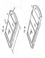
- Fig. 3A and 3B illustrate a perspective view an integrated circuit card according to the present invention.
- Figs. 4 and 5 illustrate prior art devices having pop-out components.
- Figs. 3A and 3B illustrate an integrated circuit card 10 according to the present invention.
- the integrated circuit card 10 includes a card housing 12, which houses and protects electronic components, and an antenna housing 14, which houses and protects at least one antenna.
- Fig. 3A shows the integrated circuit card 10 with the antenna housing 14 in the retracted state
- Fig. 3B shows the integrated circuit card 10 with the antenna housing 14 in the extended state.
- the length L of the integrated circuit card 10 meets a desired standard such as PCMCIA, discussed above.
- Figs. 1A-1B and 2A-2B illustrates two different embodiments of the integrated circuit card 10.
- Each of the illustrated embodiments is a cross-section view of the integrated circuit card 10 shown in Figs. 3A-3B .
- the same reference numeral as used in Figs. 3A-5B will be used to designate the antenna housing in each embodiment to promote ease of understanding.
- Fig. 1A illustrates a double antenna embodiment of the present invention in the retracted state.
- the antenna housing 14 defines two channels 8. Each channel 8 is L-shaped and one of the channels 8 overlaps the other.
- a first antenna 16 has a first proximal end 20 fixed to the card housing 12, and a second antenna 18 has a second proximal end 22 fixed to the card housing 12.
- the first and second proximal ends 20 and 22 are electrically connected in any well-known manner to the electronic components within the card housing 12.
- Distal ends 24 and 26 of the first and second antennas 16 and 18, respectively, are disposed and freely slide within a respective one of the channels 8 in the antenna housing 14.
- the antenna housing 14 is moveable (e.g., slides) relative to the card housing 12. As the antenna housing 14 is slid out from the card housing 12, the distal ends 24 and 26 of the first and second antennas 16 and 18 slide within their respective channels 8. In the fully extended state of Fig. 1B , flanges 28 of the antenna housing 14 abut the interior wall of the card housing 12, and prevent the antenna housing 14 from becoming separated from the card housing 12. As will be appreciated from Fig. 5B, as the antennas housing 14 is extended from the card housing 12, the first and second antennas 16 and 18 are deployed. When deployed, the first and second antennas 16 and 18 extend away from the card housing 12, thus improving their radiation characteristics. To return to the retracted state, an operator slides the antenna housing back towards the card housing 12.
- Figs. 2A and 2B illustrate the retracted and extended states of a single antenna embodiment of the present invention that is similar to the embodiment of the Figs. 1A and 1B . Accordingly, a redundant description of the this embodiment will not be made, and this embodiment is fully understood from the description of the embodiment of Figs. 1A and 1B .
- Figs. 4 and 5 illustrate two different types of circuit cards having pop-out components.
- Fig. 4 illustrates a fingerprint recognition card produced by Duel Systems.
- the pop-out part of this card includes the scan electronics to take a sample of a fingertip.
- Fig. 5 illustrates a connector for wireless Bluetooth products produced by Nissan.
- the pop-out part includes the radio module for the device. Neither of these devices includes an antenna in the pop-out part
Landscapes
- Engineering & Computer Science (AREA)
- Computer Networks & Wireless Communication (AREA)
- Computer Hardware Design (AREA)
- General Engineering & Computer Science (AREA)
- Support Of Aerials (AREA)
- Details Of Aerials (AREA)
- Devices For Checking Fares Or Tickets At Control Points (AREA)
Abstract
Description
- The present invention relates to integrated circuit cards, for example, integrated circuit cards meeting the Personal Computer Memory Card International Association (PCMCIA) specifications; and more particularly, a system for deploying an antenna of an integrated circuit card.
- Integrated circuit card standards such as PCMCIA were established to facilitate uniformity among vendors. PCMCIA for example established specifications for use of credit card sized electronic cards to interface with computers. However, many providers of wireless network interface cards for computers have resorted to using a non-standard PCMCIA card. A standard PCMCIA card is substantially housed within a computer, for example, a laptop computer, when inserted. As a result the radiation characteristics of an antenna or antennas forming a part of a wireless network interface card meeting PCMCIA standards are quite poor.
- For example, in European Patent Application
EP 1,075,038A2 , an antenna, which is a [0002A] For example, in European Patent ApplicationEP 1,075,038A2 , an antenna, which is a push-in antenna, is contained in an antenna structure. In Patent Cooperation Treaty Patent ApplicationPCT/GB00/04339 U.S. Patent No. 6,259,409 to Fulton et al , a PC card is configured for insertion into a computer PC card slot. A sliding assembly is housed within the PC card. An antenna element is fitted inside the sliding assembly. In Patent Cooperation Treaty Patent ApplicationPCT/US00/09516 , an antenna portion is slid in or out of an opening slot. - By resorting to a non-standard PCMCIA card, the antenna or antennas of the wireless network interface card can be positioned outside of the computer to improve radiation characteristics. Because the non-standard PCMCIA card extends out beyond the PCMCIA compartment of the computer, the card is not protected and subject to possible damage. Further, problems arise in transporting the computer. To fit within a carrying case or shipping container, the PCMCIA card often has to be removed, which is seen as a disadvantage by computer users and manufacturers.
- The present invention provides an integrated circuit card that includes a system for deploying an antenna. An antenna housing is provided movably connected to the card housing. The antenna housing protects the antenna, and by moving the antenna housing relative to the card housing, a distal end of the antenna is extended or retracted relative to the card housing.
- Through this design, the integrated circuit card meets standards when the antenna housing is in the retracted state, but provides for beneficial radiation characteristics in the extended state. As such, removing and replacing the integrated circuit card to transport a computer is not required, and when not in use, the integrated circuit card is protected from damage.
- The present invention will become more fully understood from the detailed description given herein below and the accompanying drawings which are given by way of illustration only, wherein like reference numerals designate corresponding parts in the various drawings, and wherein:
-
Figs. 1A-1B and 2A-2B , illustrate cross-sectional views of two different integrated circuit card embodiments according to the present invention; -
Fig. 3A and 3B illustrate a perspective view an integrated circuit card according to the present invention; and -
Figs. 4 and 5 illustrate prior art devices having pop-out components. -
Figs. 3A and 3B illustrate anintegrated circuit card 10 according to the present invention. As shown, the integratedcircuit card 10 includes acard housing 12, which houses and protects electronic components, and anantenna housing 14, which houses and protects at least one antenna.Fig. 3A shows theintegrated circuit card 10 with theantenna housing 14 in the retracted state, andFig. 3B shows theintegrated circuit card 10 with theantenna housing 14 in the extended state. When theantenna housing 14 is in the retracted state as shown inFig. 3A , the length L of theintegrated circuit card 10 meets a desired standard such as PCMCIA, discussed above. -
Figs. 1A-1B and 2A-2B illustrates two different embodiments of theintegrated circuit card 10. Each of the illustrated embodiments is a cross-section view of theintegrated circuit card 10 shown inFigs. 3A-3B . Even though each embodiment has a differently constructed antenna housing, the same reference numeral as used inFigs. 3A-5B will be used to designate the antenna housing in each embodiment to promote ease of understanding. - Referring to
Fig. 1A, Fig. 1A illustrates a double antenna embodiment of the present invention in the retracted state. As shown, theantenna housing 14 defines twochannels 8. Eachchannel 8 is L-shaped and one of thechannels 8 overlaps the other. Afirst antenna 16 has a firstproximal end 20 fixed to thecard housing 12, and asecond antenna 18 has a secondproximal end 22 fixed to thecard housing 12. The first and secondproximal ends card housing 12. Distal ends 24 and 26 of the first andsecond antennas channels 8 in theantenna housing 14. - The
antenna housing 14 is moveable (e.g., slides) relative to thecard housing 12. As theantenna housing 14 is slid out from thecard housing 12, the distal ends 24 and 26 of the first andsecond antennas respective channels 8. In the fully extended state ofFig. 1B ,flanges 28 of the antenna housing 14 abut the interior wall of thecard housing 12, and prevent theantenna housing 14 from becoming separated from thecard housing 12. As will be appreciated from Fig. 5B, as theantennas housing 14 is extended from thecard housing 12, the first andsecond antennas second antennas card housing 12, thus improving their radiation characteristics. To return to the retracted state, an operator slides the antenna housing back towards thecard housing 12. -
Figs. 2A and 2B illustrate the retracted and extended states of a single antenna embodiment of the present invention that is similar to the embodiment of theFigs. 1A and 1B . Accordingly, a redundant description of the this embodiment will not be made, and this embodiment is fully understood from the description of the embodiment ofFigs. 1A and 1B . -
Figs. 4 and 5 illustrate two different types of circuit cards having pop-out components.Fig. 4 illustrates a fingerprint recognition card produced by Duel Systems. As shown, the pop-out part of this card includes the scan electronics to take a sample of a fingertip.Fig. 5 illustrates a connector for wireless Bluetooth products produced by Honda. In this device, the pop-out part includes the radio module for the device. Neither of these devices includes an antenna in the pop-out part - The invention being thus described, it will be obvious that the same may be varied in many ways. Such variations are not to be regarded as a departure from the scope of the invention, and all such modifications are intended to be included within the scope of the following claims.
Claims (4)
- A system for deploying an antenna (16, 18, 36, 28, 66, 68) of an integrated circuit card (10), including:- a card housing (12) protecting electronic components;- an antenna housing (14) movably connected with the card housing (12); characterized by at least one antenna (16, 18, 36, 38, 66, 68) having a proximal end (20, 22, 40, 42, 74, 76) and a distal end (24, 26, 46, 48, 70, 72), the distal end (24, 26, 46, 48, 70, 72) protected by the antenna housing (14), and the distal end (24, 26, 46, 48, 70, 72) of the antenna (16, 18, 36, 38, 66, 68) moving within the antenna housing (14) in association with movement of the antenna housing (14).
- The system of claim 1, wherein the proximal end (20, 22, 40, 42, 74, 76) is electrically connected to the electronic components.
- The system of claim 1, wherein the proximal end (20, 22, 40, 42, 74, 76) is fixed relative to the card housing (12).
- The system of claim 1, wherein the antenna housing (14) includes a channel (8, 60, 62) formed therein; and the distal end (24, 26, 46, 48, 70, 72) slides within the channel (8, 60, 62).
Applications Claiming Priority (2)
| Application Number | Priority Date | Filing Date | Title |
|---|---|---|---|
| US10/042,510 US6720927B2 (en) | 2002-01-09 | 2002-01-09 | System for deploying an antenna of an integrated circuit card |
| EP02806443A EP1468469B1 (en) | 2002-01-09 | 2002-11-20 | A system for deploying an antenna of an integrated circuit card |
Related Parent Applications (2)
| Application Number | Title | Priority Date | Filing Date |
|---|---|---|---|
| EP02806443A Division EP1468469B1 (en) | 2002-01-09 | 2002-11-20 | A system for deploying an antenna of an integrated circuit card |
| EP02806443.4 Division | 2002-11-20 |
Related Child Applications (1)
| Application Number | Title | Priority Date | Filing Date |
|---|---|---|---|
| EP11195815.3 Division-Into | 2011-12-27 |
Publications (2)
| Publication Number | Publication Date |
|---|---|
| EP1742291A1 EP1742291A1 (en) | 2007-01-10 |
| EP1742291B1 true EP1742291B1 (en) | 2012-11-07 |
Family
ID=21922311
Family Applications (2)
| Application Number | Title | Priority Date | Filing Date |
|---|---|---|---|
| EP06019335A Expired - Lifetime EP1742291B1 (en) | 2002-01-09 | 2002-11-20 | System for deploying an antenna of an integrated circuit card |
| EP02806443A Expired - Lifetime EP1468469B1 (en) | 2002-01-09 | 2002-11-20 | A system for deploying an antenna of an integrated circuit card |
Family Applications After (1)
| Application Number | Title | Priority Date | Filing Date |
|---|---|---|---|
| EP02806443A Expired - Lifetime EP1468469B1 (en) | 2002-01-09 | 2002-11-20 | A system for deploying an antenna of an integrated circuit card |
Country Status (7)
| Country | Link |
|---|---|
| US (1) | US6720927B2 (en) |
| EP (2) | EP1742291B1 (en) |
| JP (1) | JP4240527B2 (en) |
| KR (2) | KR20040071281A (en) |
| AT (1) | ATE340418T1 (en) |
| DE (1) | DE60214895T2 (en) |
| WO (1) | WO2003061064A1 (en) |
Families Citing this family (10)
| Publication number | Priority date | Publication date | Assignee | Title |
|---|---|---|---|---|
| CN1689240A (en) * | 2002-10-03 | 2005-10-26 | 松下电器产业株式会社 | terminal device |
| WO2004088791A1 (en) * | 2003-03-28 | 2004-10-14 | Fujitsu Limited | Radio apparatus |
| EP1677523A3 (en) * | 2004-12-28 | 2011-03-30 | LG Electronics, Inc. | Digital broadcasting transmitter-receiver for portable computer |
| JP4517998B2 (en) * | 2005-10-07 | 2010-08-04 | パナソニック電工株式会社 | Memory card socket |
| US20080166902A1 (en) * | 2007-01-03 | 2008-07-10 | Newton Peripherals, Llc | Dongle device |
| US8214003B2 (en) * | 2009-03-13 | 2012-07-03 | Pong Research Corporation | RF radiation redirection away from portable communication device user |
| EP2249432A1 (en) * | 2009-05-07 | 2010-11-10 | Gemalto SA | Device designed to equip a terminal with all or some radiofrequency functions |
| US8936199B2 (en) | 2012-04-13 | 2015-01-20 | Blackberry Limited | UICC apparatus and related methods |
| USD703208S1 (en) * | 2012-04-13 | 2014-04-22 | Blackberry Limited | UICC apparatus |
| USD701864S1 (en) * | 2012-04-23 | 2014-04-01 | Blackberry Limited | UICC apparatus |
Family Cites Families (16)
| Publication number | Priority date | Publication date | Assignee | Title |
|---|---|---|---|---|
| US5943018A (en) * | 1993-08-19 | 1999-08-24 | Toshiba America Information Systems, Inc. | Portable GPS receiver unit |
| US5918163A (en) * | 1995-03-31 | 1999-06-29 | Compaq Computer Corporation | Electronic card assembly having a retractable antenna |
| US5657028A (en) * | 1995-03-31 | 1997-08-12 | Nokia Moblie Phones Ltd. | Small double C-patch antenna contained in a standard PC card |
| US5684672A (en) * | 1996-02-20 | 1997-11-04 | International Business Machines Corporation | Laptop computer with an integrated multi-mode antenna |
| US6522299B2 (en) * | 1999-04-08 | 2003-02-18 | Cypress Semiconductor Corp. | PC card retractable antenna |
| US6259409B1 (en) | 1999-07-22 | 2001-07-10 | 3Com Corporation | Retractable sliding antenna assembly for wireless communication |
| FI108205B (en) * | 1999-08-06 | 2001-11-30 | Nokia Mobile Phones Ltd | Card-like wireless communication means and antenna construction |
| JP2001102949A (en) * | 1999-09-28 | 2001-04-13 | Matsushita Electric Ind Co Ltd | Wireless communication terminal |
| FI19992267A7 (en) * | 1999-10-20 | 2001-06-11 | Nokia Mobile Phones Ltd | Expansion card for wireless communication and its antenna structure |
| JP2003514482A (en) | 1999-11-15 | 2003-04-15 | サイオン コネクト リミテッド | Removable wireless device |
| JP4221878B2 (en) * | 2000-01-25 | 2009-02-12 | ソニー株式会社 | Antenna device |
| DE10038287A1 (en) * | 2000-08-05 | 2002-02-21 | Itt Mfg Enterprises Inc | Plug-in card for electronic devices |
| US6509876B1 (en) * | 2000-09-08 | 2003-01-21 | 3Com Corporation | Antenna for wireless communication system |
| US6359591B1 (en) * | 2000-10-19 | 2002-03-19 | Sierra Wireless, Inc. | Locking antenna for personal computer card |
| US6456245B1 (en) * | 2000-12-13 | 2002-09-24 | Magis Networks, Inc. | Card-based diversity antenna structure for wireless communications |
| KR20010035232A (en) * | 2001-01-19 | 2001-05-07 | 양준영 | Slide system and Single end system of Loop antenna |
-
2002
- 2002-01-09 US US10/042,510 patent/US6720927B2/en not_active Expired - Lifetime
- 2002-11-20 EP EP06019335A patent/EP1742291B1/en not_active Expired - Lifetime
- 2002-11-20 KR KR10-2004-7010458A patent/KR20040071281A/en not_active Ceased
- 2002-11-20 JP JP2003561041A patent/JP4240527B2/en not_active Expired - Fee Related
- 2002-11-20 KR KR1020097026062A patent/KR100951849B1/en not_active Expired - Fee Related
- 2002-11-20 EP EP02806443A patent/EP1468469B1/en not_active Expired - Lifetime
- 2002-11-20 WO PCT/US2002/037185 patent/WO2003061064A1/en not_active Ceased
- 2002-11-20 DE DE60214895T patent/DE60214895T2/en not_active Expired - Lifetime
- 2002-11-20 AT AT02806443T patent/ATE340418T1/en not_active IP Right Cessation
Also Published As
| Publication number | Publication date |
|---|---|
| DE60214895D1 (en) | 2006-11-02 |
| KR100951849B1 (en) | 2010-04-12 |
| DE60214895T2 (en) | 2007-04-05 |
| US6720927B2 (en) | 2004-04-13 |
| KR20100008000A (en) | 2010-01-22 |
| WO2003061064A1 (en) | 2003-07-24 |
| EP1468469A4 (en) | 2005-02-02 |
| EP1468469B1 (en) | 2006-09-20 |
| KR20040071281A (en) | 2004-08-11 |
| JP4240527B2 (en) | 2009-03-18 |
| US20030128166A1 (en) | 2003-07-10 |
| ATE340418T1 (en) | 2006-10-15 |
| EP1742291A1 (en) | 2007-01-10 |
| EP1468469A1 (en) | 2004-10-20 |
| JP2005515678A (en) | 2005-05-26 |
Similar Documents
| Publication | Publication Date | Title |
|---|---|---|
| US6343945B1 (en) | Cardholder cover and ejector | |
| EP1180814B1 (en) | A plug-in card with retractable antenna for electronic portable devices | |
| US7427206B2 (en) | Card connector | |
| AU701349B2 (en) | Smart card computer adaptor | |
| US6132223A (en) | PC adaptor card for IC stick | |
| KR100694604B1 (en) | Adapter for Card Connection | |
| US7540782B2 (en) | Card connector and method for producing housing assembly | |
| US7979089B2 (en) | Wireless data communication card with compact antenna | |
| US6422469B1 (en) | Chip card reader | |
| US20020163472A1 (en) | Radio communication card | |
| US8062067B2 (en) | USB connector | |
| FI109447B (en) | Card Adapter | |
| US20020114447A1 (en) | Card connector | |
| US6594506B1 (en) | Antenna structure in an expansion card for an electronic device | |
| US6752320B1 (en) | Wireless communication device card and an antenna structure | |
| EP1468469B1 (en) | A system for deploying an antenna of an integrated circuit card | |
| US6494745B1 (en) | PC card that receives and guides chip card | |
| EP2214252A1 (en) | Radio device | |
| EP0926940A1 (en) | Method and apparatus for providing RF shielding in a PCMCIA standard enclosure | |
| US20040185695A1 (en) | Card slot unit for portable digital equipment | |
| CN101361223A (en) | Combination antenna and sim card support structure | |
| JP2002343468A (en) | IC card connector | |
| WO2004015818A1 (en) | Low-profile stacked media card connector |
Legal Events
| Date | Code | Title | Description |
|---|---|---|---|
| PUAI | Public reference made under article 153(3) epc to a published international application that has entered the european phase |
Free format text: ORIGINAL CODE: 0009012 |
|
| AC | Divisional application: reference to earlier application |
Ref document number: 1468469 Country of ref document: EP Kind code of ref document: P |
|
| AK | Designated contracting states |
Kind code of ref document: A1 Designated state(s): AT BE BG CH CY CZ DE DK EE ES FI FR GB GR IE IT LI LU MC NL PT SE SK TR |
|
| 17P | Request for examination filed |
Effective date: 20070704 |
|
| 17Q | First examination report despatched |
Effective date: 20070806 |
|
| AKX | Designation fees paid |
Designated state(s): DE GB |
|
| GRAP | Despatch of communication of intention to grant a patent |
Free format text: ORIGINAL CODE: EPIDOSNIGR1 |
|
| GRAS | Grant fee paid |
Free format text: ORIGINAL CODE: EPIDOSNIGR3 |
|
| GRAA | (expected) grant |
Free format text: ORIGINAL CODE: 0009210 |
|
| REG | Reference to a national code |
Ref country code: DE Ref legal event code: R081 Ref document number: 60244016 Country of ref document: DE Owner name: AVAGO TECHNOLOGIES GENERAL IP (SINGAPORE) PTE., SG Free format text: FORMER OWNER: AGERE SYSTEMS, INC., ALLENTOWN, PA., US |
|
| AC | Divisional application: reference to earlier application |
Ref document number: 1468469 Country of ref document: EP Kind code of ref document: P |
|
| AK | Designated contracting states |
Kind code of ref document: B1 Designated state(s): DE GB |
|
| REG | Reference to a national code |
Ref country code: GB Ref legal event code: FG4D |
|
| REG | Reference to a national code |
Ref country code: DE Ref legal event code: R096 Ref document number: 60244016 Country of ref document: DE Effective date: 20130103 |
|
| PLBE | No opposition filed within time limit |
Free format text: ORIGINAL CODE: 0009261 |
|
| STAA | Information on the status of an ep patent application or granted ep patent |
Free format text: STATUS: NO OPPOSITION FILED WITHIN TIME LIMIT |
|
| 26N | No opposition filed |
Effective date: 20130808 |
|
| REG | Reference to a national code |
Ref country code: DE Ref legal event code: R097 Ref document number: 60244016 Country of ref document: DE Effective date: 20130808 |
|
| PGFP | Annual fee paid to national office [announced via postgrant information from national office to epo] |
Ref country code: GB Payment date: 20151027 Year of fee payment: 14 |
|
| REG | Reference to a national code |
Ref country code: DE Ref legal event code: R081 Ref document number: 60244016 Country of ref document: DE Owner name: AVAGO TECHNOLOGIES GENERAL IP (SINGAPORE) PTE., SG Free format text: FORMER OWNER: AGERE SYSTEMS, INC., ALLENTOWN, PA., US Ref country code: DE Ref legal event code: R081 Ref document number: 60244016 Country of ref document: DE Owner name: AVAGO TECHNOLOGIES INTERNATIONAL SALES PTE. LT, SG Free format text: FORMER OWNER: AGERE SYSTEMS, INC., ALLENTOWN, PA., US |
|
| REG | Reference to a national code |
Ref country code: DE Ref legal event code: R081 Ref document number: 60244016 Country of ref document: DE Owner name: AVAGO TECHNOLOGIES GENERAL IP (SINGAPORE) PTE., SG Free format text: FORMER OWNER: AGERE SYSTEMS LLC (N.D.GES.D. STAATES DELAWARE), ALLENTOWN, PA., US Ref country code: DE Ref legal event code: R081 Ref document number: 60244016 Country of ref document: DE Owner name: AVAGO TECHNOLOGIES INTERNATIONAL SALES PTE. LT, SG Free format text: FORMER OWNER: AGERE SYSTEMS LLC (N.D.GES.D. STAATES DELAWARE), ALLENTOWN, PA., US |
|
| GBPC | Gb: european patent ceased through non-payment of renewal fee |
Effective date: 20161120 |
|
| PG25 | Lapsed in a contracting state [announced via postgrant information from national office to epo] |
Ref country code: GB Free format text: LAPSE BECAUSE OF NON-PAYMENT OF DUE FEES Effective date: 20161120 |
|
| REG | Reference to a national code |
Ref country code: DE Ref legal event code: R081 Ref document number: 60244016 Country of ref document: DE Owner name: AVAGO TECHNOLOGIES INTERNATIONAL SALES PTE. LT, SG Free format text: FORMER OWNER: AVAGO TECHNOLOGIES GENERAL IP (SINGAPORE) PTE. LTD., SINGAPORE, SG Ref country code: DE Ref legal event code: R082 Ref document number: 60244016 Country of ref document: DE Representative=s name: DILG, HAEUSLER, SCHINDELMANN PATENTANWALTSGESE, DE Ref country code: DE Ref legal event code: R082 Ref document number: 60244016 Country of ref document: DE Representative=s name: DILG HAEUSLER SCHINDELMANN PATENTANWALTSGESELL, DE |
|
| PGFP | Annual fee paid to national office [announced via postgrant information from national office to epo] |
Ref country code: DE Payment date: 20191127 Year of fee payment: 18 |
|
| REG | Reference to a national code |
Ref country code: DE Ref legal event code: R119 Ref document number: 60244016 Country of ref document: DE |
|
| PG25 | Lapsed in a contracting state [announced via postgrant information from national office to epo] |
Ref country code: DE Free format text: LAPSE BECAUSE OF NON-PAYMENT OF DUE FEES Effective date: 20210601 |