EP1742249A1 - Power field effect transistor and manufacturing method thereof - Google Patents
Power field effect transistor and manufacturing method thereof Download PDFInfo
- Publication number
- EP1742249A1 EP1742249A1 EP05425495A EP05425495A EP1742249A1 EP 1742249 A1 EP1742249 A1 EP 1742249A1 EP 05425495 A EP05425495 A EP 05425495A EP 05425495 A EP05425495 A EP 05425495A EP 1742249 A1 EP1742249 A1 EP 1742249A1
- Authority
- EP
- European Patent Office
- Prior art keywords
- type
- semiconductor
- conductivity
- semiconductor layer
- dopant
- Prior art date
- Legal status (The legal status is an assumption and is not a legal conclusion. Google has not performed a legal analysis and makes no representation as to the accuracy of the status listed.)
- Ceased
Links
Images



Classifications
-
- H—ELECTRICITY
- H10—SEMICONDUCTOR DEVICES; ELECTRIC SOLID-STATE DEVICES NOT OTHERWISE PROVIDED FOR
- H10D—INORGANIC ELECTRIC SEMICONDUCTOR DEVICES
- H10D30/00—Field-effect transistors [FET]
- H10D30/60—Insulated-gate field-effect transistors [IGFET]
- H10D30/64—Double-diffused metal-oxide semiconductor [DMOS] FETs
- H10D30/66—Vertical DMOS [VDMOS] FETs
-
- H—ELECTRICITY
- H10—SEMICONDUCTOR DEVICES; ELECTRIC SOLID-STATE DEVICES NOT OTHERWISE PROVIDED FOR
- H10D—INORGANIC ELECTRIC SEMICONDUCTOR DEVICES
- H10D12/00—Bipolar devices controlled by the field effect, e.g. insulated-gate bipolar transistors [IGBT]
- H10D12/01—Manufacture or treatment
- H10D12/031—Manufacture or treatment of IGBTs
-
- H—ELECTRICITY
- H10—SEMICONDUCTOR DEVICES; ELECTRIC SOLID-STATE DEVICES NOT OTHERWISE PROVIDED FOR
- H10D—INORGANIC ELECTRIC SEMICONDUCTOR DEVICES
- H10D62/00—Semiconductor bodies, or regions thereof, of devices having potential barriers
- H10D62/01—Manufacture or treatment
- H10D62/051—Forming charge compensation regions, e.g. superjunctions
- H10D62/058—Forming charge compensation regions, e.g. superjunctions by using trenches, e.g. implanting into sidewalls of trenches or refilling trenches
-
- H—ELECTRICITY
- H10—SEMICONDUCTOR DEVICES; ELECTRIC SOLID-STATE DEVICES NOT OTHERWISE PROVIDED FOR
- H10D—INORGANIC ELECTRIC SEMICONDUCTOR DEVICES
- H10D62/00—Semiconductor bodies, or regions thereof, of devices having potential barriers
- H10D62/10—Shapes, relative sizes or dispositions of the regions of the semiconductor bodies; Shapes of the semiconductor bodies
- H10D62/102—Constructional design considerations for preventing surface leakage or controlling electric field concentration
- H10D62/103—Constructional design considerations for preventing surface leakage or controlling electric field concentration for increasing or controlling the breakdown voltage of reverse-biased devices
- H10D62/105—Constructional design considerations for preventing surface leakage or controlling electric field concentration for increasing or controlling the breakdown voltage of reverse-biased devices by having particular doping profiles, shapes or arrangements of PN junctions; by having supplementary regions, e.g. junction termination extension [JTE]
- H10D62/109—Reduced surface field [RESURF] PN junction structures
- H10D62/111—Multiple RESURF structures, e.g. double RESURF or 3D-RESURF structures
-
- H—ELECTRICITY
- H10—SEMICONDUCTOR DEVICES; ELECTRIC SOLID-STATE DEVICES NOT OTHERWISE PROVIDED FOR
- H10D—INORGANIC ELECTRIC SEMICONDUCTOR DEVICES
- H10D62/00—Semiconductor bodies, or regions thereof, of devices having potential barriers
- H10D62/80—Semiconductor bodies, or regions thereof, of devices having potential barriers characterised by the materials
- H10D62/83—Semiconductor bodies, or regions thereof, of devices having potential barriers characterised by the materials being Group IV materials, e.g. B-doped Si or undoped Ge
- H10D62/832—Semiconductor bodies, or regions thereof, of devices having potential barriers characterised by the materials being Group IV materials, e.g. B-doped Si or undoped Ge being Group IV materials comprising two or more elements, e.g. SiGe
- H10D62/8325—Silicon carbide
-
- H—ELECTRICITY
- H10—SEMICONDUCTOR DEVICES; ELECTRIC SOLID-STATE DEVICES NOT OTHERWISE PROVIDED FOR
- H10D—INORGANIC ELECTRIC SEMICONDUCTOR DEVICES
- H10D30/00—Field-effect transistors [FET]
- H10D30/01—Manufacture or treatment
- H10D30/021—Manufacture or treatment of FETs having insulated gates [IGFET]
- H10D30/028—Manufacture or treatment of FETs having insulated gates [IGFET] of double-diffused metal oxide semiconductor [DMOS] FETs
- H10D30/0291—Manufacture or treatment of FETs having insulated gates [IGFET] of double-diffused metal oxide semiconductor [DMOS] FETs of vertical DMOS [VDMOS] FETs
-
- H—ELECTRICITY
- H10—SEMICONDUCTOR DEVICES; ELECTRIC SOLID-STATE DEVICES NOT OTHERWISE PROVIDED FOR
- H10D—INORGANIC ELECTRIC SEMICONDUCTOR DEVICES
- H10D64/00—Electrodes of devices having potential barriers
- H10D64/20—Electrodes characterised by their shapes, relative sizes or dispositions
- H10D64/27—Electrodes not carrying the current to be rectified, amplified, oscillated or switched, e.g. gates
- H10D64/311—Gate electrodes for field-effect devices
- H10D64/411—Gate electrodes for field-effect devices for FETs
- H10D64/511—Gate electrodes for field-effect devices for FETs for IGFETs
- H10D64/514—Gate electrodes for field-effect devices for FETs for IGFETs characterised by the insulating layers
- H10D64/516—Gate electrodes for field-effect devices for FETs for IGFETs characterised by the insulating layers the thicknesses being non-uniform
Definitions
- the present invention relates to a method for manufacturing electronic devices integrated on a semiconductor substrate and corresponding devices.
- the invention relates to a method for forming a power MOS transistor of the vertical type on a semiconductor substrate with forbidden wide band comprising a first superficial semiconductor layer with forbidden wide band of a first type of conductivity.
- the invention also relates to a vertical power MOS device integrated on a semiconductor substrate with forbidden wide band comprising at least an implanted body region of a first type of conductivity, at least an implanted source region of a second type of conductivity formed inside said at least one implanted body region, a gate structure projecting from said semiconductor substrate and insulated therefrom by means of a dielectric layer.
- the invention particularly, but not exclusively, relates to vertical, high voltage, multi-drain power MOS transistors and the following description is made with reference to this field of application by way of illustration only.
- silicon carbide is a forbidden wide band semiconductor material, i.e. with an energetic value Eg of the forbidden band higher than 1.1 eV, with such physical characteristics as to make it ideal for the formation of electronic switches for power applications.
- Eg is the energetic value of the forbidden band (band gap)
- Vsn is the saturation speed of the electrons
- ⁇ n is the mobility of the electrons
- ⁇ r is the dielectric constant
- Ec is the critical electric field
- k is the thermal conductivity.
- a multi-drain MOS power device 3 is described, being formed according to the prior art and comprising a heavily doped silicon semiconductor substrate 1 of a first type of conductivity, in particular of the N+ type, whereon a semiconductor epitaxial layer 2 of the same N type is formed.
- the epitaxial layer 2 forms a drain layer common by a plurality of elementary units forming the MOS power device 3.
- Each elementary unit comprises a body region 4 of a second type of conductivity, in particular of the P type, formed in the epitaxial layer 2.
- each body region 4 there is a column region 5 of the P type which extends downwards for the whole thickness of the epitaxial layer 2 towards the semiconductor substrate 1.
- each column region 5 is aligned and in contact with a respective body region 4.
- the MOS power device 3 also exhibits, outside the body regions 4, heavily doped source regions 6 of the N type.
- the surface of the epitaxial layer 2 is then covered with a thin gate oxide layer 7 and with a polysilicon layer 8. Openings are thus provided in the polysilicon layer 8 and in the thin gate oxide layer 7 to uncover the surface of the epitaxial layer 2 aligned with each source region 6.
- An insulating layer 9 completely covers the polysilicon layer 8 and it partially covers the source regions 6, so as to enable a source metallic layer 1A to contact the source regions 6 and the body regions 4.
- a drain metallic layer 1B is also provided on the lower substrate of the semiconductor substrate 1.
- a drain epitaxial layer 2 is to be provided formed in silicon with a thickness equal to 60 mm and concentration equal to 2x10 14 at/cm 3 , while if the drain epitaxial layer 2 is instead formed in silicon carbide, it can have a thickness of only 4 ⁇ m and concentration equal to 1x10 16 at/cm 3 , and thus obtaining a much more compact device 3.
- the presence of the column regions 5 allows to reduce the resistivity of the epitaxial layer 2 without decreasing the breakdown voltage BV of the device 3 itself.
- this type of devices 3 it is thus possible to reach a predetermined breakdown voltage BV with a resistivity of the epitaxial layer 2 lower than that used in conventional MOSFET devices, and, in consequence, to obtain power MOSFET transistors with reduced output resistance Ron.
- Figures 2 and 3 show the trend of the electric field E in the column region 5 of type and along the drain epitaxial layer 2.
- the output resistance Ron is proportional to the resistivity ⁇ epi and to the thickness th epi of the epitaxial layer 2 while it is inversely proportional to the conduction area A cond , which, for multi-drain transistors, is equal to the active area of the device 3 decreased of the area occupied by the column regions 5.
- N and P introduce donors into the lattice matrix forming doped regions of the N type
- boron (B) and aluminium (Al) introduce acceptors and form doped regions of the P type.
- any type of dopant implanted into a silicon carbide substrate has negligible diffusion coefficient D up to temperatures in the order of 1800 °C as described in the article "Properties of Silicon Carbide” by Gary L. Harris.
- nitrogen has a diffusion coefficient D in the silicon carbide equal to 5x10 -12 cm 2 s -1
- oxygen has a diffusion coefficient D equal to 1.5x10 -16 cm 2 s -1
- boron has a diffusion coefficient D equal to 2.5x10 -13 cm 2 s -1 .
- the boron has a diffusion coefficient D equal to 2.5x10 -13 cm 2 s -1 at a temperature of about 1150 °C and thus it approximately has the same diffusion with respect to a silicon carbide substrate at a much lower temperature.
- the technical problem underlying the present invention is that of devising a method for forming a power device integrated on a silicon carbide semiconductor substrate, having such structural characteristics as to allow to obtain electronic devices with very contained dimensions and exhibiting a very low output voltage, overcoming the limits and the drawbacks still affecting the devices formed according to the prior art.
- the solution idea underlying the present invention is that of manufacturing a power MOS transistor integrated on a forbidden wide band semiconductor substrate comprising body regions below which column regions are formed obtained with forbidden wide band semiconductor portions formed in the substrate.
- the doped regions of the power MOS transistors are defined, in depth and concentration, by localising dopant elements in the semiconductor substrate by means of suitable ion implants and without making use of diffusion thermal processes.
- a first superficial semiconductor layer 11 is formed, for example also of silicon carbide grown by epitaxy.
- the first semiconductor substrate 11 has such a thickness X that the final device can withstand a breakdown voltage equal to 600 V, for example equal to 4 ⁇ m, with a concentration comprised for example between 9x10 14 at/cm 3 e 5x10 16 at/cm 3 .
- a first mask 12 is formed, for example comprising strips having a width A and placed at a distance B from one another and having a thickness C.
- the width A is for example equal to 3 ⁇ m and the distance B is equal to 3 ⁇ m while the thickness is equal to 3 ⁇ m.
- An etching step is then carried out of the first semiconductor layer 11, for example of the dry type for forming trench regions in the semiconductor layer 11.
- the trench regions 13 have tapered walls and they have a depth D equal to, for example, 2,5 ⁇ m.
- the depth of the trench regions 13 is equal to 2 ⁇ m
- the thickness of the first mask 12 is equal to 0,8 ⁇ m
- the side walls of the trench regions 13 thus obtained have an inclination with respect to a bottom surface thereof equal to 70°.
- the trench regions 13 are filled in, for example by growth of a second semiconductor layer 14 of a second type of conductivity, in particular of the P type, for example also in silicon carbide, with a concentration comprised between 2x10 15 at/cm 3 e 2x10 17 at/cm3.
- a second semiconductor layer 14 of a second type of conductivity in particular of the P type, for example also in silicon carbide, with a concentration comprised between 2x10 15 at/cm 3 e 2x10 17 at/cm3.
- Such second semiconductor layer 14 possibly covers also the whole first semiconductor layer 11 of the N type.
- its highest thickness i.e. the distance E between the bottom surface of the trench regions 13 and the upper surface of the second semiconductor layer 14 of the P type, is equal to 3 ⁇ m.
- the second semiconductor layer 14 of the P type has a charge concentration which compensates an N charge concentration which forms the first semiconductor layer 11.
- a chemical-mechanical cleaning step is then carried out for removing a surface portion of the second semiconductor layer 14 of the P type until surface portions of the first semiconductor layer 11 are exposed, as shown in figure 9.
- the first semiconductor layer 11 of the N type semiconductor portions 15 of the P type are then formed, with a thickness E' for example equal to 2.2 ⁇ m.
- a power vertical MOS transistor is formed for example of the multi-drain type.
- a first dielectric layer 16 is formed, for example by means of deposition of about 5000 ⁇ of TEOS, or growth of a thin silicon oxide layer followed by a deposition of silicon nitride of about 1000 ⁇ and by one of TEOS of about 5000 ⁇ .
- the dielectric layer 16 is then selectively etched for forming thick dielectric strips of width G, spaced from one another by a distance H, always indicated with 16. Such dielectric strips 16 are formed on portions of the first semiconductor layer 11 wherein there are no semiconductor regions 15.
- the side walls of the thick dielectric strips 16 are aligned to the semiconductor portions 15 thus, their width H is equal to the width A of the strips composing the first mask 12.
- Such dielectric strips 16 act as a screening structure for portions of the first semiconductor layer 11 during successive implantation steps.
- the method according to the invention goes on, thus as shown in figure 11, with a first ion implantation, for example of the P type, suitable to form a first portion 18 of a body well 19 for the formation of the channel region aligned to the semiconductor portions 15.
- a first ion implantation for example of the P type, suitable to form a first portion 18 of a body well 19 for the formation of the channel region aligned to the semiconductor portions 15.
- Such first ion implantation of the P type is formed for example with boron or aluminium ions and with a concentration which varies between 1x10 13 at/cm 2 and 1x10 14 at/cm 2 and an implant energy 30-80 keV.
- a second ion implantation step of the P type is carried out suitable to form a second deep portion 20 of the body well 19 to withstand a suitable electric field during the cut-off step and to reduce the gain of parasite transistors which are formed in the first semiconductor layer 11.
- this second deep portion 20 of the body well 19 is aligned to the first portion 18 and it is formed at a greater depth.
- Such second ion implantation of the P type is then carried out for example with boron or aluminium ions with a concentration which varies between 5x10 13 at/cm 2 and 5x10 14 at/cm 2 and an implant energy 300-500 keV.
- a deposition or growth step is advantageously carried out of a stopping layer for a successive etching, for example 50-500 ⁇ of silicon oxide or nitride, not shown in the figures.
- a sacrificial layer of suitable thickness is then deposited for the formation of implant spacers 19, for example 3000-7000 ⁇ of polysilicon, as shown in figure 11. It is to be noted that the thickness of the sacrificial layer determines the channel length of the MOS device, as it will be clear hereafter.
- An etching step is then formed, for example of the dry type, of the sacrificial layer to form spacers 21 on the side walls of the thick dielectric strips 16, as shown in figure 11.
- the whole first semiconductor layer 11 is covered except for areas aligned to the portions of the semiconductor layer 11 wherein source regions will be formed.
- a first ion implantation step of the N type is then carried out suitable to form a source region 23 inside the body region 19.
- Such first ion implantation of the N type is formed for example with phosphorus, nitrogen or aluminium ions with a concentration which varies between 5x10 14 at/cm 2 and 5x10 15 at/cm 2 and an implant energy 30-80 keV.
- a removal step of the implant spacers 21 is carried out, for example in wet by dipping, into a solution of KOH, advantageously, according to the invention, a single activation thermal process of the dopant species is carried out for completing the implanted regions 18, 20 and 23.
- Such activation thermal process is carried out at a temperature, for example comprised between 1400 and 1600 °C, for a time comprised between 15 min and 5 hours. It is to be underlined the fact that such activation thermal process is carried out so as to allow only the activation and not the diffusion of the dopant species, in particular it is a process with low thermal budget.
- the method thus comprises an etching step, for example of the timed wet type, of the thick dielectric strips 16 so as to reduce their width from H to H1 and thus make them go back with respect to the body well 23.
- a thin dielectric layer 24 is formed on the whole device, for example a silicon oxide layer followed by a deposition of 500-1000 ⁇ of TEOS, as shown in figure 13.
- a conductive layer 25 is then formed, for example of suitably doped polysilicon, for the formation of gate structures 26.
- a gate loop 26 is thus defined, as shown in figure 13, so that the gate structures 26 are partially overlapped onto the body wells 19 and insulated therefrom by means of the thin dielectric layer 24 and are thus substantially aligned to the source regions 23.
- the gate structures 26 are insulated from the semiconductor layer 11 by means of a dielectric layer 16, 24 which comprises a first portion formed by the strips 16 having a first thickness and by a second portion formed by the dielectric layer 24 of a second thickness lower than the first thickness.
- the device is then completed by means of conventional process steps including:
- the method according to the invention can be validly used for forming power MOS devices integrated on semiconductor substrates formed in semiconductor materials with forbidden wide band, i.e. with a forbidden band energetic value Eg greater than that of the silicon which is equal to 1.1 eV.
- power MOS devices formed with semiconductor materials having wide band can withstand a critical electric field Ec higher than 1x10 6 V/cm and thus a high breakdown voltage BV.
- Such power MOS devices are also advantageously able to manage high voltages, still maintaining a particularly contained thickness of the drain layer.
- the manufacturing method according to the invention allows to form power devices integrated on a silicon carbide substrate able to withstand a higher breakdown voltage BV (higher than 600 V) with respect to that of the devices formed according to the prior art.
- the device thus formed is a power MOS transistor of the multi-drain type which is compact and which exhibits a very low output voltage, wherein the semiconductor layer 11 forms a drain layer common by a plurality of elementary units forming the final MOS power device.
- Each elementary unit comprises a body well 19 below which the semiconductor regions 15 are formed which realise, for the final device, the same characteristics of the column regions formed in the power transistors described with reference to the prior art.
Landscapes
- Insulated Gate Type Field-Effect Transistor (AREA)
- Metal-Oxide And Bipolar Metal-Oxide Semiconductor Integrated Circuits (AREA)
- Element Separation (AREA)
Abstract
- forming trench regions (13) in the first superficial semiconductor layer (11),
- filling in said trench regions (13) by means of a second semiconductor layer (14) with wide band gap of a second type of conductivity, so as to form semiconductor portions (15) of the second type of conductivity contained in the first superficial semiconductor layer (11),
- carrying out at least one ion implantation of a first type of dopant in the semiconductor portions (15) for forming respective implanted body regions (19) of said second type of conductivity,
- carrying out at least one ion implantation of a second type of dopant in each of the implanted body regions (19) for forming at least one implanted source region (23) of the first type of conductivity inside the implanted body regions (19),
- carrying out an activation thermal process of the first and second type of dopant with low thermal budget suitable to complete said formation of the implanted body and source regions (19,23).
Description
- The present invention relates to a method for manufacturing electronic devices integrated on a semiconductor substrate and corresponding devices.
- More specifically, the invention relates to a method for forming a power MOS transistor of the vertical type on a semiconductor substrate with forbidden wide band comprising a first superficial semiconductor layer with forbidden wide band of a first type of conductivity.
- The invention also relates to a vertical power MOS device integrated on a semiconductor substrate with forbidden wide band comprising at least an implanted body region of a first type of conductivity, at least an implanted source region of a second type of conductivity formed inside said at least one implanted body region, a gate structure projecting from said semiconductor substrate and insulated therefrom by means of a dielectric layer.
- The invention particularly, but not exclusively, relates to vertical, high voltage, multi-drain power MOS transistors and the following description is made with reference to this field of application by way of illustration only.
- As it is well known, silicon carbide (SiC) is a forbidden wide band semiconductor material, i.e. with an energetic value Eg of the forbidden band higher than 1.1 eV, with such physical characteristics as to make it ideal for the formation of electronic switches for power applications. In the following table some physical parameters are reported of the most common silicon carbide polytypes, in comparison with silicon (Si).

- From the parameters reported in such table, it is possible to deduce that power electronic devices formed on silicon carbide substrates with respect to power electronic devices formed on silicon substrates exhibit the following advantageous characteristics:
- a low output resistance in conduction being the breakdown voltage equal (due to the high critical electric field value Ec);
- a low leakage current (due to the high forbidden band energetic value, Eg),
- high working temperature and high working frequencies (due to the high thermal conductivity k and saturation speed Vns values).
- It is to be noted that due to the high value of the critical electric field Ec in silicon carbide semiconductor substrates with respect to silicon semiconductor substrates, it is possible to form power devices integrated on silicon carbide semiconductor substrates which can withstand high cut-off voltages with a very reduced epitaxial thickness.
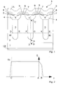
- For example, with reference to figure 1, a multi-drain
MOS power device 3 is described, being formed according to the prior art and comprising a heavily dopedsilicon semiconductor substrate 1 of a first type of conductivity, in particular of the N+ type, whereon a semiconductorepitaxial layer 2 of the same N type is formed. - The
epitaxial layer 2 forms a drain layer common by a plurality of elementary units forming theMOS power device 3. Each elementary unit comprises abody region 4 of a second type of conductivity, in particular of the P type, formed in theepitaxial layer 2. - In the
epitaxial layer 2, below eachbody region 4, there is acolumn region 5 of the P type which extends downwards for the whole thickness of theepitaxial layer 2 towards thesemiconductor substrate 1. - In particular, each
column region 5 is aligned and in contact with arespective body region 4. - The
MOS power device 3 also exhibits, outside thebody regions 4, heavily dopedsource regions 6 of the N type. - The surface of the
epitaxial layer 2 is then covered with a thingate oxide layer 7 and with apolysilicon layer 8. Openings are thus provided in thepolysilicon layer 8 and in the thingate oxide layer 7 to uncover the surface of theepitaxial layer 2 aligned with eachsource region 6. Aninsulating layer 9 completely covers thepolysilicon layer 8 and it partially covers thesource regions 6, so as to enable a sourcemetallic layer 1A to contact thesource regions 6 and thebody regions 4. A drainmetallic layer 1B is also provided on the lower substrate of thesemiconductor substrate 1. - To form a
device 3 able to withstand a breakdown voltage BV equal to 600 V, a drainepitaxial layer 2 is to be provided formed in silicon with a thickness equal to 60 mm and concentration equal to 2x10¹⁴ at/cm3, while if the drainepitaxial layer 2 is instead formed in silicon carbide, it can have a thickness of only 4 µm and concentration equal to 1x10¹⁶ at/cm3, and thus obtaining a much morecompact device 3. - Moreover in the
devices 3 of the multi-drain type, the presence of thecolumn regions 5 allows to reduce the resistivity of theepitaxial layer 2 without decreasing the breakdown voltage BV of thedevice 3 itself. With this type ofdevices 3 it is thus possible to reach a predetermined breakdown voltage BV with a resistivity of theepitaxial layer 2 lower than that used in conventional MOSFET devices, and, in consequence, to obtain power MOSFET transistors with reduced output resistance Ron. - Figures 2 and 3 show the trend of the electric field E in the
column region 5 of type and along the drainepitaxial layer 2. - In particular, as shown in figure 2, with reference to line II-II of figure 1, it results that the trend of the electric field E is constant and equal to the value of the critical electric field Ec in correspondence with a longitudinal dimension of the column region 5 (points A and C of figures 1 and 2).
- Similarly it occurs that the trend of such critical electric field E is constant and equal to the value of the critical electric field Ec in correspondence with line III-III of figure 1, i.e. in correspondence with a transversal dimension of the
device 3, both of thecolumn regions 5 and in the drainepitaxial layer 2, this allows to obtain, being the drain layer thickness identical, a much higher breakdown voltage BV with respect to a MOS device not having thecolumn region 5. - Moreover, it is known that the output resistance Ron is proportional to the resistivity ρepi and to the thickness thepi of the
epitaxial layer 2 while it is inversely proportional to the conduction area Acond, which, for multi-drain transistors, is equal to the active area of thedevice 3 decreased of the area occupied by thecolumn regions 5. - These three parameters, and in particular the resistivity ρepi, in
multi-drain MOS devices 3 are lower with respect to those of conventional power devices. Therefore, the output resistance Ron of thesedevices 3 of the multi-drain type is lower than that of conventional power devices. - Moreover, it is well known that for forming any electronic device integrated on a silicon carbide substrate it is necessary to introduce dopant elements which produce, inside the lattice matrix of the silicon carbide substrate, doped regions of the N or P type.
- In particular, nitrogen (N) and phosphorus (P) introduce donors into the lattice matrix forming doped regions of the N type, while boron (B) and aluminium (Al) introduce acceptors and form doped regions of the P type.
- A particularly important technological problem linked to the formation of such doped regions is that any type of dopant implanted into a silicon carbide substrate has negligible diffusion coefficient D up to temperatures in the order of 1800 °C as described in the article "Properties of Silicon Carbide" by Gary L. Harris.
- In particular, at such high temperatures, nitrogen has a diffusion coefficient D in the silicon carbide equal to 5x10-12 cm2s-1, oxygen has a diffusion coefficient D equal to 1.5x10⁻¹⁶ cm2s-1, while boron has a diffusion coefficient D equal to 2.5x10⁻¹³ cm2s-1.
- In the silicon instead the boron has a diffusion coefficient D equal to 2.5x10⁻¹³ cm2s-1 at a temperature of about 1150 °C and thus it approximately has the same diffusion with respect to a silicon carbide substrate at a much lower temperature.
- The diffusion of dopant species, used for forming the doped regions necessary for the formation of power electronic devices, is thus a problematic technical factor in case silicon carbide substrates are used.
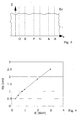
- Finally, analyses carried out by the Applicant have highlighted that the range projected by the boron into the silicon carbide, i.e. the typical distance covered by the boron inside the silicon carbide for a determined implantation energy, increases almost linearly with the implant energy, as shown in figure 4.
- The technical problem underlying the present invention is that of devising a method for forming a power device integrated on a silicon carbide semiconductor substrate, having such structural characteristics as to allow to obtain electronic devices with very contained dimensions and exhibiting a very low output voltage, overcoming the limits and the drawbacks still affecting the devices formed according to the prior art.
- The solution idea underlying the present invention is that of manufacturing a power MOS transistor integrated on a forbidden wide band semiconductor substrate comprising body regions below which column regions are formed obtained with forbidden wide band semiconductor portions formed in the substrate.
- Advantageously, the doped regions of the power MOS transistors are defined, in depth and concentration, by localising dopant elements in the semiconductor substrate by means of suitable ion implants and without making use of diffusion thermal processes.
- On the basis of such solution idea the technical problem is solved by a method as previously indicated and defined by the characterising part of
claim 1. - The problem is also solved by a device as previously indicated and defined by the characterising part of
claim 13. - The characteristics and the advantages of the method and of the device according to the invention will be apparent from the following description of an embodiment thereof given by way of indicative and non limiting example with reference to the annexed drawings.
- In such drawings:
- figure 1 shows a vertical section of a power MOSFET transistor integrated in a semiconductor substrate, formed according to the prior art,
- figure 2 shows the electric field progress along a section II-II of the device of figure 1,
- figure 3 shows the electric field progress along a section III-III of the device of figure 1,
- figure 4 shows the progress of the range projected by the boron ions in a silicon carbide semiconductor substrate when the implant energy varies,
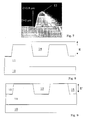
- figures 5 to 14 show vertical sections of a MOSFET transistor during different manufacturing steps of the method according to the invention.
- With reference to such figures, a method is described for manufacturing electronic devices integrated on a semiconductor substrate.
- The method steps hereafter described do not form a complete flow of the process for the manufacturing of integrated circuits. The present invention can be put into practice together with the techniques for manufacturing integrated circuits currently used in the field, and only those commonly used process steps being necessary for the comprehension of the present invention are included in the description.
- The figures showing transversal sections of an integrated electronic device portions during the manufacturing are not drawn to scale, but they are instead drawn so as to show the important characteristics of the invention.
- With reference to figures 5 to 14, a method according to the invention for manufacturing a multi-drain vertical power MOSFET transistor is described.
- On a
semiconductor substrate 10, for example of silicon carbide 4H of a first type of conductivity, in particular of the N type, a firstsuperficial semiconductor layer 11 is formed, for example also of silicon carbide grown by epitaxy. - Advantageously, the
first semiconductor substrate 11 has such a thickness X that the final device can withstand a breakdown voltage equal to 600 V, for example equal to 4 µm, with a concentration comprised for example between 9x10¹⁴ at/cm3 e 5x10¹⁶ at/cm3. - On the
first semiconductor layer 11, afirst mask 12 is formed, for example comprising strips having a width A and placed at a distance B from one another and having a thickness C. The width A is for example equal to 3 µm and the distance B is equal to 3 µm while the thickness is equal to 3 µm. - An etching step is then carried out of the
first semiconductor layer 11, for example of the dry type for forming trench regions in thesemiconductor layer 11. - Advantageously, the
trench regions 13 have tapered walls and they have a depth D equal to, for example, 2,5 µm. - In particular, in the embodiment shown in figure 7, after the etching step of the
first semiconductor layer 11, the depth of thetrench regions 13 is equal to 2 µm, the thickness of thefirst mask 12 is equal to 0,8 µm, while the side walls of thetrench regions 13 thus obtained have an inclination with respect to a bottom surface thereof equal to 70°. - Once the
first mask 12 is removed, thetrench regions 13 are filled in, for example by growth of asecond semiconductor layer 14 of a second type of conductivity, in particular of the P type, for example also in silicon carbide, with a concentration comprised between 2x10¹⁵ at/cm3 e 2x10¹⁷ at/cm3. - Such
second semiconductor layer 14 possibly covers also the wholefirst semiconductor layer 11 of the N type. - For example, after the growth step of the
second semiconductor layer 14, its highest thickness, i.e. the distance E between the bottom surface of thetrench regions 13 and the upper surface of thesecond semiconductor layer 14 of the P type, is equal to 3 µm. - Advantageously, the
second semiconductor layer 14 of the P type has a charge concentration which compensates an N charge concentration which forms thefirst semiconductor layer 11. - A chemical-mechanical cleaning step is then carried out for removing a surface portion of the
second semiconductor layer 14 of the P type until surface portions of thefirst semiconductor layer 11 are exposed, as shown in figure 9. - According to the invention, in the
first semiconductor layer 11 of the Ntype semiconductor portions 15 of the P type are then formed, with a thickness E' for example equal to 2.2 µm. - At this point, on the
first semiconductor layer 11 of the N type and aligned with thesemiconductor portions 15 of the P type, a power vertical MOS transistor is formed for example of the multi-drain type. - For example, as shown in figure 10, on the
first semiconductor layer 11, afirst dielectric layer 16 is formed, for example by means of deposition of about 5000 Å of TEOS, or growth of a thin silicon oxide layer followed by a deposition of silicon nitride of about 1000 Å and by one of TEOS of about 5000 Å. - By means of a photolithographic process including the use of a resist
mask 17, elementary strips are defined in the resistmask 17 with a thickness S for example equal to 4 µm. - The
dielectric layer 16 is then selectively etched for forming thick dielectric strips of width G, spaced from one another by a distance H, always indicated with 16. Such dielectric strips 16 are formed on portions of thefirst semiconductor layer 11 wherein there are nosemiconductor regions 15. - Advantageously, the side walls of the thick dielectric strips 16 are aligned to the
semiconductor portions 15 thus, their width H is equal to the width A of the strips composing thefirst mask 12. - Such dielectric strips 16 act as a screening structure for portions of the
first semiconductor layer 11 during successive implantation steps. - Nothing forbids that the portions of the
first semiconductor layer 11 left exposed by thedielectric strips 16 have a different shape with respect to those of elementary strips and are of polygonal shape or of other suitable shape. - The method according to the invention goes on, thus as shown in figure 11, with a first ion implantation, for example of the P type, suitable to form a
first portion 18 of a body well 19 for the formation of the channel region aligned to thesemiconductor portions 15. - Such first ion implantation of the P type is formed for example with boron or aluminium ions and with a concentration which varies between 1x10¹³ at/cm2 and 1x10¹⁴ at/cm2 and an implant energy 30-80 keV.
- Advantageously, at this point of the method according to the invention, a second ion implantation step of the P type is carried out suitable to form a second
deep portion 20 of the body well 19 to withstand a suitable electric field during the cut-off step and to reduce the gain of parasite transistors which are formed in thefirst semiconductor layer 11. In particular, this seconddeep portion 20 of the body well 19 is aligned to thefirst portion 18 and it is formed at a greater depth. Such second ion implantation of the P type is then carried out for example with boron or aluminium ions with a concentration which varies between 5x10¹³ at/cm2 and 5x10¹⁴ at/cm2 and an implant energy 300-500 keV. - Once the resist
mask 17 is removed, a deposition or growth step is advantageously carried out of a stopping layer for a successive etching, for example 50-500 Å of silicon oxide or nitride, not shown in the figures. - A sacrificial layer of suitable thickness is then deposited for the formation of
implant spacers 19, for example 3000-7000 Å of polysilicon, as shown in figure 11. It is to be noted that the thickness of the sacrificial layer determines the channel length of the MOS device, as it will be clear hereafter. - An etching step is then formed, for example of the dry type, of the sacrificial layer to form spacers 21 on the side walls of the thick dielectric strips 16, as shown in figure 11.
- Advantageously, by means of a photolithographic process which includes the use of a second resist
mask 22, the wholefirst semiconductor layer 11 is covered except for areas aligned to the portions of thesemiconductor layer 11 wherein source regions will be formed. - A first ion implantation step of the N type is then carried out suitable to form a
source region 23 inside thebody region 19. Such first ion implantation of the N type is formed for example with phosphorus, nitrogen or aluminium ions with a concentration which varies between 5x10¹⁴ at/cm2 and 5x10¹⁵ at/cm2 and an implant energy 30-80 keV. - Once a removal step of the
implant spacers 21 is carried out, for example in wet by dipping, into a solution of KOH, advantageously, according to the invention, a single activation thermal process of the dopant species is carried out for completing the implantedregions - Such activation thermal process is carried out at a temperature, for example comprised between 1400 and 1600 °C, for a time comprised between 15 min and 5 hours. It is to be underlined the fact that such activation thermal process is carried out so as to allow only the activation and not the diffusion of the dopant species, in particular it is a process with low thermal budget.
- An etching and removal step of the stopping layer, if previously formed, is then carried out.
- Advantageously according to the invention, as shown in figure 12, the method thus comprises an etching step, for example of the timed wet type, of the thick dielectric strips 16 so as to reduce their width from H to H1 and thus make them go back with respect to the body well 23.
- Once a cleaning step of the surface of the device is carried out, a
thin dielectric layer 24 is formed on the whole device, for example a silicon oxide layer followed by a deposition of 500-1000 Å of TEOS, as shown in figure 13. - A
conductive layer 25 is then formed, for example of suitably doped polysilicon, for the formation ofgate structures 26. - By means of a photolithographic process which includes the use of a third resist mask and successive etching step of the
conductive layer 25 and of the dielectric layer 24 agate loop 26 is thus defined, as shown in figure 13, so that thegate structures 26 are partially overlapped onto thebody wells 19 and insulated therefrom by means of thethin dielectric layer 24 and are thus substantially aligned to thesource regions 23. - In such way, in the final device the
gate structures 26 are insulated from thesemiconductor layer 11 by means of adielectric layer strips 16 having a first thickness and by a second portion formed by thedielectric layer 24 of a second thickness lower than the first thickness. - The device is then completed by means of conventional process steps including:
- a covering step with a
dielectric layer 27 wherein openings are formed for the contacts as shown in figure 14; - a formation step of a
metallization layer 28 and thus a finishing one of the back ofsubstrate 10. - Although in the description reference has been made to silicon carbide semiconductor layers, the method according to the invention can be validly used for forming power MOS devices integrated on semiconductor substrates formed in semiconductor materials with forbidden wide band, i.e. with a forbidden band energetic value Eg greater than that of the silicon which is equal to 1.1 eV. In fact, such power MOS devices formed with semiconductor materials having wide band can withstand a critical electric field Ec higher than 1x10⁶ V/cm and thus a high breakdown voltage BV.
- Therefore, such power MOS devices are also advantageously able to manage high voltages, still maintaining a particularly contained thickness of the drain layer.
- In particular, the manufacturing method according to the invention allows to form power devices integrated on a silicon carbide substrate able to withstand a higher breakdown voltage BV (higher than 600 V) with respect to that of the devices formed according to the prior art.
- In conclusion, the device thus formed is a power MOS transistor of the multi-drain type which is compact and which exhibits a very low output voltage, wherein the
semiconductor layer 11 forms a drain layer common by a plurality of elementary units forming the final MOS power device. Each elementary unit comprises a body well 19 below which thesemiconductor regions 15 are formed which realise, for the final device, the same characteristics of the column regions formed in the power transistors described with reference to the prior art.
Claims (20)
- Method for manufacturing a vertical power MOS transistor on a semiconductor substrate (10) with forbidden wide band comprising a first superficial semiconductor layer (11) with forbidden wide band of a first type of conductivity, the method being characterised in that it comprises the steps of:- forming trench regions (13) in said first superficial semiconductor layer (11),- filling in said trench regions (13) by means of a second semiconductor layer (14) with forbidden wide band of a second type of conductivity, so as to form semiconductor portions (15) of said second type of conductivity contained in said first superficial semiconductor layer (11),- carrying out at least one ion implantation of a first type of dopant in said semiconductor portions (15) for forming respective implanted body regions (19) of said second type of conductivity,- carrying out at least one ion implantation of a second type of dopant in each of said implanted body regions (19) for forming at least one implanted source region (23) of said first type of conductivity inside said implanted body regions (19),- carrying out an activation thermal process of said first and second type of dopant with low thermal budget suitable to complete said formation of said implanted body and source regions (19, 23).
- Method according to claim 1, characterised in that before forming said implanted body regions (19), on said superficial semiconductor layer (11) a screening structure (16) is formed comprising at least one dielectric layer (16) which leaves exposed said semiconductor portions (15) formed in said superficial semiconductor layer (11).
- Method according to claim 1, characterised in that said at least one ion implantation of said first type of dopant comprises at least one first implantation for forming a first portion (18) of said implanted body regions (19).
- Method according to claim 3, characterised in that said at least one ion implantation of said first type of dopant comprises at least one further implantation step for forming a second deeper portion (20) with respect to said portion (18) of said implanted body regions (19).
- Method according to claim 3, characterised in that said first ion implantation of said first type of dopant is carried out with boron or aluminium ions with a concentration which varies between 1x10¹³ at/cm2 and 1x10¹⁴ at/cm2 and an implant energy which varies between 30 and 80 keV.
- Method for manufacturing electronic devices according to claim 4, characterised in that said at least a further implantation step of said first type of dopant is formed with boron or aluminium ions with a concentration which varies between 5x10¹³ at/cm2 and 5x10¹⁴ at/cm2 and an implant energy which varies between 300 and 500 keV.
- Method according to claim 1, characterised in that said activation thermal process of said first and second type of dopant occurs at temperatures lower than 1600°C.
- Method according to claim 2, characterised in that spacers (21) are formed on side walls of said screening structure (16), before carrying out said ion implantation of said second type of dopant.
- Method according to claim 8, characterised in that it comprises the following steps:- etching said screening structure (16) so as to reduce its dimensions and make it go back with respect to said at least a first implanted body region (19),- forming, in cascade, a thin dielectric layer (24) and a conductive layer (22),- forming gate structures (26), by means of a conventional photolithographic technique, by etching, in succession, said conductive layer (25) and said thin dielectric layer (24) so that said gate structures (23) are partially overlapped onto said implanted body regions (19) insulated from said implanted body regions (19) by means of said thin dielectric layer (24), said gate structures (26) being substantially aligned to said at least one implanted source region (23).
- Method according to claim 1, characterised in that before carrying out said ion implantation of a second type of dopant a mask (22) is formed on said superficial semiconductor layer (11) for screening some of said semiconductor portions (15).
- Method according to claim 1, characterised in that said first and second semiconductor layers (11, 14) have grown epitaxially.
- Method according to claim 1, characterised in that said semiconductor substrate (10), said first and second semiconductor layers (11, 14) are formed by silicon carbide layers.
- Method according to claim 12, characterised in that said first semiconductor layer (11) has a concentration comprised between 9x10¹⁴ at/cm3 and 5x10¹⁶ at/cm3 and said second semiconductor layer (14) has a concentration comprised between 2x10¹⁵ at/cm3 and 2x10¹⁷ at/cm3.
- Method according to claim 1, characterised in that said second semiconductor layer (14) of the second type of conductivity has a charge concentration which compensates a charge concentration of the first type of conductivity forming said first semiconductor layer (11).
- Vertical power MOS device integrated on a semiconductor substrate (10, 11) with forbidden wide band comprising at least an implanted body region (19) of a first type of conductivity, at least an implanted source region (23) of a second type of conductivity formed inside said at least one implanted body region (19), a gate structure (26) projecting from said substrate (10, 11) and insulated therefrom by means of a dielectric layer (16, 24), characterised in that below said at least an implanted body region (19) is formed in a semiconductor portion (15) with forbidden wide band of said first type of conductivity formed on said semiconductor substrate (10, 11).
- Power MOS device according to claim 15, characterised in that said semiconductor portion (15) is formed by epitaxial growth.
- Power MOS device according to claim 15, characterised in that said implanted body regions and source regions (19, 23) are obtained only by means of successive implantation steps and an activation thermal process.
- Power MOS device according to claim 15, characterised in that said dielectric layer (16, 24) comprises a first portion (16) of a first thickness and a second portion (24) of a second thickness lower than said first thickness, said gate structure (26) being partially overlapped onto said implanted body region (19) and insulated therefrom by means of said portion (24) of said dielectric layer (16, 24) and substantially aligned to said at least an implanted source region (23).
- Power MOS device according to claim 15, characterised in that said implanted body region (19) and said semiconductor portion (15) are formed in a first semiconductor layer (11) with wide band formed on said semiconductor substrate (10).
- Power MOS device according to claim 15, characterised in that said semiconductor substrate (10), said first semiconductor (11) and said semiconductor portion (15) are of silicon carbide.
Priority Applications (5)
| Application Number | Priority Date | Filing Date | Title |
|---|---|---|---|
| EP05425495A EP1742249A1 (en) | 2005-07-08 | 2005-07-08 | Power field effect transistor and manufacturing method thereof |
| PCT/EP2006/006675 WO2007006507A1 (en) | 2005-07-08 | 2006-07-07 | Power field effect transistor and manufacturing method thereof |
| TW095124809A TW200709305A (en) | 2005-07-08 | 2006-07-07 | Method for manufacturing electronic devices integrated in a semiconductor substrate and corresponding devices |
| US11/971,155 US7871880B2 (en) | 2005-07-08 | 2008-01-08 | Method for manufacturing electronic devices integrated in a semiconductor substrate and corresponding devices |
| US12/964,579 US8174076B2 (en) | 2005-07-08 | 2010-12-09 | Method for manufacturing electronic devices integrated in a semiconductor substrate and corresponding devices |
Applications Claiming Priority (1)
| Application Number | Priority Date | Filing Date | Title |
|---|---|---|---|
| EP05425495A EP1742249A1 (en) | 2005-07-08 | 2005-07-08 | Power field effect transistor and manufacturing method thereof |
Publications (1)
| Publication Number | Publication Date |
|---|---|
| EP1742249A1 true EP1742249A1 (en) | 2007-01-10 |
Family
ID=36091409
Family Applications (1)
| Application Number | Title | Priority Date | Filing Date |
|---|---|---|---|
| EP05425495A Ceased EP1742249A1 (en) | 2005-07-08 | 2005-07-08 | Power field effect transistor and manufacturing method thereof |
Country Status (4)
| Country | Link |
|---|---|
| US (2) | US7871880B2 (en) |
| EP (1) | EP1742249A1 (en) |
| TW (1) | TW200709305A (en) |
| WO (1) | WO2007006507A1 (en) |
Cited By (3)
| Publication number | Priority date | Publication date | Assignee | Title |
|---|---|---|---|---|
| EP1962330A2 (en) | 2007-02-23 | 2008-08-27 | Denso Corporation | Method for manufacturing SIC semiconductor device |
| CN102623318A (en) * | 2011-01-31 | 2012-08-01 | 瑞萨电子株式会社 | Semiconductor device and manufacturing method thereof |
| WO2016202786A1 (en) * | 2015-06-16 | 2016-12-22 | Ascatron Ab | Sic superjunction structures |
Families Citing this family (7)
| Publication number | Priority date | Publication date | Assignee | Title |
|---|---|---|---|---|
| EP1742249A1 (en) * | 2005-07-08 | 2007-01-10 | STMicroelectronics S.r.l. | Power field effect transistor and manufacturing method thereof |
| US20100314695A1 (en) * | 2009-06-10 | 2010-12-16 | International Rectifier Corporation | Self-aligned vertical group III-V transistor and method for fabricated same |
| JP5616665B2 (en) * | 2010-03-30 | 2014-10-29 | ローム株式会社 | Semiconductor device |
| CN103021856A (en) * | 2011-09-28 | 2013-04-03 | 比亚迪股份有限公司 | Method for forming semiconductor structure with super junctions and semiconductor structure |
| CN103578983A (en) * | 2012-08-01 | 2014-02-12 | 无锡华润上华半导体有限公司 | Field stop type insulated gate bipolar transistor and manufacturing method thereof |
| WO2014115280A1 (en) * | 2013-01-24 | 2014-07-31 | トヨタ自動車株式会社 | Semiconductor device and production method for semiconductor device |
| CN111200025A (en) * | 2018-11-20 | 2020-05-26 | 深圳尚阳通科技有限公司 | Superjunction device and method of making the same |
Citations (6)
| Publication number | Priority date | Publication date | Assignee | Title |
|---|---|---|---|---|
| US4672407A (en) * | 1984-05-30 | 1987-06-09 | Kabushiki Kaisha Toshiba | Conductivity modulated MOSFET |
| US5510281A (en) * | 1995-03-20 | 1996-04-23 | General Electric Company | Method of fabricating a self-aligned DMOS transistor device using SiC and spacers |
| US6048759A (en) * | 1998-02-11 | 2000-04-11 | Magepower Semiconductor Corporation | Gate/drain capacitance reduction for double gate-oxide DMOS without degrading avalanche breakdown |
| EP1111685A1 (en) * | 1999-12-09 | 2001-06-27 | Hitachi, Ltd. | Power semiconductor device |
| US6313482B1 (en) * | 1999-05-17 | 2001-11-06 | North Carolina State University | Silicon carbide power devices having trench-based silicon carbide charge coupling regions therein |
| JP2003229569A (en) * | 2002-01-31 | 2003-08-15 | Fuji Electric Co Ltd | Method for manufacturing super junction semiconductor device |
Family Cites Families (5)
| Publication number | Priority date | Publication date | Assignee | Title |
|---|---|---|---|---|
| EP1009036B1 (en) * | 1998-12-09 | 2007-09-19 | STMicroelectronics S.r.l. | High-voltage MOS-gated power device, and related manufacturing process |
| US7067363B2 (en) * | 2002-12-30 | 2006-06-27 | Stmicroelectronics S.R.L. | Vertical-conduction and planar-structure MOS device with a double thickness of gate oxide and method for realizing power vertical MOS transistors with improved static and dynamic performances and high scaling down density |
| JP4939760B2 (en) * | 2005-03-01 | 2012-05-30 | 株式会社東芝 | Semiconductor device |
| EP1742249A1 (en) * | 2005-07-08 | 2007-01-10 | STMicroelectronics S.r.l. | Power field effect transistor and manufacturing method thereof |
| EP1742250A1 (en) * | 2005-07-08 | 2007-01-10 | STMicroelectronics S.r.l. | Power field effect transistor and manufacturing method thereof |
-
2005
- 2005-07-08 EP EP05425495A patent/EP1742249A1/en not_active Ceased
-
2006
- 2006-07-07 TW TW095124809A patent/TW200709305A/en unknown
- 2006-07-07 WO PCT/EP2006/006675 patent/WO2007006507A1/en not_active Ceased
-
2008
- 2008-01-08 US US11/971,155 patent/US7871880B2/en active Active
-
2010
- 2010-12-09 US US12/964,579 patent/US8174076B2/en active Active
Patent Citations (6)
| Publication number | Priority date | Publication date | Assignee | Title |
|---|---|---|---|---|
| US4672407A (en) * | 1984-05-30 | 1987-06-09 | Kabushiki Kaisha Toshiba | Conductivity modulated MOSFET |
| US5510281A (en) * | 1995-03-20 | 1996-04-23 | General Electric Company | Method of fabricating a self-aligned DMOS transistor device using SiC and spacers |
| US6048759A (en) * | 1998-02-11 | 2000-04-11 | Magepower Semiconductor Corporation | Gate/drain capacitance reduction for double gate-oxide DMOS without degrading avalanche breakdown |
| US6313482B1 (en) * | 1999-05-17 | 2001-11-06 | North Carolina State University | Silicon carbide power devices having trench-based silicon carbide charge coupling regions therein |
| EP1111685A1 (en) * | 1999-12-09 | 2001-06-27 | Hitachi, Ltd. | Power semiconductor device |
| JP2003229569A (en) * | 2002-01-31 | 2003-08-15 | Fuji Electric Co Ltd | Method for manufacturing super junction semiconductor device |
Non-Patent Citations (1)
| Title |
|---|
| VATHULYA V R ET AL: "CHARACTERIZATION OF INVERSION AND ACCUMULATION LAYER ELECTRON TRANSPORT IN 4H AND 6H-SIC MOSFETS ON IMPLANTED P-TYPE REGIONS", IEEE TRANSACTIONS ON ELECTRON DEVICES, IEEE, PISCATAWAY, NJ, US, vol. 47, no. 11, November 2000 (2000-11-01), pages 2018 - 2023, XP000970474, ISSN: 0018-9383 * |
Cited By (6)
| Publication number | Priority date | Publication date | Assignee | Title |
|---|---|---|---|---|
| EP1962330A2 (en) | 2007-02-23 | 2008-08-27 | Denso Corporation | Method for manufacturing SIC semiconductor device |
| EP1962330A3 (en) * | 2007-02-23 | 2009-04-01 | Denso Corporation | Method for manufacturing SIC semiconductor device |
| CN102623318A (en) * | 2011-01-31 | 2012-08-01 | 瑞萨电子株式会社 | Semiconductor device and manufacturing method thereof |
| EP2482308A3 (en) * | 2011-01-31 | 2015-01-07 | Renesas Electronics Corporation | Semiconductor device and manufacturing method thereof |
| CN102623318B (en) * | 2011-01-31 | 2016-03-09 | 瑞萨电子株式会社 | Semiconductor device and manufacture method thereof |
| WO2016202786A1 (en) * | 2015-06-16 | 2016-12-22 | Ascatron Ab | Sic superjunction structures |
Also Published As
| Publication number | Publication date |
|---|---|
| US20080185594A1 (en) | 2008-08-07 |
| US20110079794A1 (en) | 2011-04-07 |
| US7871880B2 (en) | 2011-01-18 |
| WO2007006507A1 (en) | 2007-01-18 |
| US8174076B2 (en) | 2012-05-08 |
| TW200709305A (en) | 2007-03-01 |
Similar Documents
| Publication | Publication Date | Title |
|---|---|---|
| US8174076B2 (en) | Method for manufacturing electronic devices integrated in a semiconductor substrate and corresponding devices | |
| US7892923B2 (en) | Power field effect transistor and manufacturing method thereof | |
| US11245016B2 (en) | Silicon carbide trench semiconductor device | |
| KR101900843B1 (en) | Trench power MOSFET with reduced on-resistance | |
| US7094640B2 (en) | Method of making a trench MOSFET device with improved on-resistance | |
| US20120018800A1 (en) | Trench Superjunction MOSFET with Thin EPI Process | |
| US20020086472A1 (en) | Technique to obtain high mobility channels in MOS transistors by forming a strain layer on an underside of a channel | |
| JP4669191B2 (en) | Horizontal superjunction semiconductor device | |
| US7713853B2 (en) | Method for manufacturing electronic devices integrated in a semiconductor substrate and corresponding devices | |
| US20110198689A1 (en) | Semiconductor devices containing trench mosfets with superjunctions | |
| US7601568B2 (en) | MOS transistor and method for producing a MOS transistor structure | |
| US8129778B2 (en) | Semiconductor devices and methods for making the same | |
| US11158705B2 (en) | Method for forming a superjunction transistor device | |
| WO2023278794A2 (en) | Silicon carbide power device with an enhanced junction field effect transistor region | |
| US20220285488A1 (en) | Superjunction semiconductor device having floating region and method of manufacturing same | |
| JP7787037B2 (en) | Semiconductor device and manufacturing method thereof | |
| US6541318B2 (en) | Manufacturing process of a high integration density power MOS device | |
| US7205657B2 (en) | Complimentary lateral nitride transistors | |
| CN113517334A (en) | A kind of power MOSFET device with high-K dielectric trench and preparation method thereof |
Legal Events
| Date | Code | Title | Description |
|---|---|---|---|
| PUAI | Public reference made under article 153(3) epc to a published international application that has entered the european phase |
Free format text: ORIGINAL CODE: 0009012 |
|
| AK | Designated contracting states |
Kind code of ref document: A1 Designated state(s): AT BE BG CH CY CZ DE DK EE ES FI FR GB GR HU IE IS IT LI LT LU LV MC NL PL PT RO SE SI SK TR |
|
| AX | Request for extension of the european patent |
Extension state: AL BA HR MK YU |
|
| 17P | Request for examination filed |
Effective date: 20070706 |
|
| 17Q | First examination report despatched |
Effective date: 20070802 |
|
| AKX | Designation fees paid |
Designated state(s): DE FR GB IT |
|
| RAP1 | Party data changed (applicant data changed or rights of an application transferred) |
Owner name: STMICROELECTRONICS SRL |
|
| RAP1 | Party data changed (applicant data changed or rights of an application transferred) |
Owner name: STMICROELECTRONICS SRL |
|
| STAA | Information on the status of an ep patent application or granted ep patent |
Free format text: STATUS: THE APPLICATION HAS BEEN REFUSED |
|
| 18R | Application refused |
Effective date: 20120315 |