EP1742041A1 - Cost-effective multi-sensorial surface inspection - Google Patents
Cost-effective multi-sensorial surface inspection Download PDFInfo
- Publication number
- EP1742041A1 EP1742041A1 EP06013670A EP06013670A EP1742041A1 EP 1742041 A1 EP1742041 A1 EP 1742041A1 EP 06013670 A EP06013670 A EP 06013670A EP 06013670 A EP06013670 A EP 06013670A EP 1742041 A1 EP1742041 A1 EP 1742041A1
- Authority
- EP
- European Patent Office
- Prior art keywords
- line
- tested
- light sources
- lighting
- different
- Prior art date
- Legal status (The legal status is an assumption and is not a legal conclusion. Google has not performed a legal analysis and makes no representation as to the accuracy of the status listed.)
- Granted
Links
- 238000007689 inspection Methods 0.000 title claims abstract description 22
- 230000007547 defect Effects 0.000 claims abstract description 36
- 238000005286 illumination Methods 0.000 claims abstract description 34
- 238000000034 method Methods 0.000 claims abstract description 22
- 230000001360 synchronised effect Effects 0.000 claims abstract description 7
- 238000001514 detection method Methods 0.000 claims description 10
- 238000011156 evaluation Methods 0.000 claims description 9
- 230000003287 optical effect Effects 0.000 claims description 7
- 238000003672 processing method Methods 0.000 claims description 5
- 238000004519 manufacturing process Methods 0.000 claims description 4
- 230000003213 activating effect Effects 0.000 claims description 3
- 230000002349 favourable effect Effects 0.000 claims description 3
- 239000004065 semiconductor Substances 0.000 claims description 2
- 238000001228 spectrum Methods 0.000 abstract 1
- 206010039737 Scratch Diseases 0.000 description 4
- 208000002352 blister Diseases 0.000 description 4
- 230000001960 triggered effect Effects 0.000 description 3
- 240000006240 Linum usitatissimum Species 0.000 description 2
- 230000007704 transition Effects 0.000 description 2
- 230000003044 adaptive effect Effects 0.000 description 1
- 238000004364 calculation method Methods 0.000 description 1
- 239000000919 ceramic Substances 0.000 description 1
- 238000002845 discoloration Methods 0.000 description 1
- 238000004049 embossing Methods 0.000 description 1
- 238000005516 engineering process Methods 0.000 description 1
- 230000004927 fusion Effects 0.000 description 1
- 238000003384 imaging method Methods 0.000 description 1
- 239000011159 matrix material Substances 0.000 description 1
- 238000003909 pattern recognition Methods 0.000 description 1
- 230000035945 sensitivity Effects 0.000 description 1
- 239000004753 textile Substances 0.000 description 1
Images

Classifications
-
- G—PHYSICS
- G01—MEASURING; TESTING
- G01N—INVESTIGATING OR ANALYSING MATERIALS BY DETERMINING THEIR CHEMICAL OR PHYSICAL PROPERTIES
- G01N21/00—Investigating or analysing materials by the use of optical means, i.e. using sub-millimetre waves, infrared, visible or ultraviolet light
- G01N21/84—Systems specially adapted for particular applications
- G01N21/88—Investigating the presence of flaws or contamination
- G01N21/89—Investigating the presence of flaws or contamination in moving material, e.g. running paper or textiles
- G01N21/8901—Optical details; Scanning details
- G01N21/8903—Optical details; Scanning details using a multiple detector array
Definitions
- Dirt, discoloration, etc. are usually detected under a diffuse illumination with color or b / w cameras.
- Surface damage such as scratches, bumps and impressions, on the other hand, are better detected under directional illumination with b / w cameras in the so-called dark field or bright field.
- the combination of several line scan cameras with a dedicated special lighting is called "multi-sensorial" inspection systems.
- Each of these subregions requires a different lighting / camera arrangement to detect surface defects in this subregion, depending on the grade and defect type. This leads in known multisensorial systems to a very large variety of lighting / camera arrangements and thus at very high costs.
- the lighting angles / angles have been set, they are only valid for a specific surface structure and, in the case of a differently structured product, have to be laboriously reconfigured. These difficulties have so far meant that the inspection of products with a structured topology is not satisfactorily resolved.
- a method for surface inspection of moving products which captures the moving surface to be tested with at least one stationary line scan camera arranged transversely to the movement of the surface.
- line scan camera also means matrix cameras in which only the same line is repeatedly read out repeatedly.
- the line scan camera has a line clock that is at least N times higher than the geometrical size of the defects to be detected.
- Each other illumination configuration of a number of N illumination configurations stroboscopically exposes the surface to be examined synchronized with the line clock, with each of N successive image lines of the line scan camera each being exposed to a different illumination configuration from the N illumination configurations.
- a lighting configuration is formed by selectively enabling or disabling one or more light sources from a number of M light sources.
- the resulting at least N-fold nested image of the surface to be tested is split into at least N individual images. The individual images are evaluated for detecting defects on the surface using automatic image processing methods.
- the N lighting configurations illuminate the surface to be tested, each with different optical characteristics.
- the number M of light sources is less than the number N of illumination configurations.
- N lighting configurations can be formed from only M light sources, further contributing to the cost reduction.
- the light sources are formed of semiconductor light sources. It is thus created a low-cost lighting that allows the detection of different errors.
- the evaluation of the N individual images is preferably automatically weighted differently depending on the surface region, the knowledge of local topology and local optical properties of the product surface being used from production data being used. It is thus possible, e.g. to use the knowledge contained in the CAD design to perform the optical inspection in spite of spatially complicated surfaces with simple means.
- the prior knowledge of the geometry of the surface to be inspected that is present in such products can thus be used purposefully to evaluate only those image lines from the N-times taken image lines, which originate from a type of illumination which makes errors visible, which are present in the image field the line camera surface profile are located, ie to prefer that illumination channel in the evaluation, which illuminates this region in the sense of error detection at the lowest.
- the remaining image lines can not be evaluated at all.
- Such methods of different weighting of signals when viewing multiple signals are known to those skilled in pattern recognition and therefore need not be further described.
- Such a regionally adaptive weighting makes it possible, for example, to effectively reduce misdetections due to thresholds that are too low, and thus to balance the dangers of high surface quality in the surface inspection Detection sensitivity and the risk of erroneous over detection significantly easier. This means, in particular for the operator of such a system, a considerable facilitation in the setting of the detection thresholds.
- the invention further provides an arrangement which permits surface inspection of moving products. It comprises at least one line camera arranged transversely to the movement of the surface, with a line clock that is at least N times higher than the geometrical size of the defects to be detected. A number of M light sources can expose the surface to be tested, each with different optical characteristics.
- the arrangement further includes a switching device that, in synchronization with the line clock, turns on a different lighting configuration of N lighting configurations by selectively activating or deactivating one or more of the M light sources. As a result of this synchronization, successive picture lines are respectively recorded under different exposure conditions and interlaced pictures are formed.
- the arrangement further comprises a device for splitting the resulting at least N-fold nested image of the surface to be tested into at least N individual images and a device for evaluating the individual images for detecting defects on the surface using automatic image processing methods.
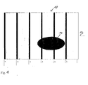
- Fig. 1 shows schematically the surface 10 of a specimen moving in the image to the right, as indicated by an arrow 12. On the surface there is a defect or defect 14.
- the surface is inspected with a line scan camera while illuminating the surface in accordance with the defects to be detected.
- the frequency or clock rate with which the line scan camera is triggered is calculated from the transport speed of the product to be tested and the smallest error to be detected.
- the image excerpts obtained with the line scan camera are indicated by the bars A, wherein the schematic representation in FIG. 1 does not permit any statement about the width of the area actually detected by the camera.
- the bars A in Fig. 1 thus have a distance of 1 mm from each other in the example.
- the approximately 2 mm defect 14 is reliably detected with two pixels.
- the product width is 1000 mm.
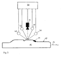
- FIG. 2 shows an inventive arrangement for surface inspection.
- a furniture front 16 has the height profile shown in Fig. 2: flat regions at different heights alternate with transitions and chamfers different slopes and with recessed gutter-shaped depressions.
- the furniture front 16 moves transversely to a line camera 18 at a speed v in the image from left to right as indicated by arrow 12.
- a total of 4 stroboscopic light sources 20 to 26 are arranged around the line scan camera 18 aligned perpendicular to the furniture front.
- a defect 14, for example a local soiling, is located on a flank sloping to the right in the structured surface 10.
- the light sources 20 to 26 forming the illumination configurations and the line scan camera 18 are connected to a control and evaluation unit 28.
- This control and evaluation unit 28 may consist of several individual devices. It comprises a switching device which, synchronized with the line clock of the line scan camera 18, switches on a respectively different illumination configuration consisting of one of the light sources 20 to 26 or of a group of the light sources 20 to 26. It also comprises a device for splitting the at least N-fold nested image of the surface to be tested into at least N individual images and a device for evaluating the individual images for detecting defects on the surface with automatic image processing methods.
- Each of these illuminations thus alone produces a particularly high visibility for a particular category of errors.
- Some of the lighting configurations such as e.g. By combining both images, D and E create highly visible defects on the planar regions of the profiles by making the shadow cast to the right by a local flaw (Scenario D) combined with the shadow cast to the left (Scenario E) by a local flaw generated in which the errors are clearly visible through a double-sided shadow.
- each stroboscopic illumination configuration illuminates the surface so short that only the currently read image line of the line sensor is exposed.
- the line frequency of the line sensor is chosen so high that the movement of the profile is negligibly small, that is, that each lighting configuration captures very closely adjacent image lines of the moving surface.
- Line scan cameras with a high line frequency of up to 50 kHz are state of the art today and can be obtained cheaply.
- the price for obtaining a surface image with 5 times the amount of information through the use of 5 lighting arrangements adapted to the topology of the furniture front and to the group of lighting defects to be detected is therefore modest.
- no five combined lighting / camera modules with 5 lights each and 5 more cameras are needed.
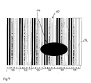
- FIG. 4 shows schematically the 5-fold nested line image of the product surface resulting in the image memory. As shown in FIG. 1, FIG. 4 shows the surface 10 to be tested, which moves in the direction of the arrow 12. On the surface a defect 14 is indicated. Since the line scan camera is operated with a 5-fold higher line frequency, the recording bars A - E follow each other in a more dense sequence, remaining with the example values already used, a new recording is now triggered when the product has moved by only 0.2 mm. Due to the changing with the line frequency illumination, each change the 5 different - each lighting configuration A to E - associated line images.
- N 5 consecutive image lines form a "multisensor image line", which in Fig. 4 by the reference numerals 30 to 40th are designated.
- the N-fold interlaced line image is stored in the form of N individual images in the image computer and these N images are independently evaluated for defects.
- M new multisensor line images are calculated from the multi-sensorial (i.e., N-interleaved) line images stored in the image memory by combining all or a subset of the N line images into new line images.
- E and D denote the lights 20 and 26 turned on in the above example of a 5-stage lighting scenario.
- the images in the described embodiment are weighted differently depending on the lighting scenario and surface condition.
- the brightness defects on left-sloping flanks are weighted more heavily in the images with a light coming from the right than in the remaining, less suitable lighting configurations for this region.
- the weighting can be achieved by a low detection threshold, because in the image with a favorable illumination configuration the defects appear more contrast-rich and thus show a better signal-to-noise ratio than in the unfavorably illuminated images.
- From the CAD description it is known at which points of the furniture front lie to the left inclined surfaces. From the coordinates of the pixels of the line scan camera it can be determined which section in the acquired 2-dimensional N-fold interlaced image corresponds to this region.
- this Region is therefore assigned to the illumination channel "diagonally from the left” a stronger weight in the error detection in the evaluation than the other channels. In extreme cases, this weighting can go so far that only the low-lighted image is evaluated and the remaining 4 images in this region are not evaluated.
- the different weighting of the different illumination channels can be aligned not only according to the height and inclination angle topology, but also according to other local, a-priori known surface properties such as brightness, texture, gloss, etc. as well as the permissible local tolerance and the respective defect class , As a result, it is achieved by way of example that the flaking, which is clearly visible in oblique illumination, is detected at the chamfers, which are clearly visible to the human eye, with a very low tolerance threshold.
- the described application of the inspection of a structured furniture front is to be understood as an example.
- the idea of the invention is directed to all surface inspection tasks, which can be illuminated only inconveniently with a single illumination and in which, for cost reasons, no multiple combination of lighting and black and white camera modules or a costly color camera according to the teaching of EP 0 898 163 B1 can be used.
Landscapes
- Engineering & Computer Science (AREA)
- Textile Engineering (AREA)
- Physics & Mathematics (AREA)
- Health & Medical Sciences (AREA)
- Life Sciences & Earth Sciences (AREA)
- Chemical & Material Sciences (AREA)
- Analytical Chemistry (AREA)
- Biochemistry (AREA)
- General Health & Medical Sciences (AREA)
- General Physics & Mathematics (AREA)
- Immunology (AREA)
- Pathology (AREA)
- Investigating Materials By The Use Of Optical Means Adapted For Particular Applications (AREA)
Abstract
Description
Die automatische Inspektion von Oberflächen in der Produktionslinie zur Erkennung von ästhetischen und physikalischen Qualitätsmängeln ist heute eine eingeführte Technologie für flache Produkte wie textile Bahnen, keramische Fliesen und Bodenbeläge (siehe z.B. www.massen.com; www. isravision.com). Die Bildaufnahme geschieht bei diesen Systemen in der Regel mit Hilfe von Zeilenkameras und unterschiedlichen Beleuchtungseinrichtungen, welche die Produktoberfläche entweder diffus oder aber gerichtet oder aber (bei transparenten Produkten) im Durchlicht beleuchten.The automatic inspection of surfaces in the production line for the detection of aesthetic and physical quality defects is today an established technology for flat products such as textile sheets, ceramic tiles and floor coverings (see eg www.massen.com , www.isravision.com). In these systems, image acquisition usually takes place with the aid of line cameras and different illumination devices, which illuminate the product surface either diffused or directed or, in the case of transparent products, in transmitted light.
Oft werden mehrere unterschiedliche Beleuchtungs-/Kamerasysteme in einer Anlage kombiniert, um die unterschiedlichen Fehler optimal erkennen zu können.Often several different lighting / camera systems are combined in one system in order to be able to optimally recognize the different errors.
Verschmutzungen, Verfärbungen, u.Ä. werden in der Regel unter einer diffusen Beleuchtung mit Farb- oder s/w Kameras erkannt. Oberflächenbeschädigungen wie Kratzer, Beulen und Eindrücke hingegen werden besser unter einer gerichteten Beleuchtung mit s/w Kameras im sog. Dunkelfeld oder Hellfeld detektiert. Die Kombination mehrerer Zeilenkameras mit einer zugeordneten, speziellen Beleuchtung nennt man "multi-sensorielle" Inspektionssysteme.Dirt, discoloration, etc. are usually detected under a diffuse illumination with color or b / w cameras. Surface damage such as scratches, bumps and impressions, on the other hand, are better detected under directional illumination with b / w cameras in the so-called dark field or bright field. The combination of several line scan cameras with a dedicated special lighting is called "multi-sensorial" inspection systems.
Es gibt aber zahlreiche Produkte mit einer nicht-flachen, insbesondere in der Höhe strukturierten Vorderseite wie z.B. Möbelfronten, Garagentore, Essgeschirr, usw. Bei diesen Produkten gibt es Teilregionen mit unterschiedlicher Höhe (bezogen auf die Rückfläche), mit im Raum geneigten Teilflächen, Fasen und Übergängen, oder mit eingepressten Rillen, die zu einer komplexen, dreidimensionalen Topologie führen. Wir bezeichnen diese Oberflächen im Rahmen dieser Anmeldung als "strukturierte Oberflächen" im Vergleich zu den flachen Oberflächen.However, there are numerous products with a non-flat, especially in the height structured front such as furniture fronts, garage doors, dinnerware, etc. These products have subregions of different heights (in relation to the back surface), with part faces, chamfers and transitions sloped in space, or with indented grooves resulting in a complex, three-dimensional topology. For the purposes of this application, we refer to these surfaces as "structured surfaces" in comparison to the flat surfaces.
Jede dieser Teilregionen benötigt je nach Neigung und Fehlertyp eine andere Beleuchtungs-/Kamera-Anordnung zur Erkennung von Oberflächenfehlern in dieser Teilregion. Dies führt bei bekannten multisensoriellen Systemen zu einer sehr großen Vielfalt von Beleuchtungs-/Kamera-Anordnungen und damit zu sehr hohen Kosten. Darüber hinaus sind die einmal eingestellten Beleuchtungswinkel/ Aufnahmewinkel nur für eine bestimmte Oberflächenstruktur gültig und müssen bei einem andersartig strukturierten Produkt umständlich neu eingerichtet werden. Diese Schwierigkeiten haben bisher dazu geführt, dass die Inspektion von Produkten mit strukturierter Topologie nicht zufriedenstellend gelöst ist.Each of these subregions requires a different lighting / camera arrangement to detect surface defects in this subregion, depending on the grade and defect type. This leads in known multisensorial systems to a very large variety of lighting / camera arrangements and thus at very high costs. In addition, once the lighting angles / angles have been set, they are only valid for a specific surface structure and, in the case of a differently structured product, have to be laboriously reconfigured. These difficulties have so far meant that the inspection of products with a structured topology is not satisfactorily resolved.
Es sind technische Lösungen für die Oberflächeninspektion bekannt, die mit einer in der Regel aus einer senkrechten Position aufnehmenden Farbzeilenkamera arbeiten. Unter verschiedenen Winkeln angeordnete, spektral unterschiedlich eingestellte Beleuchtungen belichten dabei die Oberfläche. Auf Grund der drei Farbkanäle der Farbzeilenkamera werden somit gleichzeitig mehrere (i.A. drei) Bilder des gleichen Punktes der Oberfläche aufgenommen. Durch Verrechnung der einzelnen, gleichzeitig entstehenden Bilder können Defekte auch dann noch erkannt werden, wenn sie sich auf unterschiedlicher Höhe oder Neigung der Oberflächen-Topologie befinden (sog. fotometrisches Stereo, siehe z.B.
Diese Lösung ist jedoch durch die Verwendung einer mehrkanaligen Farbzeilenkamera und insbesondere bei großen Produkten durch die hohe geforderte Querauflösung (Anzahl von Bildpunkten pro Zeile) der Farbzeilenkamera sehr teuer. Das Verfahren des fotometrischen Stereos nach
Es besteht daher ein hohes wirtschaftliches Interesse an einer einfachen und kostengünstigen Oberflächeninspektion für strukturierte Oberflächen wie Möbelfronten, Türen usw. mit Hilfe einfacher und kostengünstiger Zeilenkamerasysteme.There is therefore a high economic interest in a simple and inexpensive surface inspection for structured surfaces such as furniture fronts, doors, etc. using simple and inexpensive line scan camera systems.
Es besteht der Bedarf, unabhängig von den lokalen radiometrischen und geometrischen Eigenschaften der zu prüfenden Oberfläche, wie z.B. der lokalen Neigung, der lokalen Krümmung, der lokalen Höhe, der lokalen Reflexionseigenschaften, usw., robust alle ästhetischen und physikalischen Oberflächenfehler in allen Bereichen dieser strukturierten Oberflächen zu erkennen.There is a need, independent of the local radiometric and geometric properties of the surface to be tested, such as e.g. the local inclination, the local curvature, the local height, the local reflection properties, etc., to robustly detect all aesthetic and physical surface defects in all areas of these textured surfaces.
Dies wird erreicht durch ein Verfahren gemäß Anspruch 1 und durch eine Anordnung gemäß Anspruch 9.This is achieved by a method according to claim 1 and by an arrangement according to claim 9.
Es wird ein Verfahren zur Oberflächeninspektion bewegter Produkte zur Verfügung gestellt, das die zu prüfende bewegte Oberfläche mit mindestens einer quer zur Bewegung der Oberfläche angeordneten stationären Zeilenkamera bildhaft erfasst. Unter "Zeilenkamera" werden im Sinne der Erfindung auch Matrixkameras verstanden, bei denen lediglich wiederholt immer wieder die gleiche Zeile ausgelesen wird. Die Zeilenkamera hat einen Zeilentakt, der mindestens N-fach höher ist, als es die geometrische Größe der zu detektierenden Defekte verlangt. Eine jeweils andere Beleuchtungskonfiguration aus einer Anzahl von N Beleuchtungskonfigurationen belichtet die zu prüfende Oberfläche stroboskopisch, synchronisiert mit dem Zeilentakt, wobei von N aufeinander folgenden Bildzeilen der Zeilenkamera jede jeweils mit einer anderen Beleuchtungskonfiguration aus den N Beleuchtungskonfigurationen belichtet wird. Eine Beleuchtungskonfiguration wird gebildet durch selektives Aktivieren oder Deaktivieren einzelner oder mehrerer Lichtquellen aus einer Anzahl von M Lichtquellen. Das entstehende mindestens N-fach verschachtelte Bild der zu prüfenden Oberfläche wird in mindestens N einzelne Bilder aufgespalten. Die Einzelbilder werden zur Erkennung von Defekten auf der Oberfläche mit Verfahren der automatischen Bildverarbeitung ausgewertet.A method for surface inspection of moving products is provided, which captures the moving surface to be tested with at least one stationary line scan camera arranged transversely to the movement of the surface. For the purposes of the invention, "line scan camera" also means matrix cameras in which only the same line is repeatedly read out repeatedly. The line scan camera has a line clock that is at least N times higher than the geometrical size of the defects to be detected. Each other illumination configuration of a number of N illumination configurations stroboscopically exposes the surface to be examined synchronized with the line clock, with each of N successive image lines of the line scan camera each being exposed to a different illumination configuration from the N illumination configurations. A lighting configuration is formed by selectively enabling or disabling one or more light sources from a number of M light sources. The resulting at least N-fold nested image of the surface to be tested is split into at least N individual images. The individual images are evaluated for detecting defects on the surface using automatic image processing methods.
Durch die Erhöhung des Zeilentaktes um das N-fache über die für die gewünschte Auflösung benötigte Taktrate hinaus, wird es möglich, ineinander verschachtelte Bilder zu erzielen. Außerdem werden mehrere und zwar mindestens N Beleuchtungskonfigurationen nacheinander stroboskopisch angeschaltet, synchronisiert mit dem erhöhten Zeilentakt. Damit sind die ineinander verschachtelten Bilder jeweils unter anderen Beleuchtungsbedingungen aufgenommen, ohne dass die Kamera getrennte Farbkanäle benötigt. In einer bevorzugten Ausführungsform wird eine einfache monochromatische und damit kostengünstige Zeilenkamera verwendet und dennoch eine "multi-sensorielle Inspektion" erreicht.By increasing the line clock by N times beyond the clock rate required for the desired resolution, it becomes possible to achieve interlaced images. In addition, several and indeed at least N lighting configurations sequentially stroboscopically switched, synchronized with the increased line clock. Thus, the interlaced images are each taken under different lighting conditions, without the camera needs separate color channels. In a preferred embodiment, a simple monochromatic and therefore cost-effective line scan camera is used and nevertheless a "multi-sensorial inspection" is achieved.
Die N Beleuchtungskonfigurationen beleuchten die zu prüfende Oberfläche mit jeweils unterschiedlicher optischer Charakteristik. Bevorzugter Weise ist die Anzahl M der Lichtquellen kleiner als die Anzahl N der Beleuchtungskonfigurationen. Damit können N Beleuchtungskonfigurationen aus nur M Lichtquellen gebildet werden, was weiter zur Kostenreduzierung beiträgt. Vorzugsweise sind die Lichtquellen aus Halbleiter-Lichtquellen gebildet. Es wird somit eine kostengünstige Beleuchtung geschaffen, die die Detektion unterschiedlicher Fehler erlaubt.The N lighting configurations illuminate the surface to be tested, each with different optical characteristics. Preferably, the number M of light sources is less than the number N of illumination configurations. Thus, N lighting configurations can be formed from only M light sources, further contributing to the cost reduction. Preferably, the light sources are formed of semiconductor light sources. It is thus created a low-cost lighting that allows the detection of different errors.
Bevorzugter Weise wird die Auswertung der N Einzelbilder automatisch je nach Oberflächenregion unterschiedlich gewichtet, wobei das aus Produktionsdaten vorliegende Wissen über lokale Topologie und lokale optische Eigenschaften der Produktoberfläche genutzt wird. Es ist damit möglich, das z.B. in der CAD Konstruktion enthaltene Wissen zu nutzen, um die optische Inspektion trotz räumlich komplizierter Oberflächen mit einfachen Mitteln durchzuführen. Das bei solchen Produkten vorhandene Vorwissen über die Geometrie der zu inspizierenden Oberfläche kann somit gezielt dazu benutzt werden, aus den N-fach aufgenommenen Bildzeilen nur diejenigen Bildzeilen auszuwerten, welche von einer Beleuchtungsart stammen, die Fehler sichtbar macht, welche sich auf dem momentan im Bildfeld der Zeilenkamera befindlichen Oberflächenprofil befinden, d.h. denjenigen Beleuchtungskanal bei der Auswertung zu bevorzugen, welcher diese Region im Sinne der Fehlererkennung am günstigsten ausleuchtet. Wahlweise können die übrigen Bildzeilen überhaupt nicht ausgewertet werden. Solche Verfahren der unterschiedlichen Gewichtung von Signalen bei der Betrachtung mehrerer Signale (sog. "sensor fusion") sind dem Fachmann der Mustererkennung bekannt und brauchen daher nicht weiter beschrieben zu werden.The evaluation of the N individual images is preferably automatically weighted differently depending on the surface region, the knowledge of local topology and local optical properties of the product surface being used from production data being used. It is thus possible, e.g. to use the knowledge contained in the CAD design to perform the optical inspection in spite of spatially complicated surfaces with simple means. The prior knowledge of the geometry of the surface to be inspected that is present in such products can thus be used purposefully to evaluate only those image lines from the N-times taken image lines, which originate from a type of illumination which makes errors visible, which are present in the image field the line camera surface profile are located, ie to prefer that illumination channel in the evaluation, which illuminates this region in the sense of error detection at the lowest. Optionally, the remaining image lines can not be evaluated at all. Such methods of different weighting of signals when viewing multiple signals (so-called "sensor fusion") are known to those skilled in pattern recognition and therefore need not be further described.
Durch eine solche regional adaptive Gewichtung lassen sich z.B. Fehldetektionen durch zu niedrige Ansprechschwellen wirksam verringern und damit die in der Oberflächeninspektion gefürchtete Abwägung zwischen hoher Detektionsempfindlichkeit und der Gefahr von fehlerhaften Überdetektionen wesentlich erleichtern. Dies bedeutet insbesondere für den Bediener einer solchen Anlage eine erhebliche Erleichterung bei der Einstellung der Detektionsschwellen.Such a regionally adaptive weighting makes it possible, for example, to effectively reduce misdetections due to thresholds that are too low, and thus to balance the dangers of high surface quality in the surface inspection Detection sensitivity and the risk of erroneous over detection significantly easier. This means, in particular for the operator of such a system, a considerable facilitation in the setting of the detection thresholds.
Die Erfindung stellt ferner eine Anordnung zur Verfügung, die die Oberflächeninspektion bewegter Produkte erlaubt. Sie umfasst mindestens eine quer zur Bewegung der Oberfläche angeordnete Zeilenkamera mit einem Zeilentakt, der mindestens N-fach höher ist, als es die geometrische Größe der zu detektierenden Defekte verlangt. Eine Anzahl von M Lichtquellen können die zu prüfende Oberfläche mit jeweils unterschiedlicher optischer Charakteristik belichten. Die Anordnung umfasst ferner eine Schaltvorrichtung, die synchronisiert mit dem Zeilentakt eine jeweils andere Beleuchtungskonfiguration aus N Beleuchtungskonfigurationen durch selektives Aktivieren oder Deaktivieren einer oder mehrerer der M Lichtquellen anschaltet. Durch diese Synchronisation werden aufeinanderfolgende Bildzeilen jeweils unter anderen Belichtungsbedingungen aufgenommen und es entstehen ineinander verschachtelte Bilder. Die Anordnung umfasst ferner eine Vorrichtung zum Aufspalten des entstehenden mindestens N-fach verschachtelten Bildes der zu prüfenden Oberfläche in mindestens N einzelne Bilder sowie eine Vorrichtung zur Auswertung der Einzelbilder zur Erkennung von Defekten auf der Oberfläche mit Verfahren der automatischen Bildverarbeitung.The invention further provides an arrangement which permits surface inspection of moving products. It comprises at least one line camera arranged transversely to the movement of the surface, with a line clock that is at least N times higher than the geometrical size of the defects to be detected. A number of M light sources can expose the surface to be tested, each with different optical characteristics. The arrangement further includes a switching device that, in synchronization with the line clock, turns on a different lighting configuration of N lighting configurations by selectively activating or deactivating one or more of the M light sources. As a result of this synchronization, successive picture lines are respectively recorded under different exposure conditions and interlaced pictures are formed. The arrangement further comprises a device for splitting the resulting at least N-fold nested image of the surface to be tested into at least N individual images and a device for evaluating the individual images for detecting defects on the surface using automatic image processing methods.
Der Erfindungsgedanke sei beispielhaft anhand der Inspektion von dreidimensionalen Möbelfronten (Küchentüren etc.) erklärt, wobei beispielhaft vier verschiedene stroboskopische Lichtquellen in fünf verschiedenen Kombinationen, d.h. in fünf verschiedenen Beleuchtungskonfigurationen eingesetzt werden. Hierzu werden folgende Abbildungen verwendet:
- Fig. 1 zeigt schematisch die von einer Zeilenkamera erfassten Bereiche bei einer Oberflächeninspektion nach dem Stand der Technik;
- Fig. 2 zeigt eine schematische Seitenansicht einer erfindungsgemäßen Anordnung mit einer Möbelfront, deren Oberfläche zu prüfen ist;
- Fig. 3 zeigt wie nacheinander und synchronisiert mit dem Takt der Zeilenkamera die einzelnen Lichtquellen angeschaltet werden;
- Fig. 4 zeigt schematisch die von einer Zeilenkamera erfassten Bereiche bei einer Oberflächeninspektion nach dem erfindungsgemäßen Verfahren.
- Fig. 1 shows schematically the areas detected by a line scan camera in a surface inspection according to the prior art;
- Fig. 2 shows a schematic side view of an arrangement according to the invention with a furniture front whose surface is to be checked;
- Fig. 3 shows how successively and synchronized with the clock of the line camera, the individual light sources are turned on;
- 4 schematically shows the areas detected by a line scan camera during a surface inspection according to the method of the invention.
Fig. 1 zeigt schematisch die Oberfläche 10 eines Prüflings, der sich im Bild nach rechts bewegt, wie durch einen Pfeil 12 angedeutet ist. Auf der Oberfläche befindet sich ein Fehler oder Defekt 14. In aus dem Stand der Technik bekannten Verfahren, wird die Oberfläche mit einer Zeilenkamera inspiziert, während die Oberfläche entsprechend der zu detektierenden Fehler beleuchtet wird. Die Frequenz oder Taktrate, mit der die Zeilenkamera ausgelöst wird, berechnet sich aus der Transportgeschwindigkeit des zu prüfenden Produkts und des kleinsten zu erkennenden Fehlers. Die mit der Zeilenkamera gewonnenen Bildausschnitte sind durch die Balken A angedeutet, wobei die schematische Darstellung in Fig. 1 keine Aussage über die Breite des von der Kamera tatsächlich erfassten Bereichs erlaubt. Beispielhaft sei der kleinste zu erkennende Defekt a = 2 mm und die Produktgeschwindigkeit sei v = 30 m/min = 500 mm/sec. Die gewünschte Auflösung in Längs- und in Querrichtung sei jeweils 1mm. Hieraus ergibt sich für eine übliche Anordnung mit einer Zeilenkamera und einer Beleuchtung: ![]()
![]()
Die Produktbreite sei 1000 mm. Bei einer gewünschten Auflösung von 1mm ergibt sich dann die Anzahl der Bildpunkte pro Zeile = 1000 mm/ 1mm = 1000 Bildpunkte pro Zeile.The product width is 1000 mm. At a desired resolution of 1mm, the number of pixels per line = 1000 mm / 1 mm = 1000 pixels per line.
Es ist dem Fachmann der Bildverarbeitung bekannt, dass Oberflächenfehler je nach ihrer Art nur dann gut erkannt werden können, wenn sie aus der korrekten Richtung beleuchtet und mit der Kamera aufgenommen werden. Für eine dunkle Verschmutzung ist die bevorzugte Beleuchtung eine diffuse Beleuchtung; für Oberflächenfehler wie Kratzer, Beulen, Stellen mit verändertem Glanz hingegen benötigt man eine gerichtete Beleuchtung. Beide Beleuchtungsarten schließen sich in der Regel gegenseitig aus, d.h. können nicht gleichzeitig aktiv sein.It is known to the expert in image processing that surface defects, depending on their nature, can only be recognized well if they are illuminated from the correct direction and recorded with the camera. For dark soiling, the preferred lighting is diffused lighting; For surface defects such as scratches, bumps, spots with altered gloss, however, you need a directional lighting. Both types of illumination are usually mutually exclusive, i. can not be active at the same time.
Traditionell wird dieses Problem bei Inspektionssystemen in der Produktionslinie dadurch gelöst, dass mehrere Beleuchtungs-/Kamera-Module in Bewegungsrichtung aufeinanderfolgend über der zu inspizierenden Oberfläche angeordnet werden. Dies ist naturgemäß eine sehr kostentreibende Lösung.Traditionally, this problem is solved in inspection systems in the production line in that several lighting / camera modules are arranged in the direction of movement successively over the surface to be inspected. This is naturally a very costly solution.
Fig. 2 zeigt eine erfindungsgemäße Anordnung zur Oberflächeninspektion. Eine Möbelfront 16 besitzt das in Fig. 2 gezeigte Höhenprofil: flache Regionen in unterschiedlicher Höhe wechseln sich mit Übergängen und Fasen unterschiedlicher Steigungen und mit eingelassenen rinnenförmigen Vertiefungen ab. Die Möbelfront 16 bewegt sich quer zu einer Zeilenkamera 18 mit einer Geschwindigkeit v im Bild von links nach rechts wie durch Pfeil 12 angedeutet. Für die Beleuchtung der Produktoberfläche 10 sind insgesamt 4 stroboskopische Lichtquellen 20 bis 26 um die senkrecht zur Möbelfront ausgerichteten Zeilenkamera 18 angeordnet. Ein Defekt 14, beispielhaft eine lokale Verschmutzung, befindet sich auf einer nach rechts abfallenden Flanke in der strukturierten Oberfläche 10. Die die Beleuchtungskonfigurationen bildenden Lichtquellen 20 bis 26 und die Zeilenkamera 18 sind mit einer Steuer- und Auswerteeinheit 28 verbunden. Diese Steuer- und Auswerteeinheit 28 kann aus mehreren einzelnen Vorrichtungen bestehen. Sie umfasst eine Schaltvorrichtung, die synchronisiert mit dem Zeilentakt der Zeilenkamera 18 eine jeweils andere Beleuchtungskonfiguration, bestehend aus einer der Lichtquellen 20 bis 26 oder aus einer Gruppe der Lichtquellen 20 bis 26, anschaltet. Sie umfasst ferner eine Vorrichtung zum Aufspalten des erfindungsgemäß entstehenden mindestens N-fach verschachtelten Bildes der zu prüfenden Oberfläche in mindestens N einzelne Bilder und eine Vorrichtung zur Auswertung der Einzelbilder zur Erkennung von Defekten auf der Oberfläche mit Verfahren der automatischen Bildverarbeitung.Fig. 2 shows an inventive arrangement for surface inspection. A
Im dargestellten Ausführungsbeispiel wird die zu inspizierende Oberfläche mit einer Gruppe von stroboskopisch einschaltbaren Lichtquellen beleuchtet, wobei nach Fig. 3 beispielhaft mit den vorgesehenen 4 Lichtquellen fünf verschiedene Beleuchtungskonfigurationen synchron zum Zeilentakt der bildgebenden Zeilenkamera 18, bei der es sich bevorzugter Weise um einen s/w Zeilensensors handelt, schnell hintereinander ausgelöst werden. Fig. 3 zeigt in vereinfachter Darstellung die Anordnung von Fig. 2 zu fünf aufeinanderfolgenden Zeitpunkten t1 - t5, wobei jeder der Zeitpunkte t1 - t5 dem Zeitpunkt einer Aufnahme der Zeilenkamera entspricht. Dunkel dargestellte Lichtquellen sind in der Fig. 3 angeschaltete Lichtquellen. Dabei sind in der dargestellten Ausführungsform:
- Zeitpunkt t1, Beleuchtungskonfiguration A: eine momentan diffuse Beleuchtung durch das stroboskopische Einschalten für die Dauer eines Zeilentaktes gleichzeitig aller vier Lichtquellen 20
bis 26. Hierdurch werden lokale Verschmutzungen, Helligkeitsunterschiede u.ä. Oberflächendefekte für den senkrecht beobachtenden Zeilensensor 18 sichtbar. - Zeitpunkt t2, Beleuchtungskonfiguration B: eine momentan gerichtete Beleuchtung von links schräg durch das stroboskopische Einschalten für die Dauer eines Zeilentaktes lediglich der
Lichtquelle 22. Hierdurch werden Oberflächendefekte wie Kratzer, Blasen usw. speziell auf den nach links abfallenden Regionen des Profils für dieZeilenkamera 18 sichtbar. - Zeitpunkt t3, Beleuchtungskonfiguration C: eine momentan gerichtete Beleuchtung von rechts schräg durch das stroboskopische Einschalten für die Dauer eines Zeilentaktes lediglich der
Lichtquelle 24. Hierdurch werden Oberflächendefekte wie Kratzer, Blasen usw. speziell auf den nach rechts abfallenden Regionen des Profils fürden Zeilensensor 18 sichtbar. - Zeitpunkt t4, Beleuchtungskonfiguration D: eine momentan gerichtete Beleuchtung unter einem großen Winkel zur Oberflächennormalen flach von links durch das stroboskopische Einschalten für die Dauer eines Zeilentaktes lediglich der
Lichtquelle 20. Hierdurch werden Oberflächendefekte wie Kratzer, Blasen usw. speziell auf den ebenen Regionen des Profils für die Zeilenkamera sichtbar, weil sie einen Schatten nach rechts erzeugen. - Zeitpunkt t5, Beleuchtungskonfiguration E: eine momentan gerichtete Beleuchtung unter einem großen Winkel zur Oberflächennormalen flach von rechts durch das stroboskopische Einschalten für die Dauer eines Zeilentaktes lediglich der
Leuchte 26. Hierdurch werden Oberflächendefekte wie Kratzer, Blasen usw. speziell auf den ebenen Regionen des Profils fürden Zeilensensor 18 sichtbar, weil sie einen Schatten nach links erzeugen.
- Time t1, lighting configuration A: a momentarily diffuse illumination by the stroboscopic switching on for the duration of a line cycle at the same time of all four
light sources 20 to 26. This causes local soiling, brightness differences u.ä. Surface defects visible to the vertically observingline sensor 18. - Time t2, lighting configuration B: a momentarily directed illumination from the left obliquely by the stroboscopic switching on for the duration a line clock only the
light source 22. As a result, surface defects such as scratches, bubbles, etc., especially on the sloping to the left regions of the profile for theline scan 18 visible. - Time t3, lighting configuration C: a right-angle illumination from the right obliquely by stroboscopic switching for the duration of a line clock only the
light source 24. As a result, surface defects such as scratches, blisters, etc. are visible especially on the right sloping regions of the profile for theline sensor 18 , - Time t4, lighting configuration D: instantaneous illumination at a large angle to the surface normal flat from the left by the stroboscopic turn on for the duration of a line clock only the
light source 20. This causes surface defects such as scratches, blisters, etc. especially on the planar regions of the profile for The line scan camera is visible because they create a shadow to the right. - Time t5, lighting configuration E: instantaneous illumination at a large angle to the surface normal flat from the right by the stroboscopic switching for the duration of a line clock only the light 26. This causes surface defects such as scratches, blisters, etc. especially on the flat regions of the profile for the
line sensor 18 visible because they produce a shadow to the left.
Jede dieser Beleuchtungen erzeugt damit für sich allein eine besonders hohe Sichtbarkeit für eine bestimmte Gattung von Fehlern. Einige der Beleuchtungskonfigurationen bzw. Beleuchtungsarten wie z.B. D und E erzeugen durch Kombination beider Bilder gut sichtbare Fehler auf den ebenen Regionen der Profile dadurch, dass der durch eine lokale Fehlstelle erzeugte Schattenwurf nach rechts (Szenario D) kombiniert mit dem durch eine lokale Fehlstelle erzeugten Schattenwurf nach links (Szenario E) ein Bild erzeugt, bei welchen die Fehler durch einen beidseitigen Schattenwurf deutlich sichtbar werden.Each of these illuminations thus alone produces a particularly high visibility for a particular category of errors. Some of the lighting configurations such as e.g. By combining both images, D and E create highly visible defects on the planar regions of the profiles by making the shadow cast to the right by a local flaw (Scenario D) combined with the shadow cast to the left (Scenario E) by a local flaw generated in which the errors are clearly visible through a double-sided shadow.
Der Wechsel der N Beleuchtungsarten, bzw. Beleuchtungskonfigurationen erfolgt synchron mit der Zeilenfrequenz und jede stroboskopische Beleuchtungskonfiguration belichtet die Oberfläche so kurz, dass nur die eine aktuell ausgelesene Bildzeile des Zeilensensor belichtet wird. Die Zeilenfrequenz des Zeilensensors wird dabei so hoch gewählt, dass die Bewegung des Profils vernachlässigbar klein ist, d.h. dass jede Beleuchtungskonfiguration sehr eng benachbarte Bildzeilen der bewegten Oberfläche erfassen.The change of the N types of illumination or lighting configurations takes place synchronously with the line frequency, and each stroboscopic illumination configuration illuminates the surface so short that only the currently read image line of the line sensor is exposed. The line frequency of the line sensor is chosen so high that the movement of the profile is negligibly small, that is, that each lighting configuration captures very closely adjacent image lines of the moving surface.
Um die gleiche geometrische Auflösung mit dem erfindungsgemäßen Verfahren zu erhalten, muss die Zeilenfrequenz verglichen mit dem Stand der Technik erhöht werden. Bei 5 Beleuchtungskonfigurationen ist der Zeilentakt mindestens zu verfünffachen. Für die im Zusammenhang mit Fig. 1 betrachtete gewünschte Auflösung von 1 mm ergibt sich ![]()
![]()
Verallgemeinert heißt das bei der Verwendung von N Beleuchtungskonfigurationen eine Vervielfachung der Zeilenfrequenz um N. Die Anzahl von Bildpunkten pro Zeile bleibt von dem erfindungsgemäßen Verfahren unberührt.In general, when N lighting configurations are used, this means a multiplication of the line frequency by N. The number of pixels per line remains unaffected by the method according to the invention.
Zeilenkameras mit hoher Zeilenfrequenz bis zu 50 KHz sind heute Stand der Technik und günstig zu erhalten. Der Preis zur Gewinnung eines Oberflächenbildes mit der 5fachen Informationsmenge durch die Verwendung von 5 an die Topologie der Möbelfront und an die Gruppe der zu detektierenden Fehler angepassten Beleuchtungsanordnungen ist daher bescheiden. Insbesondere werden im Vergleich zum Stand der Technik keine fünf kombinierte Beleuchtungs-/Kamera-Module mit jeweils 5 Beleuchtungen und 5 Kameras mehr benötigt.Line scan cameras with a high line frequency of up to 50 kHz are state of the art today and can be obtained cheaply. The price for obtaining a surface image with 5 times the amount of information through the use of 5 lighting arrangements adapted to the topology of the furniture front and to the group of lighting defects to be detected is therefore modest. In particular, compared to the prior art, no five combined lighting / camera modules with 5 lights each and 5 more cameras are needed.
Die Zeilenkamera 18 liefert seine Bildzeilen über eine Digitalisierungseinheit an einen Bildspeicher in der Steuer- und Auswerteeinheit 28. Fig. 4 zeigt schematisch das im Bildspeicher entstehende 5-fach verschachtelte Zeilenbild der Produktoberfläche. Wie Fig. 1 zeigt Fig. 4 die zu prüfende Oberfläche 10, die sich in Richtung des Pfeils 12 bewegt. Auf der Oberfläche ist ein Defekt 14 angedeutet. Da die Zeilenkamera mit einer 5fach höheren Zeilenfrequenz betrieben wird, folgen die Aufnahmebalken A - E in dichterer Folge aufeinander, bei den bereits verwendeten Beispielswerten bleibend, wird jetzt eine neue Aufnahme ausgelöst, wenn sich das Produkt erst um 0,2 mm bewegt hat. Aufgrund der mit der Zeilenfrequenz wechselnden Beleuchtung, wechseln sich jeweils die 5 verschiedenen - jeder Beleuchtungskonfiguration A bis E zugeordneten - Zeilenbilder ab. Wir bezeichnen eine solche Folge von Anordnungen als ein N-stufiges Beleuchtungsszenario, im vorliegenden Beispiel demnach als 5-stufiges Beleuchtungsszenario. Jeweils N=5 aufeinanderfolgende Bildzeilen bilden eine "multisensorielle Bildzeile", die in Fig. 4 mit den Bezugszeichen 30 bis 40 bezeichnet sind. Jede multisensorielle Bildzeile beschreibt (aufgrund der im Vergleich zur Vorschubgeschwindigkeit des Produktes sehr hoch gewählten Zeilenfrequenz bzw. des Zeilentaktes) im wesentlichen den gleichen Ort der Produktoberfläche, aber unter N=5 verschiedenen Beleuchtungskonfigurationen aufgenommen.The
Das N-fach verschachelte Zeilenbild wird in Form von N Einzelbildern im Bildrechner abgespeichert und diese N Bilder werden unabhängig voneinander auf Defekte hin ausgewertet. In einer bevorzugten Ausführungsform werden aus den im Bildspeicher abgelegten multisensoriellen (d.h. N-fach verschachtelten) Zeilenbildern jeweils M neue multisensorielle Zeilenbilder berechnet, indem alle oder eine Untermenge der N Zeilenbilder zu neuen Zeilenbildern kombiniert werden.The N-fold interlaced line image is stored in the form of N individual images in the image computer and these N images are independently evaluated for defects. In a preferred embodiment, M new multisensor line images are calculated from the multi-sensorial (i.e., N-interleaved) line images stored in the image memory by combining all or a subset of the N line images into new line images.
Eine solche Kombination kann beispielsweise die Subtraktion zweier aus zwei verschiedenen Beleuchtungskonfigurationen stammenden Zeilenbilder sein. Wird beispielsweise ein neues Zeilenbild F durch Subtraktion der Zeilenbilder E und D ![]()
![]()
Bei der Auswertung werden die Bilder in der beschriebenen Ausführungsform je nach Beleuchtungsszenario und Oberflächenbeschaffenheit unterschiedlich gewichtet. Beispielhaft werden die Helligkeits-Defekte auf nach links geneigten Flanken in den Bildern mit einer von rechts kommenden Beleuchtung stärker gewichtet als in den übrigen, für diese Region weniger geeigneten Beleuchtungskonfigurationen. Die Gewichtung kann durch eine niedrige Detektionsschwelle erreicht werden, weil in dem Bild mit einer günstigen Beleuchtungskonfiguration die Defekte kontrastreicher erscheinen und damit einen besseren Signal/Rauschabstand aufzeigen, als in den ungünstig beleuchteten Bildern. Aus der CAD Beschreibung ist bekannt, an welchen Stellen der Möbelfront nach links geneigte Flächen liegen. Aus den Koordinaten der Bildpunkte der Zeilenkamera kann bestimmt werden, welcher Ausschnitt im erfassten 2-dimensionalen N-fach verschachtelten Bild dieser Region entspricht. In dieser Region wird daher bei der Auswertung dem Beleuchtungskanal "schräg von links" ein stärkeres Gewicht bei der Fehlerdetektierung zugeordnet als den übrigen Kanälen. Im Extremfall kann diese Gewichtung so weit gehen, dass nur noch das günstig beleuchtete Bild ausgewertet und die übrigen 4 Bilder in dieser Region nicht ausgewertet werden.In the evaluation, the images in the described embodiment are weighted differently depending on the lighting scenario and surface condition. By way of example, the brightness defects on left-sloping flanks are weighted more heavily in the images with a light coming from the right than in the remaining, less suitable lighting configurations for this region. The weighting can be achieved by a low detection threshold, because in the image with a favorable illumination configuration the defects appear more contrast-rich and thus show a better signal-to-noise ratio than in the unfavorably illuminated images. From the CAD description it is known at which points of the furniture front lie to the left inclined surfaces. From the coordinates of the pixels of the line scan camera it can be determined which section in the acquired 2-dimensional N-fold interlaced image corresponds to this region. In this Region is therefore assigned to the illumination channel "diagonally from the left" a stronger weight in the error detection in the evaluation than the other channels. In extreme cases, this weighting can go so far that only the low-lighted image is evaluated and the remaining 4 images in this region are not evaluated.
Die unterschiedliche Gewichtung der unterschiedlichen Beleuchtungskanäle kann nicht nur nach der Höhen- und Neigungswinkel-Topologie ausgerichtet werden, sondern auch nach andern lokalen, a-priori bekannten Oberflächenbeschaffenheiten wie Helligkeit, Textur, Glanz, usw. sowie nach der zulässigen lokalen Toleranz und der jeweiligen Defektklasse. Hierdurch wird beispielhaft erreicht, dass die in schräger Beleuchtung gut sichtbaren Abplatzer an den für das menschliche Auge gut sichtbaren Fasen mit einer sehr niedrigen Toleranzschwelle detektiert werden.The different weighting of the different illumination channels can be aligned not only according to the height and inclination angle topology, but also according to other local, a-priori known surface properties such as brightness, texture, gloss, etc. as well as the permissible local tolerance and the respective defect class , As a result, it is achieved by way of example that the flaking, which is clearly visible in oblique illumination, is detected at the chamfers, which are clearly visible to the human eye, with a very low tolerance threshold.
Wird die Gewichtung mit den Faktoren 1 und 0 durchgeführt, so werden nur noch Zeilenbilder ausgewertet, von denen man weiß, dass sie die momentan vom Zeilensensor erfasste Oberfläche topologisch günstig ausgeleuchtet erfasst hat. Hierdurch können die jeweils übrigen Zeilen einer N-fach Gruppe (einer multisensoriellen Zeile) ignoriert werden und damit die erforderliche Rechenleistung wesentlich verringert werden. Hierdurch werden im Vergleich zum fotometrischen Stereo sehr viel einfachere Bildverarbeitungslösungen erreicht.If the weighting is carried out with the factors 1 and 0, then only line images are evaluated, which are known to have recorded the currently detected by the line sensor surface topologically favorable illuminated. As a result, the remaining lines of an N-fold group (a multi-sensorial line) can be ignored and thus the required computing power can be significantly reduced. As a result, much simpler image processing solutions are achieved compared to photometric stereo.
Die beschriebene Anwendung der Inspektion einer strukturierten Möbelfront ist beispielhaft zu verstehen. Der Erfindungsgedanke richtet sich an alle Oberflächeninspektionsaufgaben, welche mit einer einzigen Beleuchtung nur ungünstig ausgeleuchtet werden können und bei welchen aus Kostengründen keine Mehrfach-Kombination von Beleuchtungs- und s/w Kamera-Modulen bzw. eine kostspielige Farbkamera nach der Lehre der
Claims (10)
Applications Claiming Priority (1)
| Application Number | Priority Date | Filing Date | Title |
|---|---|---|---|
| DE200510031490 DE102005031490A1 (en) | 2005-07-04 | 2005-07-04 | Cost-effective multi-sensor surface inspection |
Publications (2)
| Publication Number | Publication Date |
|---|---|
| EP1742041A1 true EP1742041A1 (en) | 2007-01-10 |
| EP1742041B1 EP1742041B1 (en) | 2013-10-23 |
Family
ID=36949554
Family Applications (1)
| Application Number | Title | Priority Date | Filing Date |
|---|---|---|---|
| EP20060013670 Active EP1742041B1 (en) | 2005-07-04 | 2006-06-30 | Cost-effective multi-sensorial surface inspection |
Country Status (2)
| Country | Link |
|---|---|
| EP (1) | EP1742041B1 (en) |
| DE (1) | DE102005031490A1 (en) |
Cited By (18)
| Publication number | Priority date | Publication date | Assignee | Title |
|---|---|---|---|---|
| WO2009137854A1 (en) * | 2008-05-13 | 2009-11-19 | Evk Di Kerschhaggl Gmbh | Method for optically detecting moving objects |
| DE102008064389A1 (en) * | 2008-12-22 | 2010-06-24 | Giesecke & Devrient Gmbh | Method and device for detecting optical properties of a value document |
| EP2508870A1 (en) * | 2011-04-05 | 2012-10-10 | Siemens Vai Metals Technologies SAS | Device for inspecting travelling belts |
| EP2390656A3 (en) * | 2010-05-28 | 2012-12-12 | ISRA Vision AG | Device and method for optical inspection |
| WO2015022271A1 (en) * | 2013-08-12 | 2015-02-19 | Thyssenkrupp Steel Europe Ag | Method and device for detecting defects of a flat surface |
| WO2016103103A1 (en) * | 2014-12-22 | 2016-06-30 | Pirelli Tyre S.P.A. | Method and apparatus for checking tyres in a production line |
| WO2016103110A1 (en) * | 2014-12-22 | 2016-06-30 | Pirelli Tyre S.P.A. | Apparatus for controlling tyres in a production line |
| WO2017001968A1 (en) * | 2015-06-30 | 2017-01-05 | Pirelli Tyre S.P.A. | Method and apparatus for detecting defects on the surface of tyres |
| WO2017001969A1 (en) * | 2015-06-30 | 2017-01-05 | Pirelli Tyre S.P.A. | Method and apparatus for analysing a surface of a tyre |
| WO2018068775A1 (en) * | 2016-10-15 | 2018-04-19 | INPRO Innovationsgesellschaft für fortgeschrittene Produktionssysteme in der Fahrzeugindustrie mbH | Method and system for determining the defective surface of at least one fault location on at least one functional surface of a component or test piece |
| CN109732765A (en) * | 2018-12-27 | 2019-05-10 | 佛山欧神诺陶瓷有限公司 | A method of for ceramic tile identification, record, tracking and sorting |
| CN110346294A (en) * | 2019-06-17 | 2019-10-18 | 北京科技大学 | A kind of subtle scanning-detecting system and method for scratching defect of panel |
| WO2021049326A1 (en) * | 2019-09-13 | 2021-03-18 | コニカミノルタ株式会社 | Surface defect discerning device, appearance inspection device, and program |
| WO2021160709A1 (en) * | 2020-02-11 | 2021-08-19 | Utpvision S.R.L | Device for detecting surface defects in an object |
| EP3719442A4 (en) * | 2017-11-27 | 2021-08-25 | Nippon Steel Corporation | Shape inspecting device and shape inspecting method |
| EP3722745A4 (en) * | 2017-12-08 | 2021-08-25 | Nippon Steel Corporation | Shape inspection device and shape inspection method |
| CN114871140A (en) * | 2022-05-10 | 2022-08-09 | 苏州天准科技股份有限公司 | Electrode double-side detection device, detection method and electrode comprehensive detection equipment |
| DE102022125409A1 (en) | 2022-09-30 | 2024-04-04 | Cruse Technologies Gmbh | Method and device for taking multiple images of an object with different lighting configurations |
Families Citing this family (5)
| Publication number | Priority date | Publication date | Assignee | Title |
|---|---|---|---|---|
| DE102007037812B4 (en) | 2007-08-10 | 2023-03-16 | Carl Zeiss Optotechnik GmbH | Method and device for detecting surface defects in a component |
| DE102008064388A1 (en) | 2008-12-22 | 2010-06-24 | Giesecke & Devrient Gmbh | Method and device for checking value documents |
| DE102015109431A1 (en) | 2015-06-12 | 2016-12-15 | Witrins S.R.O. | Inspection system and method for error analysis of wire connections |
| DE102018008154B4 (en) | 2018-10-16 | 2023-03-16 | I-Mation Gmbh | Method and device for optically detecting the shape of an object |
| DE102022205760A1 (en) | 2022-06-07 | 2023-12-07 | Körber Technologies Gmbh | Camera system for optical inspection and inspection procedures |
Citations (3)
| Publication number | Priority date | Publication date | Assignee | Title |
|---|---|---|---|---|
| DE19609045C1 (en) * | 1996-03-08 | 1997-07-24 | Robert Prof Dr Ing Massen | Optical test for wood sample using camera and image-processing system |
| EP1030173A1 (en) * | 1999-02-18 | 2000-08-23 | Spectra-Physics VisionTech Oy | Arrangement and method for inspection of surface quality |
| DE10063293A1 (en) * | 2000-12-19 | 2002-07-04 | Fraunhofer Ges Forschung | Multi-channel inspection of moving surfaces involves synchronizing two radiation sources with image generation frequency of image acquisition device to alternately illuminate surface |
Family Cites Families (8)
| Publication number | Priority date | Publication date | Assignee | Title |
|---|---|---|---|---|
| JPS61293657A (en) * | 1985-06-21 | 1986-12-24 | Matsushita Electric Works Ltd | Method for inspecting soldering appearance |
| DE4123916C2 (en) * | 1990-07-19 | 1998-04-09 | Reinhard Malz | Method and device for dynamic detection and classification of surface features and defects of an object |
| US5389794A (en) * | 1992-11-25 | 1995-02-14 | Qc Optics, Inc. | Surface pit and mound detection and discrimination system and method |
| DE4312452A1 (en) * | 1993-04-16 | 1994-10-20 | Erhardt & Leimer Gmbh | Process for non-contact optical measurement of quality-determining parameters of textile surfaces and arrangement for carrying out the process |
| DE19511534C2 (en) * | 1995-03-29 | 1998-01-22 | Fraunhofer Ges Forschung | Method and device for detecting 3D defects in the automatic inspection of surfaces with the aid of color-capable image evaluation systems |
| DE19631163C2 (en) * | 1996-08-01 | 2000-05-18 | Thomas Huhn | Device for checking and inspecting a vitreous body |
| DE19839882C2 (en) * | 1998-09-02 | 2001-03-08 | Willing Gmbh Dr Ing | Lighting system for sampling surface defects on painted automobile bodies |
| DE19919895A1 (en) * | 1999-04-30 | 2000-11-02 | Zentrum Fuer Neuroinformatik G | Fault detection system for plastic film or paper web comprises two light sources with a reflector below and second reflector between them, two cameras providing image to monitor it and control system for cameras |
-
2005
- 2005-07-04 DE DE200510031490 patent/DE102005031490A1/en not_active Withdrawn
-
2006
- 2006-06-30 EP EP20060013670 patent/EP1742041B1/en active Active
Patent Citations (3)
| Publication number | Priority date | Publication date | Assignee | Title |
|---|---|---|---|---|
| DE19609045C1 (en) * | 1996-03-08 | 1997-07-24 | Robert Prof Dr Ing Massen | Optical test for wood sample using camera and image-processing system |
| EP1030173A1 (en) * | 1999-02-18 | 2000-08-23 | Spectra-Physics VisionTech Oy | Arrangement and method for inspection of surface quality |
| DE10063293A1 (en) * | 2000-12-19 | 2002-07-04 | Fraunhofer Ges Forschung | Multi-channel inspection of moving surfaces involves synchronizing two radiation sources with image generation frequency of image acquisition device to alternately illuminate surface |
Non-Patent Citations (1)
| Title |
|---|
| R. MASSEN: "Multisensorial cameras in industrial quality inspection", AT'95: ADVANCED TECHNOLOGIES INTELLIGENT VISION (CAT. NO.95TH8124), 1995, pages 23 - 26, XP002399082 * |
Cited By (34)
| Publication number | Priority date | Publication date | Assignee | Title |
|---|---|---|---|---|
| WO2009137854A1 (en) * | 2008-05-13 | 2009-11-19 | Evk Di Kerschhaggl Gmbh | Method for optically detecting moving objects |
| US8269845B2 (en) | 2008-05-13 | 2012-09-18 | Evk Di Kerschhaggl Gmbh | Method for optically detecting moving objects |
| DE102008064389A1 (en) * | 2008-12-22 | 2010-06-24 | Giesecke & Devrient Gmbh | Method and device for detecting optical properties of a value document |
| EP2390656A3 (en) * | 2010-05-28 | 2012-12-12 | ISRA Vision AG | Device and method for optical inspection |
| EP2508870A1 (en) * | 2011-04-05 | 2012-10-10 | Siemens Vai Metals Technologies SAS | Device for inspecting travelling belts |
| WO2015022271A1 (en) * | 2013-08-12 | 2015-02-19 | Thyssenkrupp Steel Europe Ag | Method and device for detecting defects of a flat surface |
| JP2018505385A (en) * | 2014-12-22 | 2018-02-22 | ピレリ・タイヤ・ソチエタ・ペル・アツィオーニ | Method and apparatus for checking tires on a production line |
| WO2016103103A1 (en) * | 2014-12-22 | 2016-06-30 | Pirelli Tyre S.P.A. | Method and apparatus for checking tyres in a production line |
| CN107110639B (en) * | 2014-12-22 | 2020-10-09 | 倍耐力轮胎股份公司 | Device for inspecting tyres on a tyre production line |
| US10697857B2 (en) | 2014-12-22 | 2020-06-30 | Pirelli Tyre S.P.A. | Method and apparatus for checking tyres in a production line |
| KR20170097688A (en) * | 2014-12-22 | 2017-08-28 | 피렐리 타이어 소시에떼 퍼 아찌오니 | Method and apparatus for checking tyres in a production line |
| CN107110639A (en) * | 2014-12-22 | 2017-08-29 | 倍耐力轮胎股份公司 | Device for controlling the tire on production line |
| US10697762B2 (en) | 2014-12-22 | 2020-06-30 | Pirelli Tyre S.P.A. | Apparatus for controlling tyres in a production line |
| JP2018506018A (en) * | 2014-12-22 | 2018-03-01 | ピレリ・タイヤ・ソチエタ・ペル・アツィオーニ | Equipment for checking tires on the production line |
| RU2696346C2 (en) * | 2014-12-22 | 2019-08-01 | Пирелли Тайр С.П.А. | Tire production control device on production line |
| WO2016103110A1 (en) * | 2014-12-22 | 2016-06-30 | Pirelli Tyre S.P.A. | Apparatus for controlling tyres in a production line |
| US20180172557A1 (en) * | 2015-06-30 | 2018-06-21 | Pirelli Tyre S.P.A. | Method and apparatus for analysing a surface of a tyre |
| RU2707723C2 (en) * | 2015-06-30 | 2019-11-28 | Пирелли Тайр С.П.А. | Method and device for analysis of tire surface |
| WO2017001969A1 (en) * | 2015-06-30 | 2017-01-05 | Pirelli Tyre S.P.A. | Method and apparatus for analysing a surface of a tyre |
| WO2017001968A1 (en) * | 2015-06-30 | 2017-01-05 | Pirelli Tyre S.P.A. | Method and apparatus for detecting defects on the surface of tyres |
| US10845271B2 (en) | 2015-06-30 | 2020-11-24 | Pirelli Tyre S.P.A. | Method and apparatus for analyzing a surface of a tyre |
| WO2018068775A1 (en) * | 2016-10-15 | 2018-04-19 | INPRO Innovationsgesellschaft für fortgeschrittene Produktionssysteme in der Fahrzeugindustrie mbH | Method and system for determining the defective surface of at least one fault location on at least one functional surface of a component or test piece |
| EP3719442A4 (en) * | 2017-11-27 | 2021-08-25 | Nippon Steel Corporation | Shape inspecting device and shape inspecting method |
| US11199504B2 (en) | 2017-12-08 | 2021-12-14 | Nippon Steel Corporation | Shape inspection apparatus and shape inspection method |
| EP3722745A4 (en) * | 2017-12-08 | 2021-08-25 | Nippon Steel Corporation | Shape inspection device and shape inspection method |
| CN109732765A (en) * | 2018-12-27 | 2019-05-10 | 佛山欧神诺陶瓷有限公司 | A method of for ceramic tile identification, record, tracking and sorting |
| CN110346294A (en) * | 2019-06-17 | 2019-10-18 | 北京科技大学 | A kind of subtle scanning-detecting system and method for scratching defect of panel |
| JPWO2021049326A1 (en) * | 2019-09-13 | 2021-03-18 | ||
| WO2021049326A1 (en) * | 2019-09-13 | 2021-03-18 | コニカミノルタ株式会社 | Surface defect discerning device, appearance inspection device, and program |
| WO2021160709A1 (en) * | 2020-02-11 | 2021-08-19 | Utpvision S.R.L | Device for detecting surface defects in an object |
| CN114871140A (en) * | 2022-05-10 | 2022-08-09 | 苏州天准科技股份有限公司 | Electrode double-side detection device, detection method and electrode comprehensive detection equipment |
| CN114871140B (en) * | 2022-05-10 | 2023-06-27 | 苏州天准科技股份有限公司 | Electrode double-sided detection device, detection method and electrode comprehensive detection equipment |
| DE102022125409A1 (en) | 2022-09-30 | 2024-04-04 | Cruse Technologies Gmbh | Method and device for taking multiple images of an object with different lighting configurations |
| WO2024068468A1 (en) | 2022-09-30 | 2024-04-04 | Cruse Technologies Gmbh | Method and device for recording a plurality of images of an object using different lighting configurations |
Also Published As
| Publication number | Publication date |
|---|---|
| DE102005031490A1 (en) | 2007-02-01 |
| EP1742041B1 (en) | 2013-10-23 |
Similar Documents
| Publication | Publication Date | Title |
|---|---|---|
| EP1742041B1 (en) | Cost-effective multi-sensorial surface inspection | |
| DE69127968T2 (en) | THREE-DIMENSIONAL REAL-TIME SENSOR SYSTEM | |
| DE102013008273B4 (en) | Three-dimensional image capture device | |
| DE68923653T2 (en) | Method and device for checking the side walls of bottles. | |
| DE69232732T2 (en) | Measuring device for moving bodies and image processing device for measuring traffic flow | |
| DE69314397T2 (en) | Detect watermarks | |
| EP3729137B1 (en) | Multi-pulse lidar system for multi-dimensional detection of objects | |
| DE10020893B4 (en) | Method for optical shape detection of objects | |
| DE102005018855B4 (en) | Apparatus for inspecting printed products | |
| DE68926830T2 (en) | Method and device for testing the side wall of a bottle | |
| DE3639636A1 (en) | Automatic inspection of textile webs | |
| EP1821064B1 (en) | Method and device for determining the contour of a reflecting surface | |
| DE102014104903A1 (en) | Method and sensor for generating and detecting patterns on a surface | |
| DE102009040649A1 (en) | Method and apparatus for generating digital frames of disc-shaped elements in a manufacturing process | |
| AT513126A4 (en) | Co-occurrence matrix | |
| DE69019951T2 (en) | Apparatus for examining printed matter and corresponding method. | |
| EP3048456B1 (en) | Method for locating of grip points of objects | |
| DE4301546C2 (en) | Device for testing surfaces of workpieces | |
| DE3110828C2 (en) | Method and arrangement for generating signals to be correlated with one another, in particular for non-contact speed measurement | |
| DE102014205701A1 (en) | Method and device for determining the position and / or orientation of at least one plug-in contact | |
| EP1736730A1 (en) | Distance measuring device and method for measuring distances | |
| DE69711801T2 (en) | Positioning element and distance sensor | |
| DE102017009153A1 (en) | Arrangement and method for inspection of moving plate-shaped objects | |
| DE102011000088A1 (en) | Method for determining structures and/or geometry of workpiece, involves defining path to be passed and/or sequence of executions for specified range and/or fixed amount of measuring points and/or measuring elements | |
| DE102013223852B4 (en) | Method for creating at least two images with a camera device and camera device |
Legal Events
| Date | Code | Title | Description |
|---|---|---|---|
| PUAI | Public reference made under article 153(3) epc to a published international application that has entered the european phase |
Free format text: ORIGINAL CODE: 0009012 |
|
| AK | Designated contracting states |
Kind code of ref document: A1 Designated state(s): AT BE BG CH CY CZ DE DK EE ES FI FR GB GR HU IE IS IT LI LT LU LV MC NL PL PT RO SE SI SK TR |
|
| AX | Request for extension of the european patent |
Extension state: AL BA HR MK YU |
|
| 17P | Request for examination filed |
Effective date: 20070705 |
|
| AKX | Designation fees paid |
Designated state(s): AT BE BG CH CY CZ DE DK EE ES FI FR GB GR HU IE IS IT LI LT LU LV MC NL PL PT RO SE SI SK TR |
|
| 17Q | First examination report despatched |
Effective date: 20081202 |
|
| RAP1 | Party data changed (applicant data changed or rights of an application transferred) |
Owner name: BAUMER INSPECTION GMBH |
|
| GRAP | Despatch of communication of intention to grant a patent |
Free format text: ORIGINAL CODE: EPIDOSNIGR1 |
|
| INTG | Intention to grant announced |
Effective date: 20130531 |
|
| GRAS | Grant fee paid |
Free format text: ORIGINAL CODE: EPIDOSNIGR3 |
|
| GRAA | (expected) grant |
Free format text: ORIGINAL CODE: 0009210 |
|
| AK | Designated contracting states |
Kind code of ref document: B1 Designated state(s): AT BE BG CH CY CZ DE DK EE ES FI FR GB GR HU IE IS IT LI LT LU LV MC NL PL PT RO SE SI SK TR |
|
| REG | Reference to a national code |
Ref country code: GB Ref legal event code: FG4D Free format text: NOT ENGLISH |
|
| REG | Reference to a national code |
Ref country code: CH Ref legal event code: EP |
|
| REG | Reference to a national code |
Ref country code: AT Ref legal event code: REF Ref document number: 637856 Country of ref document: AT Kind code of ref document: T Effective date: 20131115 |
|
| REG | Reference to a national code |
Ref country code: IE Ref legal event code: FG4D Free format text: LANGUAGE OF EP DOCUMENT: GERMAN |
|
| REG | Reference to a national code |
Ref country code: DE Ref legal event code: R096 Ref document number: 502006013292 Country of ref document: DE Effective date: 20131219 |
|
| REG | Reference to a national code |
Ref country code: NL Ref legal event code: VDEP Effective date: 20131023 |
|
| REG | Reference to a national code |
Ref country code: LT Ref legal event code: MG4D |
|
| PG25 | Lapsed in a contracting state [announced via postgrant information from national office to epo] |
Ref country code: LT Free format text: LAPSE BECAUSE OF FAILURE TO SUBMIT A TRANSLATION OF THE DESCRIPTION OR TO PAY THE FEE WITHIN THE PRESCRIBED TIME-LIMIT Effective date: 20131023 Ref country code: SE Free format text: LAPSE BECAUSE OF FAILURE TO SUBMIT A TRANSLATION OF THE DESCRIPTION OR TO PAY THE FEE WITHIN THE PRESCRIBED TIME-LIMIT Effective date: 20131023 Ref country code: FI Free format text: LAPSE BECAUSE OF FAILURE TO SUBMIT A TRANSLATION OF THE DESCRIPTION OR TO PAY THE FEE WITHIN THE PRESCRIBED TIME-LIMIT Effective date: 20131023 Ref country code: IS Free format text: LAPSE BECAUSE OF FAILURE TO SUBMIT A TRANSLATION OF THE DESCRIPTION OR TO PAY THE FEE WITHIN THE PRESCRIBED TIME-LIMIT Effective date: 20140223 Ref country code: NL Free format text: LAPSE BECAUSE OF FAILURE TO SUBMIT A TRANSLATION OF THE DESCRIPTION OR TO PAY THE FEE WITHIN THE PRESCRIBED TIME-LIMIT Effective date: 20131023 |
|
| PG25 | Lapsed in a contracting state [announced via postgrant information from national office to epo] |
Ref country code: ES Free format text: LAPSE BECAUSE OF FAILURE TO SUBMIT A TRANSLATION OF THE DESCRIPTION OR TO PAY THE FEE WITHIN THE PRESCRIBED TIME-LIMIT Effective date: 20131023 Ref country code: LV Free format text: LAPSE BECAUSE OF FAILURE TO SUBMIT A TRANSLATION OF THE DESCRIPTION OR TO PAY THE FEE WITHIN THE PRESCRIBED TIME-LIMIT Effective date: 20131023 Ref country code: CY Free format text: LAPSE BECAUSE OF FAILURE TO SUBMIT A TRANSLATION OF THE DESCRIPTION OR TO PAY THE FEE WITHIN THE PRESCRIBED TIME-LIMIT Effective date: 20131023 |
|
| PG25 | Lapsed in a contracting state [announced via postgrant information from national office to epo] |
Ref country code: PT Free format text: LAPSE BECAUSE OF FAILURE TO SUBMIT A TRANSLATION OF THE DESCRIPTION OR TO PAY THE FEE WITHIN THE PRESCRIBED TIME-LIMIT Effective date: 20140224 |
|
| REG | Reference to a national code |
Ref country code: DE Ref legal event code: R097 Ref document number: 502006013292 Country of ref document: DE |
|
| PG25 | Lapsed in a contracting state [announced via postgrant information from national office to epo] |
Ref country code: EE Free format text: LAPSE BECAUSE OF FAILURE TO SUBMIT A TRANSLATION OF THE DESCRIPTION OR TO PAY THE FEE WITHIN THE PRESCRIBED TIME-LIMIT Effective date: 20131023 |
|
| PG25 | Lapsed in a contracting state [announced via postgrant information from national office to epo] |
Ref country code: SK Free format text: LAPSE BECAUSE OF FAILURE TO SUBMIT A TRANSLATION OF THE DESCRIPTION OR TO PAY THE FEE WITHIN THE PRESCRIBED TIME-LIMIT Effective date: 20131023 Ref country code: CZ Free format text: LAPSE BECAUSE OF FAILURE TO SUBMIT A TRANSLATION OF THE DESCRIPTION OR TO PAY THE FEE WITHIN THE PRESCRIBED TIME-LIMIT Effective date: 20131023 Ref country code: IT Free format text: LAPSE BECAUSE OF FAILURE TO SUBMIT A TRANSLATION OF THE DESCRIPTION OR TO PAY THE FEE WITHIN THE PRESCRIBED TIME-LIMIT Effective date: 20131023 Ref country code: PL Free format text: LAPSE BECAUSE OF FAILURE TO SUBMIT A TRANSLATION OF THE DESCRIPTION OR TO PAY THE FEE WITHIN THE PRESCRIBED TIME-LIMIT Effective date: 20131023 Ref country code: RO Free format text: LAPSE BECAUSE OF FAILURE TO SUBMIT A TRANSLATION OF THE DESCRIPTION OR TO PAY THE FEE WITHIN THE PRESCRIBED TIME-LIMIT Effective date: 20131023 |
|
| PLBE | No opposition filed within time limit |
Free format text: ORIGINAL CODE: 0009261 |
|
| STAA | Information on the status of an ep patent application or granted ep patent |
Free format text: STATUS: NO OPPOSITION FILED WITHIN TIME LIMIT |
|
| PG25 | Lapsed in a contracting state [announced via postgrant information from national office to epo] |
Ref country code: DK Free format text: LAPSE BECAUSE OF FAILURE TO SUBMIT A TRANSLATION OF THE DESCRIPTION OR TO PAY THE FEE WITHIN THE PRESCRIBED TIME-LIMIT Effective date: 20131023 |
|
| 26N | No opposition filed |
Effective date: 20140724 |
|
| REG | Reference to a national code |
Ref country code: DE Ref legal event code: R097 Ref document number: 502006013292 Country of ref document: DE Effective date: 20140724 |
|
| PG25 | Lapsed in a contracting state [announced via postgrant information from national office to epo] |
Ref country code: LU Free format text: LAPSE BECAUSE OF FAILURE TO SUBMIT A TRANSLATION OF THE DESCRIPTION OR TO PAY THE FEE WITHIN THE PRESCRIBED TIME-LIMIT Effective date: 20140630 Ref country code: MC Free format text: LAPSE BECAUSE OF FAILURE TO SUBMIT A TRANSLATION OF THE DESCRIPTION OR TO PAY THE FEE WITHIN THE PRESCRIBED TIME-LIMIT Effective date: 20131023 |
|
| REG | Reference to a national code |
Ref country code: CH Ref legal event code: PL |
|
| PG25 | Lapsed in a contracting state [announced via postgrant information from national office to epo] |
Ref country code: SI Free format text: LAPSE BECAUSE OF FAILURE TO SUBMIT A TRANSLATION OF THE DESCRIPTION OR TO PAY THE FEE WITHIN THE PRESCRIBED TIME-LIMIT Effective date: 20131023 |
|
| REG | Reference to a national code |
Ref country code: IE Ref legal event code: MM4A |
|
| REG | Reference to a national code |
Ref country code: FR Ref legal event code: ST Effective date: 20150227 |
|
| PG25 | Lapsed in a contracting state [announced via postgrant information from national office to epo] |
Ref country code: IE Free format text: LAPSE BECAUSE OF NON-PAYMENT OF DUE FEES Effective date: 20140630 Ref country code: CH Free format text: LAPSE BECAUSE OF NON-PAYMENT OF DUE FEES Effective date: 20140630 Ref country code: LI Free format text: LAPSE BECAUSE OF NON-PAYMENT OF DUE FEES Effective date: 20140630 |
|
| PG25 | Lapsed in a contracting state [announced via postgrant information from national office to epo] |
Ref country code: FR Free format text: LAPSE BECAUSE OF NON-PAYMENT OF DUE FEES Effective date: 20140630 |
|
| REG | Reference to a national code |
Ref country code: AT Ref legal event code: MM01 Ref document number: 637856 Country of ref document: AT Kind code of ref document: T Effective date: 20140630 |
|
| PG25 | Lapsed in a contracting state [announced via postgrant information from national office to epo] |
Ref country code: AT Free format text: LAPSE BECAUSE OF NON-PAYMENT OF DUE FEES Effective date: 20140630 |
|
| PG25 | Lapsed in a contracting state [announced via postgrant information from national office to epo] |
Ref country code: BG Free format text: LAPSE BECAUSE OF FAILURE TO SUBMIT A TRANSLATION OF THE DESCRIPTION OR TO PAY THE FEE WITHIN THE PRESCRIBED TIME-LIMIT Effective date: 20131023 |
|
| PG25 | Lapsed in a contracting state [announced via postgrant information from national office to epo] |
Ref country code: GR Free format text: LAPSE BECAUSE OF FAILURE TO SUBMIT A TRANSLATION OF THE DESCRIPTION OR TO PAY THE FEE WITHIN THE PRESCRIBED TIME-LIMIT Effective date: 20140124 |
|
| PG25 | Lapsed in a contracting state [announced via postgrant information from national office to epo] |
Ref country code: TR Free format text: LAPSE BECAUSE OF FAILURE TO SUBMIT A TRANSLATION OF THE DESCRIPTION OR TO PAY THE FEE WITHIN THE PRESCRIBED TIME-LIMIT Effective date: 20131023 Ref country code: BE Free format text: LAPSE BECAUSE OF FAILURE TO SUBMIT A TRANSLATION OF THE DESCRIPTION OR TO PAY THE FEE WITHIN THE PRESCRIBED TIME-LIMIT Effective date: 20140630 Ref country code: HU Free format text: LAPSE BECAUSE OF FAILURE TO SUBMIT A TRANSLATION OF THE DESCRIPTION OR TO PAY THE FEE WITHIN THE PRESCRIBED TIME-LIMIT; INVALID AB INITIO Effective date: 20060630 |
|
| PGFP | Annual fee paid to national office [announced via postgrant information from national office to epo] |
Ref country code: IT Payment date: 20190321 Year of fee payment: 8 |
|
| GBPC | Gb: european patent ceased through non-payment of renewal fee |
Effective date: 20200630 |
|
| PG25 | Lapsed in a contracting state [announced via postgrant information from national office to epo] |
Ref country code: GB Free format text: LAPSE BECAUSE OF NON-PAYMENT OF DUE FEES Effective date: 20200630 |
|
| REG | Reference to a national code |
Ref country code: DE Ref legal event code: R084 Ref document number: 502006013292 Country of ref document: DE |
|
| PGFP | Annual fee paid to national office [announced via postgrant information from national office to epo] |
Ref country code: DE Payment date: 20240617 Year of fee payment: 19 |