EP1741814A2 - Warping system and warping method - Google Patents
Warping system and warping method Download PDFInfo
- Publication number
- EP1741814A2 EP1741814A2 EP06009269A EP06009269A EP1741814A2 EP 1741814 A2 EP1741814 A2 EP 1741814A2 EP 06009269 A EP06009269 A EP 06009269A EP 06009269 A EP06009269 A EP 06009269A EP 1741814 A2 EP1741814 A2 EP 1741814A2
- Authority
- EP
- European Patent Office
- Prior art keywords
- warping
- yarn
- warps
- warp
- supplied
- Prior art date
- Legal status (The legal status is an assumption and is not a legal conclusion. Google has not performed a legal analysis and makes no representation as to the accuracy of the status listed.)
- Withdrawn
Links
Images




Classifications
-
- D—TEXTILES; PAPER
- D02—YARNS; MECHANICAL FINISHING OF YARNS OR ROPES; WARPING OR BEAMING
- D02H—WARPING, BEAMING OR LEASING
- D02H11/00—Methods or apparatus not provided for in the preceding groups, e.g. for cleaning the warp
-
- D—TEXTILES; PAPER
- D02—YARNS; MECHANICAL FINISHING OF YARNS OR ROPES; WARPING OR BEAMING
- D02H—WARPING, BEAMING OR LEASING
- D02H1/00—Creels, i.e. apparatus for supplying a multiplicity of individual threads
-
- D—TEXTILES; PAPER
- D02—YARNS; MECHANICAL FINISHING OF YARNS OR ROPES; WARPING OR BEAMING
- D02H—WARPING, BEAMING OR LEASING
- D02H3/00—Warping machines
- D02H3/02—Sectional warpers
-
- D—TEXTILES; PAPER
- D02—YARNS; MECHANICAL FINISHING OF YARNS OR ROPES; WARPING OR BEAMING
- D02H—WARPING, BEAMING OR LEASING
- D02H5/00—Beaming machines
- D02H5/02—Beaming machines combined with apparatus for sizing or other treatment of warps
Definitions
- Beam warping or partial warping has been known as a warping method executed in preparation for weaving.
- the beam warping involves drawing out and supplying yarns from a plurality of (for example, several hundred) supplying packages set on a warping creel and then roughly winding several hundred warps to form a warping beam.
- This beam warping has been widely used as a major warping method for aligning and winding warps.
- the Patent Document A makes it possible to obtain partial warping beams that correctly reproduce woven patterns simply by arranging completed supplying packages to the predetermined positions on the warping creel, and also enables fabrics with diverse patterns to be manufactured.
- a first aspect of the present invention provides a beam warping system configured as described below.
- the beam warping system includes a warping creel on which a plurality of supplying packages for supplying warps can be set and a beam warper that simultaneously winds a plurality of warps, supplied from the warping creel, around a warping beam.
- the beam warping system has a plurality of yarn switching mechanisms arranged in a yarn path formed between the warping creel and the beam warper. Each of the yarn switching mechanisms comprises a yarn selecting device and a splicing device that splices a warp selected by the yarn selecting device.
- the yarn end (which is closer to the supplying package 5 side) of the unselected warp Y is automatically held by the holding roller 18 to stand by, thus allowing for selection of this warp Y in the future. This enables the switching of the color (or yarn type) of the warp Y to be supplied to the warping beam 11.
- the following numbers are not limited to the above values: the number of warps Y wound around one warping beam 11 in the beam warper 2, the number of yarn switching mechanisms 3, and the number of supplying packages 5, 5, ... constituting one package group 4. These numbers may be appropriately varied depending on the specification of the beam warper 2 or the like.
- the combination of yarn co.lors or types of the supplying packages 5, 5, ... is arbitrary and may be appropriately selected so as to enable the warps to be arbitrarily switched as required; only the colors may be switched with the yarn types remaining unchanged, only the yarn types may be switched with the yarn colors remaining unchanged, or both yarn colors and types may be simultaneously switched, depending on, for example, desired patterns or textures.
- a total of 64 partitions P are formed in the right and left yarn switching boxes 112, 112, with the yarn switching mechanism 103 (yarn selecting device 107 and knotter 108) placed in each of the partitions P. That is to say, the partial warping system has as many yarn switching mechanisms 103 as warps Y in one band in the partial warper 102, that is, 64 yarn switching mechanisms 103.
- the 64 yarn switching mechanisms 103 are identified by the numbers 1 to 64 (#1 to #64).
- Each of the yarn guides 117 is cylindrical so that the warp Y supplied can be inserted through the yarn guide 117.
- the 6 yarn guides 117 can be independently switched between an elevated position (selected position) and a lowered position (selection canceled position or retracted position) by the cylinder.
- the system controller 121 rotates the warping drum 111 through the rotation angle corresponding to the distance from the winding start position to a switching position on the basis of the switching information.
- the system controller 121 then selectively activates the yarn switching mechanisms 103 (yarn selecting devices 107 and knotters 108) corresponding to the warps Y to be switched.
- the warps Y are thus switched.
- the yarn switching mechanisms 103 are arranged between the warping creels 110 and the warping drum 111 and each comprise the yarn selecting device 107 and the splicing device 108 that splices a warp Y selected by the yarn selecting device 107; the number of yarn switching mechanisms 103 corresponds to the number of warps Y in one band (64), that is, the number of yarn switching mechanisms 103 is 64.
- the warping creel 110 is configured so that the package groups 104 each comprising a plurality of the supplying packages 105, 105, ... of different yarn colors or types can be set in association with the respective yarn switching mechanisms 103.
Landscapes
- Engineering & Computer Science (AREA)
- Textile Engineering (AREA)
- Warping, Beaming, Or Leasing (AREA)
Abstract
Description
- The present invention relates to the configuration of a warping system in a beam warper, a partial warper, or the like, as well as a warping method.
- Beam warping or partial warping has been known as a warping method executed in preparation for weaving. For example, the beam warping involves drawing out and supplying yarns from a plurality of (for example, several hundred) supplying packages set on a warping creel and then roughly winding several hundred warps to form a warping beam.
- Over ten such warping beams are combined and sized to form one weaving beam. This beam warping has been widely used as a major warping method for aligning and winding warps.
- The Unexamined
Japanese Patent Application Publication (Tokkai) No. 2004-156185 - The Patent Document A makes it possible to obtain partial warping beams that correctly reproduce woven patterns simply by arranging completed supplying packages to the predetermined positions on the warping creel, and also enables fabrics with diverse patterns to be manufactured.
- However, the method disclosed in the Patent Document A requires a large number of supplying packages to be pre-manufactured by continuously winding yarns of different colors. In particular, where the Patent Document A, relating to partial warping, is applied to beam warping, about several hundred warps are wound around one warping beam at a time, and a very large number of the supplying packages must thus be manufactured. This leads to a sharp increase in lead time and thus a decrease in production efficiently. The method disclosed in the Patent Document A is also very difficult to adapt to production of multikind and small lots.
- The method disclosed in the Patent Document A forms each supplying package by switching the yarn colors or types while using a yarn measuring and storing device to measure the length of the warp. Thus, even if an attempt is made to form each supplying package by switching a plurality of warps at the same switching position, the warps may be switched at different switching positions during actual partial warping owing to an error in measurement or a change in condition such as temperature or humidity during winding. In particular, this misalignment tends to be accumulated as winding of warps into supplying packages progresses. This may result in significant misalignment. This may in turn cause the resulting patterns to be disfigured or disarranged, thus making it difficult to appropriately obtain intended patterns.
- The problems to be solved by the present invention have been described. Now, a description will be given of means for solving the problems and its effects.
- A first aspect of the present invention provides a beam warping system configured as described below. The beam warping system includes a warping creel on which a plurality of supplying packages for supplying warps can be set and a beam warper that simultaneously winds a plurality of warps, supplied from the warping creel, around a warping beam. The beam warping system has a plurality of yarn switching mechanisms arranged in a yarn path formed between the warping creel and the beam warper. Each of the yarn switching mechanisms comprises a yarn selecting device and a splicing device that splices a warp selected by the yarn selecting device. The warping creel is configured so that package groups each comprising a plurality of the supplying packages having at least either different yarn colors or different yarn types can be set in association with the respective yarn switching mechanisms. A group of warps unwound from the package group are supplied to the yarn selecting device in the yarn switching mechanism. The yarn selecting device is configured to select and supply at least one warp of the supplied warp group to the warping beam side.
- This enables the warps to be switched by the yarn switching mechanisms, thus making it possible to easily and flexibly adjust to a change in pattern, and the beam warping system is thus provided with excellent general-purpose properties.
- In the beam warping system, the number of the yarn switching mechanisms may be smaller than the number of warps simultaneously wound around the warping beam.
- In other words, in the beam warping system, some of the warps simultaneously wound around the warping beam may be selected and supplied by the yarn selecting device in the yarn switching mechanism, and the remaining warps may be supplied from the supplying packages without passing through the yarn switching mechanisms.
- In this case, the yarn switching mechanism need not be installed for each of the warps forming a warping beam but only a required number of yarn switching mechanisms need to be arranged. This enables the configuration to be simplified to reduce the required installation space.
- The beam warping system preferably comprises a control device that performs control such that while the warps are being wound around the warping beam over a predetermined length, all or selected ones of a plurality of the yarn switching mechanisms are actuated to switch selection of the warps fed to the warping beam side.
- This enables the colors or types of the warps constituting a warping beam to be switched within the winding length of the warping beam. More diverse patterns can therefore be achieved as is the case with the Patent Document A.
- Further, in contrast to the Patent Document A, the present invention enables the colors or types of the warps to be switched both independently and concurrently while simultaneously winding the warps. This enables the omission of a cumbersome preparing step of forming as many packages as the warps as in the Patent Document A. Lead time, man-hour, and costs can thus be reduced. Moreover, the simultaneous winding and the concurrent switching enable a reduction in relative errors in switching positions for the warps in the warping beam compared to the method disclosed in the Patent Document A. This suppresses appearing patterns from being disfigured or disarranged.
- The beam warping system is preferably configured as described below. The beam warper comprises a motor that can rotatively drive the warping beam while angularly controlling the warping beam. The control device is configured to rotate the warping beam through an angle corresponding to a preset switching position, and then to actuate all or selected ones of a plurality of the yarn switching mechanisms to switch selection of the warps.
- This configuration sets a switching position for each warp on the basis of the rotation angle of one warping beam. This makes it possible to further reduce the relative misalignment among the switching positions for the warps in the warping beam. Intended patterns can thus be appropriately expressed without undergoing disfiguring or the like. Further, the need for special measuring devices is eliminated, thus contributing to simplifying the configuration.
- The beam warping system is preferably configured as described below. The beam warper comprises a rotor that rotates in contact with the warps before the warps are wound around the warping beam and a rotation sensor that detects rotation of the rotor. The control device is configured to recognize the winding length of the warps on the basis of a signal from the rotation sensor, and once the winding length reaches the preset switching position, to actuate all or selected ones of a plurality of the yarn switching mechanisms to switch selection of the warps.
- The switching positions for the warps are thus set on the basis of the signal from the rotation sensor that detects rotation of the rotor. This enables the switching positions to be accurately and reliably set to appropriately express intended patterns.
- A second aspect of the present invention provides a beam warping method described below. The beam warping method supplies warps from a plurality of supplying packages set on a warping creel and simultaneously winds the warps around a warping beam. Package groups each comprising a plurality of supplying packages having at least either different yarn colors or different yarn types are set on the warping creel. Each of yarn selecting devices corresponding to one of the package groups is supplied with a group of warps unwound from the package group, and each of the yarn selecting devices is configured to select and supply at least one warp of the supplied warps group to the warping beam. Splicing devices are provided on a one-to-one correspondence with the yarn selecting devices to splice the yarn selected by the yarn selecting devices.
- This enables the warps to be switched by the yarn selecting devices, thus making it possible to easily and flexibly adjust to a change in pattern. The beam warping system is thus provided with excellent general-purpose properties.
- With the beam warping method, preferably, some of the warps simultaneously wound around the warping beam are selected and supplied by the yarn selecting device in the yarn switching mechanism, and the remaining warps are supplied from the supplying packages without passing through the yarn switching mechanisms.
- Thus, the yarn switching mechanism need not be installed for each of the warps forming a warping beam but only a required number of yarn switching mechanisms need to be arranged. This enables a reduction in installation costs and thus in required installation space.
- With the beam warping method, preferably, while the warps are being wound around the warping beam over a predetermined length, all or selected ones of a plurality of the yarn switching mechanisms are actuated to switch selection of the warps fed to the warping beam side.
- Thus, the colors or types of the warps constituting the warping beam can be switched within the winding length of the warping beam. This enables more diverse patterns to be made as is the case with the Patent Document A.
- Further, in contrast to the Patent Document A, the present invention enables the colors or types of the warps to be switched both independently and concurrently, while simultaneously winding the warps. This enables the omission of a cumbersome preparing step of forming as many packages as the warps as in the Patent Document A. Lead time, man-hour, and costs can thus be reduced. Moreover, the simultaneous winding and the concurrent switching enable a reduction in relative errors in the switching positions for the warps in the warping beam compared to the method disclosed in the Patent Document A.
This suppresses appearing patterns from being disfigured or disarranged. -
- Figure 1 is a perspective view showing the general configuration of a beam warping system in accordance with an embodiment of the present invention.
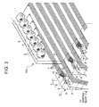
- Figure 2 is an enlarged perspective view showing how groups of warps from package groups are supplied to yarn switching mechanisms.
- Figure 3 is a plan view showing the entire system.
- Figure 4 is a vertical sectional view of showing the configuration and arrangement of the yarn switching mechanism.
- Figure 5 is a side view illustrating a sizing step.
- Figure 6 is a perspective view showing the general configuration of a partial warping system in accordance with an embodiment of the present invention.
- Figure 7 is an enlarged perspective view showing how groups of warps from package groups are supplied to yarn switching mechanisms.
- Figure 8 is a plan view showing the entire system.
- Figure 9 is a vertical sectional view of showing the configuration and arrangement of the yarn switching mechanism.
- Now, embodiments of the present invention will be described. Figure 1 is a perspective view showing the general configuration of a beam warping system in accordance with an embodiment of the present invention. Figure 2 is an enlarged perspective view showing how groups of warps from package groups are supplied to yarn switching mechanisms. Figure 3 is a plan view showing the entire beam warping system. Figure 4 is a vertical sectional view showing the configuration and arrangement of the yarn switching mechanisms.
- Figure 1 is a perspective view showing the entire beam warping system. The
beam warping system 1 comprises afirst warping creel 10a and asecond warping creel 10b on which a large number of supplyingpackages beam warper 2 around which several hundred warps Y unwound from the supplyingpackages 5 are wound while being arranged in parallel to form awarping beam 11. - The
beam warping system 1 also comprises a plurality ofyarn switching boxes first warping creel 10a and the beam warper 2 (warping beam 11); theyarn switching boxes yarn switching mechanisms 3. - Each of the warping
creels packages 5 set on the fixed creel are not movable. In the present embodiment, thefirst warping creel 10a is configured so that 384 supplyingpackages 5 can be set in 48 columns in a lateral direction and in 8 stages in a vertical direction. On the other hand, thesecond warping creel 10b is configured so that 84 supplyingpackages 5 can be set. As shown in Figures 1 and 4, thesecond warping creel 10b is provided away from thefirst warping creel 10a so that the side of thesecond warping creel 10b on which the supplyingpackages 5 are set stands opposite thefirst warping creel 10a. ' - As shown in Figure 1, the supplying
packages 5 are conical packages. On thefirst warping creel 10a, a number of (in the present embodiment, 6) supplyingpackages 5 of different yarn colors or types are combined into onepackage group 4 as shown in Figures 1, 3, and 4 and others. For example, for different yarn colors, a first supplyingpackage 5 has a red yarn, a second supplyingpackage 5 has a yellow yarn, a third supplyingpackage 5 has a blue yarn, and so on. - The number of
package groups 4 that can be set on thefirst warping creel 10a corresponds to a fraction of the number of warps Y constituting onewarping beam 11. Specifically, thebeam warper 2 in the present embodiment winds 148 warps around thewarping beam 11, and the number ofpackage groups 4 that can be set on thefirst warping creel 10a corresponds to a fraction of the number of the warps, that is, 64. The corresponding number of supplyingpackages 5 is 64 × 6 = 384. The 64package groups 4 are provided on a one-to-one correspondence with the same number of, that is, 64yarn switching mechanisms 3 described later. - As shown in Figure 1, each of the
yarn switching boxes 12 is elongate in the vertical direction, and the internal space of theyarn switching box 12 is partitioned into 8 pieces. Each of the resulting partitions P, P, ... accommodates theyarn switching mechanism 3, comprising ayarn selecting device 7 and a knotter (splicing device) 8 as shown in Figure 2. - In other words, the yarn switching mechanism 3 (
yarn selecting device 7 and knotter 8) is placed in each of the 8 partitions P formed in the correspondingyarn switching box 12. That is to say, 8yarn switching mechanisms 3 are arranged in parallel in the vertical direction in each of theyarn switching boxes 12. Although Figure 1 and others omit several of the plurality ofyarn switching boxes 12, the 8yarn switching boxes 12 are arranged at intervals. As a result, 8 × 8 = 64yarn switching mechanisms 3 are installed. In the description below, the 64yarn switching mechanisms 3 are numbered from 1 to 64 (#1 to #64). -
Reference numeral 9 in Figure 2 is a sensor that detects yarn breakage, and onesensor 9 is provided for eachyarn switching mechanism 3. - As shown in Figures 2 to 4, each of the
yarn selecting device 7 in each of theyarn switching mechanisms 3 is supplied with a group of warps Y, Y, ... unwound from thecorresponding package group 4 on thefirst warping creel 10a. Specifically, 6 warps Y, Y, ... are unwound from the respective supplyingpackages 5 having various yarn colors and constituting thecorresponding package group yarn selecting device 7 in the correspondingyarn switching mechanism 3 via an appropriate yarn guide. - As shown in Figures 2 and 3, only one (or more) warp Y, which is approprietly selected by the
yarn selecting device 7, among the group of warps Y, Y, ... supplied to theyarn selecting device 7 in eachyarn switching mechanism 3 is supplied to thewarping beam 11 side. - On the other hand, 84 supplying
packages second warping creel 10b. As shown in Figures 1 and 3 and others, a group of warps Y, Y, ... unwound from the respective supplyingpackages 5 on thesecond warping creel 10b are supplied directly to thewarping beam 11 side without passing through theyarn switching mechanisms 3; instead, 12 warps pass through each of 7 gaps between the 8 upstandingyarn switching boxes - To be easily seen, Figure 1 omits the middle of a yarn path from each supplying packages 5 on the
first warping creel 10a to the correspondingyarn switching box 12. Yarn paths from the suplying packages 5 on thesecond warping creel 10b to the warping beams 11 are also appropriately omitted. - The
yarn selecting device 7 is configured similarly to that disclosed in the Patent Document A and theyarn selecting device 7 will be described below in brief with reference to Figures 3 and 4 and others. Theyarn selecting device 7 comprises 6 yarn guides 17, 17, ... provided in association with the 6 yarns Y, Y, ... supplied, a cylinder (not shown in the drawings) that can individually rotatively move the 6 yarn guides 17, a suction nozzle (suction means; not shown in the drawings) that can suck the warps Y, and a holdingroller 18 that holds the yarn end of each warp Y against the suction force so that the warp Y can stand by. - Each of the yarn guides 17 is cylindrical so that the warp Y supplied can be inserted through the
yarn guide 17. The 6 yarn guides 17 can be independently switched between an elevated position (selected position) and a lowered position (selection canceled position or retracted position) by the cylinder. - The
knotter 8 is provided immediately downstream side of theyarn selecting device 7. Theknotter 8 has a common configuration and theknotter 8 may be, for example, the well-known one disclosed in the Patent Document A and its detailed description is thus omitted. - A description will be given below of how the yarn switching mechanism 3 (
yarn selecting device 7 and knotter 8) configured as described above switches the warps Y. As shown in Figure 2, 6 warps Y, Y, ... introduced into theyarn selecting device 7 in eachyarn switching mechanism 3 are inserted through the respective yarn guides 17, 17, ..., provided in theyarn selecting device 7. Theyarn selecting device 7 selects one or more of the 6 warps Y and controls the cylinder so that the yarn guides 17 corresponding to the selected warps Y are located at the upper selected position, while the yarn guides 17 for the unselected warps Y are located at the lower retracted position. - When the
yarn guide 17 is switched to the selected position, the yarn end of the warp Y guided through thatyarn guide 17 can be delivered to thedownstream side knotter 8. When theyarn guide 17 is at the retracted position, the yarn end of the warp Y is not delivered to theknotter 8 but is held by the holdingroller 18 to stand by. - To switch the currently selected warp Y being supplied to the selected
warping beam 11 side to a warp Y of a different color (or yarn type), theyarn switching mechanism 3 configured as described above drives the cylinder to lower theyarn guide 17 corresponding to the currently supplied warp Y, to the retracted position. Theyarn switching mechanism 3 also elevates theyarn guide 17 through which the newly selected warp Y is being guided, from the retracted position to the selected position. Theknotter 8 then cuts the current warp Y and splices the resulting yarn end (which is closer to thewarping beam 11 side) to the yarn end of the new warp Y. The yarn end (which is closer to the supplyingpackage 5 side) of the unselected warp Y is automatically held by the holdingroller 18 to stand by, thus allowing for selection of this warp Y in the future. This enables the switching of the color (or yarn type) of the warp Y to be supplied to thewarping beam 11. - 64 warps Y, Y, ... selected by the
yarn selecting devices 7 and drawn out of the 64yarn switching mechanisms 3 are fed to areed 13 providing a width as shown in Figure 1. 84 warps Y, Y, ... drawn out from the otherside warping creel 10b and having passed between theyarn switching boxes reed 13 as shown in Figure 1. Subsequently, a total of 148 warps Y, Y, ... having passed through thereed 13 so as to lie parallel to one another are wound over a predetermined length in the direction of a thick arrow in Figure 1. Thewarping beam 11 is thus formed. - The
beam warper 2 comprises an electric motor (motor) 19 that rotatively drives thewarping beam 11, and theelectric motor 19 is, for example, a pulse motor or a servo motor that can perform angular control. Theelectric motor 19 is connected to a controller (warper controller) 20 in thebeam warper 2, which controls rotation and stoppage of theelectric motor 19. Thewarper controller 20 is connected to a higher system controller (control device) 21 in order to control the entirebeam warping system 1. - Once the warps Y, Y, ... are wound over a predetermined length to form a
warping beam 11, thewarping beam 11 is removed from thebeam warper 2, and the above process is then repeated to newly wind the yarns Y, Y, ... to form awarping beam 11. The present embodiment uses thebeam winding system 1 shown in Figure 1 to form two warping beams 11. The next step involves drawing out a large number of warps Y, Y, ... from a plurality of warpingbeams 11 including the above two and aligning and sizing the warps Y (sizing step). - During the sizing step, a plurality of the warping beams 11 are arranged upstream side as shown in Figure 5. Figure 5 shows only 10
warping beams 11 for the simplification of description. In the present embodiment, thebeam warping system 1 in Figure 1 forms only two warpingbeams 11 with asterisks (*). The remaining warping beams 11 are formed by a normal beam warper (without switching the warps Y). All the 148 warps Y in these warpingbeams 11 are white. - In Figure 5, after 148 warps Y, Y, ... are drawn out from each warping
beam 11, these warps Y, Y, ... are combined and aligned together. The warps Y, Y, ... are subsequently appropriately guided by a plurality of guide rolls 24, while being immersed and sized in a sizingvessel 25. The warps Y, Y, ... are then wound around aweaving beam 26. Thus, theweaving beam 26 is formed around which for example, 4,000 to 5,000 warps have been wound. Theweaving beam 26 is then supplied to the subsequent weaving process. - In the
beam warping system 1 in accordance with the present embodiment, as shown in Figure 1, thesystem controller 21 is electrically connected to each of the 64 yarn switching mechanisms 3 (Figure 1 shows only the input of signals to some of the yarn switching mechanisms 3) so as to be able to individually control theyarn switching mechanisms 3. Although not shown in the drawings in detail, thesystem controller 21 in the present embodiment is composed of a well-known microcomputer. Thesystem controller 21 comprises a CPU serving as calculating means, a ROM and a RAM serving as storage means, an output section and so on that outputs control signals to thewarper controller 20 andyarn switching mechanisms 3. - Information on the winding length of the
warping beam 11 is preset in thesystem controller 21 and stored in the storage means such as the RAM. Thesystem controller 21 calculates the rotation angle of thewarping beam 11 corresponding to the stored length, and thesystem controller 21 transmits an instruction to thewarper controller 20 in order to drive thewarping beam 11 by the rotation angle. Upon receiving this instruction, thewarper controller 20 controllably drives theelectric motor 19 for thebeam warper 2 by the specified rotation angle. Thewarping beam 11 is thus rotated through the predetermined rotation angle to enable the 148 warps Y to be simultaneously wound to form awarping beam 11 of the predetermined length. - In accordance with woven patterns, the
system controller 21 inputs and sets information on switching positions for the warps Y and the target warps Y (switching information) for each of the 64 of the (148) warps Y in onewarping beam 11 which pass through theyarn switching mechanisms 3. Thesystem controller 21 can then store the set information in the storage means such as the RAM. - The following is an example of switching information: "At a winding start position, the warps Y Nos. 1 to 32 are all blue. At a position 180 meters away from the winding start position, the warps Y Nos. 6 and 32 are switched to yellow. At a position 230 meters away from the winding start position, the warps Y Nos. 6 and 25 are switched to red". The numbers (1 to 64) of the warps Y correspond to the numbers (Nos. 1 to 64, #1 to #64) of the
yarn switching mechanisms 3. In the description below, all the 84 supplyingpackages creel 10b contain white warps. - In the above description, the
system controller 21 rotates thewarping beam 11 through the rotation angle corresponding to the distance from the winding start position to a switching position on the basis of the switching information. Thesystem controller 21 then selectively activates the yarn switching mechanisms 3 (yarn selecting devices 7 and knotters 8) corresponding to the warps Y to be switched. The warps Y are thus switched. - A description will be given of a specific example of control based on the above example of switching information. The
system controller 21 first sends signals to theyarn switching mechanisms 3 Nos. 1 to 64 so that a blue warp Y is selected and supplied for all the warps Y Nos. 1 to 64. Thesystem controller 21 subsequently drives theelectric motor 19 via thewarper controller 20 to start winding the warps Y around thewarping beam 11. Thewarping beam 11 is continuously driven until the position of theyarn switching mechanisms 3 coincides with the position 180 meters away from the winding start position, and thewarping beam 11 is then stopped. Thesystem controller 21 subsequently sends a yarn switching instruction signal to theyarn switching mechanisms 3 Nos. 6 and 32 to switch the warps Y Nos. 6 and 32 from blue to yellow. - The
yarn switching mechanisms 3 other than Nos. 6 and 32 do not perform a switching operation. In other words, at the position 180 meters away from the winding start position, only Nos. 6 and 32 of the 64yarn switching mechanisms 3 are selectively actuated. However, this corresponds to the set yarn switching information. Where yarn switching information is set indicating that for example, all the warps Nos. 1 to 64 are to be switched to yellow, all theyarn switching mechanisms 3 Nos. 1 to 64 are actuated. - After the switching is completed, the
electric motor 19 is driven again to drive thewarping beam 11 to a rotation angle at which theyarn switching mechanisms 3 are located at the position 230 meters away from the winding start position, and thewarping beam 11 is then stopped. Thesystem controller 21 sends a yarn switching instruction signal to theyarn switching mechanisms 3 Nos. 6 and 25 to selectively actuate them. The warps Y Nos. 6 and 25, for which theseyarn switching mechanisms 3 are responsible, are thus switched to red. - This control enables beam warping to be carried out so that while 148 warps are being wound around one
warping beam 11, the colors or types of 64 of these 148 warps are varied in the longitudinal direction. This enables diverse patterns to be made. For example, theweaving beam 26 formed by combining the above warping beams 11 together can have stripes of blue, white, white, blue, white, blue, white, white, ..., stripes of blue, white, white, yellow, white, blue, white, white, ..., or stripes of blue, white, white, red, white, red, white, white, ... - The present embodiment also eliminates the need for a preparing step of forming special supplying packages the number of which is equal to the large number of warps as in the configuration described in the Patent Document A. This enables the warping process to be greatly simplified.
- The present embodiment also sets the switching positions by controlling the rotation angle of the
warping beam 11. This reduces the misalignment among the switching positions for the warps Y within onewarping beam 11, thus enabling intended patterns to be appropriately expressed. Further, measurements are carried out on the basis of the rotation angle of thewarping beam 11 driven by theelectric motor 19. This eliminates the need for special measuring devices, thus contributing to simplifying the configuration. - As described above, the
beam warping system 1 in accordance with the present embodiment includes the warpingcreels packages 5 for supplying the warps Y can be set, and thebeam warper 2, which simultaneously winds the plurality of warps Y, Y, ... supplied from the warpingcreels warping beam 11. The plurality ofyarn switching mechanisms 3, each comprising theyarn selecting device 7 and theknotter 8, are installed in the yarn path between the warping creel (first warpingcreel 10a) and thebeam warper 2; theknotter 8 splices the warp Y selected by theyarn selecting device 7. Thefirst warping creel 10a is configured so that thepackage group 4, comprising of a plurality of the supplyingpackages 5 of different yarn colors, can be set for each of theyarn switching mechanisms 3. Then, theyarn selecting device 7 in theyarn switching mechanism 3 is supplied with the group of warps Y, Y, ... unwound from thepackage group 4. Theyarn selecting device 7 then selects at least one of the supplied group of warps Y, Y, ... and supplies the selected warp Y to thewarping beam 11 side. - This enables the
yarn switching mechanism 3 to switch the warp Y, thus making it possible to easily and flexibly adjust to a change in pattern or the like. Thebema warping system 1 is thus provided with excellent general-purpose properties. - In the
beam warping system 1 in accordance with the present embodiment, the number (64) ofyarn switching mechanisms 3 is smaller than that (148) of warps Y simultaneously wound around thewarping beam 11. - In other words, some, that is, 64 of the 148 warps Y, Y, ... simultaneously wound around the
warping beam 11 are selected and supplied by theyarn selecting devices 7 in theyarn switching mechanisms 3. The remaining 84 warps are supplied from the supplyingpackages 5 without passing through theyarn switching mechanisms 3. - Consequently, the
yarn switching mechanism 3 need not be installed for each of the warps Y, Y, ... forming thewarping beam 11. Only a required number ofyarn switching mechanisms 3 need be arranged as desired. This makes it possible to simplify the configuration to reduce the required installation space. - The
beam warping system 1 in accordance with the present invention comprises thesystem controller 21, which performs control such that while the warps Y are being wound around thewarping beam 11 over a predetermined length, all or selected ones of a plurality of theyarn switching mechanisms 3 are actuated to switch selection of the warps Y fed to thewarping beam 11 side. - This enables the colors of the warps Y constituting the
warping beam 11 to be switched during the formation of thewarping beam 11. Very diverse patterns can thus be provided. Moreover, while a plurality of warps Y, Y, ... are being simultaneously wound around thewarping beam 11, the colors of the warps Y are switched both individually and concurrently at every warp Y. This suppresses the misalignment among the switching positions for the warps Y, thus enabling excellent patterns to be made. The present embodiment also makes it possible to omit the preparing step of forming such packages as are required for the Patent Document A. The Lead time, man-hour, and costs can thus be remarkably reduced. Moreover, the simultaneous winding and concurrent switching of the warps Y enable a reduction in errors in the switching positions for the warps Y in thewarping beam 11. This suppresses appearing patterns from being disfigured or disarranged. - Owing to the reduced errors in switching positions, the
beam warping system 1 in accordance with the present embodiment enables warping over a length from several meters to several thousand meters. Therefore, beam warping of a very high degree of freedom can be achieved. - The method described in the Patent Document A may significantly misalign the switching positions for the warps, and this misalignment is accumulated as the winding of the warps around the warping drum progresses. Toward a winding end position, the range of the misalignment may exceed one meter. Consequently, where short warps of length about several meters are arranged near the winding end position of the warping drum, when those parts of the warps are excluded which must be disposed of as a result of the misalignment, few available parts remain which can be used for a weaving process. As a result, the method disclosed in the Patent Document A has been forced to adopt a warp layout in which relatively short warps are arranged at the winding start position, whereas relatively long warps are arranged at the winding end position.
- In contrast, the present embodiment can reduce the errors in the switching positions for the warps Y even when the
warping beam 11 approaches the winding end position. Shorter warps Y can thus be arranged near the winding end position of thewarping beam 11. This makes it possible to freely design the longitudinal layout of the warps Y in thewarping beam 11, thus avoiding wasting the warps Y, while increasing the production efficiency of a post-process. - In the present embodiment, the
beam warper 2 comprises theelectric motor 19, which can rotatively drive thewarping beam 11 while angularly controlling it. Thesystem controller 21 rotates thewarping beam 11 through the angle corresponding to a preset switching position, and then to actuate all or selected ones of theyarn switching mechanisms 3 to switch selection of the warps Y. - This configuration sets the switching position for each warp on the basis of the rotation angle of one
warping beam 11. This makes it possible to further reduce the relative misalignment among the switching positions for the warps Y in thewarping beam 11. Intended patterns can thus be appropriately expressed without undergoing disfiguring or the like. Further, the need for special measuring devices is eliminated, thus contributing to simplifying the configuration. - The direct positioning based on the rotation angle of the
warping beam 11 also enables a reduction in the absolute misalignment among the switching positions. For example, in the present embodiment, thebeam warping system 1 winds the warps Y around the two warpingbeams 11 with asterisks (*) shown in Figure 5, while switching the warps Y, on the basis of exactly the same switching information. However, even with the combination of the two warpingbeams 11 shown in Figure 5, the above described reduced errors serve to reduce the misalignment among the switching positions for the warps Y in the two warpingbeams - The present embodiment also carries beam warping as described below. The warps Y are fed from the plurality of supplying
packages warping creels warping beam 11. Thepackage groups 4 each comprising a plurality of supplyingpackages creel 10a. Each of theyarn selecting devices 7 provided on a one-to-one correspondence with thepackage groups 4 is supplied with the group of warps Y, Y, ... unwound from thecorresponding package group 4. Eachyarn selecting device 7 selects and supplies at least one warp Y of the supplied warp group Y, Y, ... to thewarping beam 11. Theknotters 8 are provided on a one-to-one correspondence with theyarn selecting devices 7 to splice the warps Y selected by theyarn selecting devices 7. - This provides a general-purpose beam warping method that can adjust easily and flexibly to a change in pattern or the like.
- With the beam warping method in accordance with the present embodiment, some, that is, 64 of the 176 warps Y simultaneously wound around the
warping beam 11 are selected and supplied by theyarn selecting devices 7 in theyarn switching mechanisms 3. The remaining 84 warps Y are supplied from the supplyingpackages yarn switching mechanisms 3. - This method enables a reduction in the number of
yarn selecting devices 7 and knotters 8 and thus in installation costs, as described above. - Further, with the beam warping method in accordance with the present embodiment, while the warps Y are being wound around the
warping beam 11 over a predetermined length, all or selected ones of a plurality of theyarn switching mechanisms 3 are actuated to switch selection of the warps Y fed to thewarping beam 11 side. - This method enables very diverse patterns to be made by switching the colors of the warps Y constituting the
warping beam 11 during winding of the warps Y around thewarping beam 11. The misalignment among the switching positions for the warps Y can also be reduced, thus enabling intended patterns to be appropriately expressed. - The preferred embodiment of the present invention has been described. However, the above embodiment may be modified as described below.
- The non-drum
type beam warper 2, shown in Figure 1, may be replaced with a drum type beam warper driven by friction of a contact drum. In this case, theelectric motor 19 is connected to the drum to drive thewarping beam 11 while angularly controlling it via the drum. - In the above description, the winding length of warps Y is recognized on the basis of the rotation angle of the
warping beam 11. This may be replaced with a configuration described below. Thebeam warper 2 comprises a measuring roller (rotator) that rotates in contact with the warps Y before they are wound around thewarping beam 11 and a rotation sensor that detects rotation of the measuring roller, and thesystem controller 21 recognizes the winding length of the warps Y on the basis of a signal from the rotation sensor. In this case, the switching positions for the warps Y are set on the basis of the signal from the rotation sensor. This enables the switching positions to be accurately and reliably set to appropriately express the intended positions. - In the present embodiment, the warping
creels first warping creel 10a and thesecond warping creel 10b may be integrated into one warping creel. Each of the warpingcreels creels - In the above description, 64 of the 148 warps Y selected and supplied by the
yarn switching mechanisms 3 are wound at a plurality of positions across the width of thewarping beam 11 as shown in Figure 1. However, the arrangement of the warps Y shown in Figure 1 and others is only illustrative. The warps Y may be wound at any positions across the width of thewarping beam 11. - The present embodiment adopts the
knotter 8 as a splicing device. However, theknotter 8 may be replaced with another splicing device such as a splicer. Tension devices, yarn guides, or the like may be provided at appropriate positions on the warping creel 10 or in the middle of the path of the warps Y. - The above embodiment installs the 64
yarn switching mechanisms 3. However, more or lessyarn switching mechanisms 3 may be installed. It is also possible to provide as manyyarn switching mechanisms 3 as the warps Y wound around thewarping beam 11, that is, 148yarn switching mechanisms 3 so as to enable all of the 148 warps Y to be switched. - In the above embodiment, the
yarn switching mechanism 3 is composed of theyarn selecting device 7 andknotter 8. However, theyarn switching mechanism 3 may further comprise a yarn storing device that can store the warps Y. This makes it possible to reduce or zero the time for which winding is stopped so as to allow the warps Y to be switched during winding of the warps Y around thewarping beam 11. - The number of warps Y selected by each
yarn selecting device 7 is not limited to one. By using 2 of the 6 yarn guides 17, 17 in theyarn selecting device 7 as selected positions, it is possible to simultaneously supply the two warps Y, Y to thewarping beam 11 side. This enables more diverse patterns to be made. - The following numbers are not limited to the above values: the number of warps Y wound around one
warping beam 11 in thebeam warper 2, the number ofyarn switching mechanisms 3, and the number of supplyingpackages package group 4. These numbers may be appropriately varied depending on the specification of thebeam warper 2 or the like. For example, the combination of yarn co.lors or types of the supplyingpackages - Now, a description will be given of application of the present invention to a partial warping system.
- A partial warping method has been known as a warping method for preparing for weaving. The partial warping method draws out and supplies yarns from a plurality of (for example, about several tens of to several hundred) supplying packages set on a warping creel and forms the warps into a band at a tapered end of a warping drum having a tapered winding surface. In other words, the yarns are wound into a single layer obliquely to the axis of the warping drum, the layer having a width smaller than that of the drum in its axial direction.
- Then, a second band is similarly formed adjacent to the first band. The above operation is then repeated until a required total number of yarns are wound around the warping drum. The yarns are then simultaneously drawn out from the partial warping beam around which a total number of warps required for weaving have been wound. The yarns are then used to form one weaving beam (or a plurality of partial warping beams may be formed into one weaving beam). The partial warping is commonly because of its ability to avoid an increase in the size of facilities and its suitability for small-quantity and multikind production.
- The partial warping is executed by a partial warping facility disclosed in the
Japanese Patent No. 3492335 bobbin creel 9, a conveyor 10, a yarn drawing-out portion 14, abobbin installing position 11, and an automatic cutting and joining device 18) (hereinafter referred to as Patent Document B"). The partial warping facility disclosed in the Patent Document B comprises the bobbin creel which serves as a warping creel and which is of a replaceable type using a conveyor in the form of a rotating table. The bobbin installing portion composed of two or more bobbin creels is provided in association with each yarn drawing-out portion. The rotating table can selectively move the bobbin installing portion to an operation position. - The partial warping facility disclosed in the Patent Document B comprises the automatic cutting and joining device that cuts a yarn from its bobbin side or joins it to another bobbin. One automatic cutting and joining device is provided for a plurality of yarn drawing-out portions arranged in a horizontal line (see Figure 4 of the Patent Document B). This unit moves among the plurality of yarn drawing-out portions to cut warps and join the cut warps as required. In other words, the single automatic cutting and joining device is responsible for a plurality of warps and cuts and joints the warps while moving as required.
- Every time a partial beam warper finishes one warp band yarn layer (one band), the configuration disclosed in the Patent Document B can change a yarn sequence (yarn colors or types) forming a next warp band yarn layer. Consequently, at least two warp band yarn layers with warps the number of which is smaller than that of warps required for a repeat (unit of periodic repetition of the color pattern of warps constituting a pattern) can be used to form a larger repeat. This makes it possible to provide compact facilities that do not require any large production floor. Alternatively, productivity can be improved by forming a warp band yarn layer with warps the number of which is larger than that of warps required for a repeat.
- The Patent Document A discloses a warping method which, taking woven patterns into account, continuously winds yarns of various colors or types while measuring the yarns to a predetermined length in a longitudinal direction of the yarns, to form a plurality of supply packages, supplies the supplying packages to predetermined positions on a warping creel, carries out partial warping to wind the yarns around a partial warping beam, and then forms one weaving beam. The warping method disclosed in the Patent Document A uses a yarn measuring and storing device to measure the length of the warps.
- The Patent Document A can provide a partial warping beam that correctly expresses woven patterns, simply by arranging finished supplying packages at predetermined positions on the warping creel.
- The configuration described in the Patent Document B selects the yarn by using the rotating table to move the selected bobbin to the yarn drawing-out portion. This requires the scale of the yarn selecting device to be increased, thus raising facility costs and the like. Further, the single automatic cutting and joining device cuts and joins a plurality of warps while moving. Consequently, switching a large number of warps at a time requires a considerably long time including a standby time. This increases an idle time to lower production efficiency.
- Further, the Patent Document B only discloses the configuration that can change the yarn sequence every time warps have been wound into one band. The Patent Document B does not refer to a change in the colors or types of warps in one band (during the formation of one band).
- On the other hand, the method disclosed in the Patent Document A can change the colors or types of warps in one band in the longitudinal direction of the warps. Thus, this method can advantageously manufacture fabrics with diverse patterns. However, this method requires an additional step of manufacturing supplying packages with the changed yarn colors or types the number of which corresponds to the width of the fabrics; the step precedes the partial warping process. This sharply increases man-hour and costs.
- The method disclosed in the Patent Document B forms each supplying package by switching the yarn colors or types while using a yarn measuring and storing device to measure the length of the yarn. Thus, even if an attempt is made to form each supplying package by switching a plurality of warps at the same switching position, the warps may be switched at different switching positions during actual partial warping owing to an error in measurement or a change in condition such as temperature or humidity during winding. In particular, this misalignment tends to be accumulated as winding of warps into supplying packages progresses. This may result in significant misalignment. This may in turn causes the resulting patterns to be disfigured or disarranged, thus making it difficult to appropriately obtain intended patterns is difficult.
- The problems to be solved by the present invention have been described. Now, a description will be given of means for solving the problems as well as its effects.
- A first aspect of the present invention provides a partial warping system configured as described below. The partial warping system includes a partial warper comprising a warping creel on which a plurality of supplying packages for supplying warps can be set and a warping drum around which a plurality of warps supplied from the warping creel are simultaneously wound to form a band. Yarn switching mechanisms are arranged between the warping creel and the warping drum and each comprise a yarn selecting device and a splicing device that splices a warp selected by the yarn selecting device; the number of yarn switching mechanisms at least corresponds to the number of warps in one band. The warping creel is configured so that package groups each comprising a plurality of the supplying packages having at least either different yarn colors or different yarn types can be set in association with the respective yarn switching mechanisms. A warp group unwound from the package group are supplied to the yarn selecting device in the yarn switching mechanism. The yarn selecting device is configured to select and supply at least one warp of the supplied warp group to the warping drum side.
- Like the Patent Document B, this configuration can use the yarn switching mechanisms to switch the warps after a band has been finished and before the next band starts to be formed. This enables a pattern to be formed without any problems even if the number of warps in the periodic repetition unit required to form the pattern is not equal to the number of warps in one band. Therefore, the partial warping system is compact and has high productivity or enables an increase in the degree of freedom of expression of the pattern.
- Unlike the Patent Document B, the present invention only requires each splicing device to be responsible for splicing of one warp. This enables the yarn colors or the like to be simultaneously switched in a short time even for a large number of warps, thus improving productivity. Further, the one-to-one correspondence between the yarn switching devices and the warps enables the control of the splicing devices to be simplified. Moreover, the warping creel supplies a warp group unwound from a package group to each yarn selecting device, which then selects a warp from the warp group. This eliminates the need for a large scale configuration such as in the Patent Document B, which uses the rotating table to select from bobbins. This in turn reduces the installation costs and the time required to switch yarn selection and saves energy consumed by the yarn selecting devices.
- In the partial warping system, the warping creel is preferably of a fixed type.
- This makes it possible to simplify the configuration of the warping creel to reduce the installation costs.
- The partial warping system preferably comprises a control device that performs control such that while the warps are being wound around the warping drum over a predetermined length, all or selected ones of a plurality of the yarn switching mechanisms are actuated to switch selection of the warps fed to the warping drum side.
- This enables the colors or types of the warps constituting a band to be switched within the winding length of that band. More diverse patterns can thus be made as is the case with the Patent Document A.
- Further, in contrast to the Patent Document A, this configuration enables the colors or types of an appropriate number of warps required for one band to be switched both independently and concurrently, while simultaneously winding a number of warps required for one band. This enables the omission of a cumbersome preparing step of forming as many packages as the warps in one band as in the Patent Document A. Lead time, man-hour, and costs can thus be reduced. Moreover, the simultaneous winding and the concurrent switching enable a reduction in relative errors in switching positions for the warps in one band compared to the method disclosed in the Patent Document A. This suppresses appearing patterns from being disfigured or disarranged.
- The partial warping system is preferably configured as described below. The partial warper comprises a motor that can rotatively drive the warping drum while angularly controlling the warping drum. The control device is configured to rotate the warping drum through an angle corresponding to a preset switching position, and then to actuate all or selected ones of a plurality of the yarn switching mechanisms to switch selection of the warps.
- This configuration sets the switching position for each warp on the basis of the rotation angle of the warping drum, around which an appropriate number of warps required for one band are simultaneously wound. This makes it possible to further reduce the relative misalignment among the switching positions for the warps in one band. Intended patterns can thus be appropriately expressed without undergoing disfiguring or the like. Further, the need for special measuring devices is eliminated, thus contributing to simplifying the configuration.
- A second aspect of the present invention provides a partial warping method described below. The partial warping method supplies warps from a plurality of supplying packages set on a warping creel and simultaneously winds the warps around a warping drum. Package groups each comprising a plurality of supplying packages having at least either different yarn colors or different yarn types are set on the warping creel; the number of the package groups corresponds to the number of warps in one band. Each of yarn selecting devices corresponding to one of the package groups is supplied with a warp group unwound from the package group. Each of the yarn selecting devices is configured to select and supply at least one warp of the supplied warp group to the warping drum. Splicing devices are provided on a one-to-one correspondence with the yarn selecting devices to splice the yarn selected by the yarn selecting devices.
- Like the Patent Document A, this configuration can use the yarn selecting devices and splicing devices to switch the warps after a band has been finished and before the next band starts to be formed. This enables a pattern to be formed without any problems even if the number of warps in the periodic repetition unit required to form the pattern is not equal to the number of warps in one band. The facilities can thus be made compact and productivity can be improved. This configuration can even increase the degree of freedom of expression of the pattern.
- Unlike the Patent Document B, this configuration requires each splicing device to be responsible only for splicing of one warp. This enables simultaneous switching to be achieved in a short time even for a large number of warps, thus improving productivity. Further, the one-to-one correspondence between the yarn switching devices and the warps enables the control of the splicing devices to be simplified. Moreover, the warping creel supplies a warp group unwound from a package group to each yarn selecting device, which then selects a warp from the warp group. This eliminates the need for a large scale configuration such as in the Patent Document A, which uses the rotating table to select from bobbins. This in turn reduces the installation costs and the time required to switch yarn selection and saves energy consumed by the yarn selecting devices.
- With the partial warping method, the warping creel is preferably of a fixed type.
- This makes it possible to simplify the configuration of the warping creel to reduce the installation costs.
- Preferably, with this partial warping method, while the warps are being wound around the warping drum over a predetermined length, the warps supplied to the warping drum are switched by the yarn selecting devices and splicing devices corresponding to all or selected ones of the warps in one band.
- This enables the colors or types of the warps constituting a band to be switched within the winding length of that band. More diverse patterns can thus be made as is the case with the Patent Document A.
- Further, in contrast to the Patent Document A, this configuration enables the colors or types of an appropriate number of warps required for one band to be switched both independently and concurrently, while simultaneously winding a number of warps required for one band. This enables the omission of a cumbersome preparing step of forming as many packages as the warps in one band as in the Patent Document A. Lead time, man-hour, and costs can thus be reduced. Moreover, the simultaneous winding and the concurrent switching enable a reduction in relative errors in switching positions for the warps in one band compared to the method disclosed in the Patent Document A. This suppresses appearing patterns from being disfigured or disarranged.
- The partial warping method is preferably configured as described below. The warping drum is driven by a motor that can rotatively drive the warping drum while angularly controlling the warping drum. The warping drum is rotated through an angle corresponding to a preset switching position, and then all or selected ones of the yarn selecting devices and the splicing devices are actuated to switch selection of the warps.
- This method sets the switching position for each warp by controlling the rotation angle of the motor and thus the rotation of the warping drum, around which an appropriate number of warps required for one band are simultaneously wound. This makes it possible to further reduce the relative misalignment among the switching positions for the warps in one band. Intended patterns can thus be appropriately expressed without undergoing disfiguring or the like. Further, the need for special measuring devices is eliminated, thus contributing to simplifying the configuration.
- Now, an embodiment of the present invention will be described. Figure 6 is a perspective view showing the general configuration of a partial warping system in accordance with an embodiment of the present invention. Figure 7 is an enlarged perspective view showing how warp groups from package groups are supplied to yarn switching mechanisms. Figure 8 is a plan view showing the entire system. Figure 9 is a vertical sectional view showing the configuration and arrangement of the yarn switching mechanisms.
- Figure 6 is a perspective view showing the entire partial warping system. The
partial warping system 101 comprises apartial warper 102 including warpingcreels packages drum 111 around which 64 warps Y unwound from the supplyingpackages 105 are wound so as to lie parallel to one another, thus forming a band B. That is to say, in thepartial warper 102 in accordance with the present embodiment, the number of warps Y for one band is set at 64. - The
partial warping system 101 comprisesyarn switching boxes creels drum 111; theyarn switching boxes yarn switching mechanisms 103. Thepartial warping system 101 comprises a lateral pair of warpingcreels yarn switching boxes - Each of the warping
creels packages 105 set on the fixed creel are not movable. As shown in Figures 8 and 9, in the present embodiment, the warpingcreel 110 is configured so that 192 supplyingpackages 105 can be set in 24 columns in a lateral direction and in 8 stages in a vertical direction (a total of 384 supplying packages can be set on the right and left warpingcreels 110, 110). - As shown in Figure 6, the supplying
packages 105 are conical packages. A number of (in the present embodiment, 6 packages 105) supplyingpackages 105 of different yarn colors or types are combined into onepackage group 104. For example, for different yarn colors, a first supplyingpackage 105 has a red yarn, a second supplyingpackage 105 has a yellow yarn, a third supplyingpackage 105 has a blue yarn, and so on. The number ofpackage groups 104 that can be set on the warpingcreel 110 corresponds to the number of yarns constituting one band B. Specifically, in thepartial warper 102 in accordance with the present embodiment, the number of yarns in the band B is 64 as previously described. Thus, 64 package groups 104 (64 × 6 = 384 supplying packages 105) can be set on the warpingcreel 110. The 64package groups 104 are provided on a one-to-one correspondence with the same number of, that is, 64yarn switching mechanisms 103 described later. - The internal space of each
yarn switching box 112 is partitioned into 32 piece arranged in 4 columns in the lateral direction and 8 stages in the vertical direction. Each of the resulting partitions P, P, ... accommodates theyarn switching mechanism 103, comprising ayarn selecting device 107 and a knotter (splicing device) 108 as shown in Figure 7. - In other words, a total of 64 partitions P are formed in the right and left
yarn switching boxes yarn selecting device 107 and knotter 108) placed in each of the partitions P. That is to say, the partial warping system has as manyyarn switching mechanisms 103 as warps Y in one band in thepartial warper 102, that is, 64yarn switching mechanisms 103. In the description below, the 64yarn switching mechanisms 103 are identified by thenumbers 1 to 64 (#1 to #64). -
Reference numeral 109 in Figure 7 is a sensor that detects yarn breakage. Onesensor 109 is provided for eachyarn switching mechanism 3. - As shown in Figures 7 to 9, the
yarn selecting device 107 in each of theyarn switching mechanisms 103 is supplied with a warp group Y, Y, ... unwound from thecorresponding package group 104. That is, 6 warps Y, Y, ... are unwound from the respective supplyingpackages 105 having various yarn colors and constituting thecorresponding package group 104. The warp group Y, Y, ... of the various colors are then supplied to theyarn selecting device 107 in the correspondingyarn switching mechanism 103 via an appropriate yarn guide. To be easily seen, Figure 6 omits the middle of a yarn path from each supplying packages 105 on the warpingcreel 110 to the correspondingyarn switching box 112. - As shown in Figures 7 and 8, only one (or more) warp Y, which is appropriately selected by the
yarn selecting device 107, among the warp group Y, Y, ... supplied to theyarn selecting device 107 in eachyarn switching mechanism 103 is supplied to the warpingdrum 111 side. - The
yarn selecting device 107 is configured similarly to that disclosed in the Patent Document A, and theyarn selecting device 107 will be described in brief with reference to Figures 8 and 9 and others. Theyarn selecting device 107 comprises 6 yarn guides 117, 117, ... provided in association with the 6 warps Y, Y, ... supplied, a cylinder (not shown in the drawings) that can individually rotatively move the 6 yarn guides 117, a suction nozzle (suction means; not shown in the drawings) that can suck the warps Y, and a holdingroller 118 that can hold the yarn end of each warp Y against the suction force so that the warp Y can stand by. - Each of the yarn guides 117 is cylindrical so that the warp Y supplied can be inserted through the
yarn guide 117. The 6 yarn guides 117 can be independently switched between an elevated position (selected position) and a lowered position (selection canceled position or retracted position) by the cylinder. - The
knotter 108 is provided immediately downstream side of theyarn selecting device 107. Theknotter 108 has a common configuration. Theknotter 108 may be, for example, the well-known one disclosed in the Patent Document A and its detailed description is thus omitted. - A description will be given below of how the yarn switching mechanism 103 (
yarn selecting device 107 and knotter 108) configured as described above switches the warps Y. As shown in Figure 7, 6 warps Y, Y, ... introduced into theyarn selecting device 107 in eachyarn switching mechanism 103 are inserted through the respective yarn guides 117, 117, ..., provided in theyarn selecting device 107. Theyarn selecting device 107 selects one or more of the 6 warps Y and controls the cylinder so that the yarn guides 117 corresponding to the selected warps Y are located at the upper selected position, while the yarn guides 117 for the unselected warps Y are located at the lower retracted position. - When the
yarn guide 117 is switched to the selected position, the yarn end of the warp Y guided through thatyarn guide 117 can be delivered to thedownstream side knotter 108. When theyarn guide 117 is at the retracted position, the yarn end of the warp Y is not delivered to theknotter 108 but is held by the holdingroller 118 to stand by. - To switch the currently selected warp Y being supplied to the warping
drum 111 to a warp Y of a different color (or yarn type), theyarn switching mechanism 103 configured as described above drives the cylinder to lower theyarn guide 117 corresponding to the currently supplied warp Y, to the retracted position. Theyarn switching mechanism 103 also elevates theyarn guide 117 through which the newly selected warp Y is being guided, from the retracted position to the selected position. Theknotter 108 then cuts the current warp Y and splices the resulting yarn end (which is closer to thewarping beam 111 side) to the yarn end of the new warp Y. The yarn end (which is closer to the supplyingpackage 105 side) of the unselected warp Y is automatically held by the holdingroller 118 to stand by, thus allowing for selection of this warp Y in the future. This enables the switching of the color (or yarn type) of the warp Y to be supplied to the warpingdrum 111 side. - 64 warps Y, Y, ... selected by the
yarn selecting devices 107 and drawn out of the 64yarn switching mechanisms 103 are fed to and pass through areed 113 so as to lie parallel to one another as shown in Figure 6. Subsequently, the warps Y, Y, ... are wound around the warpingdrum 111 over a predetermined length, the warpingdrum 111 rotating in the direction of a thick arrow in Figure 6. A band B of a predetermined width is thus formed. - The
beam warper 102 comprises an electric motor (motor) 119 that rotatively drives the warpingdrum 111, and theelectric motor 119 is, for example, a pulse motor or a servo motor that can perform angular control. Theelectric motor 119 is connected to a controller (warper controller) 120 in thepartial warper 102, which controls rotation and stoppage of theelectric motor 119. Thewarper controller 120 is connected to a higher system controller (control device) 121 in order to control the entirepartial warping system 101. - Once a band B of a predetermined length is formed by rotatively driving the warping
drum 111 by means of theelectric motor 119, the warpingdrum 111 is moved in the axial direction by an actuator (not shown in the drawings). The warpingdrum 111 is driven by theelectric motor 119 again to wind 64 warps Y around itself to form a next band B. Repeating this operation several to several tens of times results in a partial warping beam comprising warps corresponding to the width of the fabrics. A rewinder then rewinds the warps from the partial warping beam to form a weaving beam, which is supplied to a weaving process. Warps wound around a plurality of partial warping beams may be combined together into one weaving beam. - In the
partial warping system 101 in the present embodiment, as shown in Figure 6, thesystem controller 121 is electrically connected to each of the 64 yarn switching mechanisms 103 (Figure 6 shows only the input of signals to theyarn switching mechanisms 103 #1 to #8) so as to be able to individually control theyarn switching mechanisms 103. Although not shown in the drawings in detail, thesystem controller 121 in the present embodiment is composed of a well-known microcomputer. Thesystem controller 121 comprises a CPU serving as calculating means, a ROM and a RAM serving as storage means, and an output section that outputs control signals to thewarper controller 120 andyarn switching mechanisms 103. - Information on the winding length of the band B is preset in the
system controller 121 and stored in the storage means such as the RAM. Thesystem controller 121 calculates the rotation angle of the warpingdrum 111 corresponding to the stored length, and thesystem controller 121 transmits an instruction to thewarper controller 120 in order to drive the warpingdrum 111 by the rotation angle. Upon receiving this instruction, thewarper controller 120 controllably drives theelectric motor 119 for thepartial warper 102 by the specified rotation angle. The warpingdrum 111 is thus rotated through the predetermined rotation angle to enable the 64 warps Y to be simultaneously wound to form a band B of the predetermined length. - In accordance with woven patterns, the
system controller 121 inputs and sets information on switching positions for the warps Y and the target warps Y (switching information) for each of the warps Y in one or more bands B. Thesystem controller 121 can then store the set information in the storage means such as the RAM. - The following is an example of switching information: "At a winding start position, the warps Y Nos. 1 to 64 are all blue. At a position 180 meters away from the winding start position, the warps Y Nos. 6 and 32 are switched to yellow. At a position 230 meters away from the winding start position, the warps Y Nos. 6 and 35 are switched to red". The numbers (1 to 64) of the warps Y are counted from one widthwise end of a group of warps Y, Y, ... lying parallel to one another after having passed through the
reed 113. In the present embodiment, the numbers of the warps Y, Y, ... correspond to the numbers (Nos. 1 to 64, #1 to #64) of theyarn switching mechanisms 103. - The
system controller 121 rotates the warpingdrum 111 through the rotation angle corresponding to the distance from the winding start position to a switching position on the basis of the switching information. Thesystem controller 121 then selectively activates the yarn switching mechanisms 103 (yarn selecting devices 107 and knotters 108) corresponding to the warps Y to be switched. The warps Y are thus switched. - A description will be given of a specific example of control based on the above example of switching information. The
system controller 121 first sends signals to theyarn switching mechanisms 103 Nos. 1 to 64 so that a blue warp Y is selected and supplied for all the warps Y Nos. 1 to 64. Thesystem controller 121 subsequently drives theelectric motor 119 via thewarper controller 120 to start winding the warps Y around the warpingdrum 111. The warpingdrum 111 is continuously driven until the position of theyarn switching mechanisms 103 coincides with the position 180 meters away from the winding start position, and then the warpingdrum 111 is stopped. Thesystem controller 121 subsequently sends a yarn switching instruction signal to theyarn switching mechanisms 103 Nos. 6 and 32 to switch the warps Y Nos. 6 and 32 from blue to yellow. - The
yarn switching mechanisms 103 other than Nos. 6 and 32 do not perform a switching operation. In other words, at the position 180 meters away from the winding start position, only Nos. 6 and 32 of the 64yarn switching mechanisms 3 are selectively actuated. However, this corresponds to the set yarn switching information. Where yarn switching information is set indicating that for example, all the warps Nos. 1 to 64 are to be switched to red, all theyarn switching mechanisms 103 Nos. 1 to 64 are actuated. - After the switching is completed, the
electric motor 119 is driven again to drive the warpingdrum 111 to a rotation angle at which theyarn switching mechanisms 103 are located at the position 230 meters away from the winding start position, and then the warpingdrum 111 is stopped. Thesystem controller 121 subsequently sends a yarn switching instruction signal to theyarn switching mechanisms 103 Nos. 6 and 35 to selectively actuate them. The warps Y Nos. 6 and 35, for which theseyarn switching mechanisms 103 are responsible, are thus switched to red. - This control enables partial warping to be carried out so that while the warps Y are being wound into one band B, the color or type of each of the warps Y constituting the band B is varied in the longitudinal direction. This enables diverse patterns to be made. It is also possible to eliminate the need for a preparing step of forming special supplying packages the number of which corresponds to the width of the fabrics as in the configuration described in the Patent Document A. This enables the partial warping process to be greatly simplified.
- Further, the switching positions are set by controlling the rotation angle of the warping
drum 111. This reduces the misalignment among the switching positions for the warps Y within one band B, thus enabling intended patterns to be appropriately expressed. Further, measurements are carried out on the basis of the rotation angle of theelectric motor 119 driving the warpingdrum 111. This eliminates the need for special measuring devices, thus contributing to simplifying the configuration. - However, the present embodiment may perform control such that the
yarn switching mechanisms 103 are not actuated during the formation of one band B and such that after one band B is finished, all or some of theyarn switching mechanisms 103 are concurrently actuated to switch the warps Y. This produces effects similar to those of the Patent Document B. Specifically, every time thepartial warper 102 finishes one band B, theyarn switching mechanisms 103 switch the yarn sequence (yarn colors or types) forming a next band B. This prevents the unit of periodic repetition of the color pattern of warps constituting a pattern from being affected by the number of warps in one band. Consequently, freer patterns can be expressed or productivity can be improved. - The number of
knotters 108 provided in the present embodiment corresponds to the number of warps in one band. Each of theknotters 108 thus has only to be responsible for one of the warps Y constituting the band B. A large number of warps Y can be concurrently switched in a short time by allowing the same number ofknotters 108 to share the operation. Since theknotters 108 switch the respective warps Y on a one-to-one correspondence, the control by thesystem controller 121 side can also be simplified. Further, compared to the configuration disclosed in the Patent Document B, which is based on the replaceable creel scheme and which selects yarns by using a rotating table to rotate bobbins, the present embodiment enables the configurations of the warpingcreel 110 andyarn selecting device 107 to be simplified to make these devices compact. The present embodiment also makes it possible to save energy (power) consumed by the yarn selection in theyarn selecting device 107. - As indicated above, the
partial warping system 101 of the present embodiment includes thepartial warper 102 comprising the warpingcreels packages 105 for supplying the warps Y can be set and the warpingdrum 111 around which a plurality of warps Y supplied from the warpingcreels 110 are simultaneously wound to form a band B. Theyarn switching mechanisms 103 are arranged between the warpingcreels 110 and the warpingdrum 111 and each comprise theyarn selecting device 107 and thesplicing device 108 that splices a warp Y selected by theyarn selecting device 107; the number ofyarn switching mechanisms 103 corresponds to the number of warps Y in one band (64), that is, the number ofyarn switching mechanisms 103 is 64. The warpingcreel 110 is configured so that thepackage groups 104 each comprising a plurality of the supplyingpackages yarn switching mechanisms 103. A warp group Y, Y, ... unwound from thepackage group 104 are supplied to theyarn selecting device 107 in theyarn switching mechanism 103, and theyarn selecting device 107 is configured to select and supply at least one warp Y of the supplied warp group Y, Y, ... to the warpingdrum 111 side. - Thus, as is the case with the Patent Document B, every time the
partial warper 102 finishes one band B, theyarn switching mechanisms 103 can change a yarn sequence forming a next band. Consequently, at least two bands with warps the number of which is smaller than that of warps required for a repeat (unit of periodic repetition of the color pattern of warps constituting a pattern) can be used to form a larger repeat. This makes it possible to provide compact facilities that do not require any large production floor. Alternatively, productivity can be improved by forming a warp band yarn layer with warps the number of which is larger than that of warps required for a repeat. - In contrast to the Patent Document B, the present embodiment uses the warping
creel 100 of a fixed type, and the present embodiment further draws out a warp group Y, Y, ... from thepackage group 104 composed of the plurality of supplyingpackages yarn selecting device 107 in theyarn switching mechanism 103. This eliminates the need for a large scale configuration such as in the Patent Document B (which uses the rotating table to move bobbins in order to switch yarns), thus reducing the installation costs and power consumption. Furthermore, the number ofknotters 108 corresponds to the number (64) of warps Y in one band B. Each of theknotters 108 thus has only to be responsible for splicing of one of the warps Y. This enables a large number of yarn sequences to be changed in a short time. Further, control for yarn switching can be simplified. - The
partial warping system 101 comprises thesystem controller 121, which serves as a control device and which performs control such that while a band B is being formed on the warping drum III (the warps Y are being wound around the warpingdrum 111 over a predetermined length), all or selected ones of the 64yarn switching mechanisms 103 are actuated to switch selection of the warps Y fed to the warpingdrum 111 side. - This configuration thus enables a band B to be formed while both independently and concurrently varying the color or type of each of the warps Y constituting the band B in the longitudinal direction. This enables diverse patterns to be made. The configuration also makes it possible to eliminate the need for a preparing step of forming a large number of supplying packages by continuously winding warps of various yarn colors or types while measuring the warps to a predetermined length in the longitudinal direction as shown in the Patent Document A. The partial warping process can thus be significantly simplified. Moreover, while a plurality of warps Y, Y, ... are being concurrently wound around the warping
drum 111, the colors or types of the warps Y are individually switched. This suppresses the misalignment among the switching positions for the warps Y, resulting in proper patterns. - The
partial warper 102 comprises theelectric motor 119 that can rotatively drive the warpingdrum 111 while angularly controlling the warpingdrum 111. Thesystem controller 121 in thepartial warping system 101 is configured to be able to rotate the warpingdrum 111 through an angle corresponding to a preset switching position, and then to actuate all or selected ones of the 64yarn switching mechanisms 103 to switch selection of the warps Y. - Therefore, the switching position for each warp Y is set on the basis of the rotation angle of the warping
drum 111, around which the 64 warps Y for one band B are simultaneously wound. This enables the switching positions to be more directly set. In other words, the present embodiment further reduces the relative misalignment among the switching position for the warps Y in one band B. This enables intended patterns to be more accurately expressed during weaving. Furthermore, theelectric motor 119 for the warpingdrum 111 provides a measuring function to eliminate the need for special measuring devices. This makes it possible to contribute to simplifying the configuration. - The present embodiment carries out partial warping as described below. A band B is formed by supplying warps Y, Y, ... from the plurality of supplying
packages creel 110 and simultaneously winding the warps Y, Y, ... around the warpingdrum 111. Thepackage groups 104 each comprising a plurality of the supplyingpackages creel 110; the number (64) of the package groups corresponding to the number (64) of warps in one band. Each of theyarn selecting devices 107 corresponding to one of thepackage groups 104 is supplied with a warp group Y, Y, ... unwound from thepackage group 104, and each of theyarn selecting devices 107 is configured to select and supply at least one warp Y of the supplied warp group Y, Y, ... to the warpingdrum 111 side. Theknotters 108 are provided on a one-to-one correspondence with theyarn selecting devices 107 to splice the yarn selected by theyarn selecting devices 107. - Thus, as described above, every time the
partial warper 102 finishes one band B, theyarn switching mechanisms 103 can switch a yarn sequence forming a next band B. Similar effects can be produced using facilities simpler than those in the Patent Document B. The time required for yarn switching can also be reduced. In particular, in the present embodiment, the warpingcreel 110 is of a fixed type and thus has a simplified configuration. - With this partial warping method, while the warps Y are being wound around the warping
drum 111 over a predetermined length, the warps supplied to the warpingdrum 111 can be switched by theyarn selecting devices 107 and knotters 108 (that is, the yarn switching mechanisms 103) corresponding to all or selected ones of the warps Y, Y, ... constituting one band. - As described above, this configuration enables a band B to be formed while both independently and concurrently varying the color or type of each of the warps Y constituting the band B in the longitudinal direction. This enables diverse patterns to be made. Accurate patterns with minimized misalignment can be obtained during weaving.
- The warping
drum 111 is driven by theelectric motor 119 that can rotatively drive the warpingdrum 111 while angularly controlling the warpingdrum 111. The warpingdrum 111 is rotated through an angle corresponding to a preset switching position, and then all or selected ones of theyarn selecting devices 107 andknotters 108 are actuated to switch selection of the warps Y. - Consequently, the switching position for each warp Y is set by adjusting the rotation angle of the
electric motor 119 to control rotation of the warpingdrum 111, around which an appropriate number of warps Y, Y, ... required for one band B can be simultaneously wound. This makes it possible to reduce the relative misalignment among the switching position for the warps Y in one band B. Intended patterns can thus be appropriately expressed without undergoing disfiguring or the like. The present embodiment also eliminates the need for special measuring devices such as the one described in the Patent Document A. This contributes to simplifying the configuration. - The preferred embodiment of the present invention has been described but may be modified, for example, as described below.
- (1) The above embodiment adopts the
knotter 108 as the splicing device. However, in place of theknotter 108, an alternative splicing device such as a splicer may be adopted. Further, in the present embodiment, the warpingcreel 110 is of a parallel type. However, an alternative arrangement scheme may be adopted. Moreover, a tension device may be provided at an appropriate position on the warpingcreel 110 or in the middle of the yarn path of the warps Y. - (2) The above embodiment installs the 64
yarn switching mechanisms 103 in the system; the number of theyarn switching mechanisms 103 is the same as that of warps in one band. However, the number has only to be at least 64. Of course, for example, spareyarn switching mechanisms 103 may be added to the system in order to allow for failures; the resulting number ofyarn switching mechanisms 103 may exceed the number of warps in one band. - (3) In the above embodiment, the
yarn switching mechanism 103 is composed of theyarn selecting device 107 and theknotter 108. However, a yarn storing device capable of storing the warps Y may further be provided in theyarn switching mechanism 103. This makes it possible to reduce or zero the time for which rotation of the warpingdrum 111 is stopped so as to allow the warps Y to be switched during the formation of a band B. Productivity can therefore be improved. - (4) The number of warps Y selected by each
yarn selecting device 107 is not limited to one. Specifically, provided that two of the six yarn guides 117 in theyarn selecting device 107 are set at selected positions, two warps Y, Y can be simultaneously supplied to the warpingdrum 111. This allows more diverse patterns to be made. - (5) In the
partial warper 102, the number of warps in one band B and the number of supplyingpackages package group 104 are not limited to the above values. These numbers may be appropriately varied depending on the specifications of thepartial warper 102 or the like. The combination of colors or types of the supplyingpackages
Claims (17)
- A beam warping system including a warping creel on which a plurality of supplying packages for supplying warps can be set and a beam warper that simultaneously winds a plurality of warps around a warping beam, the beam warping system being characterized by having a plurality of yarn switching mechanisms arranged in a yarn path formed between the warping creel and the beam warper, each of the yarn switching mechanisms comprising a yarn selecting device and a splicing device that splices a warp selected by the yarn selecting device, the warping creel being configured so that package groups each comprising a plurality of the supplying packages having at least either different yarn colors or different yarn types can be set in association with the respective yarn switching mechanisms, a warp group unwound from the package group being supplied to the yarn selecting device in the yarn switching mechanism, the yarn selecting device being configured to select and supply at least one warp of the supplied warp group to the warping beam side.
- A beam warping system according to Claim 1, characterized in that the number of the yarn switching mechanisms is smaller than the number of warps simultaneously wound around the warping beam.
- A beam warping system according to Claim 1, characterized in that some of the warps simultaneously wound around the warping beam are selected and supplied by the yarn selecting device in the yarn switching mechanism, and the remaining warps are supplied from the supplying packages without passing through the yarn switching mechanisms.
- A beam warping system according to any one of Claims 1 to 3, characterized by further comprising a control device that performs control such that while the warps are being wound around the warping beam over a predetermined length, all or selected ones of a plurality of the yarn switching mechanisms are actuated to switch selection of the warps fed to the warping beam side.
- A beam warping system according to Claim 4, characterized in that the beam warper comprises a motor that can rotatively drive the warping beam while angularly controlling the warping beam, and in that the control device is configured to rotate the warping beam through an angle corresponding to a preset switching position, and then to actuate all or selected ones of a plurality of the yarn switching mechanisms to switch selection of the warps.
- A beam warping system according to Claim 4, characterized in that the beam warper comprises a rotor that rotates in contact with the warps before the warps are wound around the warping beam and a rotation sensor that detects rotation of the rotor, and the control device is configured to recognize the winding length of the warps on the basis of a signal from the rotation sensor, and once the winding length reaches the preset switching position, to actuate all or selected ones of a plurality of the yarn switching mechanisms to switch selection of the warps.
- A beam warping method of supplying warps from a plurality of supplying packages set on a warping creel and simultaneously winding the warps around a warping beam, the beam warping method being characterized in that package groups each comprising a plurality of supplying packages having at least either different yarn colors or different yarn types are set on the warping creel, in that each of yarn selecting devices corresponding to one of the package groups is supplied with a warp group unwound from the package group, in that each of the yarn selecting devices is configured to select and supply at least one warp of the supplied warp group to the warping beam, and in that splicing devices are provided on a one-to-one correspondence with the yarn selecting devices to splice the yarn selected by the yarn selecting devices.
- A beam warping method according to Claim 7, characterized in that some of the warps simultaneously wound around the warping beam are selected and supplied by the yarn selecting device in the yarn switching mechanism, and the remaining warps are supplied from the supplying packages without passing through the yarn switching mechanisms.
- A beam warping method according to any of Claim 7 or Claim 8, characterized in that while the warps are being wound around the warping beam over a predetermined length, all or selected ones of a plurality of the yarn switching mechanisms are actuated to switch selection of the warps fed to the warping beam side.
- A partial warping system including a partial warper comprising a warping creel on which a plurality of supplying packages for supplying warps can be set and a warping drum around which a plurality of warps supplied from the warping creel are simultaneously wound to form a band, the partial warping system being characterized by having yarn switching mechanisms which are arranged between the warping creel and the warping drum and each of which comprises a yarn selecting device and a splicing device that splices a warp selected by the yarn selecting device, the number of yarn switching mechanisms at least corresponding to the number of warps in one band, the warping creel being configured so that package groups each comprising a plurality of the supplying packages having at least either different yarn colors or different yarn types can be set in association with the respective yarn switching mechanisms, a warp group unwound from the package group being supplied to the yarn selecting device in the yarn switching mechanism, the yarn selecting device being configured to select and supply at least one warp of the supplied warp group to the warping drum side.
- A partial warping system according to Claim 10, characterized in that the warping creel is of a fixed type.
- A partial warping system according to Claim 10 or Claim 11, characterized by further comprising a control device that performs control such that while the warps are being wound around the warping drum over a predetermined length, all or selected ones of a plurality of the yarn switching mechanisms are actuated to switch selection of the warps fed to the warping drum side.
- A partial warping system according to Claim 12, characterized in that the partial warper comprises a motor that can rotatively drive the warping drum while angularly controlling the warping drum, and in that the control device is configured to rotate the warping drum through an angle corresponding to a preset switching position, and then to actuate all or selected ones of a plurality of the yarn switching mechanisms to switch selection of the warps.
- A partial warping method of supplying warps from a plurality of supplying packages set on a warping creel and simultaneously winding the warps around a warping drum, the partial warping method being characterized in that package groups each comprising a plurality of supplying packages having at least either different yarn colors or different yarn types are set on the warping creel, the number of the package groups corresponding to the number of warps in one band, in that each of yarn selecting devices corresponding to one of the package groups is supplied with a warp group unwound from the package group, in that each of the yarn selecting devices is configured to select and supply at least one warp of the supplied warp group to the warping drum, and in that splicing devices are provided on a one-to-one correspondence with the yarn selecting devices to splice the yarn selected by the yarn selecting devices.
- A partial warping method according to Claim 14, characterized in that the warping creel is of a fixed type.
- A partial warping method according to Claim 14 or Claim 15, characterized in that while the warps are being wound around the warping drum over a predetermined length, the warps supplied to the warping drum are switched by the yarn selecting devices and splicing devices corresponding to all or selected ones of the warps for one band.
- A partial warping method according to Claim 16, characterized in that the warping drum is driven by a motor that can rotatively drive the warping drum while angularly controlling the warping drum, and in that the warping drum is rotated through an angle corresponding to a preset switching position, and then all or selected ones of the yarn selecting devices and the splicing devices are actuated to switch selection of the warps.
Applications Claiming Priority (2)
| Application Number | Priority Date | Filing Date | Title |
|---|---|---|---|
| JP2005195719A JP4445437B2 (en) | 2005-07-05 | 2005-07-05 | Partial warping system and partial warping method |
| JP2005258680A JP2007070759A (en) | 2005-09-07 | 2005-09-07 | Warping system and warping method |
Publications (2)
| Publication Number | Publication Date |
|---|---|
| EP1741814A2 true EP1741814A2 (en) | 2007-01-10 |
| EP1741814A3 EP1741814A3 (en) | 2009-01-21 |
Family
ID=37075958
Family Applications (1)
| Application Number | Title | Priority Date | Filing Date |
|---|---|---|---|
| EP06009269A Withdrawn EP1741814A3 (en) | 2005-07-05 | 2006-05-04 | Warping system and warping method |
Country Status (1)
| Country | Link |
|---|---|
| EP (1) | EP1741814A3 (en) |
Cited By (7)
| Publication number | Priority date | Publication date | Assignee | Title |
|---|---|---|---|---|
| US9487887B1 (en) | 2013-03-13 | 2016-11-08 | Jonathan Grossman | Systems and methods for manufacturing textiles |
| EP3121316A1 (en) * | 2015-07-20 | 2017-01-25 | Stäubli Sargans AG | Yarn arranging machine |
| CN107675309A (en) * | 2017-11-24 | 2018-02-09 | 江苏海特服饰股份有限公司 | A kind of fancy yarn splicer |
| CN111876881A (en) * | 2020-08-03 | 2020-11-03 | 岳西县长宁织绸有限责任公司 | Silk material roller feedway |
| CN112334609A (en) * | 2018-06-20 | 2021-02-05 | 范德威尔公司 | Yarn storage device for yarn processing machines |
| CN113684580A (en) * | 2021-09-30 | 2021-11-23 | 浙江轩泰新材料有限公司 | Production line for fiber thread weaving |
| CN114381838A (en) * | 2020-10-20 | 2022-04-22 | 卡尔迈耶斯托尔研发有限公司 | Method for warping warp threads and sectional warping machine |
Family Cites Families (3)
| Publication number | Priority date | Publication date | Assignee | Title |
|---|---|---|---|---|
| DE10029492C2 (en) * | 2000-06-15 | 2003-04-24 | Mayer Textilmaschf | Warping plant and warping process |
| EP1524341A1 (en) * | 2003-10-13 | 2005-04-20 | Benninger AG | Process and device for changing threads, particularly for the creel or a warping machine |
| JP4086775B2 (en) * | 2003-12-25 | 2008-05-14 | 有限会社スズキワーパー | Partial warping machine and partial warping method |
-
2006
- 2006-05-04 EP EP06009269A patent/EP1741814A3/en not_active Withdrawn
Cited By (11)
| Publication number | Priority date | Publication date | Assignee | Title |
|---|---|---|---|---|
| US9487887B1 (en) | 2013-03-13 | 2016-11-08 | Jonathan Grossman | Systems and methods for manufacturing textiles |
| EP3121316A1 (en) * | 2015-07-20 | 2017-01-25 | Stäubli Sargans AG | Yarn arranging machine |
| CN106367861B (en) * | 2015-07-20 | 2020-12-01 | 史陶比尔萨尔甘斯股份公司 | Yarn finishing machine |
| TWI747830B (en) * | 2015-07-20 | 2021-12-01 | 瑞士商史托比利薩甘斯股份有限公司 | Yarn arranging machine, sizing machine and method for preparing a warp with a desired yarn arrangment |
| CN107675309A (en) * | 2017-11-24 | 2018-02-09 | 江苏海特服饰股份有限公司 | A kind of fancy yarn splicer |
| CN112334609A (en) * | 2018-06-20 | 2021-02-05 | 范德威尔公司 | Yarn storage device for yarn processing machines |
| CN111876881A (en) * | 2020-08-03 | 2020-11-03 | 岳西县长宁织绸有限责任公司 | Silk material roller feedway |
| CN111876881B (en) * | 2020-08-03 | 2021-09-14 | 岳西县长宁织绸有限责任公司 | Silk material roller feedway |
| CN114381838A (en) * | 2020-10-20 | 2022-04-22 | 卡尔迈耶斯托尔研发有限公司 | Method for warping warp threads and sectional warping machine |
| CN114381838B (en) * | 2020-10-20 | 2023-10-20 | 卡尔迈耶斯托尔研发有限公司 | Method for warping warp and sectional warping machine |
| CN113684580A (en) * | 2021-09-30 | 2021-11-23 | 浙江轩泰新材料有限公司 | Production line for fiber thread weaving |
Also Published As
| Publication number | Publication date |
|---|---|
| EP1741814A3 (en) | 2009-01-21 |
Similar Documents
| Publication | Publication Date | Title |
|---|---|---|
| KR101696319B1 (en) | Optical cable Winding System | |
| US6173480B1 (en) | Electronically controlled sample warper with fixed and rotary creels | |
| EP2671830B1 (en) | Textile machine, standby position determining method of driven member of winding unit, and winding unit | |
| JP7034249B2 (en) | Winder | |
| JP4445437B2 (en) | Partial warping system and partial warping method | |
| ITMI951657A1 (en) | SERVICE DEVICE FOR A TEXTILE MACHINE PRODUCING CROSSED REELS | |
| US6385826B1 (en) | Sample warper with detector for yarn on yarn guide | |
| JP5161204B2 (en) | Knitting yarn switching method and knitting yarn switching device | |
| EP1510605A2 (en) | Warping machine having knot aligning device | |
| JP5255572B2 (en) | Device and partial warping method for positioning a yarn within the width of a warp band | |
| TWI453313B (en) | Pattern warping machine | |
| JP3944727B2 (en) | Yarn splicing device for different types of yarn | |
| CN100513282C (en) | Device for winding up several bunches of threads | |
| JP4706974B2 (en) | Filament winding equipment | |
| JP3930027B2 (en) | Sample warping machine, sample warping method and rotary creel | |
| JP2007070759A (en) | Warping system and warping method | |
| CN106367861B (en) | Yarn finishing machine | |
| CN1958422B (en) | Method for rewinding dye bobbins to cross-wound bobbins | |
| JP2004156185A (en) | Method for warping in sectional warping machine | |
| JP2004156187A (en) | Method for warping warp yarn | |
| JP4086844B2 (en) | Sample warping machine and sample warping method | |
| EP4624401A1 (en) | Yarn winding apparatus | |
| TWI457481B (en) | Pattern warping machine | |
| US4975719A (en) | Multi-stylus recording head manufacturing method and apparatus | |
| CN115053307B (en) | Device and method for winding annular core without using material storage box |
Legal Events
| Date | Code | Title | Description |
|---|---|---|---|
| PUAI | Public reference made under article 153(3) epc to a published international application that has entered the european phase |
Free format text: ORIGINAL CODE: 0009012 |
|
| AK | Designated contracting states |
Kind code of ref document: A2 Designated state(s): AT BE BG CH CY CZ DE DK EE ES FI FR GB GR HU IE IS IT LI LT LU LV MC NL PL PT RO SE SI SK TR |
|
| AX | Request for extension of the european patent |
Extension state: AL BA HR MK YU |
|
| PUAL | Search report despatched |
Free format text: ORIGINAL CODE: 0009013 |
|
| AK | Designated contracting states |
Kind code of ref document: A3 Designated state(s): AT BE BG CH CY CZ DE DK EE ES FI FR GB GR HU IE IS IT LI LT LU LV MC NL PL PT RO SE SI SK TR |
|
| AX | Request for extension of the european patent |
Extension state: AL BA HR MK YU |
|
| STAA | Information on the status of an ep patent application or granted ep patent |
Free format text: STATUS: THE APPLICATION HAS BEEN WITHDRAWN |
|
| 18W | Application withdrawn |
Effective date: 20090408 |